

Meyer Industrial, 8865, 8720 Parts Manual
/2018
DO NOT OPERATE EQUIPMENT UNTIL THIS MANUAL HAS BEEN READ AND UNDERSTOOD
OPERATOR
2004 MODEL YEAR
S AND PARTS MANUAL NO. PB
TWIN EXPELLER SUPER SPREADER
MANUFACTURED BY
Meyer Mfg. Corp.
Phone
INDUSTRIAL SERIES
MODEL 8720
MODEL 8865
PATENTED
U.S. PATENT NUMBER
5,368,236
5,501,404
674 W. Business Cty Rd A
P.O. Box 405
Dorchester, Wisconsin 54425
5132 • Fax
800
sales@meyermfg.com
www.meyermfg.com
THROUGH 2017 MODEL YEAR
715
8720/8865
’
-SI-
: 715-654-
1-
-325-9103
E-mail:
Website:
8
:
-654-5513
.

1. INTRODUCTION
Congratulations on your purchase of a new Meyer
farm equipment product. Undoubtedly you have
given much consideration to your purchase and
we’re proud that you have selected Meyer. Pride in
craftsmanship, engineering and customer service
has made Meyer products the finest in the farm
equipment industry today.
There is no substitute for quality. That is why
thousands of people like you have purchased
Meyer farm equipment. They felt it was the best
equipment to serve their farming needs, now and in
years to come. We ask that you follow our policy of
“safety first,” and we strongly suggest that you read
through the owner’s manual before operating your
Meyer farm equipment.
Meyer Manufacturing Corporation wants to thank
you for not compromising quality. We are
determined to offer excellence in customer service
as well as provide you with the very best value for
your dollar.
REMEMBER:
FARM EQUIPMENT BUYERS
TRUST THE NAME MEYER!
Sincerely,
All Employees of
MEYER MANUFACTURING CORPORATION
This SAFETY ALERT SYMBOL means
ATTENTION! BE CAREFUL! YOUR SAFETY IS
INVOLVED! It stresses an attitude of HEADS UP
FOR SAFETY. When you see this symbol, be alert
to the possibility of PERSONAL INJURY and
carefully read the message that follows.
WARNING: NEVER OPERATE WITHOUT
ALL COVERS, SHIELDS AND GUARDS IN
PLACE. KEEP HANDS, FEET AND CLOTHING
AWAY FROM MOVING PARTS. SOME COVERS
AND GUARDS HAVE BEEN REMOVED FOR
ILLUSTRATIVE PURPOSES ONLY IN THIS
MANUAL. FAILURE TO HEED MAY RESULT IN
SERIOUS PERSONAL INJURY OR DEATH.
Meyer Mfg. Corp. reserves the right to make
improvements in design, or changes in
specifications at any time, without incurring any
obligation to owners of units previously sold.
This supersedes all previous published instructions.
IMPORTANT:
At the front of this manual is an “Owner’s
Registration Form”. Be sure your dealer has
completed this form and promptly forwarded a copy
to Meyer Mfg. to validate the manufacturer’s
warranty. The product model and serial number are
recorded on this form and below for proper
identification of your Meyer Industrial Spreader by
your dealer and the manufacturer when ordering
repair parts.
Model No.
Serial No.
Date of Purchase
At the back of this manual is the repair parts section.
All replacement parts are to be obtained from or
ordered through your Meyer dealership. When
ordering repair parts, refer to the parts section and
give complete information including quantity, correct
part number, detailed description and even Model
No. and Serial No. of the Meyer Industrial Spreader
which needs repair parts.
1.1. HOW TO READ YOUR
SERIAL NUMBER
The serial number plate is found on the upper left
front corner of the spreader tank or stamped in the
left front frame channel.
Example: SI128720253
Model Type / Model Year / Model / Sequence of Build
SI 12 8720 253
You are urged to study this manual and follow the
instructions carefully. Your efforts will be repaid in
better operation and service as well as a savings in
time and repair expenses. Failure to read this
manual and understand the machine could lead to
serious injury. If you do not understand instructions
in this manual, contact either your dealer or Meyer
Manufacturing Corp. at Dorchester, WI 54425.
NOTE: All references to right hand (RH), left hand
(LH), front and rear apply to the product as viewed
from the rear of the spreader.
Model 8720 / 8865 - 2 -

Spreader
Check List
PRE-DELIVERY & DELIVERY CHECK LIST
Meyer Manufacturing Corporation
Phone: 715-654-5132 • Toll-Free: 1-800-325-9103 • P.O. Box 405 • Dorchester, WI 54425
This Pre-Delivery & Delivery Check List must be gone through by the Selling Party and the Customer to validate the
Owner’s Registration Form.
PRE-DELIVERY CHECK LIST
After the New Meyer Spreader has been completely
set up, check to be certain it is in correct running order
before delivering it to the customer.
The following is a list of points to inspect:
Check off each item as you have made the proper
adjustments and found the item operating
satisfactorily. Any adjustments made, must be
according to specifications defined in this manual.
All shields and guards are in place and securely
fastened.
All bolts and other fasteners are secure and tight.
All mechanisms operate trouble free.
All grease fittings have been lubricated, gear
boxes filled to proper levels, and all roller chains
are oiled. See “Lubrication” section of this
manual.
PTO shields turn freely.
All roller chain springs adjusted properly for
automatic tensioning. See “Adjustments” section
in this manual.
Both LR and RR Spinner Material Guides are
adjusted properly. See “Adjustments” section in
this manual.
All decals are in place and legible.
All stop/tail/turn lights work properly.
DELIVERY CHECK LIST
The following check list is an important reminder of
valuable information that MUST be passed on to the
customer at the time the unit is delivered.
Check off each item as you explain it to the
customer.
Explain to the customer that pre-delivery check
list was fully completed.
Give customer the Owner & Operator’s Manual.
Instruct to read and completely understand its
contents BEFORE attempting to operate the
spreader.
Explain and review with customer the New Meyer
Spreader manufacturer’s warranty.
Show the customer where to find the serial
number on the implement.
Explain and review with the customer “Safety
Precautions” section of this manual.
Explain and review with customer the proper
“Start-up and Operating Procedures” sections of
this manual.
Demonstrate the PTO Shaft Locking Device and
proper PTO shaft storage. Also, demonstrate
proper hydraulic hose storage and tip holder
used to keep system clean from contaminants.
Explain that regular lubrication and proper
adjustments are required for continued proper
operation and long life of the spreader. Review
with the customer the “Lubrication” and
“Adjustments” sections of this manual.
Explain and review with customer the
recommended loading and unloading procedures
for different types of manure.
Also, demonstrate the proper way to adjust the
Rear Spinner Material Guides.
Fully complete this “PRE-DELIVERY &
DELIVERY CHECK LIST” with the customer.
Model 8720 / 8865 - 3 -

Model 8720
8865
Meyer Manufacturing Corporation
674 W. Business Cty Rd A
Dorchester, WI 54425
Phone: 1
Fax: 715
sales@meyermfg.com
Website: www.meyermfg.com
9103
5513
-800-325-
-654-
Email:
/
-4-

TABLE OF CONTENTS
1. INTRODUCTION ................................................................................................................................................... 2
1.1. How to Read Your Serial Number .................................................................................................................. 2
PRE-DELIVERY CHECK LIST ................................................................................................................................... 3
DELIVERY CHECK LIST ............................................................................................................................................ 3
TABLE OF CONTENTS ............................................................................................................................................ 5
2. MANUFACTURER’S WARRANTY ........................................................................................................................ 7
3. SAFETY PRECAUTIONS ...................................................................................................................................... 8
4. SAFETY FIRST ...................................................................................................................................................... 9
5. PRE-OPERATION ............................................................................................................................................... 11
5.1. Shutting Off and Locking Out Power ............................................................................................................ 11
5.2. Tractor Setup ................................................................................................................................................ 11
5.3. Product Inspection........................................................................................................................................ 12
5.3.1. Wheels and Tires ................................................................................................................................... 12
5.3.2. Axle, O-Beams, Spindles AND Hitch ..................................................................................................... 12
5.3.3. CRACKS ................................................................................................................................................ 12
5.3.4. WORN COMPONENTS ........................................................................................................................ 12
5.3.5. HYDRAULICS ....................................................................................................................................... 12
5.4. Hitching to Tractor ........................................................................................................................................ 12
5.5. PTO Driveline ............................................................................................................................................... 13
5.5.1. Understanding the PTO Cut-Out Clutch ................................................................................................ 13
5.5.2. PTO, Attachment of .............................................................................................................................. 14
5.6. Operational Checks ...................................................................................................................................... 14
5.7. Transporting ................................................................................................................................................. 14
5.7.1. Speed .................................................................................................................................................... 14
5.7.2. Public Roadway Travel .......................................................................................................................... 14
5.7.2.1. Truck Mounted Spreader Lights .................................................................................................... 15
5.7.3. Minimum Tractor Weight ....................................................................................................................... 15
5.7.4. Safety Chain .......................................................................................................................................... 15
5.7.5. Optional Brake Package ........................................................................................................................ 15
6. OPERATION ........................................................................................................................................................ 16
6.1. Loading ......................................................................................................................................................... 16
6.1.1. Overloading ........................................................................................................................................... 16
6.2. Unloading ..................................................................................................................................................... 17
6.2.1. Shear Sprocket ...................................................................................................................................... 18
6.2.2. Freezing Weather Operation ................................................................................................................. 18
7. ADJUSTMENTS .................................................................................................................................................. 19
7.1. Front Drive Roller Chains ............................................................................................................................. 19
7.2. Spinner Material Guides ............................................................................................................................... 21
7.3. Shear Arm Material Guide ............................................................................................................................ 21
8. LUBRICATION ..................................................................................................................................................... 22
8.1. Daily Lubrication (every 8-12 loads) ............................................................................................................. 22
8.2. Weekly Lubrication (every 25-30 loads) ....................................................................................................... 22
8.3. Monthly Lubrication ...................................................................................................................................... 23
8.4. PTO Lubrication ........................................................................................................................................... 23
8.4.1. Lubrication ............................................................................................................................................. 23
8.4.1.1. Prior To Use .................................................................................................................................. 24
8.4.1.2. Normal Operation .......................................................................................................................... 24
8.5. Automatic Chain Oiler .................................................................................................................................. 24
8.6. Truck Mount Mechanical Drive, Lubrication of (Optional) ............................................................................ 25
8.6.1. Monthly Lubrication ............................................................................................................................... 25
8.6.2. Daily Lubrication .................................................................................................................................... 25
9. STORAGE AFTER USE ...................................................................................................................................... 26
10. REPLACEMENT PARTS ................................................................................................................................... 27
10.1. Introduction ................................................................................................................................................. 27
10.2. Cracks ........................................................................................................................................................ 28
Model 8720 / 8865 -5-

10.3. Worn Components ..................................................................................................................................... 28
10.4. Hydraulics ................................................................................................................................................... 28
1000 RPM PTO Drive Shaft-Lemon Profile (Standard 8720) (Optional 8865) ................................................ 30
1000 RPM PTO Drive Shaft-Star Profile (Standard 8720) (Optional 8865) .................................................... 32
1000 RPM PTO Drive Shaft-Lemon Profile (Optional 8720) (Standard 8865) ................................................ 36
1000 RPM PTO Drive Shaft-Star Profile (Optional 8720) (Standard 8865) .................................................... 36
First Reduction & Spinner Drive ...................................................................................................................... 40
Second Reduction Drive .................................................................................................................................. 44
Third Reduction Drive ...................................................................................................................................... 46
Final Reduction, RH Auger Drive .................................................................................................................... 48
Final Reduction, LH Auger & Third Auger Drive .............................................................................................. 50
Body, Shields & Augers - 8720 Spreader ........................................................................................................ 52
Body, Shields & Augers - 8865 Spreader ........................................................................................................ 56
Rear Gate & Shields ........................................................................................................................................ 62
Rear Gate & Shields ........................................................................................................................................ 64
Spinners & Gearboxes .................................................................................................................................... 66
Spinner Gear Reducer - Left Hand (1:1) #19-0129 ......................................................................................... 70
Spinner Gear Reducer - Center (1:1) #19-0130 .............................................................................................. 71
Corner Gear Reducer - Right Hand ................................................................................................................. 72
Axle & Wheels (Standard 8720) ...................................................................................................................... 73
Axle & Wheels, Hi-Float Package (Standard 8865) (Optional 8720) .............................................................. 74
Highway Lights ................................................................................................................................................ 76
Gearbox Attachment Assembly, Truck ............................................................................................................ 78
19-0140 Lower Gearbox - Truck ...................................................................................................................... 79
619-0010-SYN Upper Gearbox - Truck ........................................................................................................... 80
Oil-Kit ............................................................................................................................................................... 82
Truck Mount Fenders ...................................................................................................................................... 84
TROUBLESHOOTING ............................................................................................................................................. 85
WHEEL TORQUE .................................................................................................................................................... 86
8720/8865 Spreader W/Brakes Tire Wheel Torque ............................................................................................ 86
TIRE INFLATION ..................................................................................................................................................... 86
DIMENSIONS & SPECIFICATIONS ........................................................................................................................ 87
MAINTENANCE RECORD ...................................................................................................................................... 91
Model 8720 / 8865 -6-

2. MANUFACTURER’S WARRANTY
MEYER INDUSTRIAL SPREADER
I. The “Owner’s Registration Form” must be completed in full and promptly returned to Meyer Mfg. Corp. for this
warranty to become both valid and effective. All warranties on new Meyer Industrial Spreaders shall apply only to
the original retail customer from an authorized Meyer Mfg. Corp. dealership.
II. This warranty shall not apply to any Meyer Industrial Spreader which has been subjected to misuse, negligence,
alteration, accident, incorrect operating procedures, has been used for an application not designed for or preauthorized by Meyer in writing, has had the serial numbers altered, or which shall have been repaired with parts
other than those obtained through Meyer Mfg. Corp. Meyer is not responsible for the following: Depreciation or
damage caused by normal wear, lack of reasonable and proper maintenance, failure to follow the operator’s
manual recommendations or normal maintenance parts and service. Meyer is not responsible for rental of
replacement equipment during warranty repairs, damage to a power unit (including but not limited to a truck or
tractor), loss of earnings due to equipment down time, or damage to equipment while in transit to or from the
factory or dealer.
III. Meyer Mfg. Corp. warrants new Meyer Industrial Spreaders to be free from defects in material and workmanship
under recommended use and maintenance service, as stated in the “Owner / Operator’s Manual & Parts Book”
as follows:
IV. COMMERCIAL USE: Coverage as in paragraph III.A.1. ONLY, except warranty coverage is for (90) days for
V. Repairs eligible for labor warranty must be made by Meyer Mfg. Corp. or an authorized Meyer dealership. The
VI. Except as stated above, Meyer Mfg. Corp. shall not be liable for injuries or damages of any kind or nature, direct,
VII. No person is authorized to give any other warranties or to assume any other obligation on Meyer Mfg. Corp.’s.
Purchased Product Warranty:
This warranty does not apply to component parts not manufactured by Meyer such as but not limited to wheels, tires,
tubes, PTO shafts, clutches, hydraulic cylinders, scales, etc.
A. Meyer Mfg. Corp. will repair or replace F.O.B. Dorchester, WI, as Meyer Mfg. Corp. elects, any part of a
new Meyer Industrial Spreader which is defective in material or workmanship:
i. Without charge for either parts or labor during the first (1) year from purchase date to the
original retail customer.
B. In addition to the above basic warranty, Meyer Mfg. Corp. will repair or replace F.O. B. Dorchester, WI
as Meyer Mfg. Corp. elects:
i. Any part of the following which is defective in material or workmanship (not neglect to
recommended use and service) with a “pro-rated” charge for parts only (not labor) during the
stated time period from date of purchase to the original retail customer:
Seven (7) Years: a. The spreader tank body is warranted against rust through (Pro-rated parts only).
Parts included, front and rear end panels, side panels and auger trough.
parts and labor to the original commercial retail customer.
original retail customer is responsible for any service call and/or transportation of the Industrial Spreader to the
dealership or factory for warranty service.
consequential, or contingent, to persons or property. This warranty does not extend to loss of crop or for any
other reasons.
behalf unless made or assumed in writing by Meyer Mfg. Corp. This warranty is the sole and exclusive warranty
which is applicable in connection with the manufacture and sale of this product and Meyer Mfg. Corp.’s
responsibility is limited accordingly.
Model 8720 / 8865 -7-
11/2014

3. SAFETY PRECAUTIONS
CAUTION: BEFORE ATTEMPTING TO OPERATE THIS SPREADER, READ AND STUDY THE
FOLLOWING SAFETY INFORMATION. IN ADDITION, MAKE SURE THAT EVERY INDIVIDUAL WHO
OPERATES OR WORKS WITH THE SPREADER, WHETHER FAMILY MEMBER OR EMPLOYEE, IS FAMILIAR
WITH THESE SAFETY PRECAUTIONS.
Require anyone who will operate this spreader to read and completely understand this Owner’s Manual. Give
necessary instructions!
DO NOT operate, service, inspect or otherwise handle this spreader until all operators have read this Owner’s
Manual and have been properly trained in the intended usage of the spreader.
Do not allow minors (children) or inexperienced persons to operate this spreader.
If the spreader becomes clogged, shut off the tractor engine and allow all mechanisms to stop. Disconnect PTO
shaft and hydraulic hoses (relieve hydraulic pressure). Then, clean or work on the spreader as required.
Always shut off power and disconnect PTO drive shaft and unhook hydraulic hoses (relieve hydraulic pressure)
from tractor to prevent accidental startup or unexpected movement before working on machine.
Do not clean, adjust, or lubricate while spreader is in motion.
Make sure all hydraulic fittings are tight and that all hoses are in good condition. Hydraulic fluid escaping under
pressure can have sufficient force to penetrate skin and cause serious injury. Never investigate for hydraulic leaks
by using a part of the body to feel for escaping fluid.
Inspect when first delivered and regularly thereafter. Verify that all connections and bolts are tight and secure
before operating.
Know how to stop the spreader before starting it!
Do not operate until all shields, covers and guards are in place.
Make certain everyone is clear of the spreader before applying power.
Keep hands, feet and clothing away from moving parts. Loose or floppy clothing should not be worn by the
operator.
Stay well clear of the spreader’s rear discharge spinners while operating.
Do not step up on any part of the spreader at any time. Do not use PTO guard as a step.
Do not step over the power take-off shaft. Stay clear of the PTO at all times.
Keep PTO shaft telescoping tube shields turning freely. Keep PTO master shield on tractor. Replace shields
missing or damaged.
Match the right tractor PTO spline and speed with the PTO driveshaft provided with the implement. This will assure
proper geometry and operating speed. Never operate 540 RPM implements at 1000 RPM. Never operate 1000
RPM implements at 540 RPM. Never use a spline adapter. Use of adaptors will void warranty due to damage
caused to the tractor PTO, PTO driveshaft or implement.
Use only properly rated tires.
Do not tow at speeds in excess of 20 MPH when transporting this spreader. Never exceed a safe travel speed.
Observe all applicable traffic laws when transporting on public roadways (where legal to do so). Check local laws
for all highway lighting and marking requirements.
Always install a SMV emblem on this spreader for transporting on roadways and keep the emblem clean and bright.
When towing the spreader on public roads a safety chain of sufficient strength to support, along the line of
travel, the gross weight of the spreader must be used (See Maximum Load Weight Chart in the Transporting
Section). The safety chain should be attached per diagram in the Transporting Section.
STUDY THE ABOVE SAFETY RULES
FAILURE TO HEED MAY RESULT IN SERIOUS PERSONAL INJURY OR DEATH.
Model 8720 / 8865 -8-
4. SAFETY FIRST
A brief definition of signal words that may be used in this manual is as follows:
This symbol is used to call attention to instructions concerning personal safety. Be sure to observe
and follow these instructions. Take time to be careful!
DANGER indicates an imminently hazardous situation which, if not avoided, WILL result in serious injury or
death.
WARNING indicates a potentially hazardous situation which, if not avoided, COULD result in death or
serious injury, and includes hazards that are exposed when guards are removed.
CAUTION indicates a potentially hazardous situation which, if not avoided, MAY result in minor or moderate
injury. It is also used to alert against unsafe practices.
CAUTION: READ ALL SAFETY SIGNS ON THE SPREADER AND IN THIS MANUAL. KEEP THESE
SAFETY SIGNS CLEAN AND REPLACE ANY LOST OR DESTROYED SAFETY SIGNS. BECOME FAMILIAR
WITH ALL TRACTOR AND SPREADER CONTROLS.
Model 8720 / 8865 -9-

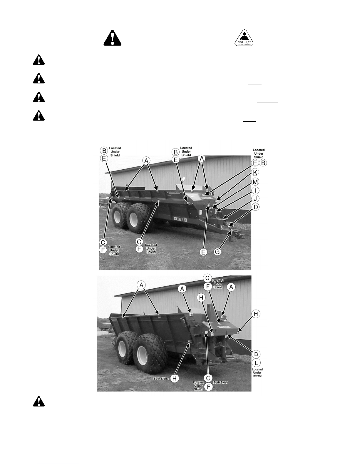
The Meyer Super Spreader is manufactured with operator safety in mind. Located on the manure spreader are
various safety signs to aid in operation and warn of danger or caution areas. Pay close attention to all safety signs
on the spreader.
DO NOT REMOVE ANY SAFETY SIGNS. IF SAFETY SIGNS ARE LOST, DAMAGED OR IF THE
MANURE SPREADER HAS BEEN REPAINTED, REPLACE SAFETY SIGNS. REMEMBER: SAFETY SIGNS
ARE FOR EVERYONE'S PROTECTION AND INFORMATION.
SAFETY SIGN A. PART NO. 46-0001-5 SAFETY SIGN B. PART NO. 46-0001-26 SAFETY SIGN C. PART NO. 46-3600-9
SAFETY SIGN D. PART NO. 46-3600-6 SAFETY SIGN E. PART NO. 46-0001-4
SAFETY SIGN F. PART NO. 46-3600-2 SAFETY SIGN H. PART NO. 46-9500-4
SAFETY SIGN G. PART NO. 46-0001-13
SAFETY SIGN K. PART NO. 46-0001-35
SAFETY SIGN J. PART NO. 46-0004-2
SAFETY SIGN L. PART NO. 46-5570-3 SAFETY SIGN M. PART NO. 46-8500-7
SAFETY SIGN I. PART NO. 46-0001-22
CAUTION: READ ALL SAFETY SIGNS ON THE SPREADER AND IN THIS MANUAL. KEEP THESE
SAFETY SIGNS CLEAN AND REPLACE ANY LOST OR DESTROYED SAFETY SIGNS. BECOME FAMILIAR
WITH ALL TRACTOR AND SPREADER CONTROLS.
IMPORTANT: MEYER MFG. CORP. PROVIDES GUARDS FOR EXPOSED MOVING PARTS FOR THE
OPERATOR’S PROTECTION; HOWEVER, SOME AREAS CANNOT BE GUARDED OR SHIELDED IN ORDER
TO ASSURE PROPER OPERATION. THE OPERATOR’S MANUAL AND SAFETY SIGNS ON THE MACHINE
ITSELF WARN YOU OF DANGERS AND MUST BE READ AND OBSERVED CLOSELY.
Model 8720 / 8865 -10-
5. PRE-OPERATION
WARNING:
PARTICULAR ATTENTION TO THE “SAFETY PRECAUTION” AND “SAFETY FIRST” PAGES. READ ALL
SAFETY MESSAGES HIGHLIGHTED BY “SAFETY ALERT SYMBOLS” THROUGHOUT THE MANUAL.
WARNING
FAILURE TO HEED MAY RESULT IN SERIOUS PERSONAL INJURY OR DEATH.
5.1. SHUTTING OFF AND LOCKING OUT POWER
WARNING
OR SERVICING THIS SPREADER. FAILURE TO HEED MAY RESULT IN SERIOUS PERSONAL INJURY
OR DEATH.
Whenever adjusting, cleaning, lubricating or otherwise servicing this spreader, you must shutoff and lockout
power to the spreader. Because this spreader can be truck mounted or powered by a tractor, methods vary.
On truck mounted units, the connection between the truck and the spreader is permanently installed and not
intended to be disconnected. On trucks, disengage the PTO drive, turn off the engine, set the parking brake,
remove the ignition keys and keep them in your possession to prevent anyone else from accidentally applying
power to the box unexpectedly. For tractors, disconnect the PTO, disconnect and relieve pressure of the
hydraulics, turn off the tractor and set the brakes.
Throughout this manual, when directed to shutoff and lockout power, be familiar with the previously described
procedures for the type of machine you are operating.
BEFORE OPERATING, READ THIS OWNER’S MANUAL COMPLETELY. PAY
: DO NOT OPERATE WITHOUT ALL SHIELDS, GUARDS AND COVERS INSTALLED.
: SHUTOFF AND LOCKOUT POWER BEFORE CLEANING, ADJUSTING, LUBRICATING
5.2. TRACTOR SETUP
IMPORTANT: NEVER OPERATE PTO ABOVE ITS NORMAL 1000 RPM RATING. TRACTOR'S PTO MUST
MATCH IMPLEMENT PTO.
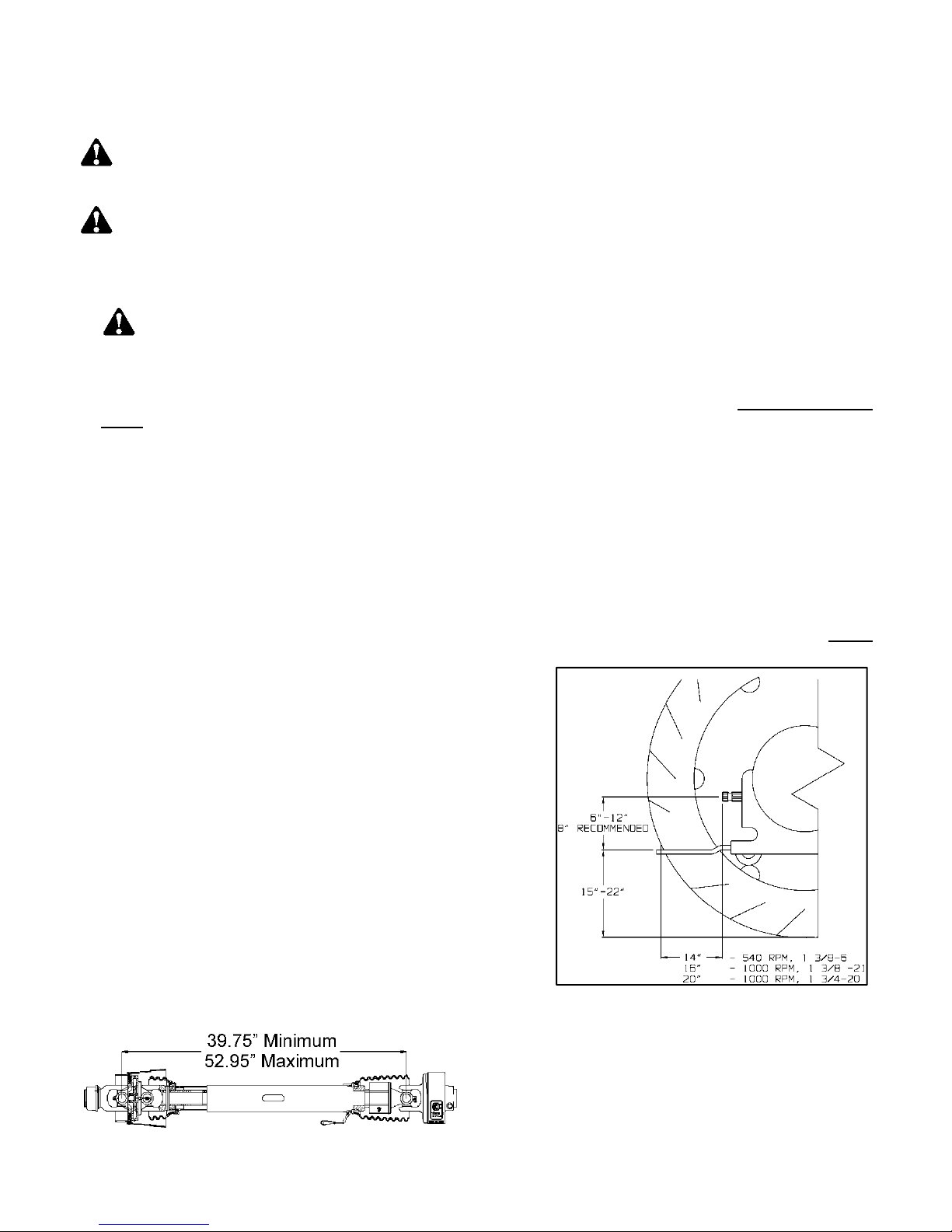
This spreader must be operated with a 1000 RPM PTO. No
PTO adapter may be used to alter speed or geometry. The
hitch of the spreader is designed for a standard tractor
drawbar. Adjust the drawbar at 15 to 22 inches above the
ground. Extend or shorten the drawbar so horizontal distance
from end of tractor PTO shaft to center of the hitch pin hole is
20” (1 3/4-20), 16” (1 3/8-21). Secure the drawbar so that the
hitch pin hole is located directly below the PTO drive line. See
FIGURE 1 for location of standard measurements.
An improperly located hitch point may cause damage to the
universal joints of the PTO drive shaft. Conforming to the
standard 16" or 20” drawbar & PTO relationship will ensure
that the PTO drive shaft will not become over-extended.
WITH INITIAL HOOK-UP TO YOUR NEW MEYER
SPREADER TEST PTO TRAVEL BY TURNING EQUIPMENT
IN BOTH DIRECTIONS OBSERVING THE MINIMUM AND
MAXIMUM TRAVEL DIMENSIONS AS SHOWN, FIGURE 2.
FIGURE 1. TRACTOR DRAWBAR & PTO
SPECIFICATION
Model 8720 / 8865 -11-
FIGURE 2. PTO DRIVELINE

5.3. PRODUCT INSPECTION
WARNING
SECURE BEFORE OPERATING. FAILURE TO HEED MAY RESULT IN SERIOUS PERSONAL INJURY OR
DEATH.
5.3.1. WHEELS AND TIRES
See page 86 for Wheel Torque and Tire Inflation Charts.
Check for proper assembly and adjustment and make sure that all bolts are tightened. Securely retighten
after a few hours of operation, as bolts can loosen up on new machinery. Check wheel lug nuts upon delivery
and periodically thereafter. Check the tires and inflate to the recommended pressure. See wheel torque and
tire inflation charts on page 86.
5.3.2. AXLE, O-BEAMS, SPINDLES AND HITCH
DANGER
SHIELDING, SAFETY SIGNS AND SAFETY LIGHTING REGULARLY. THESE PARTS OF YOUR
IMPLEMENT, IF NOT WATCHED CLOSELY, COULD POSE POTENTIAL INJURY INCLUDING DEATH.
IF AN ITEM IS FOUND IN NEED OF REPAIR, TAG THIS UNIT AS INOPERABLE AND HAVE QUALIFIED
PERSONNEL REPAIR IMMEDIATELY.
The entire axle, o-beam, spindle and hitch should be visually inspected for cracks regularly. Any cracks
found will indicate immediate repair or replacement is necessary.
Some parts will wear due to use. It is highly recommended to replace critical safety items such as a hitch
that has worn through the "Wear Plate" or is less than three quarters of its original thickness.
: INSPECT REGULARLY THAT ALL CONNECTIONS AND BOLTS ARE TIGHT AND
: INSPECT THE AXLES, O-BEAMS, SPINDLES, TIRES, HITCHES, SAFETY
5.3.3. CRACKS
The entire axle, o-beam, spindle and hitch should be visually inspected for cracks regularly. Any cracks
found will indicate immediate repair or replacement is necessary.
5.3.4. WORN COMPONENTS
Some parts will wear due to use. It is highly recommended to replace critical safety items such as a hitch
that has worn through the "Wear Plate" or is less than three quarters of its original thickness.
5.3.5. HYDRAULICS
WARNING
FORCE TO CAUSE INJURY. KEEP ALL HOSES AND CONNECTIONS IN GOOD SERVICEABLE
CONDITION. FAILURE TO HEED MAY RESULT IN SERIOUS PERSONAL INJURY OR DEATH.
Whenever working on any part of the hydraulics, safely relieve hydraulic pressure before starting.
: HYDRAULIC FLUID ESCAPING UNDER PRESSURE CAN HAVE SUFFICIENT
5.4. HITCHING TO TRACTOR
Do not allow anyone to stand between the tongue or hitch and the tractor when backing up to the spreader.
Fasten the spreader hitch to the tractor drawbar with a hitch pin that cannot bounce out. Use a 1-5/16” to 1-3/8”
diameter hitch pin.
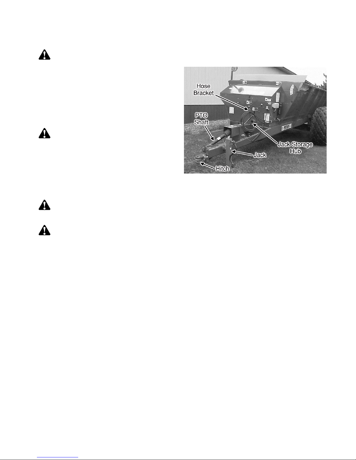
Remove the weight from the jack (jack is not to be used when spreader is loaded). Remove the jack from
mount tube and move to the transport storage tube on the front of the spreader drive enclosure. Store in a
horizontal position.
Before operation and after hitching the tractor to the spreader, connect the PTO drive shaft to the tractor. Slide
the spring loaded locking collar onto the PTO yoke rearward, and then slide the yoke onto the tractor PTO shaft.
Model 8720 / 8865 -12-
Release the spring loaded collar. Be sure the pins fall into the groove of the tractor PTO shaft and that the collar
snaps forward into the locked position.
NOTICE
Route hydraulic hoses through the hose support
rod which is mounted to the hitch frame, Figure 3.
Connect the hydraulic hoses for the flow control
rear gate to the tractor’s double acting valve
hydraulic system. Move the tractor hydraulic
controls to observe proper flow gate operation. If
the controls operate the gate in opposite
directions to what you expect, reverse the
hydraulic hose connections at the tractor.
WARNING
ESCAPING UNDER PRESSURE CAN HAVE
SUFFICIENT FORCE TO CAUSE INJURY.
KEEP ALL HOSES AND CONNECTIONS IN
GOOD SERVICEABLE CONDITION. FAILURE
TO HEED MAY RESULT IN SERIOUS
PERSONAL INJURY OR DEATH.
: DO NOT USE A STEEL HAMMER TO AID IN JOINING PTO PARTS.
: HYDRAULIC FLUID
FIGURE 3. SPREADER HOOKUP
5.5. PTO DRIVELINE
WARNING
OR SERVICING THIS SPREADER. FAILURE TO HEED MAY RESULT IN SERIOUS PERSONAL INJURY
OR DEATH.
DANGER: DO NOT OPERATE WITHOUT PTO GUARD ON SPREADER AND ON TRACTOR.
MAINTAIN PTO DRIVE SHAFT GUARD TUBES IN OPERATING CONDITION. REPLACE THEM IF
DAMAGED AND NOT TURNING FREELY. FAILURE TO HEED MAY RESULT IN SERIOUS PERSONAL
INJURY OR DEATH.
See your PTO Installation, Service, and Safety Instruction Manual for additional PTO details. Call Meyer
Manufacturing Corporation at 1-800-325-9103 for a replacement manual.
See your ADMA Safety Manual for further safety situations and precautions that you should familiarize yourself
and those that may be operating this equipment. Call Meyer Manufacturing Corporation at 1-800-325-9103 for a
replacement manual.
: SHUTOFF AND LOCKOUT POWER BEFORE CLEANING, ADJUSTING, LUBRICATING
5.5.1. UNDERSTANDING THE PTO CUT-OUT CLUTCH
The Meyer 8720/8865 Industrial Series Spreader is equipped with a cutout type clutch on the implement half
of the PTO driveline. The clutch is designed to limit the amount of torque transferred to the machine through
the driveline. If excessive torque is developed the clutch will disengage. A loud ratcheting sound will be
heard and the transfer of power to the machine will be disrupted. To re-engage the machine, simply shut
down the PTO and allow the driveline to come to a stop. The PTO can then be re-engaged to restart the
spreader. The cutout clutch will either re-engage upon shut down of the PTO or just before it comes to a
complete stop.
The cutout clutch will disengage if start up is done in an abrupt or reckless manner. It also will disengage
from foreign materials entering the spinner area of the spreader. It may also be possible to disengage the
clutch by overloading or flooding the spinners with free flowing or liquid manure. If PTO clutch fails to reengage it will be necessary to remove the foreign object from the spreader before restarting. THERE IS NO
FIELD ADJUSTMENT ON THE CUTOUT CLUTCH.
Model 8720 / 8865 -13-

5.5.2. PTO, ATTACHMENT OF
The cutout clutch end of the PTO driveline must always be attached to the implement. The PTO driveline is
equipped with a 1 3/8-6 spline on the implement half for attaching to the spreader. Remove the M17hexagon bolt from the splined hub and slide the PTO onto the implement splined input shaft. Install the
hexagon bolt through the hub being sure the bolt is falling into the groove on the splined shaft. Torque tight
using a metric size M17 6-point socket and torque down to 75 ft. lbs. A M17 6-POINT METRIC SOCKET
MUST BE USED AS ROUNDING OF HEXAGON BOLT AND INACCURACY OF TORQUE SETTINGS
COULD OCCUR.
If removal of the M-17 hexagon bolt is necessary, use the same M-17 6-point socket and loosen bolt ½ turn.
Insert a ¼” drift punch in the hole on the opposite side of the hexagon bolt and tap to loosen the seated
portion of the bolt from the splined hub. Loosen in ½ turn increments and tapping to loosen. After bolt seat
has been released, remove the bolt. If bolt is not unseated, damage to the hexagon bolt will occur.
Attach the shield safety chain to a suitable area on the spreader, preferably to the implement PTO steel
shield.
5.6. OPERATIONAL CHECKS
DANGER: MAKE CERTAIN ALL PERSONNEL ARE CLEAR OF THE SPREADER AND THE
ROTATING SPINNERS BEFORE APPLYING POWER. FAILURE TO HEED MAY RESULT IN SERIOUS
PERSONAL INJURY OR DEATH.
See Lubrication and Adjustment sections for further detail.
Before loading spreader, slowly engage the tractor PTO and operate machine at idle speed for several minutes
to ensure the spreader is operating properly.
5.7. TRANSPORTING
5.7.1. SPEED
WARNING
RESULT IN SERIOUS PERSONAL INJURY OR DEATH.
Operating speed is dictated by the terrain over which you are traveling. Always use caution. Avoid traveling
on slopes or hills that are unsafe.
5.7.2. PUBLIC ROADWAY TRAVEL
WARNING
ROADWAYS. CHECK LOCAL LAWS FOR ALL HIGHWAY LIGHTING AND MARKING REQUIREMENTS.
WARNING
TRANSPORTING ON ROADWAYS AND KEEP THIS EMBLEM CLEAN AND BRIGHT. FAILURE TO
HEED MAY RESULT IN SERIOUS PERSONAL INJURY OR DEATH.
If you will be traveling on public roadways and it is legal to do so, you must know all rules governing such
operation. This will include lighting, brake requirements, and safety chains, in addition to all local, state, and
federal traffic rules. Lighting and reflective decals need to be clean, visible, and operational.
Check that the rear discharge gate is completely closed. It is unlawful to allow slurry to splash or leak onto
public roadways.
Check for traffic constantly. Be sure that no one is attempting to pass and that all traffic is sufficiently clear
before making any turns.
: DO NOT TOW AT SPEEDS GREATER THAN 20 MPH. FAILURE TO HEED MAY
: OBSERVE ALL APPLICABLE TRAFFIC LAWS WHEN TRANSPORTING ON PUBLIC
: INSTALL A SMV EMBLEM ON THE REAR OF THE SPREADER FOR
Model 8720 / 8865 -14-

5.7.2.1. Truck Mounted Spreader Lights
Depending on the make and model of the truck it may be necessary to install a light converter (MEYER
PART #56-0028). Converter will allow signal lights and brake lights to operate according to DOT lighting
standard. Call factory for more information.
5.7.3. MINIMUM TRACTOR WEIGHT
Minimum Tractor Weight is
calculated as 2/3 of the towing
implement's gross weight (GW)
Spreader Loaded Weight X .667
= Minimum Tractor Weight Up
To 20 MPH
Tractor PTO Horsepower Requirements: The PTO horsepower requirements may not reflect adequate
tractor size for towing the machine. Refer to tractor weight requirements for these recommendations and
safety section for additional tractor and towing requirements.
MODEL
SI8720T 46,645 31,000
SI8865T 56,140 37,500
MAXIMUM
SPREADER GROSS
WEIGHT (LBS)
MINIMUM TRACTOR
WEIGHT UP TO
20 MPH (LBS)
5.7.4. SAFETY CHAIN
CAUTION:
TRACTOR (OR OTHER TOWING VEHICLE) AND SPREADER WHENEVER TRAVELING ON PUBLIC
ROADS IN CASE THE HITCH CONNECTION WOULD SEPARATE. A SUGGESTED ATTACHMENT IS
ILLUSTRATED ON FIGURE 4.
The chain must be of adequate
size to hold the weight of the
loaded spreader (See table on
page 17). See your ag cart or
wagon owner / operator’s and parts
book, which is also available at
www.meyermfg.com. If using a
grab hook at the end(s) of the
chain to secure the chain to itself, a
hook latch must be installed.
The length of the safety chain is
not to be any longer than
necessary to turn without
interference. If any chain links or
attachment hardware are broken or
stretched, repair before using.
Store chain so it does not corrode
or become damaged. Do not use this chain for other implements because the strength and length of the
chain may not be adequate. Identify this chain for use on this particular spreader. Do not use the
intermediate support as the attaching point.
If you do not have a safety chain, or need a replacement safety chain, see your local Meyer dealer and do
not operate on public roads until you are able to travel with the safety chain properly installed.
A SAFETY CHAIN MUST BE INSTALLED TO RETAIN THE CONNECTION BETWEEN
FIGURE 4. SAFETY CHAIN INSTALLATION
5.7.5. OPTIONAL BRAKE PACKAGE
See INST-BRAKE-IMT for maintenance and adjustment information on this optional brake equipment. Call
Meyer Manufacturing Corporation at 1-800-325-9103 for a replacement manual.
Model 8720 / 8865 -15-

6. OPERATION
WARNING
SERVICING THIS SPREADER. FAILURE TO HEED MAY RESULT IN SERIOUS PERSONAL INJURY OR
DEATH.
6.1. LOADING
CAUTION
SUPPORT ADDED WEIGHT. UNBALANCED WEIGHT MAY RESULT IN UNEXPECTED “TIP UP” OF
SPREADER.
IMPORTANT: OVERLOADING MAY CAUSE FAILURE OF AXLES, TIRES, STRUCTURAL MEMBERS,
HITCHES, LOSS OF VEHICLE CONTROL, ETC. DO NOT EXCEED MAXIMUM NET LOAD.
IMPORTANT: THIS MACHINE IS NOT INTENDED TO BE A BALE GRINDER, HAY CHOPPER OR
BEDDING MACHINE. LONG HAY OR STRAW MUST CONTAIN MANURE IN ORDER TO BE SPREAD.
FAILURE TO COMPLY MAY DAMAGE THE DRIVETRAIN AND VOID THE WARRANTY.
NOTICE: TO PREVENT DAMAGE TO AUGERS, SPINNERS, AND DRIVE LINES, FOREIGN OBJECTS
(STONES, CONCRETE, TIMBER, METAL OR LARGE FROZEN CHUNKS OF MANURE) SHOULD NEVER
BE LOADED INTO THE SPREADER.
Before loading, especially in freezing weather, make sure the augers and spinners are free to rotate and the
flow control rear gate moves freely up and down.
Check and be sure that the flow control rear gate is completely closed before loading.
When the spreader is parked for loading, shift the tractor to neutral or park and set the brakes. The moisture
content of the manure will determine how full the spreader can be loaded so that no manure spills out.
You will probably be able to load solid manure at least level with the top of the box while semi-liquid and liquid
manure will have to be less than full in the spreader box. It is unlawful to allow manure to splash or leak onto
public roads.
A liquid manure kit is available for installation around the top of the box on your spreader which will aid in the
containment of liquids.
: SHUTOFF AND LOCKOUT POWER BEFORE CLEANING, ADJUSTING, LUBRICATING OR
: DO NOT USE JACK EXCEPT WHEN SPREADER IS EMPTY. JACK WILL NOT
6.1.1. OVERLOADING
MATERIAL ESTIMATED WEIGHT PER CUBIC FOOT
MATERIAL LBS / CU. FT.
LIME SLUDGE 110-115 LBS.
DRY FEEDLOT MANURE 63-65 LBS.
CHICKEN LITTER 63-65 LBS.
CAKE SLUDGE 62-65 LBS.
SEMI-SOLID MANURE 58-60 LBS.
PEN PACKED MANURE 30-35 LBS.
LIQUID MANURE 63-65 LBS.
NOTE: Overloading can have detrimental effects on the integrity of the spreader and its safe use. Some
materials such as lime sludge may not be able to be filled to struck level. Overloading will void warranty and
increase risk to the operator's safety. Always be aware of your Gross Weight.
Model 8720 / 8865 -16-
PER SAE D384.2
MAXIMUM SPREADER LOAD WEIGHTS
Model
Maximum Gross Weight (Pounds) 12,000 24,000 32,000 46,645 56,140
Total Net Weight (Pounds) 6,100 7,640 8,650 11,445 18,140
Cubic Foot Capacity** 181 227 272 468 562
Capacity in Gallons 1,355 1,694 2,033 3,500 4,200
**Struck capacity, heaped loads significantly increase weight.
2636 3245T 3954T 8720T 8865T
6.2. UNLOADING
DANGER
ROTATING SPINNERS BEFORE APPLYING POWER. FAILURE TO HEED MAY RESULT IN SERIOUS
PERSONAL INJURY OR DEATH.
When you are ready to begin spreading application on the field, open the hydraulic flow control rear gate and
slowly engage the tractor PTO clutch. This can be done while traveling forward to avoid a heavier application of
liquid manure at the edge of the field than desired.
For liquid and semi-liquid manure, the application rate can be
controlled by the amount the flow control rear gate is opened.
The gate indicator on the front of the box will provide a ready
reference for the amount of opening. For solid manure (dry,
pen-packed or manure containing long straw or hay) the flow
control rear gate MUST be completely open since this
material is not free flowing.
The rear spinners have been designed and tested to provide
the best spread pattern for most liquids and semi solid
manure. However, the pattern will vary for each specific
condition. The factors that contribute most to differing
patterns will be moisture content and the amount and length
of bedding material. For most typical conditions, the spread
pattern should be uniform and about 15 ft. wide. When this is
the case, plan your spreading patterns so you do not have to travel over previously spread manure which will be
slippery, resulting in poor traction. Traction on wet grass is also poor. When the resulting pattern may require
that you overlap during spreading, use precautions on slopes and hills where you could experience a loss of
traction by traveling over ground with previously spread manure.
NOTE: Further control of the application rate is possible by the relationship of tractor engine speed to ground
speed (transmission gear selection). For optimum, trouble-free performance it is recommended to operate at or
near engine PTO speed.
When the spreader is empty, idle the tractor and stop the PTO. Close the flow control rear gate.
NOTE: Failure to idle the tractor before disengaging the PTO will
cause roller chain over-running and damage to the chain tighteners.
NOTE: Maximum life of the PTO shaft universal joints will result if
you stop the PTO before making turns at the end of the field.
: MAKE CERTAIN ALL PERSONNEL ARE CLEAR OF THE SPREADER AND THE
FIGURE 5. FLOW CONTROL GATE
INDICATOR
NOTICE: DO NOT EXCEED THE MAXIMUM 80° TURNING
ANGLE ON THE CONSTANT VELOCITY PTO DRIVELINE.
EXCEEDING THE TURNING ANGLE WILL DAMAGE THE
CONSTANT VELOCITY “CENTER HOUSING” AND WILL EXERT
EXCESSIVE PRESSURES ON THE PTO INPUT CENTER SHAFT
AND RELATED BEARINGS.
Model 8720 / 8865 -17-

6.2.1. SHEAR SPROCKET
The Meyer Spreader you have received has been equipped with a shear sprocket design on the main auger
drive sprockets. The augers are being driven by two Allen head grade 8 bolts. The design is such that if the
bolts are sheared another set of holes to install new shear bolts will always be accessible without turning
over the machine.
We recommend starting with the 9/16" diameter bolts. Install the new bolts in the proper way as to drive off
of THE HEAD of the bolt, not on the nut.
PART NO. DESCRIPTION
831-5618-1.50-SL 9/16-20 x 1-1/2” Allen Head Cap Bolt
884-5618 9/16-20 Top Locknut Grade 8
831-6318-1.5 5/8-18 x 1-1/2” Allen Head Cap Bolt
884-6318 5/8-18 Top Locknut Grade 8
910-0100 140B35 Shear Sprocket Assembly Complete
6.2.2. FREEZING WEATHER OPERATION
Allow spreader to completely empty last of manure contents, shutoff and lockout power and allow all
movement to stop before attempting to clean the spreader.
Scrape clean any remaining manure from inside the rear of spreader. Clean all manure from ends of augers,
flow control rear gate and spinners.
Make certain that all personnel are clear of the spreader and the rotating spinners before slowly engaging
the PTO. Operate the spreader several minutes to clean manure scrapings and to allow any remaining
manure and the spreader to freeze dry. Hydraulically run the flow control rear gate up and down to clean
gate slide guides. Park spreader with flow control rear gate approximately halfway open.
Before loading in freezing weather, make sure augers and spinners are free to rotate, and the flow control
rear gate moves freely up and down.
Model 8720 / 8865 -18-

7. ADJUSTMENTS
WARNING
OR SERVICING THIS SPREADER. FAILURE TO HEED MAY RESULT IN SERIOUS PERSONAL INJURY OR
DEATH.
: SHUTOFF AND LOCKOUT POWER BEFORE CLEANING, ADJUSTING, LUBRICATING
7.1. FRONT DRIVE ROLLER CHAINS
There are six roller chain drives located at the front of the spreader. Regularly check that all tensioning springs
are in serviceable condition for automatic roller chain tightening. Manually adjust spring tensioners (as needed)
by turning double locknuts on all tensioning bolt/idler assemblies. Proper roller chain tension is when 1/4" to 1/2"
deflection occurs on the slack side of the chain. Regularly re-check all roller chain tensions. Keep all roller
chains tight at all times! For clarity purposes, the following illustrations detail each roller chain reduction
separately.
NOTE: The side bars of the roller chains will wear into the idler nylon rollers up to the rollers of the roller chain
forming grooves. These grooves will serve as a guide when the roller chain loosens due to normal use. From
this point on, after tightening, the idler nylon rollers should run for hundreds of hours without any noticeable
wear.
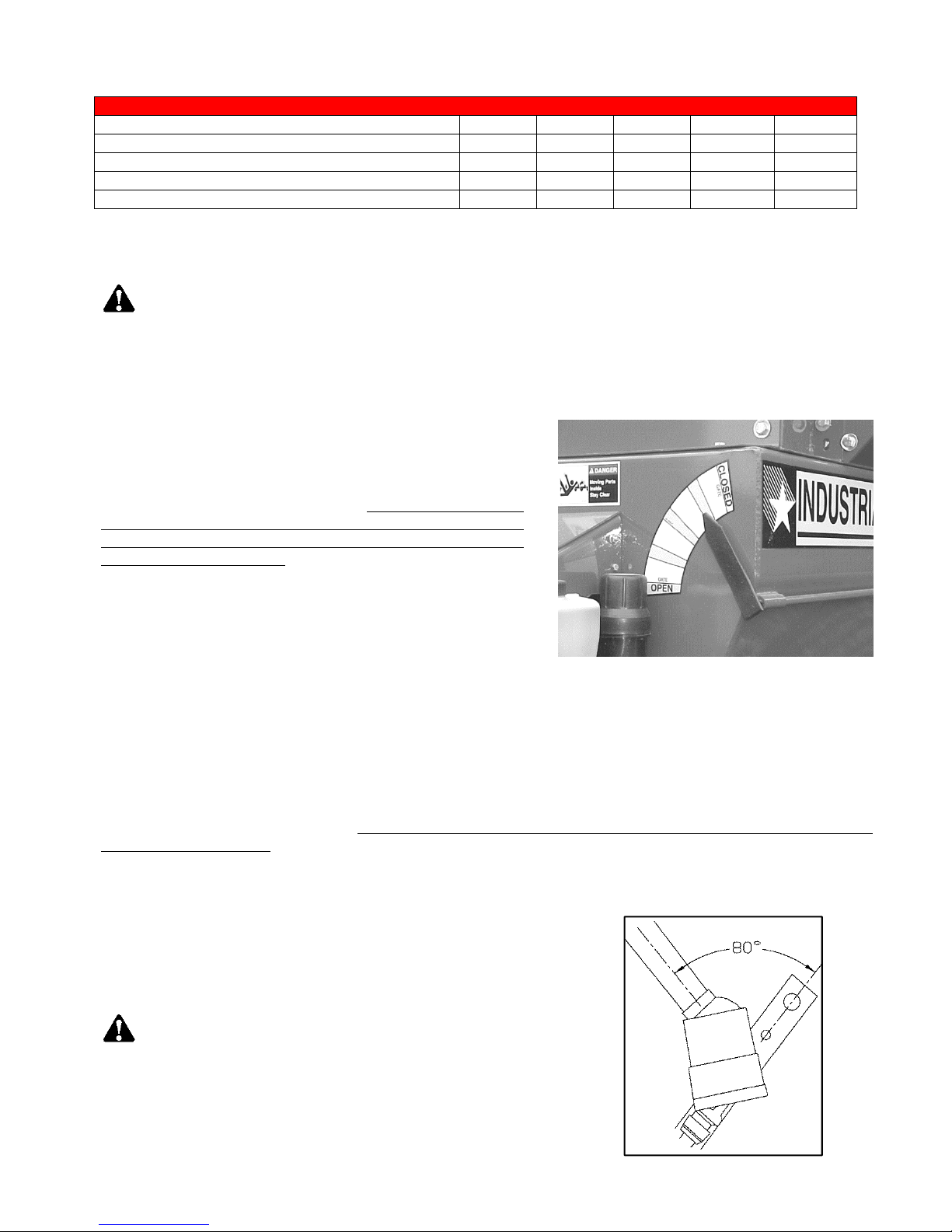
The first chain drive (PTO input shaft to the large RH
top sprocket, Figure 6) is automatically tensioned by a
spring loaded idler nylon roller. The extension spring
should extend 2” from its neutral 5” total length.
Manual adjustment for the automatic tensioning idler,
nylon roller assembly is located at the left rear of the
spreader’s front bearing mounting plate.
FIGURE 6. FIRST CHAIN DRIVE
FIGURE 7. SECOND CHAIN DRIVE
Model 8720 / 8865 -19-
The second chain drive (large RH top sprocket to the
large LH top sprocket, Figure 7) is automatically
tensioned by a spring loaded idler nylon roller. The
extension spring should extend 2” from its neutral 5"
total length.
Manual adjustment for the automatic tensioning idler,
nylon roller assembly is located at the left rear of the
spreader’s front bearing mounting plate.
The third chain drive is automatically tensioned by a
spring-loaded nylon idler roller. The compression spring
should be compressed to 4.5" in length. See Figure 8.
To increase tension on the automatic tightener, tighten
the adjuster bolt located at the left side of the spreader.
FIGURE 8. THIRD CHAIN DRIVE
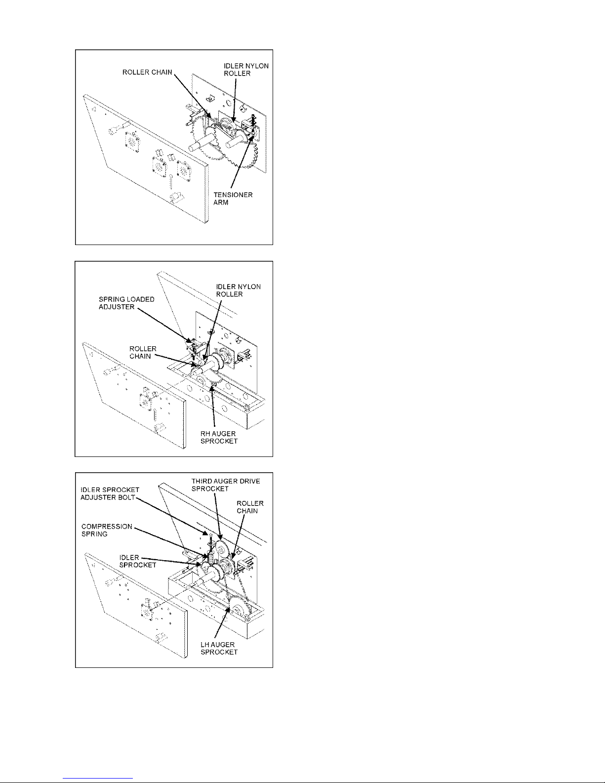
FIGURE 9. RH AUGER CHAIN DRIVE
The RH auger chain drive (Figure 9) is automatically
tensioned by a spring loaded idler nylon roller. The
compression spring should be compressed to 4.5" in
length. See Figure 9.
To increase tension on the automatic tightener, tighten
the adjuster bolt located at the right side of the spreader.
The LH and third auger chain drive is automatically
tensioned by a spring loaded heavy compression spring
and sliding idler sprocket assembly (Figure 10). The
heavy compression spring should be compressed to 4”
in length.
Manual adjuster bolt for the automatic tensioning idler
assembly is located slightly right of center on the
spreader tank.
FIGURE 10. LH & THIRD AUGER CHAIN DRIVE
Model 8720 / 8865 -20-
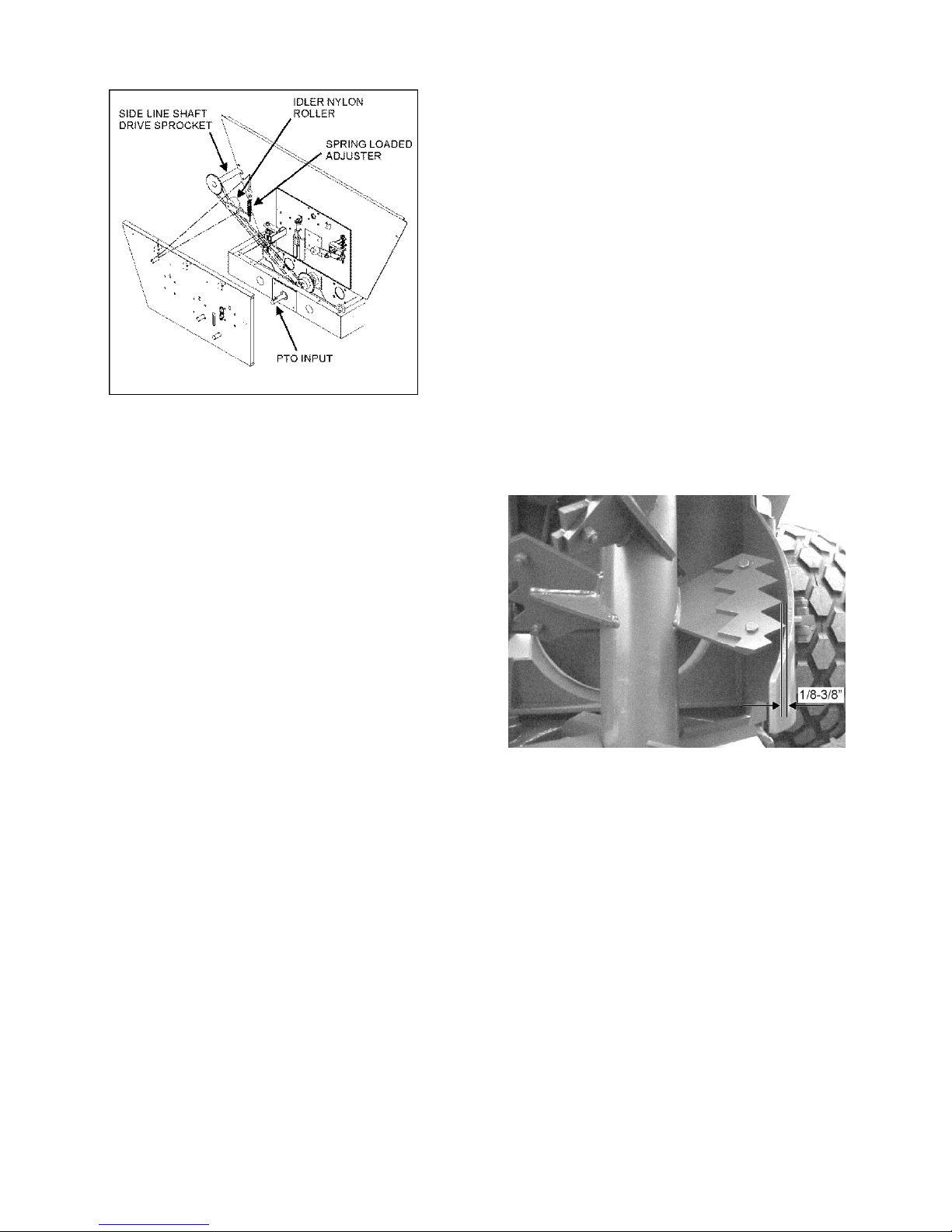
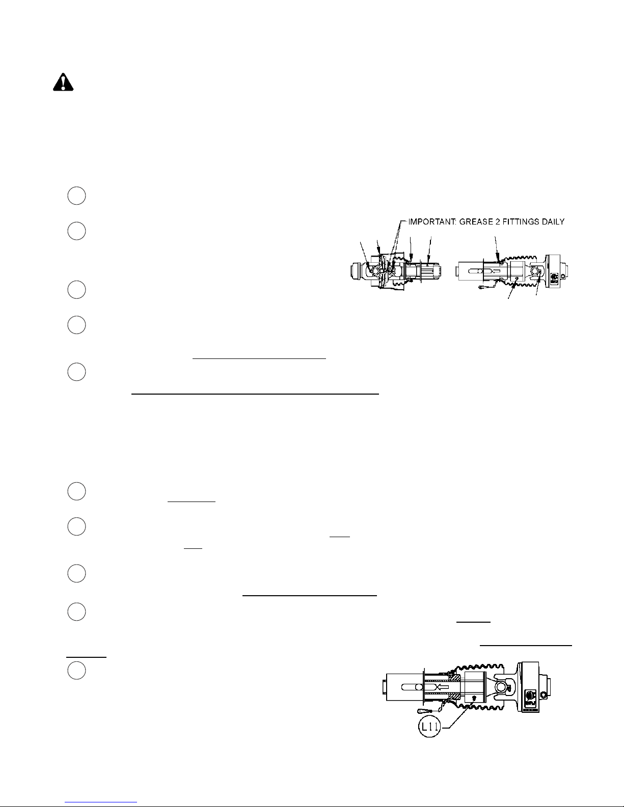
FIGURE 11. SIDE SHAFT CHAIN DRIVE
7.2. SPINNER MATERIAL GUIDES
Regularly inspect and adjust two spinner material
guides located at both the left rear and right rear of
the spreader. Create a 1/8-3/8” clearance between
material guides and spinner teeth (Figure 12).
Maintain the recommended clearances for
maximum spreading pattern. Adjust to prevent
excessive manure build-up on material guide inner
surfaces. Adjust to prevent manure chunks or
foreign object lodging between material guides and
spinner teeth.
NOTE: Excessive lodging can cause premature
spinner tooth wear, “bent-over” or even breakage.
The side shaft chain drive (PTO input shaft to the side line
shaft drive sprocket, Figure 11) is automatically tensioned
by a spring-loaded idler nylon roller. The extension spring
should extend 2" from its neutral 5" total length.
Manual adjustment for the automatic tensioning idler,
nylon roller assembly is located at the right rear of the
spreader’s front bearing mounting plate.
FIGURE 12. MATERIAL GUIDE CLEARANCE
7.3. SHEAR ARM MATERIAL GUIDE
Adjustment for the 1/8-3/8” clearance of each material guide to spinner tooth is made by loosening the jam nut
on the linkage arm and turning the linkage arm to either move the guide in closer or out farther from the spinner
teeth. After adjustment has been made for the 1/8”-3/8” clearance, retighten the jam nut to hold the material
guide in place. Once recommended clearance is obtained turn spinners over by hand in the direction by which
the spreader would turn to check clearance. Do not turn in the opposite direction as front chain tightener
damage could occur. If foreign objects enter the spinner area the front pivot bolt on the shear arm is designed to
shear. The extension spring will pull the material guide away from the spinner until the shear bolt is replaced.
The 1/2-13 x 3 1/2” grade 5 replacement machine bolts are stored under the rear shield. For replacement install
with 1/2” flat washer on top of shear eye and on bottom of block and tighten nylon locknut firmly.
Model 8720 / 8865 -21-
8. LUBRICATION
L1
L2
L3
L4
L5
L6
L7
L8
L10
L11
WARNING:
SERVICING THIS SPREADER. FAILURE TO HEED MAY RESULT IN SERIOUS PERSONAL INJURY OR
DEATH.
Note: Use a grease type that is composed of a high quality lithium complex or better, unless otherwise stated. We
recommend using a #1 grade in colder temperatures or a #2 grade in warmer temperatures.
8.1. DAILY LUBRICATION (EVERY 8-12 LOADS)
Grease (2) rear spinner lower bearings. These bearings are grease line fitted to the LR frame channel of
the spreader.
Oil (6) roller chain drives with automatic oiler at
the front of spreader with clean 30-weight oil. The
roller chains are accessible by opening the front steel
shielding cover.
Grease PTO Drive line (9) places with Lithium
grease every 8 hours.
Grease (7) bearings supporting the three large jack shaft reduction sprocket weldments and the third auger
drive shaft on the front drive. The zerks are accessible by the right front side grease bank and through the
access holes in front plate. Be careful not to over grease.
SHUTOFF AND LOCKOUT POWER BEFORE CLEANING, ADJUSTING, LUBRICATING OR
(Grease fitting on CV – some models only)
Grease (2) auger shaft bearings. These bearings are grease line fitted to the LF and RF frame channels of
the spreader. Over greasing is not possible (10-15 pumps minimum).
IMPORTANT: Check regularly for any observable lubricant leakage of the (3) gearboxes at the rear of the
spreader. See L12 & L14 under Monthly Lubrication.
8.2. WEEKLY LUBRICATION (EVERY 25-30 LOADS)
Grease (3) PTO input shaft bearings. These bearings are grease line fitted to the RF frame channel and
the front bearing channel of the spreader.
Grease (5) bearings on the RH side line shaft. The front bearing is zerk accessible through the RF steel
shielding. The remaining rear bearings are located along the RH side of the spreader tank, zerks accessible
through the steel shielding.
Grease (2) tandem wing pivots. Effectively grease by jacking up the spreader to relieve pressure points on
the pivot shaft and tandem wing collar. Over greasing is not possible.
Grease (2) flow control rear gate slide guides. With the flow control rear gate opened, grease the slide
guides from top side. Allow grease to lubricate flow control rear gate ends and slide guide surfaces. In freezing
weather dump used motor oil down each slide guide once a week or more often if needed. Over greasing is not
possible.
Grease (1) integral overrunning clutch at rear of the PTO
drive line. The zerk is on the yoke of the cut out clutch. Use a
high quality lithium complex grease.
Model 8720 / 8865 -22-
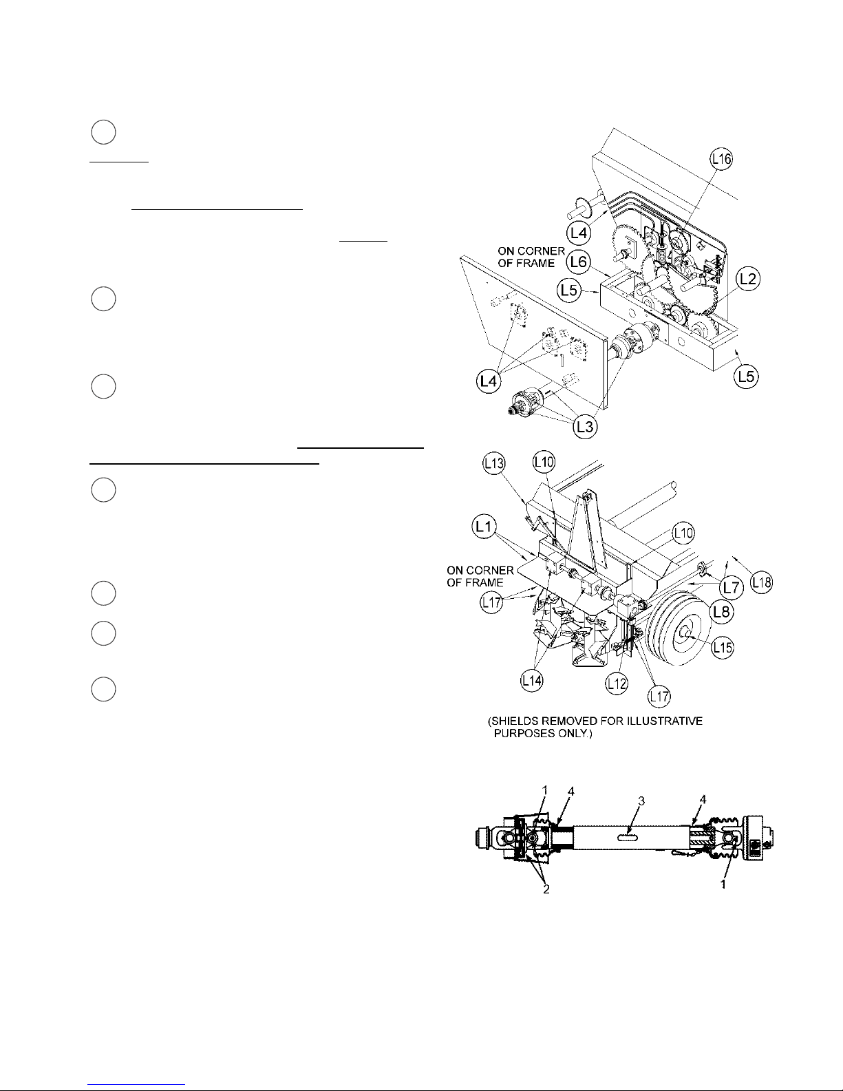
8.3. MONTHLY LUBRICATION
L12
L13
L14
L1
L16
L17
L18
Maintain oil level in the corner gearbox at the
centerline of the input shafts. Check regularly for any
observable oil leakage. If oil leakage is excessive,
replace required input/output shaft oil seals. Use
ONLY EP #80-90 wt. gear lube oil or an equivalent in
corner box, only Lighter weight gear lube oil may be
used in temperatures lower than 20°F. Change oil in
the gearboxes after the first season of use and
regularly thereafter.
Grease (1) nylon bushing supporting the rear
shaft of the 3rd auger assembly. This zerk is located
on the left rear corner of the tank above the inner
cross brace.
Maintain the lube level in the (2) spinner
gearboxes at 3/4 full. Check regularly for any
observable leakage. If leakage is excessive, replace
required input/output shaft seals. Lubricate with SemiFluid, EP Lithium Base, Gear Grease.
5
Clean and repack the wheel hubs with axle
grease annually. Grease hub through zerk in hub
monthly. Hub from factory has bearings packed but
hub is not fully loaded with grease. Be careful not to
over grease and force seal out of back side of hub.
Oil slides on front idler tightener assembly.
Grease (4) material guide pin sleeves. (2) located
on each side of the spreader.
Grease (2) T-post hold down sleeve zerks located
above the cross channel on the underside of the
spreader. A zerk is located on the front and one on the
rear of the sleeve.
8.4. PTO LUBRICATION
It is extremely important to follow the maintenance
guidelines. If telescoping members become hard to slide
during normal operation, it is recommended the shaft be
taken apart, cleaned with solvent and recoated with
grease before re-assembling. As a minimum it is important
this be done after each season of use.
8.4.1. LUBRICATION
A high quality lithium complex grease should be used.
FIGURE 13. PTO DRIVELINE MAINTENANCE
Model 8720 / 8865 -23-

8.4.1.1. Prior To Use
A. Using the CV Zerk (Key #2) place 20 pumps of grease into the CV center housing. This should be
done with the driveline / CV as straight as possible.
B. Slowly articulate the double joint through its maximum joint angle several times.
C. Return the CV joint to its straight position and insert additional grease into the CV Zerk (Key #2)
until grease is evident around the housing and center sliding disk.
8.4.1.2. Normal Operation
A. Lubricate the following items after every eight (8) hours of operation. If short rows and frequent
turning or other demanding conditions exist, lubricate at four (4) hour intervals.
1. Cross and bearings (Key #1)-Add grease until it is purged around the seals.
2. CV center housing (Key #2)-Add grease until it is evident around the center sliding disk.
3. Telescoping members (Key #3)-Add grease until it adequately covers the sliding members.
Take apart occasionally to make sure adequate lubrication is being added.
4. Shield bearings (Key #4)-Add 2-3 pumps.
FAILURE TO FREQUENTLY GREASE THE CV CENTER HOUSING AND TELESCOPING MEMBERS
WILL REDUCE THE LIFE OF THE CV.
8.5. AUTOMATIC CHAIN OILER
WARNING:
OR SERVICING THIS SPREADER. FAILURE TO HEED MAY RESULT IN SERIOUS PERSONAL INJURY
OR DEATH.
WARNING:
TO CAUSE INJURY. KEEP ALL HOSES AND CONNECTIONS IN GOOD SERVICEABLE CONDITION.
FAILURE TO HEED MAY RESULT IN SERIOUS PERSONAL INJURY OR DEATH.
The automatic chain oiler attachment gives a squirt of clean oil to all roller chains every time that the spreaders
rear gate, hydraulic cylinder is activated. In this way, the spreaders roller chains get oiled in direct proportion to
the number of hydraulic cylinder cycles of the rear gate. This assures adequate lubrication.
New 30 weight oil, which is placed in the reservoir tank mounted on the spreader, is all that is needed to
properly lubricate all roller chains and sprockets. The automatic chain oiler does not use any oil from the
tractor’s hydraulic system. The hydraulic hose connected to the bottom of the oiler pump only serves to power
the piston in the pump every time that the spreader’s rear gate is opened.
Should the oil reservoir tank run dry, pour about a 1/2 cup of
clean 30 weight oil into the tank. Allow time for the oil to run
down into the oiler pump slowly and allow air to escape. After
thirty minutes to one hour has passed, finish filling the reservoir
tank. Make sure that all fittings and brackets are tight when
finished filling the tank.
While running the tractors hydraulics only, open and close the
spreaders rear gate several times. This will cycle the hydraulic
cylinder leading to the oiler pump. Keep cycling until oil can be
seen in all of the oil lines leading to the oiler brushes. (If you
experience problems priming the oiler pump, you may need to
bleed air out of the hydraulic hose where it is connected to the
pump. Crack the fitting until oil comes out, and then re-tighten.)
The hydraulic cylinder that the oiler pump is tied into is double
acting and must reach 300 PSI of pressure to actuate the pump.
SHUTOFF AND LOCKOUT POWER BEFORE CLEANING, ADJUSTING, LUBRICATING
HYDRAULIC FLUID ESCAPING UNDER PRESSURE CAN HAVE SUFFICIENT FORCE
Model 8720 / 8865 -24-
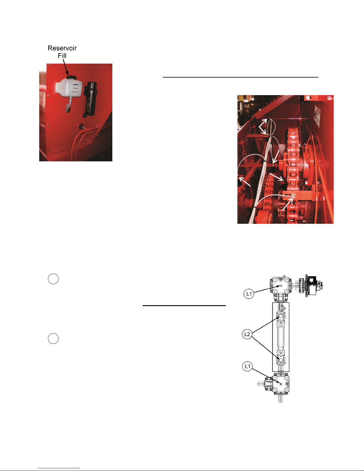
L1
L2
When replacing oiler brushes into brush holders, use regular 1/2"-20 nuts.
Tighten nut finger tight initially as some adjustment may be needed later. For
best results, place brush holders over top of roller chains and directly on top of
sprockets. Adjust brush holders so oiler brushes are pushed down into the
roller chain approximately 1/2". Carefully tighten up the 1/2"-20 nuts on the
oiler brushes. DO NOT over tighten as damage to the brush will occur. The
plastic threads of the oiler brush will crack and then break off from the brush
body.
IMPORTANT! The 5/32" oil line
tubing can only be removed from
an oiler brush by pushing in on
the red plastic ring and pulling the
tubing out while holding the ring
down.
The oiler pump is set at the factory to
deliver the maximum amount of oil
per cycle. If less oil is desired, loosen
the jam nut on the bottom of the
pump and screw in the adjusting shaft 1/4" or approximately 5 turns.
It is not recommended to screw the shaft into the bottom of the oiler
pump more than 15 turns as this may not allow for proper lubrication
of the roller chains.
IMPORTANT! Always use new 30 weight oil. In cold weather,
use a SAE 10 or a mixture of two parts of 30 weight oil to one
part diesel fuel.
8.6. TRUCK MOUNT MECHANICAL DRIVE, LUBRICATION OF (OPTIONAL)
8.6.1. MONTHLY LUBRICATION
Keep the upper and lower gearboxes 1/2 full of 75W90 Synthetic
oil, capacity approximately 125 oz. Check regularly for any
observable leakage. If leakage is excessive, replace required
input/output shaft seals as needed. Use only synthetic 75W90 oil.
8.6.2. DAILY LUBRICATION
Grease PTO driveline (2) places with lithium grease every 8
hours.
Model 8720 / 8865 -25-

9. STORAGE AFTER USE
WARNING
SERVICING THIS SPREADER. FAILURE TO HEED MAY RESULT IN SERIOUS PERSONAL INJURY OR
DEATH.
DANGER
SPINNERS BEFORE APPLYING POWER. FAILURE TO HEED MAY RESULT IN SERIOUS PERSONAL
INJURY OR DEATH.
Before storing this spreader for an extended period of time perform the following:
Allow the spreader to completely clean out the last load. Thoroughly hose off all manure from the outside of the
spreader and the inside of the box, particularly getting the flow control rear gate mechanism clean. The wash water
can be drained into your manure storage pit, or if the gate is left closed, the water can be spread on the field. After
cleaning, completely lubricate the entire spreader to exclude moisture from bearings and to prevent condensation
from forming during storage. See “Lubrication” pages, starting on page 22.
Oil the roller chains by running the spreader at idle speed while opening the rear gate to activate the automatic oiler
system. It is also a good time to inspect all adjustments and check for parts that need repair or replacement.
Performing these tasks now will guarantee that the spreader is ready for use at the beginning of the next season.
: SHUTOFF AND LOCKOUT POWER BEFORE CLEANING, ADJUSTING, LUBRICATING OR
: MAKE CERTAIN ALL PERSONNEL ARE CLEAR OF THE SPREADER AND THE ROTATING
Model 8720 / 8865 -26-

10. REPLACEMENT PARTS
10.1. INTRODUCTION
WARNING
OR SERVICING THIS SPREADER. FAILURE TO HEED MAY RESULT IN SERIOUS PERSONAL INJURY
OR DEATH.
WARNING
FAMILY MEMBERS ARE FAMILIAR WITH THE SPREADER AND THE SAFETY HAZARDS THAT ARE
PRESENT, ALONG WITH THE SAFETY PRACTICES THAT SHOULD BE OBSERVED WHILE WORKING
ON THIS EQUIPMENT.
Whenever adjusting, cleaning, lubricating or otherwise servicing this spreader, you must shutoff and lockout
power to the spreader. Because this spreader can be truck mounted or powered by a tractor, methods vary.
On truck mounted units, the connection between the truck and the spreader is permanently installed and not
intended to be disconnected. On trucks, disengage the PTO drive, turn off the engine, set the parking brake,
remove the ignition keys and keep them in your possession to prevent anyone else from accidentally applying
power to the box unexpectedly. For tractors, disconnect the PTO, disconnect and relieve pressure of the
hydraulics, turn off the tractor and set the brakes.
At times, parts on this equipment will become worn or damaged. Performing repairs on this equipment can
pose a risk of injury including death. To reduce risk, the party that will be doing the repair should be very
knowledgeable of the implement and the equipment that they will be using to do the repair.
• Review the repair so that a plan can be put together and the proper equipment can be used to repair
this implement safely and correctly.
• Personal safety equipment may include items such as safety glasses, protective footwear, hearing
protection, gloves, fire retardant clothes, etc.
• The use of hoists and/or supports may be needed to handle heavy components.
: SHUTOFF AND LOCKOUT POWER BEFORE CLEANING, ADJUSTING, LUBRICATING
: BEFORE SERVICING THIS PRODUCT, ENSURE THAT ALL PERSONNEL, INCLUDING
WARNING
WORK UNDER SUSPENDED OR BLOCKED PARTS.
• If the implement is being repaired in the field, make sure the parking brake of the tractor is engaged, the
implement is on solid and level ground.
• Welding and torching should be done by properly trained individuals who have proven their skills.
Throughout this manual, when directed to shutoff and lockout power, be familiar with the previously described
procedures for the type of machine you are operating.
IMPORTANT: Call the factory for any additional details you may need to perform the repair. Some parts may
come with instructions sheets to assist in your repair. Instruction sheets may be provided with your parts order.
Otherwise, if available, they can be e-mailed or faxed for your convenience. Meyer Manufacturing Corporation's
toll free number is 1-800-325-9103.
Be environmentally friendly and dispose of any waste materials properly. Recycle when appropriate.
DANGER
SAFETY SIGNS AND SAFETY LIGHTING REGULARLY. THESE PARTS OF YOUR IMPLEMENT, IF NOT
WATCHED CLOSELY, COULD POSE POTENTIAL INJURY INCLUDING DEATH. IF AN ITEM IS FOUND IN
NEED OF REPAIR, TAG THIS UNIT AS INOPERABLE AND HAVE QUALIFIED PERSONNEL REPAIR
IMMEDIATELY.
: WORKING UNDER SUSPENDED PARTS PRESENTS A CRUSH HAZARD. DO NOT
: INSPECT THE AXLES, O-BEAMS, SPINDLES, TIRES, HITCHES, SAFETY SHIELDING,
Model 8720 / 8865 -27-

10.2. CRACKS
The entire axle, o-beam, spindle and hitch should be visually inspected for cracks regularly. Any cracks found
will indicate immediate repair or replacement is necessary.
10.3. WORN COMPONENTS
Some parts will wear due to use. It is highly recommended to replace critical safety items such as a hitch that
has worn through the "Wear Plate" or is less than three quarters of its original thickness.
10.4. HYDRAULICS
WARNING
TO CAUSE INJURY. KEEP ALL HOSES AND CONNECTIONS IN GOOD SERVICEABLE CONDITION.
FAILURE TO HEED MAY RESULT IN SERIOUS PERSONAL INJURY OR DEATH.
Whenever working on any part of the hydraulics, safely relieve hydraulic pressure before starting.
: HYDRAULIC FLUID ESCAPING UNDER PRESSURE CAN HAVE SUFFICIENT FORCE
Model 8720 / 8865 -28-
 Loading...