

Meyer E-Z PLUS MDII STP-7.0, E-Z PLUS MDII STP-7.5 Installation Manual

Form 1-746 R
April, 2005
Parts & Installation Instructions
E-Z PLUS™/MDII™ Models STP-7.0 and STP-7.5
13
11
15
12
14
6
7
1
22
4
1
19
25
2
3
18
20
17
21
26
24
29
23
31
32
30
27
Parts List
28
8
3
16
14
2, 3
4
5
10
15
15
13
2
12
9
8
14
Item STP-7.0 Qty. STP-7.5 Qty. Description
09243 1 09244 1 Moldboard Assembly
1 12033 1 12475 1 • Moldboard Frame
2 12368 2 12368 2 • Rubber Insert Outside rib STP
3 12369 2 12369 2 • Rubber Insert Inside rib STP
4 12054 1 12474 1 • Plastic Sheet
5 12053 1 12471 1 • Snow Deflector
6 12030 1 12487 1 • Bar Reinforcement
7 12029 1 12491 1 • Angle Support
8 09132 1 09796 1 • Cutting Edge
9 08184 1 08184 1 • Bolt C 1/2-13 x 1-3/4” Gr. 5
--------- ---- ---------- ---- & Locknut (Kit of 9 each)
10 22193 8 22193 9 • Bolt H 3/8-16 x 1” Gr.2
11 22191 7 22191 6 • Bolt C 3/8-16 x 1” Gr. 1
12 22190 12 22190 14 • Bolt C 1/2-13 x 1-3/4” Gr. 5
13 20314 15 20314 1 5 • Locknut 3/8-16
14 20307 12 20307 1 4 • Locknut 1/2-13
15 20353 15 20353 2 4 • 3/8” Flatwasher
12070 1 12467 1 Snow Deflector Kit
16 09126 2 09126 2 • Runner & Spindle Assembly
17 07006 1 07006 1 • • Runner
18 20363 10 20363 1 0 • • Flat Washer 1-1/4”
19 22083 1 22083 1 • • Linch Pin
20 12057 1 12057 1 • • Spindle
21 20101 1 20101 1 • • Bolt H 1/2-13 x 3”
22 20307 1 20307 1 • • Locknut 1/2-13
16515 1 16515 1 Sector and A-Frame Carton
23 21534 2 21534 2 • Lift Chain 5/16 x 36”
24 12326 1 12326 1 • Sector
25 13711 1 13711 1 • A-Frame (11” x 34” x 22-1/8”)
26 07017 3 07017 3 •• Trip Spring
09916 1 09116 1 • Plow Marker Kit
08738 1 08738 1 • Hardware Bag
27 09119 2 09119 2 •• Pivot Pin w/Fttg.& Cotter Pin
28 09124 3 09124 3 •• Eye Bolt w/ Locknut & Cap
29 09122 1 09122 1 •• King Bolt w/ Locknut
30 8518001026 2 8518001026 2 •• 7/16-14 NC U-Bolt
31 8501001007 4 8501001007 4 •• 7/16-14 NC Nut
32 20328 4 20328 4 •• Lockwasher
Parts indented are included in the assembly under which they are indented.
Meyer Products reserves the right, under its continuing product improvement program, to change construction or design details,
specifications and prices without notice or without inncurring any obligation.
INSTALLATION INSTRUCTIONS
Note: The following instructions cover assembly of
Moldboard, Sector and A-Frame. Refer to separate
instructions for installation of plow mounting and hydraulic
system.
A. Liberally coat Pivot Pins (27) with chassis lubricant.
B. Attach Sector (24) to Moldboard (1) with Pivot Pins (27)
(grease fitting facing outward) and insert Cotter Pin.
Grease Pivot Pin using grease fitting.
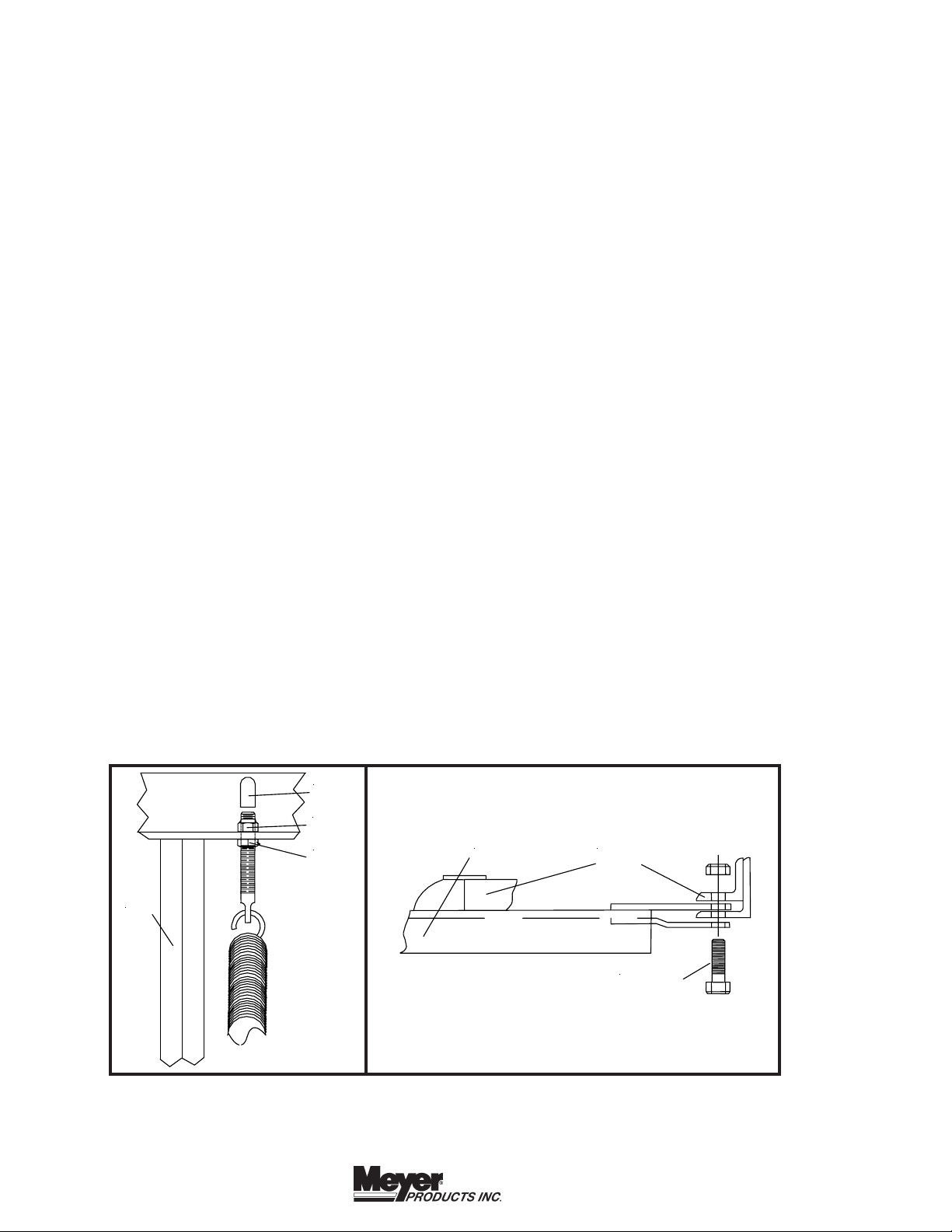
C. Attach Eye Bolts (28) to Moldboard (1) and trip Springs
(26) to Sector (24), making certain locknuts (28) are
positioned as shown in Figure 1.
D. Make certain each Eye Bolt (28) is in a vertical position
as shown in figure 1 so that the Eye Bolt (28) and Trip
Spring (26) hinge properly when moldboard trips.
Note: Proper tension is attained when Trip Spring (26) coils
just begin to separate and then tightening top locknut four
additional turns. Tighten bottom Locknut (20530) to secure
Eyebolt in position. Install Eyebolt caps (07031) over
exposed threads. See Figure 1.
RIB
E. Attach A-Frame to Sector (24) as shown in Figure 2.
IMPORTANT: Install King Bolt (29) from bottom so that
locknut is on top.
07031
20309
20530
A-Frame Sector
King Bolt
© 2005 Printed in the U.S.A.
Figure 1
Figure 2
18513 Euclid Ave. • Cleveland, Ohio 44112-1084
Phone 486-1313 (Area Code 216)
email warranty@meyerproducts.com
www.meyerproducts.com
 Loading...