

Page 1
PARTS & INSTALLATION INSTRUCTIONS
MDII™and EZ MOUNT PLUS™
SNOW PLOW MOUNTING 17195
2017 & Later FORD F250 thru F550
4x4 MODELS
Snow Plow Preparation Package 86M
End user must be given this instruction sheet prior to delievery of this Snow Plow.
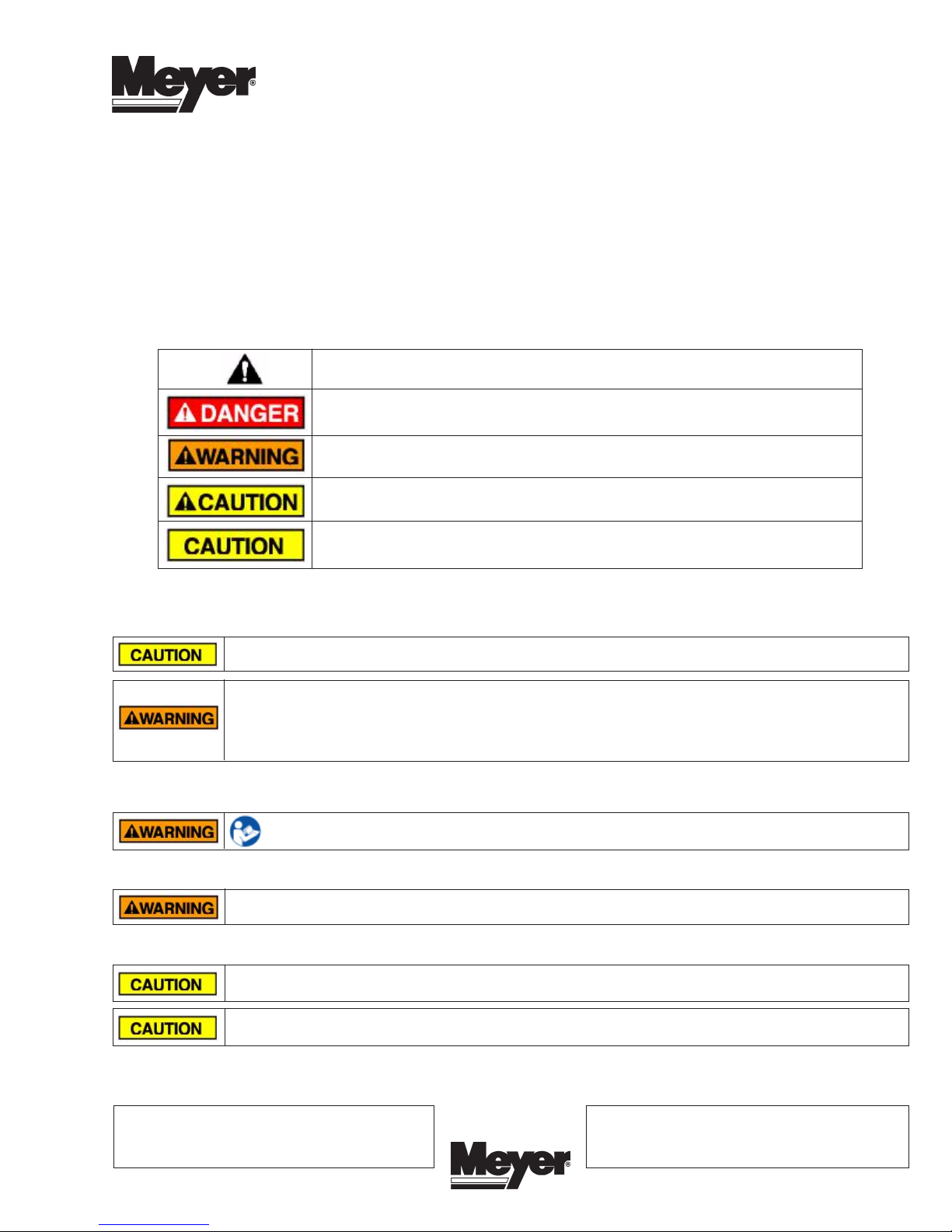
SAFETY DEFINITIONS
This is the safety alert symbol. It is used to alert you to potential personal injury hazards.
Obey all safety messages that follow this symbol to avoid possible injury or death.
DANGER Indicates an imminently hazardous situation which, if not avoided, will result in
death or serious injury.
WARNING Indicates a potentially hazardous situation which, if not avoided, could result
in death or serious injury.
CAUTION Indicates an potentially hazardous situation which, if not avoided, may result in
minor or moderate injury.
Form 1-1151
July 2016
CAUTION used without the safety alert symbol indicates a potentially hazardous situation
which, if not avoided, will result in property damage.
IMPORTANT NOTICE
In conjunction with FMVSS (Federal Motor Vehicle Safety Standards) and OEM (Original Equipment Manufacturer) guidelines,
Meyer Products has designed this plow package with the following guidelines:
Installation of a snowplow may effect your new vehicle warranty.
For more information consult your Vehicle Owner's Manual / Vehicle Dealer.
The vehicle must not be operated when overloaded. In all cases, the loaded vehicle weight, including the entire
snowplow system, all aftermarket accessories, driver, passenger, options, nominal fluid levels, and cargo must not
exceed the front/rear Gross Axle Weight Rating (GAWR), and total Gross Vehicle Weight Rating (GVWR). These
weights ratings are specified on the safety compliance certification label on the driver's side door opening. The use
of rear ballast weight may be required to prevent exceeding the front GAWR.
According to the NHTSA (National Highway Traffic Safety Administration) new and untitled vehicles need to be verified by the installer that
snowplow and ballast (if needed) do no exceed the front/rear GAWR and total GVWR.
Read the Meyer Owner's Manual before operating or servicing a snowplow. FOLLOW THESE INSTRUCTIONS
EXPLICITLY.
GENERAL INFORMATION
SAFETY PRECAUTIONS should be used when Hydraulic Unit is in OPERATION and plow is in a RAISED
position. Lower plow to ground when vehicle is PARKED in case of hydraulic failure.
Check contents against the parts list to determine all are correct and included, and also to familiarize yourself with them.
Warranty does not apply to a Meyer or Diamond product which has been negligently or improperly assembled or
installed.
CAUTION: To avoid harm to vehicles electrical system always disconnect battery before beginning installation.
DO NOT BURN holes or WELD vehicle frame. This may cause frame failure.
OVERHAUL and SERVICE INFORMATION are covered on separate instructions.
Meyer Products LLC reserves the right, under its continuing product improvement program, to change construction or design details,
specifications and prices without notice or without incurring any obligation.
Meyer Products LLC
18513 Euclid Ave. • Cleveland, Ohio 44112-1084
Phone 486-1313 (Area Code 216)
www.meyerproducts.com• email info@meyerproducts.com
© 2016 Printed in the U.S.A.
6 Angell Lane • Damariscotta, ME 04543-4507
Meyer Products LLC
Phone 563-2227(Area Code 207)
www.meyerproducts.com• email info@meyerproducts.com
Page 2
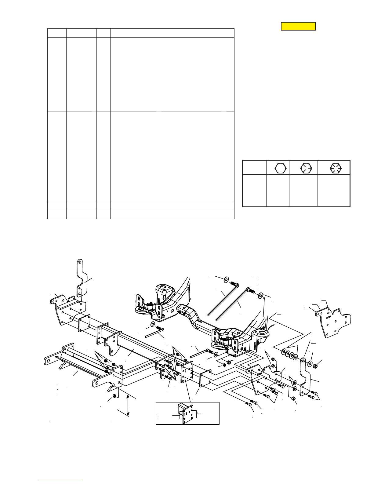
PARTS LIST
ITEM PART NO. QTY. DESCRIPTION
17195 1 MOUNTING CARTON
1 18985 1 • R.H. Side Assembly
2 18986 1 • L.H. Side Assembly
3 19807 1 • Rear Brace Weldment
4 18987 2 • Strap
5 19821 2 • Handle Bolt (16") 3/4-10 x 2-1/4" Gr.5
6 19823 2 • Handle Bolt (8") 5/8-11 x 2" Gr.5
7 19995 2 • Spacer 1/4"
08135 1 • Hardware Bag
8 20096 18 •• Bolt H 1/2-13 x 1-3/4” Gr. 5
9 20141 4 •• Bolt H 5/8-11 x 2” Gr. 5
10 20307 22 •• Locknut ESNA 1/2-13
11 20309 6 •• Locknut ESNA 5/8-11
12 20310 2 •• Locknut ESNA 3/4-10
13 20357 2 •• Flatwasher 5/8”
14 20359 12 •• Flatwasher 3/4"
15 11291 4 •• Spacer
16 20097 4 •• Bolt H 1/2-13 x 2" Gr. 5
* 19370 1 Universal Clevis (Part of Plus CLF Carton)
** 11770 1 Universal Clevis (Part of MDII CLF Carton)
Parts indented are included in the carton, bag or assembly under which
they are indented.
CAUTION
CAUTION: To avoid harm to vehicles
electrical system always disconnect battery
before begining installation.
DO NOT BURN holes or WELD vehicle frame.
This may cause frame failure.
IMPORTANT
After first use, retighten all mounting bolt
connections to specified torque. All mounting
bolt connections to be checked periodically
for tightness.
Locknuts are furnished DO NOT tighten bolts
and nuts until installation is complete (unless
otherwise specified), then be sure to tighten
all attaching parts per specified torque chart.
TORQUE CHART FOOT
Bolt Nut Size Gr. Gr. Gr.
1/4 - 20 4 - 5
5/16 - 18 9 - 11
3/8 - 16 17 - 20 26 - 29
7/16 - 14 42 - 46 60 - 66
1/2 -13 64 - 72 90 - 100
5/8 - 11 127 - 141 179 - 198
THIS MOUNTING CARTON CAN BE USED WITH
THE MDII OR EZ MOUNT PLUS CLF CARTONS.
2 5 8
NOTE:
1
Clevis Frame
*
packed in CLF
Carton
FIGURE 1
10
Add spacer Flatwashers (15) as needed
11
**
until Stra p (4 ) clears the s ta b iliz e r b a r.
Due to vehicle frame variances, the quantity
of spacer Flatwashers required may vary .
14
5
D
10
2
14
C
B
A
**
D
14
12
4
14
5
13
6
10
3
6
13
10
15
8
4
9
8
8
11
16
11
11-1/4"
GROUND
SPRING CODE "x"
6,000 lb.
Front g.a.w.r.
7
SPRING CODE "V"
5,200 lb.
Front g.a.w.r.
8
8
Page 3

VEHICLE RECOMMENDATIONS
• A ballast weight may be required to prevent front GAWR
overloading. If required, ballast must be securely attached
at least 18 inches behind the rear axle.
E. Attach lower holes of the L.H. & R.H. Straps (4) to
L.H. and R.H. Side Assembly (1 & 2)using
1/2-13 x 2" bolt (16), Spacers (15) (if necessary) and
locknut (10). Snug all bolts during installation. Do
not tighten at this time.
• Front end wheel alignment and headlight aim may require
readjustment after installation of equipment, and is the
responsibility of the equipment installer. Failure to adjust
front wheel alignment may cause premature uneven tire
wear. If required, reset to chassis manufacture’s
specifications found in the Ford Shop Manual.
• Rear ballast is determined by weighing a vehicle's front
and rear axles and adding weight behind the rear axle
until front axle weight is under or equal to the vehicle
specific front GAWR while not exceeding the rear
GAWR and GVWR.
• Vehicle option packages may vary. If in doubt, it is
always a good idea to weigh the vehicle to ensure all
weight ratings are not exceeded with plow in the raised
position.
INSTALLATION INSTRUCTIONS
A. Remove bumper and retain Hardware. They will be
reused.
B. Position L.H. Side Assembly (2) onto driver's side of
vehicle frame aligning the top three holes in Side
Assembly (2) with existing holes in vehicle frame.
Atttach Side Assembly (2) to vehicle frame at hole (A)
using 1/2-13 x 1-3/4" bolt (8) and Locknut (10). At
Hole (B) using 5/8-11 x 2" bolt (9) and Locknut (11).
At Hole (C) using Handle Bolt (6), flatwasher (13) and
locknut (11). Per illustration. Snug all bolts during
installation. Do not tighten at this time.
F. Position the Rear Brace Weldment (3) between the
L.H. & R.H. Side Assembly (1 & 2). Use Spacer Plate
1/4" (7) on driver side or both sides only if necessary
(Vehicle frame variances). Attach Rear Brace Weldment
to Side Assemblies (1&2) using 1/2-13 x 1-3/4" bolt
(8), locknut (10). Snug all bolts during installation.
Do not tighten at this time.
REAR BRACE WELDMENT (3) CAN BE ADJUSTED UP
OR DOWN between Side Assembly (1&2).
Match vehicle Spring Code Information with hole locations
in figure 2. Information on Spring codes can be found in
the lower right hand corner of tag located in the driver's
side door jam. Example: V/B or X/B.
NOTE: 2011 & later Diesel equipped vehicles may need
to use spring code X mounting location to avoid
interference with vehicle power steering cooler.
Spring Code V= 5200 lb Front g.a.w.r.
Spring Code X= 6000 lb Front g.a.w.r.
Spring Code
"X"
Spring Code
"V"
C. Follow same procedure when mounting R.H. Side
Assembly (1) to passenger side of vehicle frame.
D Position L.H. & R.H. Straps (4) to L.H. and R.H. Side
Assembly. Loosely attach lower holes of the L.H. &
R.H. Straps (4) to L.H. and R.H. Side Assembly. Mark
top hole in L.H. & R.H. Straps (4) to Hole (D) on both
the driver and passenger side of vehicle frame. Drill a
3/4" hole only on the outside of the vehicle frame at
hole (D). Attach strap (4) per illustration using Handle
Bolt (5), flatwasher (14) to inside of frame rail. If
necessaryspace out strap (4) using flatwashers (14)
behind Strap (4), and locknut (12). See ** note on
Figure 1.
Snug all bolts during installation. Do not tighten
at this time.
FIGURE 2
Meyer Products assumes no responsibility for installations
not made in accordance with these instructions.
 Loading...