

Meyer ELECTRO LIFT E-46, ELECTRO LIFT E-46H, ELECTRO LIFT E-47, ELECTRO LIFT E-47H, ELECTRO LIFT E-57 Service Manual
...
FORM NO. 1-562-R16
October, 2005
Price: $4.25
ELECTRO LIFT
power units
service manual
MODELS
®
E-46, E-46H
E-47, E-47H
E-57, E-57H
18513 Euclid Ave. • Cleveland, OH 44112-1084
Meyer Products Inc.
Phone (216) 486-1313
email•warranty@meyerproducts.com
© 2005 Printed in the U.S.A.
6 Angell Lane• Damariscotta, ME 04543-9720
Diamond Equipment
Phone (207) 563-2227
www.diamondplow.com • email info@diamondplow.com

FOREWARD
This Service Manual includes complete information for servicing the following Electro Lift® Units:
E - 46 and E - 46H
E - 47 and E - 47H
E - 57 and E - 57H
IMPORTANT: Maintenance and repairs must be performed with the moldboard on the ground.
The information is grouped according to the type of work being performed, such as diagnosis and testing,
disassembly and reassembly. Special tools and specifications are also included in this manual.
All information, illustrations and product descriptions contained in this manual are correct at publication
time. We do, however, reserve the right to make changes at any time without prior notice.
MEYER PRODUCTS INC.
SECTION INDEX
Section Number Section Title ..................................................... Page
0 GENERAL INFORMATION AND
MAINTENANCE ........................................................ 1
1 GENERAL DESCRIPTION AND
THEORY OF OPERATION ........................................ 4
2 DIAGNOSIS ............................................................. 23
3 REPAIR PROCEDURE .............................................. 30
4 SPECIFICATIONS ..................................................... 53
Meyer Products Inc. reserves the right, under its continuing product improvement program, to change construction or
design details, specifications and prices without notice or without incurring any obligation.

SECTION 0 - GENERAL INFORMATION AND MAINTENANCE
CONTENTS
GENERAL INFORMATION .................................................. 2
•M
ODEL IDENTIFICATION .................................................... 2
•M
ODEL IDENTIFICATION AND
SERIAL NUMBER LOCATION .............................................. 2
•M
OTOR IDENTIFICATION ................................................... 2
MAINTENANCE ................................................................... 2
•G
ENERAL MAINTENANCE ................................................... 2
•C
LEANLINESS ................................................................. 2
•V
EHICLE ELECTRICAL SYSTEM ........................................... 3
•C
HECK REGULARLY ......................................................... 3
POST-SEASON MAINTENANCE ....................................... 3
•M
EYER HYDRAULIC FLUID M-1 ......................................... 3
•R
EPLACEMENT OF HYDRAULIC FLUID ................................... 3
•F
ILTERS ........................................................................ 3
•P
ROTECTION AGAINST RUST
AND
CORROSION ............................................................ 3
-1-
GENERAL INFORMATION
R
Model Identification
®
The Electro Lift
unit is an electrically powered hydraulic
mechanism specifically designed for use with the Meyer
Snow Plow and is available in four models as follows:
E-46 Raises and lowers plow hydraulically
(2-way) and is used with TM, ST and
C series Snow Plows.
E-46H Raises and lowers plow hydraulically
(2-way) and is used with HM series
Snow Plows.
E-47/E-57 Raises, lowers and angles plow
hydraulically (7-way) and is used with
TM, ST and C series Snow Plows.
E-47H/E-57H Raises, lowers and angles plow
hydraulically (7-way) and is used with
the MDII, HM and Diamond series
Snow Plows.
Model Identification and Serial Number Location
Inclusion of the model number and serial number is
extremely important when writing up warranty claim
forms and product report forms for proper evaluation
and follow up.
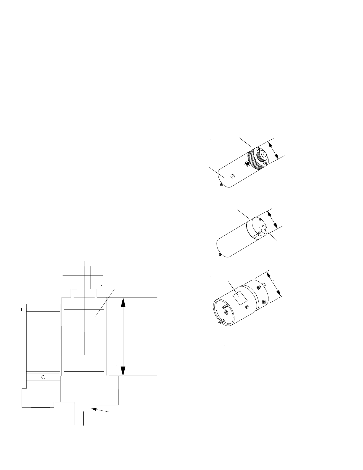
Motor Identification
Three different brand motors are used on the Electro
Lift® units American Bosch, Prestolite and Iskra.
Proper identification of the brand and supplier part
number is necessary when seeking local parts and
service sources.
The motor with which a specific Electro Lift® unit is
equipped can be identified by the distinctive
characteristics shown in figure 0-2.
DOMED COMMUTA T O
END COVER
STEEL ST AM PED
PRESTOLITE
MKW -4007-12V
FLAT COMMUT ATOR
END COVER
E
T
I
L
O
T
S
E
R
P
3" Dia.
3" Dia.
The basic model number is located on the name plate
located as shown in Figure 0-1. To determine whether
it is the standard or “H” model, measure the dimension
shown in Figure 0-1. The serial number is located on
the bottom of the base or on the name plate.
NAME PLATE
"
8
/
1
-
8
H
7
5
E
,
H
7
4
E
,
H
6
4
E
"
4
/
1
-
6
7
5
E
,
7
4
E
,
6
4
E
STEEL ST AMP ED
AMERICAN BOSCH
MO 551046A
ISKRA
Label 15829
AMJ4739 12V 1,6kw
SINGLE and TWO TERMINAL
4-1/2" Dia.
FIGURE 0-2
MAINTENANCE
The following maintenance information is intended as
a basic guide for providing the Electro Lift
®
unit with
the proper service and care. Sustained heavy duty
operation or operating under adverse conditions may
necessitate more frequent servicing.
xxxxx
FRONT VIEW
SERIAL NUMBER
(ON FRONT SIDE)
FIGURE 0 -1
General Maintenance
Cleanliness
The greatest enemy to any hydraulic system is dirt or
contamination. Therefore, cleanliness must be stressed
at the time of installation, servicing and repairing.
-2-
Vehicle Electrical System
Maximum performance and efficiency of the Electro
Lift® unit requires that the vehicle’s electrical system
be properly maintained and consist of:
Battery ----------- 70 Amp. Hr. Minimum or
550 Cold Cranking Amps.
Alternator ------ 60 Amp. Minimum
Check Regularly
1. Battery Terminals - Must be clean and free of
corrosion.
2. Electrical Connections - Must be free of corrosion
and tight.
3. Battery - Must be in first-class condition.
4. Alternator (or Generator) and Regulator - Must be
functioning to specifications.
5. Hydraulic Fluid Reservoir Level - A significant drop
in hydraulic fluid level indicates a leak which must
be located and corrected. Insufficient hydraulic fluid
may result in severe damage.
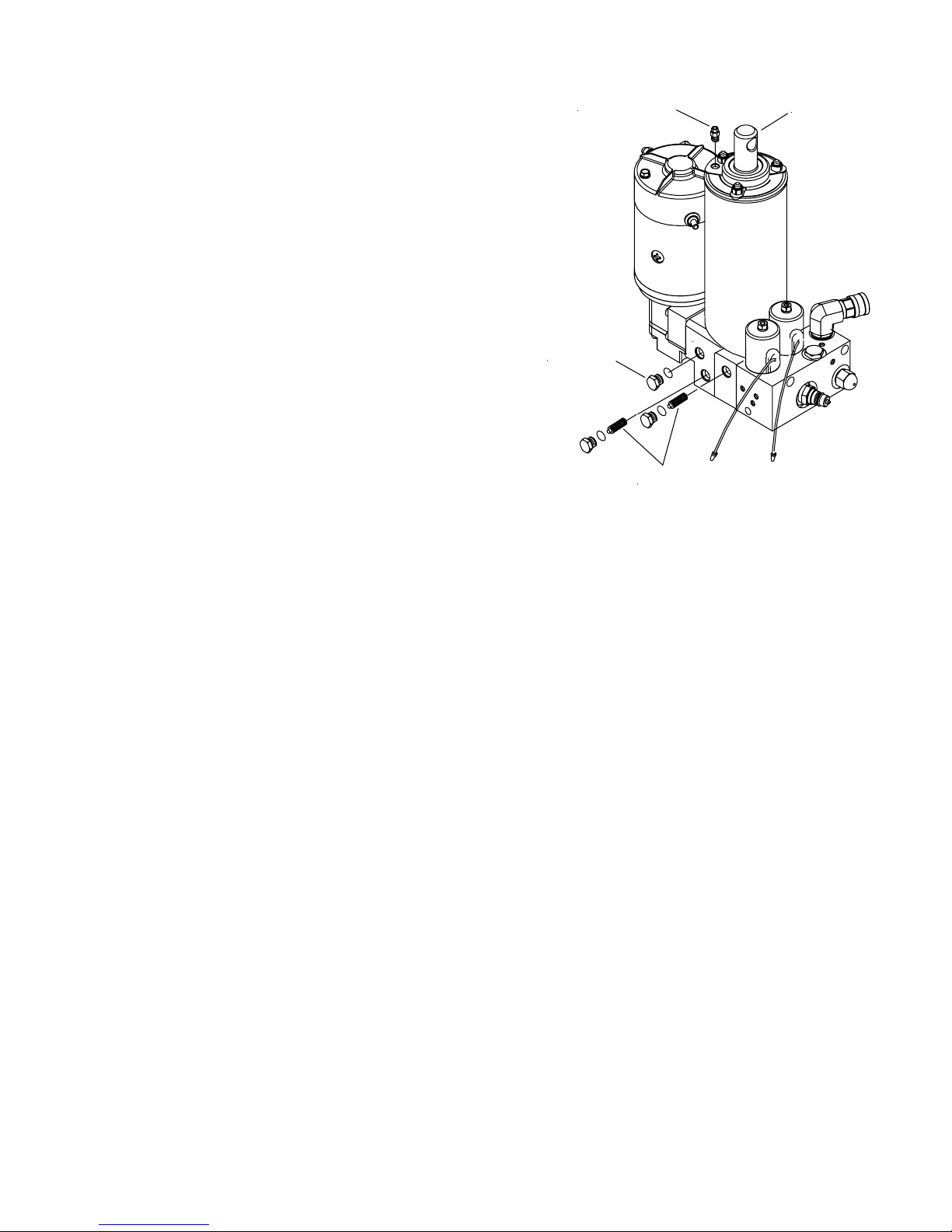
POST-SEASON MAINTENANCE
Meyer Hydraulic Fluid M-1.
FILLER PLUG
DRAIN PLUG
FILTER S
FIGURE 0-3
LIFT ROD
D
R
A
I
N
Meyer Hydraulic Fluid M-1 is a specially formulated
mineral oil which maintains an almost constant
viscosity from normal to sub-zero temperatures.
Because it remains free flowing at extremely low
temperatures, the performance and efficiency are not
affected.
Meyer Hydraulic Fluid M-1 also contains an additive
which neutralizes moisture accumulating in the fluid
due to condensation. It is effective for a maximum of
one year’s use.
Meyer Products Inc. will not be liable for damages
resulting from the use of inferior or other fluids or
oils.
Replacement of Hydraulic Fluid
After a season’s use, completely drain the hydraulic
fluid (including hydraulic fluid in hoses and cylinders
on Power Angling models). Drain fluid through filler
hole shown in Figure 0-3 or drain hole in base by
completely retracting lift rod and unbolting unit to pour
fluid out or using a suction pump. On Power Angling
models, disconnect the fittings at the Angling cylinders,
completely retract the cylinder rods and purge
cylinders and hoses of all hydraulic fluid. Flush the
complete system including unit, hoses and Power
Angling rams with a non wax (Napthenic) cleaner. If
kerosene (Parrafinic) is used to flush the system, the
system must be flushed again to remove any kerosene
with a (Napthenic) based cleaner that is wax free .
Refill Electro Lift
®
unit with M-1 Fluid by fully
retracting lift rod (Ram) and filling reservoir to 1-1/2
“ below the filler hole. On Power Angling models,
fill and bleed hoses and Power Angling cylinders
by loosening hydraulic fittings at cylinders until they
leak. Power angle plow repeatedly from one side to
the other until fluid flows steadily from the leaking
fittings while maintaining a constant check on the
reservoir fluid level.
Raise and lower the plow several times and with lift
rod fully retracted, give a final check to the fluid level
and replace filler plug.
Filters
Clean the two filters (only one in E-46 and E-46H; two
in Power Angling units) located in base of unit with
mineral spirits or equivalent and blow out with
compressed air. See Figure 0-3 for filter locations.
Protection Against Rust and Corrosion
When the Electro Lift® unit is not used for extended
periods, protect the chromed lift rod (Ram) by fully
extending it and coating it with chassis lubricant. Full
extension of the lift rod (Ram) fills the cylinder with
hydraulic fluid. On Power Angling models, coat the
exposed portions of the Power Angling cylinder rods
(Rams) with chassis lubricant to protect them against
rust and corrosion.
-3-

SECTION 1 - GENERAL DESCRIPTION AND THEORY OF OPERATION
CONTENTS
GENERAL DESCRIPTION ................................................................................................. 5
THEORY OF OPERATION................................................................................................. 5
UNCTIONS .................................................................................................................. 5
•F
•• Models E-46 and E-46H ................................................................................... 5
•• Models E-47, E-47H and E-57, E-57H ........................................................... 5
•ELECTRICAL AND FLOW CHARTS ...................................................................................... 6-18
ELECTRO LIFT® UNIT COMPONENTS ......................................................................... 19
•M
OTORS ...................................................................................................................... 19
•• American Bosch ............................................................................................... 19
•• Prestolite ............................................................................................................ 19
•• Iskra .................................................................................................................... 19
YDRAULIC PUMP .......................................................................................................... 19
•H
•P
RESSURE RELIEF VALVE ................................................................................................ 19-20
OLENOID VALVES ......................................................................................................... 20
•S
•• Cartridge ............................................................................................................ 20
•• Coil...................................................................................................................... 20
“A” Solenoid Valve............................................................................................. 20
“B” Solenoid Valve............................................................................................ 20
“C” Solenoid Valve ........................................................................................... 20
•CHECK VALVES .............................................................................................................. 21
•P
ILOT CHECK VALVE ...................................................................................................... 21
•C
ROSSOVER RELIEF VALVES ............................................................................................ 21
WITCH (MODELS E-46 AND E-46H) ............................................................................ 21
•S
•S
WITCHES (POWER ANGLING MODELS) ............................................................................ 21
•• Dual Switch Control ........................................................................................... 21-22
•• Single Lever Control .......................................................................................... 22
•• Electro-Touch Control......................................................................................... 22
•S
OLENOID SWITCH ........................................................................................................ 22
ILTERS ....................................................................................................................... 22
•F
-4-

GENERAL DESCRIPTION
THEORY OF OPERATION
Electro Lift® unit is an electrically powered and
electrically controlled hydraulic mechanism specifically
designed for use with Meyer Snow Plows. The standard
model E-46 raises and lowers the plow hydraulically
with an integral 6" stroke hydraulic cylinder while the
model E-46H performs the identical task for larger plows
with an integral 8" stroke hydraulic cylinder.
In addition to raising and lowering the plow
hydraulically, the model E-47, E-47H and
E-57, E-57H angles the plow hydraulically, left and
right, via remote hydraulic cylinders.
The Electro Lift® unit consists of a specially designed
high torque 12-volt DC motor which is directly coupled
to a gear-type hydraulic pump. The pump obtains its
supply of hydraulic fluid from an integral reservoir which
totally surrounds the integral hydraulic cylinder which
raises and lowers the plow.
Included in all models is an electrically controlled and
powered solenoid valve cartridge “A” which is
energized to allow the plow to lower by gravity.
The models E-47 and E-57 include an integral valve
body which contains two additional electrically
controlled solenoid valve cartridges. Solenoid valve
cartridge “B” is energized to route the pressurized
hydraulic fluid to the integral hydraulic cylinder to raise
the plow. Solenoid valve cartridge “C” is energized to
route the pressurized hydraulic fluid to the left remote
hydraulic cylinder to angle the plow to the right. Angling
the plow to the left only requires energizing the electric
motor since the normal route for the pressurized
hydraulic fluid is to the right remote hydraulic cylinder.
FUNCTIONS
®
The Electro Lift
models perform basic functions.
Because certain of these basic functions are
accomplished differently in the models E-46 and
E-46H as opposed to the Power Angling models will
be treated separately where necessary.
Models E-46 and E-46H
The two basic functions performed are:
• Raise snow plow
• Lower snow plow and float
Refer to Figures 1-1 and 1-2 (pages 6 thru 9) for
electrical and hydraulic flow chart for each function.
Each figure explains which component is actuated and
related in each function.
Models E-47, E-47H and E-57, E-57H
The four basic functions performed are:
• Raise snow plow
• Lower snow plow
• Angle snow plow to right
• Angle snow plow to left
Refer to Figures 1-3 through 1-6 (pages 6 thru 18) for
electrical and hydraulic flow chart for each function.
Each figure explains which component is actuated and
related in each function.
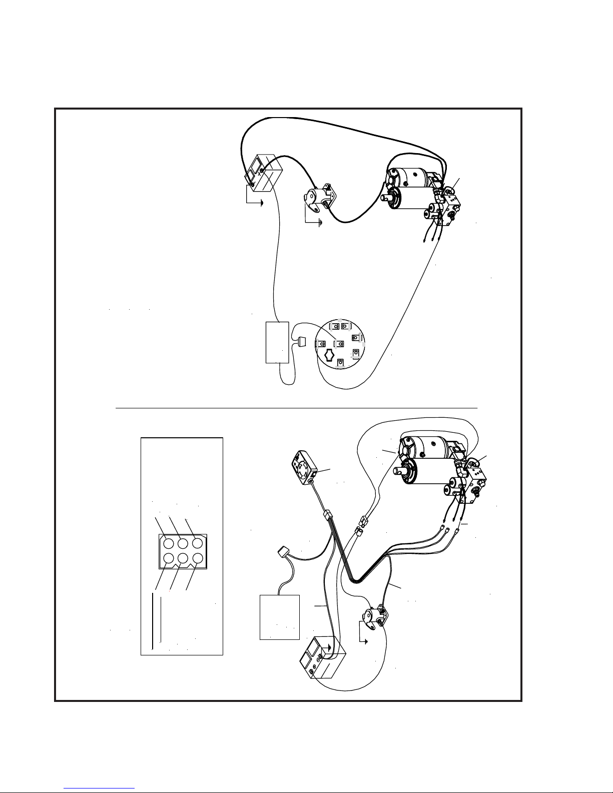
Additional components which control and supply
electrical current to the Electro Lift® unit are an operator
controlled toggle switch; a solenoid switch to supply
high amperage current to the unit’s motor; a wiring
harness to distribute low amperage current between
the toggle switch or switches, motor solenoid and the
solenoid valve cartridge(s); and short heavy gauge
cables to distribute high amperage current directly from
the positive terminal of the vehicle’s battery and ground
the unit directly to the negative terminal of the vehicle’s
battery.
-5-
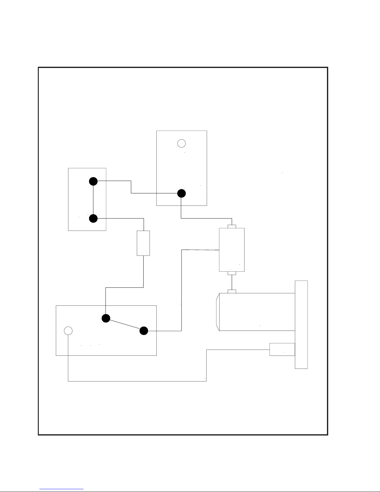
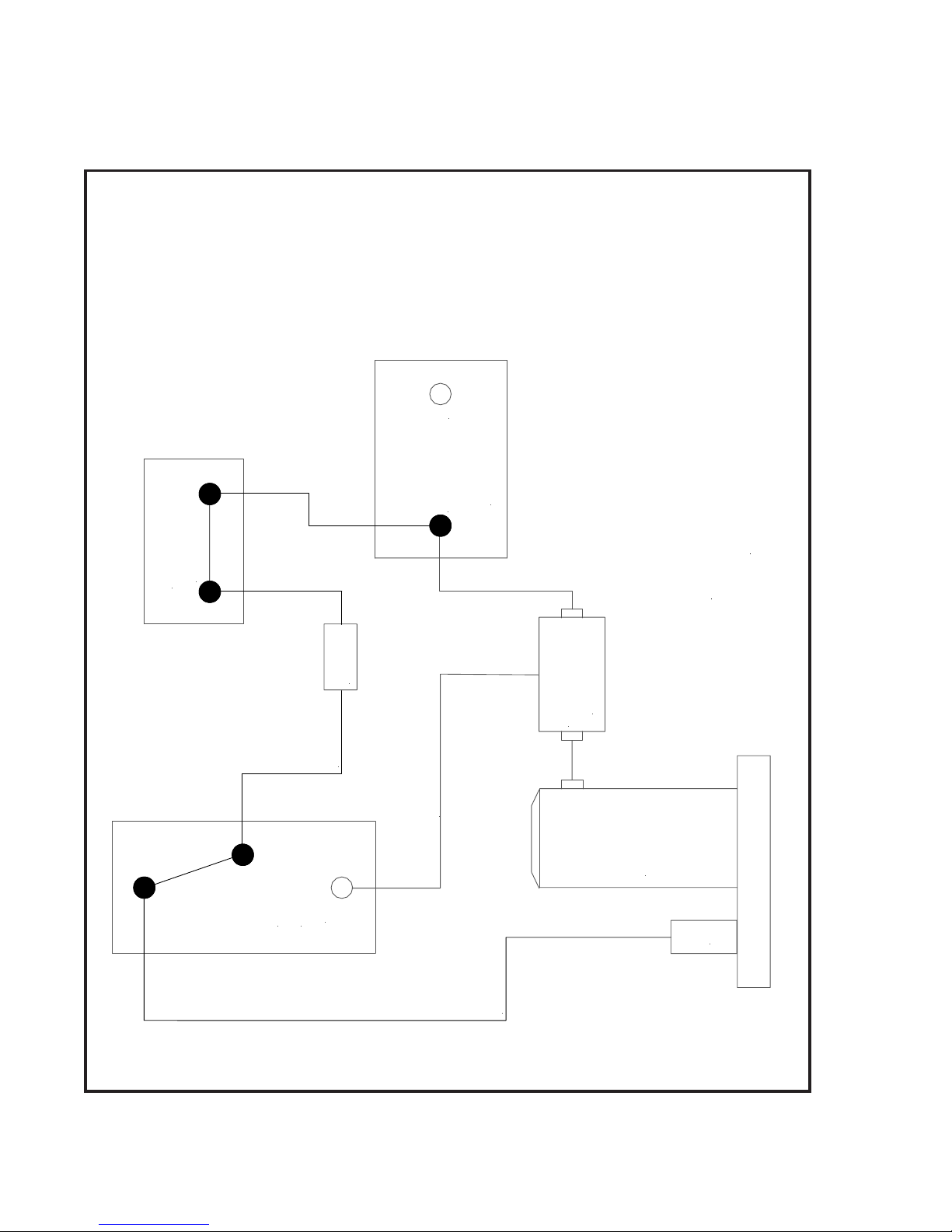
-
RAISE
SWITCH
IGNITION
LOWER
SWITCH
RAISE &
FUSE
BLACK
WHITE
+
BATTERY
SOLENOID
FIGURE 1-1A
SWITCH
MOTOR
A
BLACK
-6-
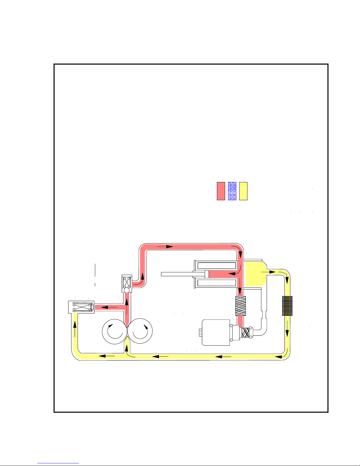
- OPE R ATING
- RETURN
- INTAKE or DRAIN
RAISE
HYDRAULIC FLOW CHART
MODELS E-46 & E-46H
TANK
PRESSURE
RE L IEF
E-46 & E-46H
1650 + 50 P.S.I.
CHECK VALVE
LIFT
CYLINDER
FILTER
STRAINER
FIGURE 1-1B
"A"
-7-
SOLENOID
SWITCH
IGNITION
FUSE
BLACK
-
+
WHITE
BATTERY
FIGURE 1-2A
LOWER/FLOAT
SWITCH
SOLENOID
SWITCH
RAISE &
MOTOR
LOWER
A
BLACK
-8-
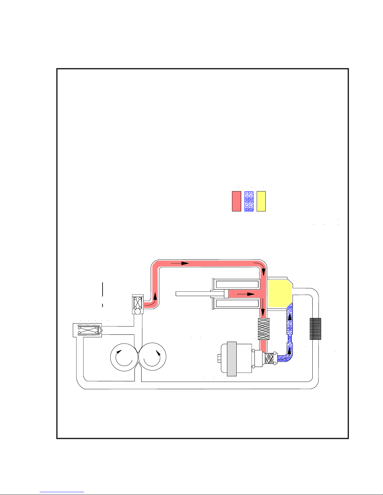
- OPERATING
- RET U RN
- INTAKE or DRAIN
HYDRAULIC FLOW CHART
LOW ER/FLOA T
MOD ELS E-46 & E-46H
TANK
PRESSURE
RE L IEF
E-46 & E-46H
1650 + 50 P.S.I.
CHECK VALVE
LIFT
CYLINDER
"A"
SOLENOID
ENERGIZED
FILTER
STRAINER
FIGURE 1-2B
-9-
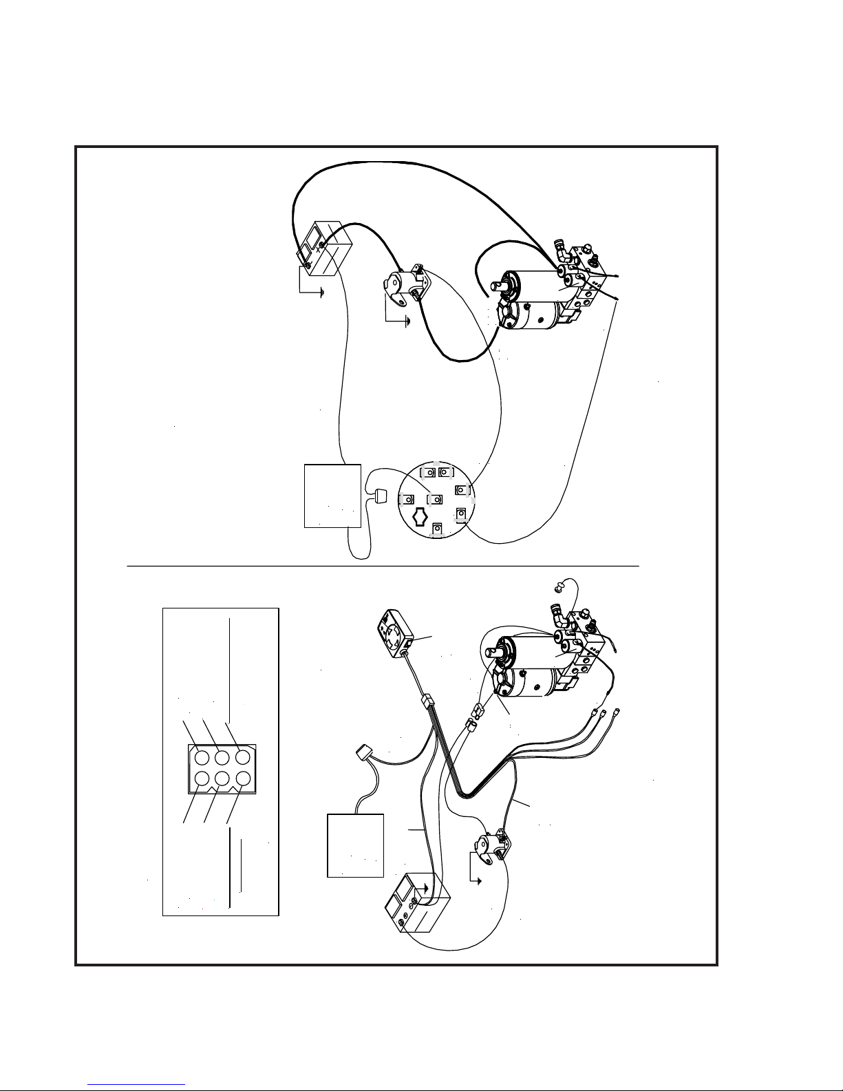
SL IK - STIKSINGLE LEVER
CONTROLLER
GROUND
(BLUE WIRE)
(ORANGE WIRE)
POWER TO SWITCH
6
3
ELECTRO -TO UCH
CONT R OLLE R
(BLACK WIRE)
(GREEN WIRE)
TO "A" SOLENOID
TO "C" SOLENOID
(WHITE WIRE)
TO MOTOR SOLENOID
4
5
2
1
(RED WIRE)
TO "B" SOLENOID
"B"
N
N
I
I
A
A
R
R
D
D
RAISE
Ignition Switch
RAISE
D1NEGATIVE
A2POSITVE
WHITE WIRE - ENERGIZED
Moto r Solenoid
L
E
E
S
N
U
"ON"
F
10
A
P
H
C
T
I
W
E
S
R
I
O
W
T
E
R
U
E
L
B
W
O
1
0
A
P
GENUINE PARTS
C - H
C - H
Meyer
Meyer
F
H
F
C
O
T
/
I
N
W
S
O
E
V
I
1
T
D
A
G
E
N
2
A
"
B
"
E
V
T
I
S
O
P
.
D
E
Z
I
G
R
E
N
E
s
i
d
i
o
en
l
o
S
"
B
"
e
r
i
w
d
e
R
N
N
I
I
A
A
R
R
D
D
D
E
R
FIGURE 1-3A
FIGURE 1-3A
D
E
N
R
I
U
W
O
R
E
G
L
G
E
END OF TOUCH PAD HARNESS
E
N
H
S
N
A
C
U
A
"ON"
Ignition S w itc h
R
T
F
I
P
O
W
S
G
E
N
Y
R
E
S
T
O
T
P
A
B
D
N
U
O
R
G
E
E
T
I
R
I
H
W
W
R
E
W
O
P
-10-
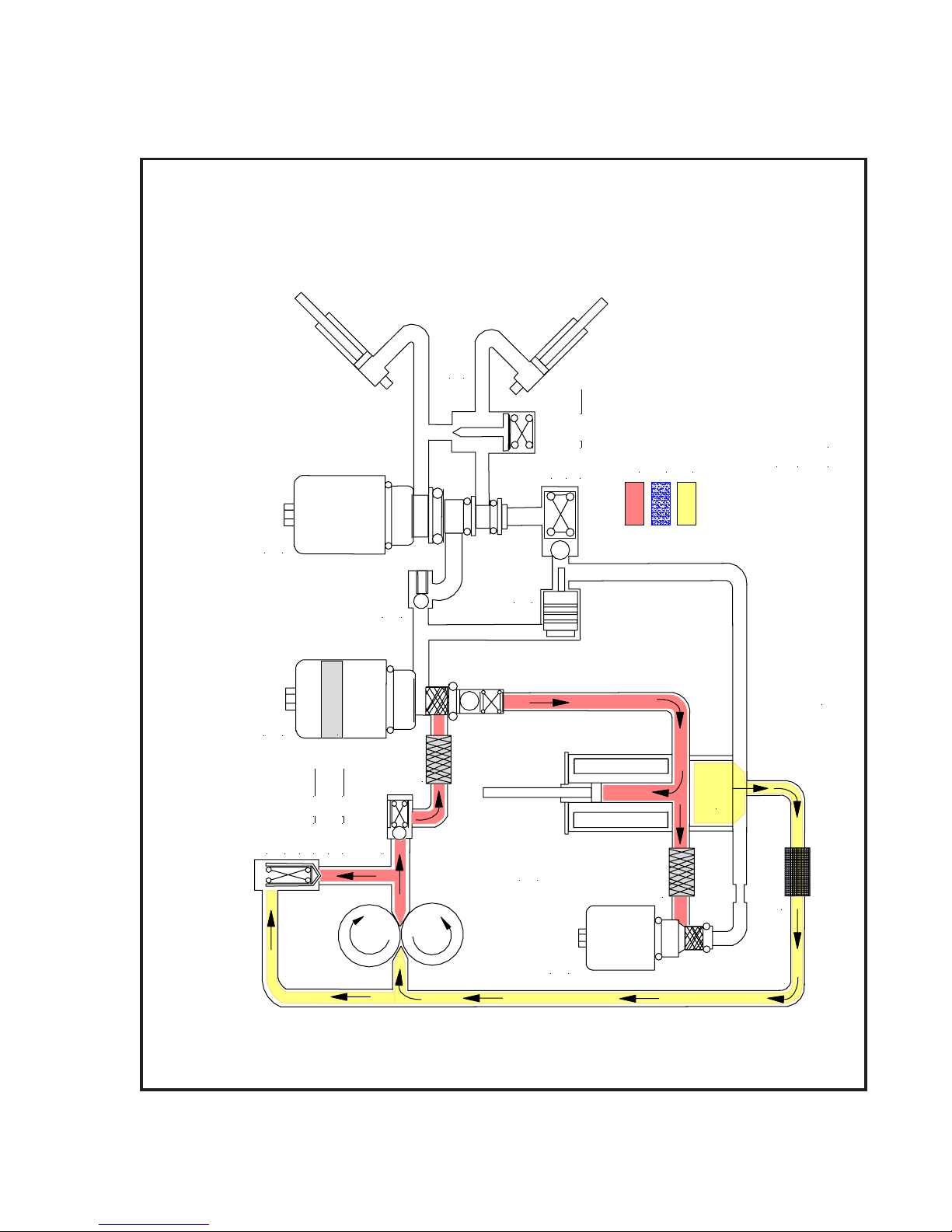
POWER ANGLING
CYLINDERS
RAISE
HYDRAULIC FLOW CHART
M ODELS E - 4 7 & E-57
- OPERATING
- RETURN
CROSSOVER
REL IEF
3800 + 400 P.S. I
"C"
SOLENOID
PILOT
CHECK
VALVE
CHECK
- INTAKE or DRAIN
FIGURE 1-3B
"B"
SOLENOID
ENERGIZED
FILTER
TANK
PRESSURE
RELIEF
E-47
1650 + 50 P.S. I.
E-57
2000 + 0 P.S. I.
CHECK VAL VE
LIFT
CYLINDER
FILTER
STRAINER
"A"
SOLENOID
-11-
S
S
TIK
LIK -
SINGLE LEVER
CONTROLLER
LOWE R/FLOA T
d
i
o
n
e
l
o
S
"
A
"
e
r
i
w
k
c
a
l
B
.
D
E
Z
I
G
R
E
N
E
s
i
d
i
o
n
e
l
o
S
"
A
"
e
r
i
w
10
"ON"
Ignition Sw itc h
GENUINE PARTS
C - H
C - H
Meyer
Meyer
k
c
a
l
B
FIGURE 1-4A
ELECTRO -TOUCH
CONTROLLER
GROUND
(BLUE WIRE)
(ORANGE WIRE)
POWER TO SWITCH
TO MOTOR SOLENOID
5
6
2
3
(BLACK WIRE)
(GREEN WIRE)
TO "A" SOLENOID
TO "B" SOLENOID
TO "C" SOLENOID
E
V
I
1
T
D
A
G
E
E
N
V
T
2
F
H
F
C
O
T
/
I
W
N
S
H
C
T
(WHITE WIRE)
LOWE R/FLOA T
4
I
W
S
TO
R
E
W
O
1
0
A
P
O
E
R
I
W
E
U
L
B
I
A
S
O
P
d
i
o
n
e
l
o
S
"
A
"
e
r
i
W
k
c
a
l
B
K
C
A
L
B
1
D
E
N
R
I
U
W
O
END OF TOUCH PAD HARNESS
"ON"
(RED WIRE)
Ignition Switch
R
E
G
L
G
E
E
N
H
S
N
A
C
U
A
R
T
F
I
P
O
W
S
G
E
N
Y
R
E
T
S
O
T
P
A
B
D
N
U
O
R
G
E
E
T
I
R
I
H
W
W
R
E
W
O
P
FIGURE 1-4A
-12-

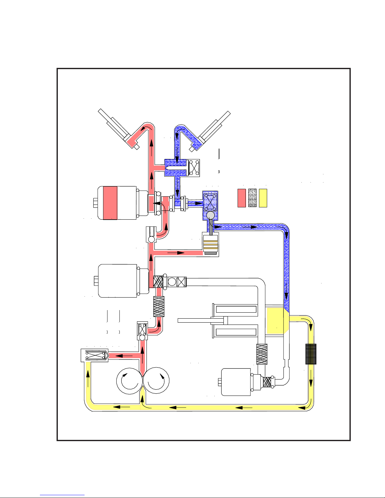
POWER ANGLING
CYLINDERS
- OPERATING
- RETURN
CROSSOVER
RE LIEF
3800 + 400 P.S.I
"C"
SOLENOID
PILOT
CHECK
VALVE
CHECK
- INTAKE o r DRAIN
HYDRAULIC FLOW CHART
LOW ER/FLOA T
MODELS E-4 7 & E-57
FIGURE 1-4B
"B"
SOLENOID
FILTER
TANK
PRESSURE
RELIEF
E-4 7
1650 + 50 P.S.I.
E-5 7
2000 + 0 P.S.I.
CHECK V ALVE
LIF T
CYLINDER
FILTER
STRAINER
-13-
"A"
SOLENOID
ENERGIZED

SLIK - S T IKSINGLE LEVER
ELECTRO -TOUCH
CONT R OLLER
CONTROLLER
GROUND
(ORANGE WIRE)
(BLACK WIRE)
TO "A" SOLENOID
(BLUE WIRE)
(WHITE WIRE)
POWER TO SWITCH
TO MOTOR SOLENOID
5
6
2
3
(RED WIRE)
(GREEN WIRE)
TO "B" SOLENOID
TO "C" SOLENOID
"C"
N
N
I
I
A
A
R
R
D
D
D1NEGATIVE
A2POSITVE
e
r
i
w
n
RIGHT ANGLE
L
E
E
S
N
U
A
"ON"
F
P
Ignition Switch
RIGHT ANGLE
4
1
0
A
H
TC
I
WHITE WIRE - ENERGIZED
Motor Solenoid
10
W
E
S
R
I
O
W
T
E
R
U
E
L
B
W
O
P
GENUINE PARTS
C - H
C - H
Meyer
Meyer
F
H
F
O
TC
/
I
W
N
S
O
E
V
I
1
T
D
A
G
E
N
E
V
T
2
I
A
S
O
P
e
e
r
G
"
B
"
N
N
I
I
A
A
R
R
D
D
1
D
E
N
R
I
U
W
O
R
E
G
L
G
END OF TOUCH PAD HARNESS
E
E
N
H
S
N
A
U
A
"ON"
Ignition Switch
R
TC
F
I
P
O
W
S
G
E
N
Y
R
E
T
S
O
T
P
A
B
D
N
U
O
R
G
E
E
T
I
R
I
H
W
W
R
E
W
O
P
.
D
E
Z
I
G
R
E
N
E
s
i
d
i
o
n
e
l
o
S
"
C
"
FIGURE 1-5A
N
E
E
R
G
FIGURE 1-5A
-14-
POWER ANGLING
CYLINDERS
HYDRAULIC FLOW CHART
MODELS E-47 & E-57
- OPE R ATING
- RETURN
CROSSOVER
RELIEF
3800 + 400 P.S.I
"C"
SOLENOID
ENERGIZED
PILOT
CHECK
CHECK
VALVE
- INTAKE o r D R A IN
ANGLE RIGHT
FIGURE 1-5B
"B"
SOLENOID
NOT
ENERGIZED
FILTER
TANK
PRESSURE
RELIEF
E-4 7
1650 + 50 P.S.I.
E-5 7
2000 + 0 P.S.I.
CHECK VALVE
LIFT
CYLINDER
FILTER
STRAINER
"A"
SOLENOID
-15-
 Loading...