

Page 1
PARTS & INSTALLATION INSTRUCTIONS
E-58H ELECTRO- LIFT
®
with ELECTRO-TOUCH and 1-1/2" x 10" P.A. Rams
Parts List
Item Part No. Qty. Description
15988 1 Lift and P.A. Ass'y. (Complete) 12 volt
1 15995 1 • Lift Ass'y. (Unit only) 12 volt
2 15630 1 • E-58H Lift Unit Cover
3 15631 1 • Cover Strap
4 15370 1 • Starter Solenoid - 12 volt
07620 2 • Ram L.H. & R.H. with Hose & Fittings
5 07968 1 •• Ram (1-1/2” x 10”)
6 22461 1 •• Hose Ass'y. SAE 1/4 x 38" Lg. M-6 Faceseal
7 22460 1 •• SAE 6 x 90 Degree Elbow
8 22691 1 • Universal Truck Side Harness
9 22692 1 • Plow Side Harness
10 05024 1 • Power Cable - 36"
11 08473 1 • Relief Valve Kit - Reservoir
15787 1 • Hardware Bag
07273 1 •• Tap Connector
12 21398 2 •• S. Tapping Screw 1/4 - 14 x 3/4"
13 21832 1 •• Bushing - Split
21953 1 •• Decal - Danger (Mount on Dashboard)
14 22690 1 • Pistol Grip Controller
08364 1 • Hardware Bag (P.A. Rams)
15 20146 2 •• Bolt H 5/8 - 11 x 3 1/4" Gr. 5
15 20150 2 •• Bolt H 5/8 - 11 x 4 1/2" Gr. 5
16 20309 4 •• Locknut 5/8 - 11
08202 1 • Plug Bracket Kit
17 19607 1 •• Plug Bracket
18 19609 1 •• Plate
19 20027 2 •• Bolt H 5/16-18 x 1 Gr. 2
20 22658 2 •• Bolt H 5/16-18 x 3 Gr. 2
21 20525 4 •• Finish Nut 5/16-18
22 20326 4 •• Lockwasher 5/16
* 08206 1 Complete Coupler Kit *Optional
23 22442 1 • Male P.A. Block Coupler
24 22443 1 • Female Hose Coupler
25 22444 1 • Male Hose Coupler
Parts indented are included in the carton, bag or assembly under which they are indented.
26 22445 1 • Female P.A. Block Coupler
Form No. 1-841R6
August 2008
Meyer Products LLC reserves the right, under its continuing product improvement program, to change construction or design details,
specifications and prices without notice or without incurring any obligation.
Meyer Products LLC
18513 Euclid Ave. • Cleveland, Ohio 44112-1084
Phone 486-1313 (Area Code 216)
www.meyerproducts.com• email info@meyerproducts.com
© 2008 Printed in the U.S.A.
6 Angell Lane • Damariscotta, ME 04543-4507
Meyer Products LLC
Phone 563-2227(Area Code 207)
www.meyerproducts.com• email info@meyerproducts.com
Page 2
GENERAL INFORMATION:
CAUTION: Always disconnect battery prior to
installation.
Check contents against the parts list to determine
all are correct and included. When ordering parts,
furnish Part No., Name and Description, Type of
Hydraulic Unit and Moldboard Size.
SAFETY PRECAUTIONS should be used when
Electro- Lift
RAISED position. LOWER plow to ground when
vehicle is PARKED.
OVERHAUL and SERVICE INFORMATION is
covered on separate instructions.
For Electro-Lift® Unit maintenance, refer to
"Owner's Manual."
NOTES:
1. Connect ground cable to negative side of battery for a solid
connection to ground.
2. Caution: Route all cables away from moving engine parts,
Manifolds, and sharp sheet metal.
3. For weather protection, tape all electrical connections at front
of vehicle.
4. The vehicle must be equipped with a "Heavy Duty Battery" (70
Amp. Hr. Min.) 550 C.C.A. and "Alternator" (60 amp. Min.) to
obtain maximum performance.
5. Follow these instructions explicitly. Warranty does not apply
to a Meyer product which has been negligently or improperly
assembled or installed.
®
is in OPERATION and plow is in a
INSTALLATION INSTRUCTIONS
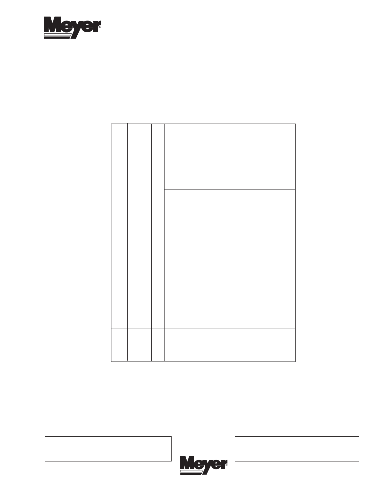
A. Remove shipping plug from filler hole and install Relief
Valve Kit (11). Tighten to 100-125 in. lbs.
B. Attach Plow Side Harness (9) power cables to the
Hydraulic Lift Unit (1). Attach the red (+) cable to the
motor stud marked (A2). Attach the black (-) cable to
the motor stud marked (D1). Connect the red, black
and green wires from Plow Side Harness (9) and connect
to solenoids on the Power Angling Block. See Figure 2.
To Motor S t u d
Positve - A2
G
B
L
A
C
K
"
A
R
E
D
"
B
"
R
E
E
N
"
C
"
"
Ground Connection
Motor Stud "D1"
BLACK
To Passenger Side
Plow Light
Drivers Side
Plow Light
2
RED
Rear View
FIGURE 2
4
12
"A"
Light
Adapter
Red
10
White
G
E
N
S
O
P
Y
R
E
T
T
A
B
"B" Harness
Power/Ground
Park &Turn
22
21
8
19
8
13
Black
Black Ground
"C" Harness
To P l o w L i g ht
Orange to "B"
harness of light modules
FIGURE 1
22
17
21
"A"
20
14
"B"
Not Used
"C"
Blue
18
"B"
Red Wire
(Raise)
"A"
Black Wire
(Lower/Float)
Drop
Adjustment
25
P.S. Ram
(Left Angle)
26
"C"
Green Wire
(Right Angle)
D.S. R a m
(Right Angle)
23
24
2
3
9
11
1
6
7
5
15
6
7
16
5
Page 3

INSTALLATION INSTRUCTIONS CONT.
C. Install E-58H Lift Assembly (1) to Lift Frame (using bolts
supplied in the mounting carton), with the Electric Motor
toward the right hand side (Passenger side); attach
the lift ram to the Lift Arm. When installing on E-Z Mount
Classic, reference SB 208.
WARNING:
Lift arm extends beyond bumper of vehicle. To minimize
damage from a front-end collision, lift arm should be
removed from vehicle when snow plow is not in use.
D. Install Universal Truck Side Harness (8) through the
vehicle grill.
H. Use Bushing (13) where Harness (8) is routed through
firewall and radiator support panel. Requires 7/8"
diameter hole. Be certain to route all wiring around hot
or moving engine parts, and any sharp sheet metal.
Protection must be provided to guard against wire
damage at these points. All excess or loose wire must
be neatly secured using wire ties. Fused lead from
Wiring Harness (8) must be attached to terminal in fuse
panel that is activated only when the ignition key is "on."
I. Install Starter Solenoid (4) to metal surface in engine
compartment using Screws (12). (Solenoid must be
grounded to operate). Attach Red Power Cable (8) to
a large terminal on Starter Solenoid (2). Attach Black
Ground Cable (8) to negative (-) terminal of battery.
Attach 36" Power Cable (10) to positive (+) terminal of
battery and remaining large terminal on Starter
Solenoid (2). Attach small white wire from harness (8)
to small terminal marked (S) and small black wire from
harness to small terminal marked (I)(Ground) on Starter
Solenoid (8).
M. Attach orange wire from harness (8) to the orange wires
from each light module. This will eliminate the need for
an additional switch in the cab to operate the snow plow
lights. When the Pistol Grip Controller (14) is turned on
the plow lights will be activated and when the controller
(8) is turned off the plow lights will be deactivated.
Note: All electrical connections should have both ends
coated with a dielectric grease prior to final installation.
This will ensure a good connection and help in
preventing corrosion.
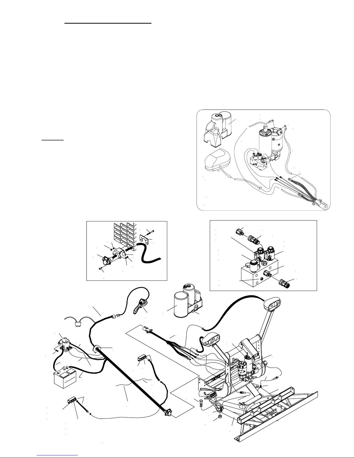
POWER ANGLING CYLINDERS:
Attach Meyer Power Angling Cylinders (5) to Sector and
A-Frame using bolts (15) and locknuts ( 16).
Note: 5/8-11 x 4-1/2” Bolts (15) must be used to
connect the angle cylinder to the LP & DP Pivot Bar.
Make certain Ram (5) on Driver's side connects to the
Drivers side port on the P.A. Block (SEE FIGURE 1).
Optional Couplers Note: When installing plow system to
a E-Z Mount Classic or Custom Mountings optional coupler
kit 08206 must be purchased seperately. These couplers
will install between the P.A. Block and the hoses. When the
Moldboard Assembly is removed from the vehicle, to
prevent contamination to the Couplers and Hydraulic
system, the L.H. and R.H. Power Angling Hoses must be
reattached by plugging the couplers together.
Power Angling Cylinders furnished with the Electro-Lift
have been factory filled with the proper amount of fluid. If
for any reason it is necessary to add fluid to Reservoir or to
bleed the Power Angling Cylinders, proceed as follows:
A. Remove Relief Valve (11) from Reservoir to add fluid
during charging and bleeding.
B. Temporarily loosen both hose connections at the R.H.,
L.H. Power Angling Cylinders. Base end of Cylinder
must be higher than Rod end to enable trapped air to
escape.
C. Angle the Plow in both directions until fluid leaks out at
both points in a steady flow.
D. Retighten the hose connections.
NOTE:
Proper fluid level is 1-1/2" below filler hole. It must be
checked with the lift arm fully retracted (down).
For snow plow light installation see separate
instructions.
Reference Form 1-757 see Paragraph 7
Route Cables “C” (Yellow) from module to Male Plug (8).
Connect both “C” Harness female ends to the male
corresponding ends of the Male Plug (8). As per Figure 1.
Connect both male ends from the snow plow light to the
female ends on the Female Socket (9). As per Figure 2.
Check snow plow light blinkers to make sure the wires have
not been reversed.
Meyer Products LLC assumes no responsibility for
installations not made in accordance with these
instructions.
®
 Loading...