

Page 1
1-634
May , 2003
DIAGNOSTIC FLOW CHART FOR
E-46, E-47 and E-57 ELECTRO LIFT
These charts are intended to be used as an aid in diagnosing problems on the Electro Lift® units. They are not a substitute for
factory training and experience. Be certain to read the General Information and Testing Tips sections before attempting any troubleshooting.
General Information
Before any troubleshooting is started, make certain the following conditions are met.
1. The moldboard is pointing straight ahead. This can often be done by coupling the left cylinder into the right cylinder and
pushing the moldboard by hand.
2. The power angling cylinders must be installed correctly on to the A- frame. The left cylinder (Driver’s side) has a hose
attached with a male half of a coupler at the end; the right cylinder (Passenger side) has a hose attached with a female half
of a coupler at the end.
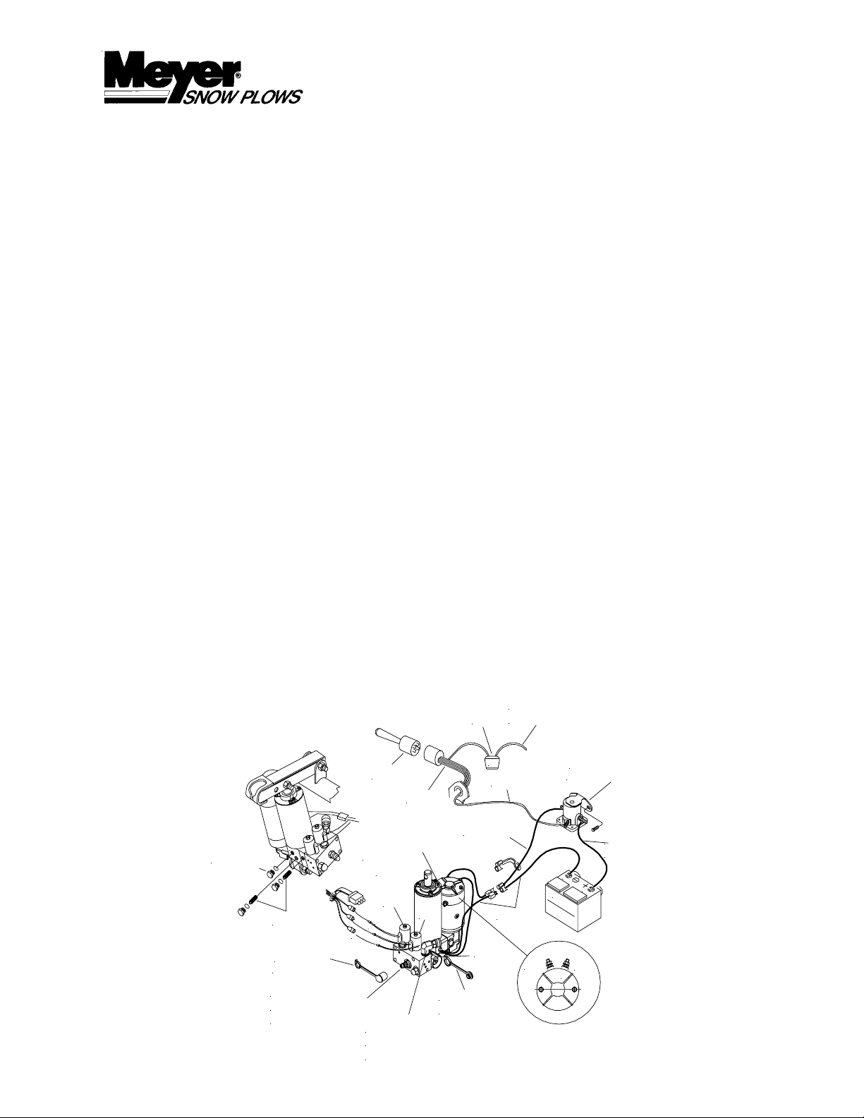
3. The solenoid coils must be on their proper valve. The “C” coil (green wire) must be next to angling fittings. The “B” coil
(red wire) is located to the front of the Electro Lift® Unit. The “A” coil (black wire) is smaller and is located on the back side
of the unit. (See Drawing).
TESTING TIPS
®
UNITS
Many tests do not require removing the Electro Lift® unit from the vehicle. However, more thorough testing can be performed
using the Meyer Test Stand which allows direct pressure and amperage readings.
1. Using a screwdriver or other small tool to check for magnetism of the solenoid coils “A”, “B”, “C”. Place the tool on the nut
securing the coil and have an assistant operate the switch. You should feel strong magnetic attraction.
2. Use a test light or volt meter to determine whether there is power at the harness or switch.
3. When determining AMP draw of the motor, always obtain the highest value possible, i.e, at maximum raise or maximum
angle with motor running.
4. Proper rotation for the 3” motor (American Bosch) is indicated by an arrow located on top side of the (Part # 15026) pump.
5. The pump shaft of a good pump can be turned smoothly using two fingers. If it can’t be turn easily, the pump is too tight
and must be replaced.
6. Pump pressure can be measured at an angle hose (note pressure at full angle) or in the pressure filter port (an adaptor is
necessary for the filter port). Note: The E-57 Electro Lift® Unit has a non adjustable pressure relief valve.
7. Flush the complete system including unit, hoses and power angling rams with a non wax (Napthenic) cleaner. If kerosene
(Parrafinic) is used to flush the system, the system must be flushed again to remove any kerosene with a (Napthenic)
based cleaner that is wax free.
To Ignition Switch
(Accessory Side)
FUSE
22092
20A
White
Motor Solenoid
(Must be grounded)
15680
D
R
A
I
D
A
R
I
N
P
N
L
U
G
F
L
I
E
T
Coupler
Weather Cap
R
S
To Passenger Side
Power Angling Ram.
(Angle Left)
Pressure Relief
Filler Plug
"B"
G
R
E
R
E
E
N
D
"
"
B
C
"
"
B
L
A
C
K
"
A
"
To Driver's Side
"C"
Coupler
Weather Plug
"A"
Ground
A2
B
A
T
T
+
-
To Motor
N
E
G
P
O
S
E
R
Y
D1
To Positive
Battery Terminal
Power Angling Ram.
(Angle Right)
Page 2
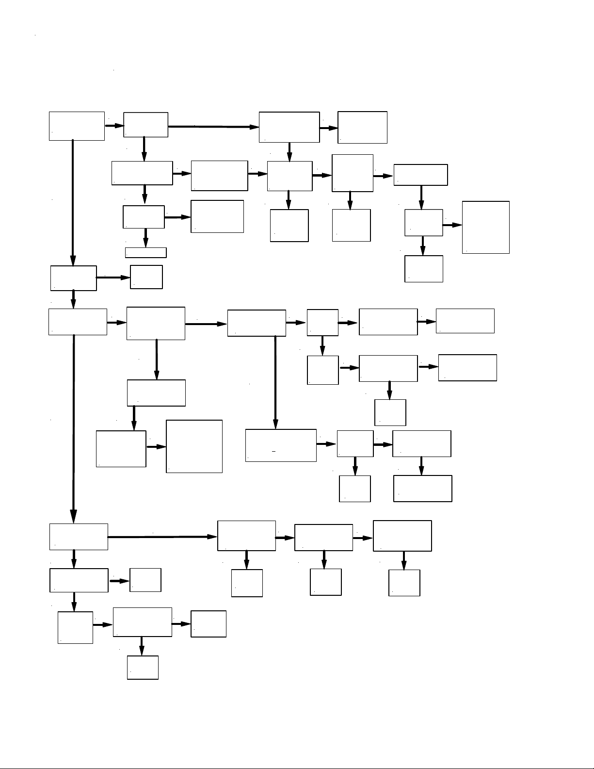
SNOW PLOW WILL NOT RAISE
Does the
Motor Operate?
YES
Is the fluid level
1-1/2" below
filler hole?
YES
Does the snow plow
angle to the left
instead of raising?
YES
NO
Is there power
going to
the mo to r ?
YES
Remo v e motor.
Does motor run when
12 volts is applied?
YES
Can the pump
shaft turn b y
hand?
YES
Replace pump.
NO
ADD M-1
Fluid
Does the snow plow
NO
angle when the
An g le Switch
is activa te d ?
YES
Clean or Replace
"A" Valve.
-Retes t Does snow plow
raise?
NO
YES
Is the "A" Valve
stuck in the
open position?
Disassemble unit Inspect O-rings,
NO
Cylinder,Piston
assem bly.
Look for blockage in
Sump Casting
passages.
NO
Inspec t Motor -
NO
Armature, Brushes
Repair or Replace
Motor as necessary
Is Ground Cable
attached to the
Negative (-)
Battery Termina l?
NO
Are all electrical
connections clean
and tight?
Is Battery Charged?
YES
Is there power
NO
going to the
motor solenoid,
at White Wire?
YES YES
Replace the
Motor
Solenoid.
Is there pressure
(or flow) a t the
Filter port?
YES
Can pump relief pressure
be adju s te d to
50 P.S.I
1650 +
E-46 & E-47
Charge Battery -
NO
Clean and tighten
all electrical
Connections.
Is there power
leaving the
NO
switch?
Check switch
for Cont inuity
Replace the
Wiring
Harness.
Are the
NO NO
Filters
Clogged?
YES
Clean
or
Replace
Filters.
NO
NO
Is the pump
shaft turn ing
tightly?
YES
NO
Is the m o to r tu rn in g
the proper direction?
Check for clogged
strainer - Is oil getting
to the pu mp?
YES
NO
Replace
the
Pump.
Check Wires at
Molded connector.
YES
YES
Replace
the
Pump.
YES
Repair or Replace
the m ot o r.
Is the Fu s e
OK?
Replace the
Raise
Switch .
NO
NO
Does the motor
armatu re turn
tightly?
Replace Fuse.
Check fo r s h o r t
NO
in Harn e s s ,
"B" Coil, Sw itch
Connections,
Motor Solenoid,
Electric M otor.
Check B ru s hes for
proper installation or
replace motor.
Clean s tra in e r
and flush the
system completely.
Does th e "B" Coil
(Red Wire) have
magnetism?
YES
Are the "B" Valve
O-Rings in good
Condition?
YES
Clean or
Replace the
"B" Valve
and retest.
NO
Replace P.A. Block
NO
with E-46 plate and
retest. - D o e s s n o w
plow Raise now?
YES
Replace
O-Rings.
Replace
P.A. Bl o ck
NO
NO
Replace
Sump Base.
Is there power to
the "B" Coil?
(Red Wire)
at Harness
YES
Replace
"B" Coil.
NO
Is there power
leaving the switch
at the red wire?
YES
Replace
the wiring
harness.
NO
Are wires in
molded connector
making contact
with the switch?
YES
Replace
the Raise
switch.
Page 3

SNOW PLOW LEAKS DOW N
Does the
NO
snow plow drop
straight down?
YES
Are "A" Valve O-rings
in good co n d itio n ?
Does "A" V alve stem
move freely?
YES
E-47: Dissasemble unit
Inspect O-Rings,Cylinder,
Piston Assembly.
Does it hold now?
NO
NO
Does the snow plow
drop and angle
to the left?
YES
Replace
"B" Chec k Valve
Does it now hold?
Replace O-Rings
Replace "A" Valve
"E-46 ONL Y "
Replace Pump Check Valve
(Remember to coin the ball to the seat).
Does it now Hold?
NO
Replace
Sump Base
NO
Replace
"B" V a lve
Does it now hold?
NO
NO
Dissasemble unit
Inspect O-R ing s,C ylin de r,
Piston As se m b ly.
Does it hold now ?
Replace
Sump Base
NO
Replace
Sump Base
Does "A" Coil
(Black Wire) have
magnetism?
YES
Replace "A" V alve
Does it now lower?
SNO W PLO W WILL N O T LO WER
NO
Is there pow er to the
"A" Co il (B la c k Wire)
at harness?
NO
Check for a clogged
filter or a blocked
passageway .
YES
Replace
"A" Coil
NO
Is there power leaving
the switch at the
Black Wire?
YES
NO
Check for Bent or
Siezed Ram
Assem b ly.
Replace
Harness
NO
Are wires in molded
connector making contact
with the switch?
YES
YES
Replace
Switch
Is Fuse
OK?
NO
Replace the fuse Check for short in
harness, "A " Coil,
Switch connections.
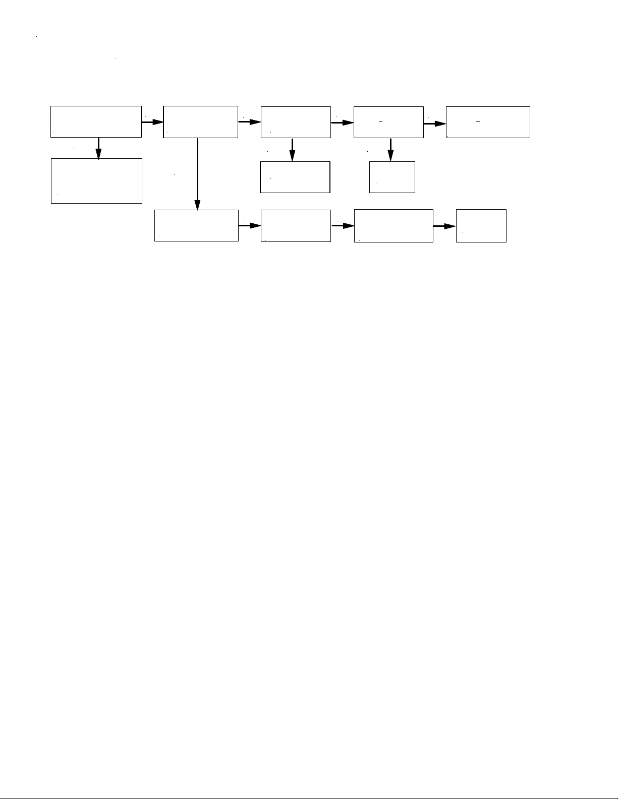
Page 4

Can the snow plow
Raise?
YES
Does the motor run
when angle switch
is pushed?
SNOW PLOW WILL NO T A NG LE LEFT
See the Raise
NO
Flow Chart
Section
NO
Is there power to
the motor solenoid?
(White Wire)
NO
Is there power
leaving the switch?
YES
NO
Are the wires in
molded connector
making contact with
the switch?
YES
YES
Does the snow plow
raise instead of
angling left?
YES
Clean or replace the
"B" Valve.
Retest
Does the snow plow
NO
angle to the right when
the angle switch is
pushed left?
YES
Clean or replace the
"C" Valve.
Retest
Replace Harness
Is the ampere draw
NO
less than 100 amperes
while trying to angle
snow plow?
YES
Is the P il o t p is to n i n
NO
good condition?
(worn/sloppy or Missing)
YES
Are "C" Valve
O-Rings in good
condition?
YES
Clean or replace
the Crossover Relief.
Does the snow plow
now angle?
NO
NO
NO
NO
Replace
Piston
Replace
O-Rings
Replace the
P.A. Bl ock
Replace Angle
Switch
Can the snow plow be
angled by hand when
the P.A. Rams are
disconnected from A-Frame?
YES
Will the snow plow angle
right & le ft if n o t a llo wed
to travel to extreme
angled position?
YES
T emporarily put 1/2" blocks
between the Sector and
A-Frame to limit the degree
of angle. Will the snow plow
now angle?
Weld
1-1/2" x 1-1/2" x 1/2"
spacers to the A-Frame
stops.
YES
Relieve the interference
NO
between the
Sector and A-Frame.
NO
Does pressure remain
in angle hose when the
motor is not running?
YES
If both hoses are stiff
inspect the Pilot Check
Piston and "C" Valve
for binding.
Replace both the
NO
Coupler sets and/or
clean or replace the
"C" Valve.
If one hose is stiff
inspect the the "C"
valve for binding.
Replace Coupler sets.
Page 5

SNOW PLOW W ILL NOT ANGLE RIGHT
Can the snow plow
Rais e ?
YES
Does the motor run
when angle switch
is pushed?
YES
Does the snow plow
raise instead of
angling left?
YES
Clean or replace the
"B" Valve.
Retest
NO
NO
Is there p o wer to
the motor solenoid?
(Wh ite Wire)
NO
Can the snow plow
angle to the Left?
Does the "C" Coil
have magnetism?
(Green Wire)
See the Raise
Flow Chart
Sectio n
YES
YES
NO
Is there power
leaving the switch?
YES
Replace Harness
Is there power to
NO
the "C" Coil?
(Green wire at harness)
YES
Replace the
"C" Coil.
Rete st
NO
NO
Are the wires in
molded connector
making contact with
the switch?
YES
Replace Angle
Switc h
Is there power
leaving the switch?
YES
Replace Harness
NO
Are the wires in
molded connector
making contact with
the switch?
YES
Replace Angle
Switch
Are "C" Valve
O-Rings in good
condition?
YES
Clean or replace
the Crossover Relief.
Does the snow plow
now angle?
NO
Replace
O-Rings
Replace both the
Coupler sets and/or
clean or replace the
"C" Valve.
NO
Replace the
P.A. Block
Page 6
SNOW PLO W W ILL NO T HO LD ANGLE
A r e the Rams mushy?
Can you push the moldboard
6" to 8 " by hand?
YES
Bleed air from the system
and snug up gland nuts.
Check couplers and fittings
for le a ks.
NO
Does the moldbo ard
hold le ft a ng le & re lea s e
from r ig ht angle?
YES
Inspe ct "C" Valve O -rin g s
Change if necess ary. Does
snow plow now angle?
Are the "C" Valve
NO
O-Rings in poor
condition?
YES
Replace O-Rings
Cha nge Pilot C heck
NO
Ball and Seat.
does snowplow
no w hold?
Is Crossover Relief set
NO
at 3800 +
Are Crossover O-Rings
in good conditio n ?
YES
Replace the
P.A. Block
Inspe ct Crossove r Relief.
NO
(Rebuild or Replace)
Does snow p low now
hol d angle?
400 P.S.I.?
Set Crossover Relief to
NO
380 0 +
Replace Crossov er O -R ings
or complete Crossover .
NO
400 P.S.I.
Replace the
P.A. Block
 Loading...