

Page 1
CP-10
Complementary
Phase
Parametric
Equalizer
Operating Instructions
The Meyer Sound CP-10 is a dual-channel para-
metric equalizer featuring five bands of fully
parametric equalization per channel with an
additional high and low shelving cut filter for
each channel. Any frequency between 60 Hz and
6 kHz can be controlled by two equalization cir-
cuits per channel. Frequencies below 60 Hz and
above 6 kHz are controlled by one equalization
circuit and one shelving cut filter per channel.
The front panel occupies 31/2 inches of rack space
and the clearly marked controls include individual
In/Out switches for each band of equalization.
There are separate, calibrated Center Frequency,
Bandwidth and Boost/Cut controls. The comple-
mentary phase circuitry assures controlled phase
distortion, even at extreme settings and the dy-
namic range of the instrument is better than 110
dB in operation.
The front panel can be removed without affecting
any equalization settings, and each of the four-
teen equalization circuits is mounted on its own
gold-socketed removable printed circuit board,
guaranteeing ease of service. LEDs indicate
power status and clip levels. Signal processing is
initiated by a relay that closes only when the
power supplies have stabilized. In the event of AC
failure, the unit automatically switches to
hardwire bypass.
Meyer Sound Laboratories, Inc.
2832 San Pablo Avenue
Berkeley, CA 94702
Page 2

CP-10
Complementary
Phase
Parametric
Equalizer
Operating Instructions
Connections
AC Power Inlet and
Voltage Selector Switch
Rear panel connectors are XLR-type and both inputs and
outputs are balanced. An associated rear-panel switch
labeled Balanced/Unbalanced Gain Adjust controls the
unit’s gain to accommodate either unbalanced or balanced
output connections.
In the Unbalanced position, unity gain is obtained using
single-ended output cables, and 6db of voltage gain is
added if balanced lines are used. Prior versions of the CP10 without this switch operate in this mode by default, and
cascading equalizer sections should be connected with the
CP-10 cascading jumper. In the Unbalanced position, the
channel gain is at unity when CP-10 is driving a singleended device input.
In the Balanced position, the unit will operate at unity gain
using standard balanced XLR cables (P3 -> P3, P2 -> P2,
P1 -> P1= shield), so that multiple CP-10 units can be
The rear-panel AC input connector is an IEC/CEE Standard Receptacle. The signal path relay closes only when
power supplies are stable and once the relay is closed the
unit is inserted into the signal path. In the event of loss of
AC power or unstable line voltage the CP-10 will automatically remove itself from the signal path into a hardwire
bypass mode. If the unit remains connected to the AC
supply it will automatically reinsert itself in the signal path
as soon as the power supplies stabilizes.
The rear-panel AC inlet is equipped with an integral
cascaded using mic cables, and the unit can be inserted in
an all-balanced system without affecting system gain.
Note that the labeling terminology for this switch refers to
the type of output connection cable required for unity-gain
performance; the switch affects only the gain of the unit. In
either position, the CP-10 input remains actively balanced
and its output remains push-pull.
In summary, if using unbalanced output cables, or if
compatibility with preceding versions of the CP-10 is
desired, set the switch in the Unbalanced position. If using
balanced output cables, put the switch in the Balanced
position.
A field installation retrofit is available to upgrade prior
versions of the CP-10.
voltage selector and a fuse holder, both concealed in a
compartment above the AC inlet. The selected voltage is
displayed in a small window and reads 115Vac or 230Vac.
In order to change the voltage, first disconnect the AC
cord. Open the door of the voltage-selector compartment
using a small screwdriver or pen-knife and remove the
voltage selector cam. Rotate the cam and replace it so that
the desired voltage is visible through the window of the
voltage selector compartment door. When the door to the
voltage selector compartment is closed and the AC cord is
reconnected, the unit is ready for use.
AC Fuse
Indicators
Ground Lift Switch
Front Panel Controls
In/Out Switch
The rear-panel voltage selector compartment contains a
1
/4 Amp SIo BIo 250 V fuse. In order to replace the fuse,
first disconnect the AC cord. Open the voltage selector
compartment (see the previous section) and remove the
sliding tray which contains the fuse. When replacing the
fuse tray, take care to insert it in the slot to the right, aligning the printed arrow with those on the inside door of the
voltage selector compartment. Close the compartment and
reconnect the AC cord. The unit is now ready for use.
The front panel of the CP-10 includes six LEDs. The two
Green LEDs indicate the power status at all times, the LED
marked Power indicating the presence of AC power and
the LED marked Ready indicating that the signal path
relay has engaged and that the selected equalization is in
circuit. The four Red LEDs indicate signal levels in excess
A ground Iift switch on the rear panel lifts pin 1 from the
chassis, which is grounded through the AC “U” ground.
This switch may be used to eliminate hum due to ground
Each of the ten tunable filter circuits has its own Center
Frequency, Bandwidth and Boost/Cut controls, and each of
The individual In/Out switches are provided so that individual filters may be switched in and out without changing
any settings. The efficacy of particular equalization settings
may thus be easily verified, both by measurement and
The fuse holder assembly can accommodate both U.S.and European-size fuses in their respective trays. When
the unit is shipped with the AC voltage set at 115, the U.S.
size fuse tray and fuse are included (Meyer Sound Part
Numbers 422.006 and 420.002, respectively). Otherwise
the European size fuse tray and fuse are supplied (Meyer
Sound Part Numbers 422.005 and 420.003, respectively),
and the voltage-selector cam is set at 230Vac.
of 16dBv at the input and output stages of the unit. If the
Input Clip LED for either channel is lit, reduce the level of
the input signal. If the Output Clip LED for either channel
is lit, reduce the amount of gain through the equalizer by
reducing the Boost setting in those equalizer sections that
are in use, or reduce the drive signal level.
loops. Pin 1 on the XLR connectors is tied to signal common at all times.
these filters can be inserted or removed from the signal
path with an individual In/Out switch.
subjective evaluation. In the Out position the signal is not
affected in any measurable way by any of the filter settings.
(For lowest system noise it is recommended that filters not
in use be bypassed using the In/Out switch.)
Meyer Sound Laboratories, Inc.
2832 San Pablo Avenue
Berkeley, CA 94702
Page 3
CP-10
Complementary
Phase
Parametric
Equalizer
Examples of
Complementary Phase
Equalization
Operating Instructions
Effective equalization of loudspeaker/room resonances requires exact and opposite matching with anti-resonance circuitry.
An example is shown here of the
correction of a response curve
aberration caused by reflection
from a single surface adjacent to
a loudspeaker under test (halfspace loading). All measurements
have been made with Meyer
Sound’s SIM® System II.
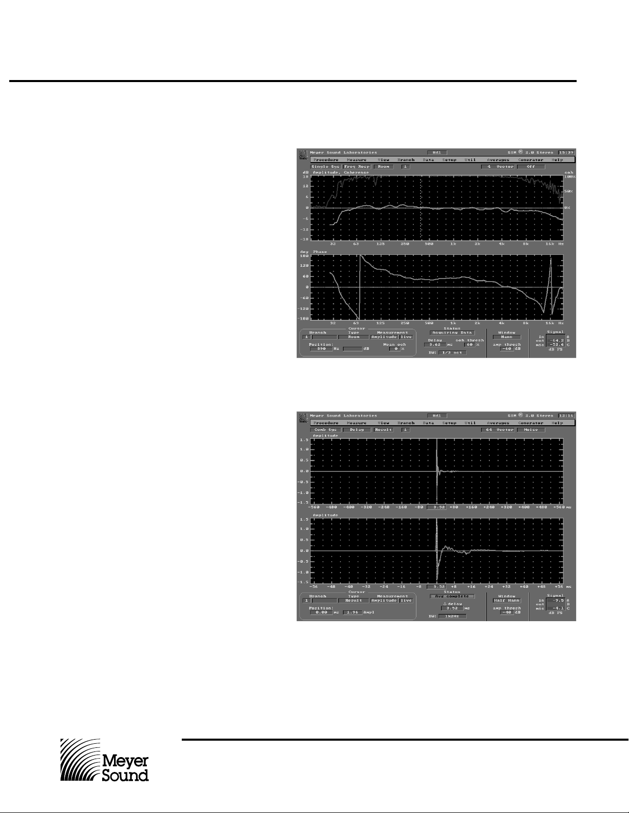
Figure 1
The test loudspeaker is first
measured in near-free space
conditions (on a stand approximately six feet off the ground,
away from all other reflecting
surfaces). The upper window
displays the amplitude response, and the lower the
phase response. Frequency
resolution is third-octave. The
loudspeaker exhibits very flat
response in both amplitude
and phase.
Figure 2
This display shows the impulse
response (amplitude vs time) of
the test loudspeaker under the
same near-free field conditions.
The upper window is a ±560
msec span, and the lower
window shows the same data
zoomed to a ±56 msec span.
The loudspeaker exhibits a
very controlled and coherent
impulse response.
Meyer Sound Laboratories, Inc.
2832 San Pablo Avenue
Berkeley, CA 94702
Page 4

CP-10
Complementary
Phase
Parametric
Equalizer
Operating Instructions
Figure 3
The loudspeaker is now placed
with its back against a wall,
again at approximately six feet
off the ground. This frequency
response measurement illustrates the low-frequency (below
500 Hz) aberrations that halfspace loading typically causes.
Disruptions appear in both the
amplitude and the phase trace.
Figure 4
This impulse response measurement of the loudspeaker in
half-space shows that the
frequency-response aberrations of Figure 3 also appear in
the time domain as echoes at
approximately 4 and 8 msec
(note peaks). These are reflections from adjacent surfaces.
Meyer Sound Laboratories, Inc.
2832 San Pablo Avenue
Berkeley, CA 94702
Page 5

CP-10
Complementary
Phase
Parametric
Equalizer
Operating Instructions
Figure 5
Complementary Phase Equalization is now applied to
remove the response aberrations shown in Figure 3. The
lower window shows the
unequalized loudspeaker
response (bright trace) with the
inverse of the equalizer response overlaid (grey trace).
The equalized loudspeaker
measurement (upper window)
shows restoration of the amplitude response.
Figure 6
This is the impulse response of
the corrected test loudspeaker
in half space. The echoes
shown in Figure 4 have been
suppressed, and the impulse
response restored. This is
proper deconvolution, as can
only be performed with
Complementary Phase equalization applied under highresolution measurement.
Meyer Sound Laboratories, Inc.
2832 San Pablo Avenue
Berkeley, CA 94702
Page 6

CP-10
Complementary
Phase
Parametric
Equalizer
Operating Instructions
Center Frequency
Control
Bandwidth Control
Boost/Cut Control
Each of the ten tunable filters in the CP-10 have a 10:1
frequency range and the Center Frequency Control
callibration is accurate to within 10%. Any frequency
between 20 Hz and 20 kHz may be selected for equalization and the overlap between filters is such that any frequency between 60 Hz and 6 kHz can be selected in two
filters per channel. This degree of versatility and precision
is most useful when equalizing resonances that are both
narrow in bandwidth and closely spaced in frequency.
Each of the tunable filters can be adjusted from a minimum
bandwidth setting of 0.1 octave to a maximum of 1.1 octaves. The Bandwidth Control is continuously variable
between these extremes and is accurately calibrated.
In combination with the Center Frequency and Boost/Cut
Controls, the Bandwidth Control makes it possible to
complement exactly a resonance or response peak in
order to remove the resonance and flatten system response.
The figure to the right shows a set of equalization
curves displaying symmetry at 10 dB boost and cut
(minimum and full bandwidth settings included)
The Boost/Cut Control for each of the tunable filters in the
CP-10 is continuously adjustable from 15 dB of boost to 15
dB of cut. In the center, or 0 position, the Boost/Cut Control
will have no appreciable effect on the signal unless an-
.
When two filters in the same channel are tuned to the
same frequency, the combined effect is dependent on the
amount of boost of cut selected in each filter and the
bandwidths chosen. When the same center frequency and
bandwidth are chosen, the net effect of the two filters will
be approximately two-thirds of the sum of the boost or cut
of the filters when inserted separately. If a filter is set to
0 dB of boost or cut, then it should be removed from the
signal path using the In/Out switch. This will prevent any
interaction with adjacent filters tuned to the same frequency.
Amplitude, 3dB per division
50 100 200 500 1k 2k 5k 10k 20k
Frequency in Hertz
other filter in the same channel is tuned to the same
frequency. In this case the amount of boost or cut available
in the active filter is reduced. It is recommended that filters
not in use be bypassed using the In/Out switch.
High and Low Shelving
Cut Filters
In addition to the tunable filters described above, there are
two shelving cut filters per channel, each with its own
control. The high and low shelving cut filters are so described because as each is turned from flat response to
maximum cut, the turnover frequency shifts and the slope
steepens. This provides the user with a flexible tool for
house-curve tailoring or bandwidth limiting. Using the
shelving cut filters at maximum attenuation reduces the
bandwidth of the equalizer to approximately 3 octaves
between 5 kHz and 500 Hz, with a filter slope of 6 dB per
octave above and below those frequencies.
The figure to the right shows equalization curves
displaying the resulting response of the high and low
shelving cut filters, from flat to maximum attenuation.
Amplitude, 3dB per division
50 100 200 500 1k 2k 5k 10k 20k
Frequency in Hertz
Meyer Sound Laboratories, Inc.
2832 San Pablo Avenue
Berkeley, CA 94702
Page 7

CP-10
Complementary
Phase
Parametric
Equalizer
Operating Instructions
Replacing Filter Modules
Rack Mounting End
Plates and Security
Window
Specifications
The CP-10 front panel is secured to the chassis with four
6-32 x 5/16" black flat-head machine screws which can be
removed using a No. 2 Philips screwdriver. Once the
screws are removed, the front panel can be slipped over
the filter control knobs without removing them or disturbing
any of the settings. This feature makes it possible to
replace individual filter circuits without removing the unit
The CP-10 is supplied with rack-mounting end plates
which are designed to hold the unit in a standard 19" rack.
These end plates are fastened to the chassis of the CP-10
with four 6-32 x 5/16" black flat-head machine screws, and
can be mounted in two positions. In the standard position,
the unit’s control knobs stand proud of the front of the rack
ears by 7 7/16", making for ease of adjustment. In the
Frequency Response
1
Input Type
Output Type
Maximum Input Level
Maximum Output Level
2,3
THD
2
Hum and Noise
from its installed position, though it is recommended that
AC power be disconnected before removing any filters.
The CP-10 will operate with any or all of the tunable filter
cards removed, so the unit may be relied on to operate
usefully with a minimum of filter cards. Replacement filter
cards are available; contact Meyer Sound for pricing and
other information.
alternative position, the unit is recessed from the rack
mount, and the filter control knobs are effectively protected
against accidental adjustment. For additional protection, a
smoked acrylic Security Window Kit is available (Meyer
Sound Part Number 66.101017.01) which is secured to the
unit using the supplied brackets and fasteners.
20 Hz to 20 kHz ±0.5 dB
Active balanced 20K ohms
Active balanced, will drive 600 ohms
+20 dBv
+20 dBv
Less than 0.01%
-90 dBv (“A” weighted)
Dynamic Range
Indicators
Power
Ready
Clip (Input and Output)
Controls
Front Panel
Rear Panel
Connectors
Input/Output
Power
Physical Dimensions
Weight
1
All EQ Ciruits out
2
All EQ circuits engaged, unity gain
3
+4 dBv drive @ 1 kHz
110 dB normal operating conditions, all filters in circuit
Green LED
Green LED
Red LEDs
EQ In/Out switch
Center Frequency Control
Bandwidth control
Cut or Boost Control
Lo and Hi Shelving/Cut control
Ground Lift switch
XLR-type
115/230 VAC (rear panel switchable)
19" x 31/2" x 81/2"
10 lbs (4.6 kg)
Meyer Sound Part Number 05.101.029.03 Revision C
© 2000 Meyer Sound Laboratories, Inc.
All rights reserved.
Meyer Sound Laboratories, Inc.
2832 San Pablo Avenue
Berkeley, CA 94702
 Loading...