

Page 1
OPERATORS AND PARTS MANUAL NO. 02-05-8100
FOR
8100 SERIES
“BOSS”
REAR UNLOAD FORAGE BOX
MODELS: 8118
8120
8122
8124
04/03
DO NOT OPERATE EQUIPMENT UNTIL THIS MANUAL HAS BEEN READ AND UNDERSTOOD.
MANUFACTURED BY
County Hwy. A West
P.O. Box 405
Dorchester, Wisconsin 54425-0405
Phone 715-654-5132 • FAX 715-654-5513
1-800-325-9103
www.meyermfg.com
E-mail: sales@meyermfg.com
Page 2

TABLE OF CONTENTS
TABLE OF CONTENTS .....................................................................1
MANUFACTURER’S WARRANTY ............................................................2
INTRODUCTION ..........................................................................3
SAFETY PRECAUTIONS ...................................................................4
SAFETY FIRST ........................................................................5
SAFETY FIRST ........................................................................6
PRE-OPERATION .........................................................................7
TRANSPORTING..........................................................................8
REAR UNLOAD
LUBRICATION ...........................................................................13
ADJUSTMENTS..........................................................................15
#19-0038 2:1 RATIO GEARBOX ......................................................16
REPAIR PARTS..........................................................................16
MAIN DRIVE SHAFT (PTO DRIVE) ....................................................17
#18-0119 (OPTIONAL) UNIVERSAL JOINT TELESCOPING ASSEMBLY W/GUARD .............18
GEARBOX & CHAIN DRIVE..........................................................19
HYDRAULIC PLUMB TO THE FRONT..................................................21
HYDRAULIC DRIVE (OPTIONAL FRONT MOUNT)#8100 - HYD ..............................22
APRON ..........................................................................23
8100 MAIN BODY ..................................................................25
REAR DOOR .....................................................................27
OPTIONAL DOUBLE DOOR .........................................................29
ROLLER CHAIN OILER .............................................................31
HIGHWAY TRANSPORT AG LIGHTS ..................................................32
8100 OPTIONAL GRAIN KIT .........................................................33
GATE DELAY PACKAGE (#8100 -GATE) (PRIOR TO SN 0781253)............................35
GATE DELAY PACKAGE (#8100 -GATE) (SN #0781253 & LATER) ............................37
OPTIONAL WAGON MOUNT KIT (#8100 - WAGON) ......................................39
MAINTENANCE RECORD .................................................................40
SPECIFICATIONS ........................................................................41
NOTES.................................................................................42
OPERATION ...............................................................10
8100 Rear Unload --1--
Page 3

01/01/00
NEW MEYER REAR UNLOAD FORAGE BOX
MANUFACTURER’S WARRANTY
I. The “Product Registration & Inspection Certificate” along with the original billing invoice “Owners Registration Form” must
be completed in full and promptly returned to Meyer Mfg. Corp. for this warranty to become both valid and effective. All war
ranties on New Meyer Forage Boxes shall apply only
dealership.
to the original retail customer from an authorized Meyer Mfg. Corp.
-
II. This warranty shall not
dent, incorrect
Mfg. Corp.
III. Meyer Mfg. Corp. warrants New Meyer Forage Boxes to be free from defects in material and workmanship under recom
mended use and maintenance service, as stated in the Operator’s and Parts Manual," as follows:
A. Meyer Mfg. Corp. will repair or replace F.O.B. Dorchester, WI, as Meyer Mfg. Corp. elects, any part of a new Meyer
B. In addition to the abovebasic warranty, Meyer Mfg. Corp. will repair or replaceF.O. B. Dorchester, WI as Meyer Mfg.
Five (5) Years: The D667XH pintle main apron chain assembly.
operating procedures, or whichshall have been repaired with parts other than those obtained through Meyer
Forage Box which is defective in material or workmanship:
Corp. elects:
apply to any Meyer Forage Box which has been subjected to misuse, negligence, alteration, acci
1. Without charge for either parts or labor during the first (1) year from purchase date to the original retail
customer.
2. Without charge for parts only
tomer.
1. Any part of the following which is defective in material or workmanship (not neglect to recommended
use and service) without charge for parts only
purchase to the original retail customer:
2. Any part of the following which is defective in material or workmanship (not neglect to recommended
use and service) with a “pro-rated” charge for parts only
date of purchase to the original retail customer:
during the second (2) year from purchase date to the original retail cus
(not labor) during the stated time periods from date of
(not labor) during the stated time period from
-
-
-
Ten (10) Years: a. The all welded steel frame box structure.
IV. COMMERCIAL USE: Coverage as in paragraph III A1 ONLY, except warranty coverage is for (90) days for parts and labor
to the original commercial retail customer.
V. Repairs eligible for labor warranty must be made by Meyer Mfg. Corp. or an authorized Meyer dealership. The original retail
customer is responsible for the transportation of the forage box to the dealership for warranty service or for any service call
expenses.
VI. Except as stated above, Meyer Mfg. Corp. shall not be liable for injuries or damages of any kind or nature, direct, conse
quential, or contingent, to persons or property. This warranty does not extend to loss of crop or for any other reasons.
VII. No person is authorizedto give any other warranties or toassume any other obligation on Meyer Mfg.Corp.’s. behalf unless
made or assumed in writingbyMeyer Mfg. Corp. This warranty is the sole and exclusivewarranty which is applicable in con
nection with the manufacture and sale of this product and Meyer Mfg. Corp.’s responsibility is limited accordingly
Optional Equipment-Tarp, scales etc. warranty-See original equipment warranty.
--2-- 8100 Rear Unload
-
-
Page 4

INTRODUCTION
Congratulations on your purchase of a new Meyer Rear
Unload Forage Box. Undoubtedly you have given much
consideration to your purchase and we’re proud that you
have selected Meyer. Pride in craftsmanship, engineer
ing and customer service have made Meyer products the
finest in the farm equipment industry today.
The Model 8100 is available as a truck mounted unit or
mounted to a wagon runninggear pulled and powered by
a farm tractor. When the PTO is referred to, it means
power takeoff from the truck or from the tractor, which
ever applies. If you have a wagon model, the PTO drive
is by a rotating drive shaft connecting the tractor PTO to
the forage box drive line. This is referred to as the PTO
drive shaft. The PTO drive shaft is connected to the trac
tor for unloading, and disconnected and placed in a stor
age bracket when traveling and filling the forage box.
The Model 8100 may be referred to as rear unload box,
forage box, box or rearunload forage box in this manual.
This SAFETY ALERT SYMBOL means ATTENTION! BE CAREFUL! YOUR SAFETY IS INVOLVED! It
stresses an attitude of HEADS UP FOR SAFETY. When
you see this symbol, be alert to the possibility of PERSONAL INJURY and carefully read the message that follows.
Meyer Manufacturing Corporation reserves the right to
make improvements in design, or changes in specifica
tions at any time, without incurring any obligation to own
ers of units previously sold.
-
This supersedes all previous published instructions.
-
IMPORTANT:
At the front of this manual is a Product Registration and
Inspection Certificate. Be sure your dealer has com
pleted this certificate and promptly forwarded a copy to
Meyer Manufacturing to validate the manufacturer’s
warranty. The product model and serial number are re
corded on this certificate and below for proper identifica
tion of your Meyer Forage Box by your dealer and the
manufacturer when ordering repair parts. The serial
number is stamped in the front upright of the left-hand
side.
Model No.___________________________________
-
-
-
-
-
WARNING: NEVER OPERATE WITHOUT ALL
COVERS, SHIELDS AND GUARDS IN PLACE. KEEP
HANDS, FEET AND CLOTHING AWAY FROM
MOVING PARTS. SOME COVERS AND GUARDS
HAVE BEEN REMOVED FOR ILLUSTRATIVE PUR
POSES ONLY IN THIS MANUAL. FAILURE TO HEED
MAY RESULT IN SERIOUS PERSONAL INJURY OR
DEATH.
There is no substitute for quality. That is why thousands
of people like you have purchased Meyer farm equip
ment. They felt it was the best equipment to serve their
farming needs, now and in years to come. We ask that
you follow our policy of “safety first,” and we strongly
suggest that you read through the owner’s manual be
fore operating your Meyer farm equipment.
Meyer Manufacturing Corporation wants to thank you for
not compromising quality. We are determined to offer ex
cellence in customer service as well as provide you with
the very best value for your dollar.
Sincerely,
Serial No.___________________________________
Date of Purchase_____________________________
At the back of this manual is the repair parts section. All
-
replacement parts are to be obtained from or ordered
through your Meyer dealership. When ordering repair
parts, refer to the parts section and give complete infor
mation including quantity, correct part number, detailed
description and even Model No. and Serial No. of the for
age box which needs repair parts.
-
NOTE: All references to right hand (RH) , left hand (LH),
front and rear apply to the product as viewed from the
rear of the box.
-
You are urged to study this manual and follow the in
structions carefully. Your efforts will be repaid in better
operation and service as well as a savings in time and re
-
pair expense. Failure to read this manual and under
stand the machine could lead to serious injury. If you do
not understand instructions in this manual, contact either
your dealer or Meyer Manufacturing Corp. at
Dorchester, WI 54425.
-
-
-
-
-
All Employees of
MEYER MANUFACTURING CORPORATION
8100 Rear Unload --3--
Page 5

SAFETY PRECAUTIONS
This symbol is usedto call attention to instructions concerningpersonal safety. Be sure to observe and
follow these instructions. Take time to be careful!
WARNING: BEFORE ATTEMPTING TO OPERATE THIS FORAGE BOX, READ AND STUDY THE FOL
LOWING SAFETY INFORMATION. IN ADDITION, MAKE SURE THAT EVERY INDIVIDUAL WHO OPERATES
OR WORKS WITH THE FORAGE BOX, WHETHER FAMILY MEMBER OR EMPLOYEE, IS FAMILIAR WITH
THESE SAFETY PRECAUTIONS.
Require anyone who will operate this forage box to read and completely understand this owner’s manual. Give necessary instruc
tions.
DO NOT operate, service, inspect or otherwise handle this forage box until all operators have read this Owner’s Manual and have
been properly trained in its intended usage.
DO NOT allow minors (children) or inexperienced persons to operate this forage box.
DO NOT clean, adjust or lubricate while the forage box is in motion.
Inspect when first delivered and regularly thereafter; that all connections and bolts are tight and secure before operating.
Know how to stop operation of the forage box before starting it!
DO NOT operate until all shields and guards are in place and securely fastened.
Make certain everyone is clear of the forage box before applying power.
Keep hands, feet and clothing away from moving parts. Loose or floppy clothing should not be worn by the operator.
Observe all applicable traffic laws when transporting on public roadways (where legal to do so). Check local laws for all highway
lighting and marking requirements.
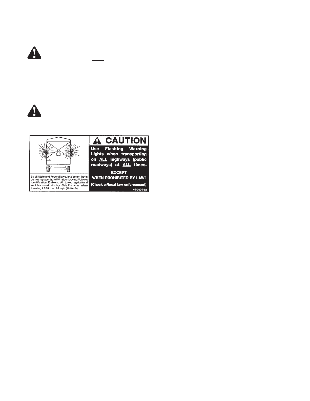
Always install a SMV emblem on forage box for transporting on roadways and keep this emblem clean and bright.
DO NOT step up on any part of the forage box at any time. DO NOT use the PTO guard as a step.
Keep the forage box away from power lines. Contact with electric lines may result in serious injury or death by electrocution!
There are additional Safety precautions associated with Truck mounted units:
If theforage box becomes clogged, shut off the truck, setpark brake, remove keys, keep keys in your possession, and allow all mechanism to stop.
Then, clean or work on the forage box as required.
Always shut off the truck, remove keys, keep keys in your possession to prevent accidental startup or unexpected movement be
fore working on forage box.
There are additional Safety precautions associated with Tractor towed units:
If the forage box becomes clogged, shut offthetractorengine and allow all mechanisms to stop. Disconnect PTO shaft. Then, clean
or work on the forage box as required.
Always shut off power and disconnect PTO shaft from tractor to prevent accidental startup or unexpected movement before work
ing on forage box.
DO NOT step over the power take-off shaft. Stay clear of the PTO at all times.
Keep PTO shaft telescoping tube shields turning freely. Keep PTO master shield on tractor. Replace damaged or missingshields.
Never operate PTO above normal 540 RPM rating. Never
Use only properly rated running gear and tires.
DO NOT tow at speeds in excess of 20 MPH when transporting this forage box. Never exceed a safe travel speed.
MEYER MFG. CORP. PROVIDES GUARDS FOR EXPOSED MOVING PARTS FOR THE OPERATOR’S PROTECTION; HOW
EVER, SOME AREAS CANNOT BE GUARDED OR SHIELDED IN ORDER TO ASSURE PROPER OPERATION. THE OPERA
TOR’S MANUAL AND DECALS ON THE FORAGE BOX ITSELF WARN YOU OF DANGERS AND MUST BE READ AND
OBSERVED CLOSELY!
connect forage box PTO shaft to a 1000 RPM tractor PTO.
-
-
-
-
-
-
Study the Above Safety Rules
FAILURE TO HEED MAY RESULT IN SERIOUS PERSONAL INJURY OR DEATH.
--4-- 8100 Rear Unload
Page 6
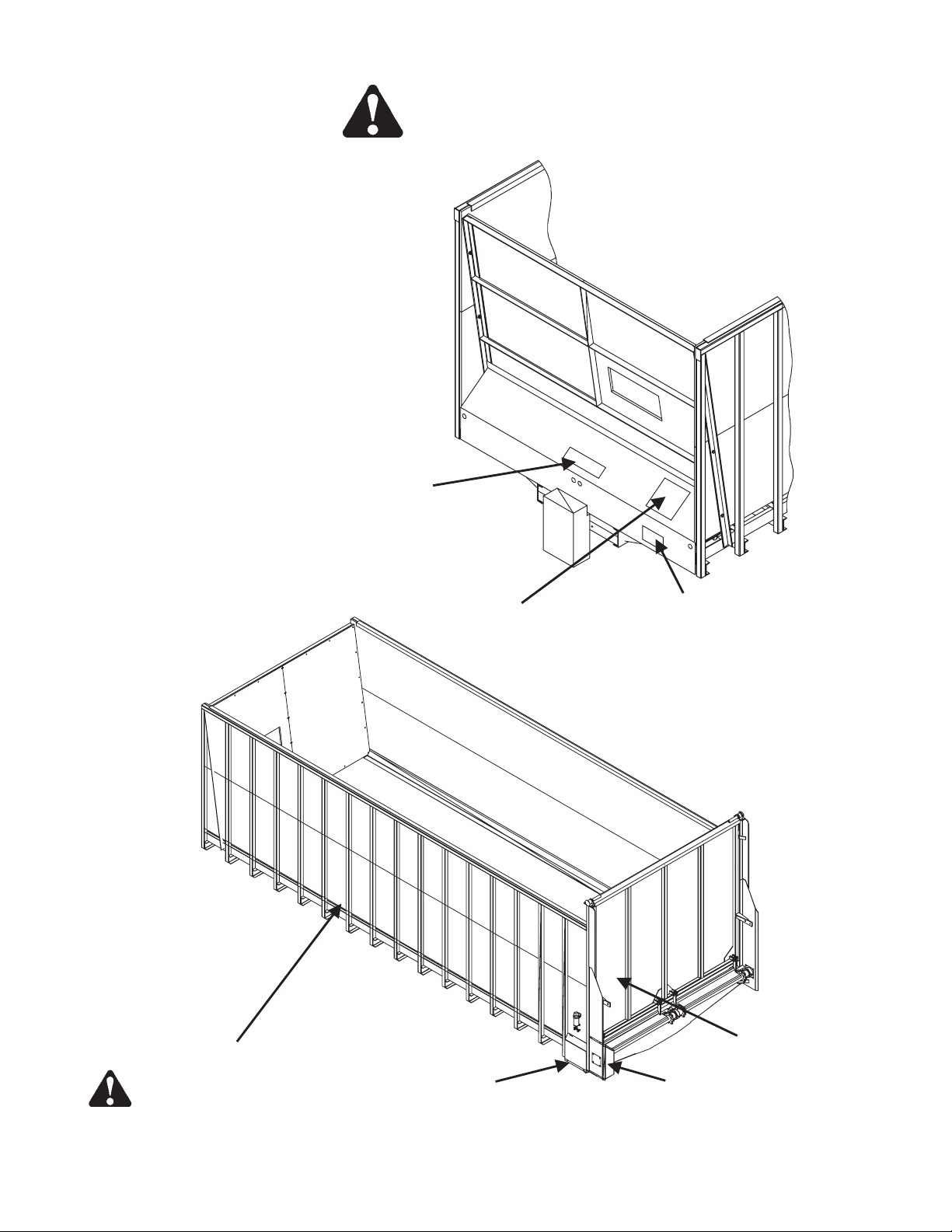
D - on PTO Drive Shaft Guard - Tractor
Pulled MODELS (not shown).
SAFETY FIRST
E
C - both sides
A
F
B
E
CAUTION: READ ALL DECALS ON THE FORAGE BOX AND IN THIS MANUAL. KEEP THESE DECALS CLEAN AND
REPLACE ANY LOST OR DESTROYED DECALS. BECOME FAMILIAR WITHALL TRUCK OR TRACTOR AND FORAGEBOX
CONTROLS.
8100 Rear Unload --5--
G
Page 7
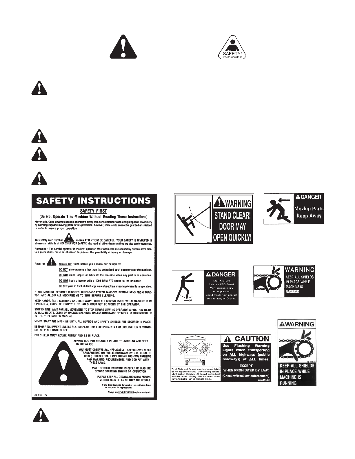
SAFETY FIRST
The Meyer Forage Box is manufactured with operator safety in mind. Located on the forage box are various decals to
aid in operation and warn of danger or caution areas. Pay close attention to all decals on the forage box.
DO NOT REMOVE ANY DECALS. IF DECALS ARE LOST, DAMAGED OR IF FORAGE BOX
IS REPAINTED, REPLACE DECALS. REMEMBER: DECALS ARE FOR YOUR PROTECTION
AND INFORMATION.
A brief definition of signal words that are used in this manual is as follows:
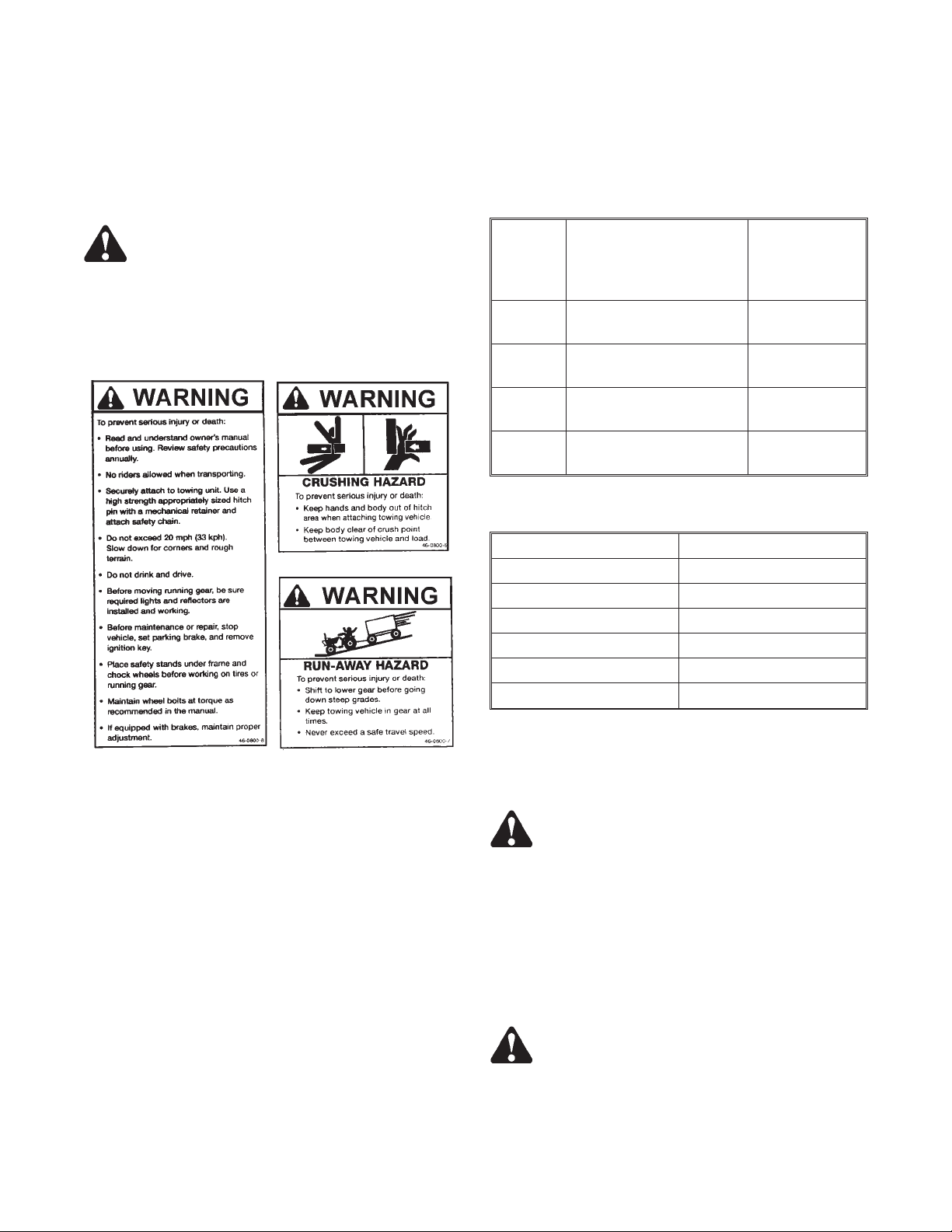
DANGER Indicates an imminently hazardoussituation that, if not avoided, will resultin death or serious injury.
WARNING Indicates a potentially hazardous situation that, if not avoided could result in death or serious injury,
and includes hazards that are exposed when guards are removed.
CAUTION Indicates a potentiallyhazardous situation that, if not avoided mayresult in minor or moderate injury.
DECAL C.
PART NO. 46-0001-20
DECAL B.
PART NO. 46-0011-D
DECAL E.
DECAL D.
PART NO. 46-0004-2
DECAL F.
DECAL A.
PART NO. 46-0001-22
CAUTION: READ ALL DECALS ON THE FORAGE BOX AND IN THIS MANUAL. KEEP THESE DECALS CLEAN AND
REPLACE ANY LOST OR DESTROYED DECALS. BECOME FAMILIAR WITHALL TRUCK OR TRACTOR AND FORAGEBOX
CONTROLS.
PART NO. 46-0001-62
PART NO. 46-0001-4
DECAL G.
PART NO.
46-0001-33
--6-- 8100 Rear Unload
Page 8
PRE-OPERATION
Whenever adjusting, cleaning, lubricating or otherwise
servicing this forage box, you must shutoff and lockout
power to the box. Because this box can be truck
mounted or powered by a tractor, methods vary. On
truck mounted units, the connection between the PTO
and box is permanently installed and not intended to be
disconnected. On trucks, disengage the PTO drive, turn
off the engine, set the parking brake, remove the ignition
keys and keep them in your possession to prevent any
one else from accidentally applying power to the box un
expectedly. On tractor pulled units, the connection
between the tractor PTO and box is by a removable PTO
drive shaft. For tractors, disengage the PTO drive, turn
off the engine, set the brakes and disconnect the PTO
drive shaft from the tractor.
DANGER: DO NOT OPERATE WITHOUT PTO
GUARD ON MACHINE AND ON TRACTOR OR TRUCK.
FAILURE TO HEED MAY RESULT IN SERIOUS PER
SONAL INJURY OR DEATH.
-
-
GUARDS IN OPERATING CONDITION. REPLACE
THEM IF DAMAGED AND NOT TURNING FREELY.
FAILURE TO HEED MAY RESULT IN SERIOUS PER
SONAL INJURY OR DEATH.
DANGER: MAINTAIN PTO DRIVE SHAFT
-
-
Throughout this manual, when directed to shutoff and
lockout power, be familiar with the previously described
procedures for the type of machine you are operating.
References in this manual are made to the PTO drive
shaft and are applicable to tractor pulled MODELS.
Be sure your forage box is properly mounted to the truck
frame or to the wagon running gear. Consult your dealer
if you have any questions about proper installation. A tie
down kit from the manufacturer and illustrated in the
parts listing of this manual is available for wagon applications.
Input speed to the forage box line shaft must be 540 rpm
maximum. On trucks the PTO drive must be reduced to
obtain this speed. For tractors, select the 540 rpm option
according to manufacturers instructions.
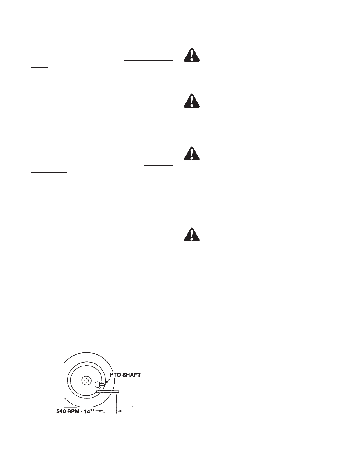
For tractor pull model, set your tractor drawbar to con
form to the standard dimensions shown on the following
illustration. This will ensure that the PTO drive shaft will
not be over extended.
WARNING: INSPECT REGULARLY THAT ALL
CONNECTIONS AND BOLTS ARE TIGHT AND SE
CURE BEFORE OPERATING. FAILURE TO HEED MAY
RESULT IN SERIOUS PERSONALINJURY OR DEATH.
Inspect the forage box for proper adjustments as this will
ensure maximum machine performance. See “Adjustments” section. Grease and oil the forage box as required. See “Lubrication” section.
WARNING: DO NOT OPERATE UNTIL ALL
SHIELDS AND GUARDS ARE IN PLACE AND SECURELY FASTENED. FAILURE TO HEED MAY RESULT IN SERIOUS PERSONAL INJURY OR DEATH.
-
-
Before filling the box, slowly engage the PTO and oper
ate box at idle speed to ensure it is operating properly.
DRAWBAR & PTO RELATIONSHIP
8100 Rear Unload --7--
-
Page 9
TRANSPORTING
On tractor pulled MODELS, always disconnect the PTO
drive shaft from the tractor and return it to the PTO stor
age bracket on the box front before transporting. Failure
to do this may result in equipment damage.
WARNING: INSTALL A SMV EMBLEM ON
REAR OF FORAGE BOX FOR TRANSPORTING ON
ROADWAYS. KEEP THIS EMBLEM CLEAN AND
BRIGHT. FAILURE TO HEED MAY RESULT IN SERI
OUS PERSONAL INJURY OR DEATH.
TRACTOR TOWING SIZE REQUIREMENTS
Use the following chart for calculating the minimum trac
tor weight.
MODEL FORAGE BOX EMPTY
WEIGHT + LOAD = GW
-
8118 5,200 + _____ = _____ 2/3 of box
8120 5,400 + _____ = _____ 2/3 of box
8122 5,700 + _____ = _____ 2/3 of box
8124 6,200 + _____ = _____ 2/3 of box
MATERIAL ESTIMATED WEIGHT PER CUBICFOOT
MATERIAL LBS / CU. FT.
SOYBEANS 47 LBS.
COTTON SEED DRY 20 LBS.
CORN (SHELLED) 45 LBS.
CORN SILAGE 30 LBS.
HAYLAGE 20 LBS.
SAWDUST 17 LBS.
MINIMUM
TRACTOR
WEIGHT UP
TO 20 MPH
gross weight
gross weight
gross weight
gross weight
-
Be sure and observe that the rear discharge door is
latched closed before traveling on roadways.
If you will travel on public roads and it is legal to do so,
you must know all rules governing such operation. This
will include lightingand brake requirements inaddition to
traffic rules. You may also be required to install a safety
chain device on the running gear.
SOURCE: ASAE
NOTE: HEAPED LOADS HAVE SIGNIFICANTLY
HIGHER CAPACITIES
WARNING: MAKE CERTAIN EVERYONE IS
CLEAR OF EQUIPMENT BEFORE APPLYING
POWER. FAILURE TO HEED MAY RESULT IN SERI
OUS PERSONAL INJURY OR DEATH.
Your running gear for tractor pulled model probably has
a telescoping tongue for convenience to hitch up. Always
back up and lock this tongue in the operating position af
ter hitching.
WARNING: YOU MUST OBSERVE ALL AP
PLICABLE TRAFFIC LAWS WHEN TRANSPORTING
ON PUBLIC ROADWAYS. CHECK LOCAL LAWS
FOR ALL HIGHWAY LIGHTING AND MARKING RE
-
-
-
-
--8-- 8100 Rear Unload
Page 10
QUIREMENTS. FAILURE TO HEED MAY RESULT IN
SERIOUS PERSONAL INJURY OR DEATH.
WARNING: DO NOT TOW
CESS OF 20 MPH. FAILURE TO HEED MAY RESULT
IN SERIOUS PERSONAL INJURY OR DEATH.
Operating speed is dictated by the terrain over which you
are traveling. Always use caution. Avoid traveling on
slopes or hills that are unsafe.
CAUTION: USE FLASHING WARNING LIGHTS
WHEN TRANSPORTING ON ALL PUBLIC ROAD
WAYS, EXCEPT WHEN PROHIBITED BY LAW.
AT SPEEDS IN EX
-
-
Check for traffic constantly. Be sure you can see that no
one is attempting to pass you and that all traffic is sufficiently clear from you before making any turns.
TRUCK MOUNT FORAGE BOXES
Depending on the make and model of truck it may be
necessary to install a light converter (MEYER PART
#56-0028). Converter will allow signal lights and brake
lights to operate according to DOT lighting standard. Call
factory for more information.
8100 Rear Unload --9--
Page 11
REAR UNLOAD OPERATION
Whenever adjusting, cleaning, lubricating or otherwise
servicing this forage box, you must shutoff and lockout
power to the box. Because this box can be truck
mounted or powered by a tractor, methods vary. On
truck mounted units, the connection between the PTO
and box is permanently installed and not intended to be
disconnected. On trucks, disengage the PTO drive, turn
off the engine, set the parking brake, remove the ignition
keys and keep them in your possession to prevent any
one else from accidentally applying power to the box un
expectedly. On tractor pulled units, the connection
between the tractor PTO and box is by a removable PTO
drive shaft. For tractors, disengage the PTO drive, turn
off the engine, set the brakes and disconnect the PTO
drive shaft from the tractor.
Throughout this manual, when directed to shutoff and
lockout power, be familiar with the previously described
procedures for the type of machine you are operating.
References in this manual are made to a PTO drive shaft
and are applicable to tractor pulled MODELS.
WARNING: MAKE CERTAIN EVERYONE IS
WELL CLEAR OF EQUIPMENT BEFORE APPLYING
POWER. FAILURE TO HEED MAY RESULT IN SERIOUS PERSONAL INJURY OR DEATH.
Tractor Pulled:
Always park the forage box and unloading tractor
in a straight line. Minimize the unloading angle on
the PTO drive shaft
to prevent wearing of universal
joints when connected to the unloading tractor
PTO. Shift the unloading tractor to “Neutral” or
“Park”. Set the brakes and turn power off. Remove
the PTO drive shaft
from the forage box PTO stor
age bracket and connect it to the tractor PTO. Be
sure the PTO yoke is securely locked to the tractor
PTO.
WITH EXTREME FORCE. KEEP ALL PERSONS
WELL CLEAR OF THE FORAGE BOX AND UN
LOADING AREA. FAILURE TO HEED MAY RESULT
IN SERIOUS PERSONAL INJURY OR DEATH.
From the operator’s seat, restart, and SLOWLY
the PTO to start the apron chains and to open the rear
door. Once the door opens, regulate the discharge flow
with the engine speed. Do not operate above rated en
gine PTO speed.
-
Unloading is best observed from the operator’s seat.
Keep moving the forage box forward to prevent silage
from being carried underneath into the main apron chain
return area.
The front of the box has a plexiglass window for conve
nient observation.
WARNING: DO NOT STEP OVER THE PTO
DRIVE SHAFT. STAY WELL CLEAR OF THE PTO AT
ALL TIMES. FAILURE TO HEED MAY RESULT IN
SERIOUS PERSONAL INJURY OR DEATH.
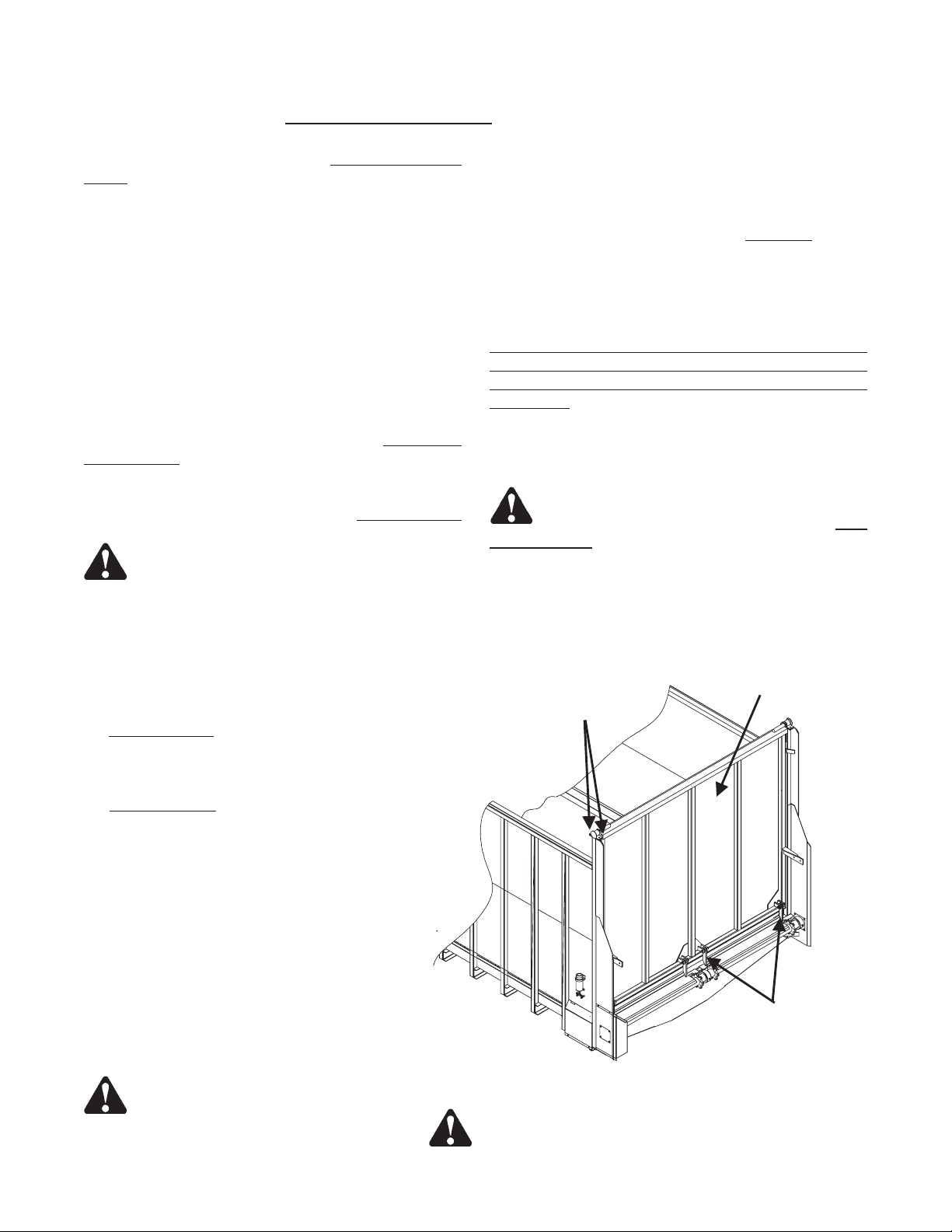
REAR
DISCHARGE
DOOR
HINGE BOLTS
-
engage
-
-
Make sure all persons are well clear of the forage
box and the unloading area.
The rear discharge door opens automatically by
releasing its latches as the main aprons begin to
move. The rear discharge door can spring open
with extreme force when its latches release. See
figure 1. Pressure of forage against the rear door
causes it to spring open very quickly.
WARNING: THE REAR DISCHARGE
DOOR CAN SPRING OPEN QUICKLY AND
REAR DOOR
LATCHES
FIGURE1. REAR OPENING DISCHARGE DOOR
CAUTION - QUICK RELEASE
--10-- 8100 Rear Unload
Page 12

WARNING: DO NOT STEP UP ON ANY PART
OF THE FORAGE BOX AT ANY TIME. FAILURE TO
HEED MAY RESULT IN SERIOUS PERSONAL INJURY
OR DEATH.
DANGER: NEVER ENTER THE FORAGE BOX
FOR ANY REASON WITHOUT FIRST SHUTTING OFF
AND LOCKING OUT POWER. FAILURE TO HEED
MAY RESULT IN SERIOUS PERSONAL INJURY OR
DEATH.
The unloading process described is to be performed by
the operator alone. This will eliminate unexpected
“start-ups” and minimize other hazards that could result
by more than one person in control. If the forage box
should become clogged, shut off all power to the forage
box and wait for all motion to stop. Shut off and lockout
power. Then clean out the machine.
When finished unloading reduce engine speed to idle
and disengage the PTO drive. Pull the rear unload box
straight ahead to pull the door away from the unloaded
pile of forage. When free, gravity will allow the door to
swing shut and the door latches will engage the apron
chain links to secure it shut. Observe that this happens
properly.
Tractor Pulled:
Set the brakes and turn the tractor “OFF”. When all
movement has stopped, disconnect the PTO drive shaft
from the tractor and return it to its storage bracket. Secure it with the rubber tie down strap.
WARNING: DISCONNECT PTO DRIVE SHAFT
BEFORE CLEANING, ADJUSTING, LUBRICATING
OR SERVICING THIS MACHINE. FAILURE TO HEED
MAY RESULT IN SERIOUS PERSONAL INJURY OR
DEATH.
Never enter the forage box for any reason if there is any
possibility of power being applied to the unit.
Allow box to completely clean out the last load of forage.
It is recommended to lube the rear unload box before
storage to exclude moisture from bearings. Apply oil to
roller chain drives with gravity oil luber and to the apron
chains with a brush. This is also a good time to inspect all
adjustments and check for parts that need repair or re
placement. Performing these tasks now will guarantee
that the box is ready for use at the beginning of the next
season.
Never use “live” power to aid in the clean-out of a
clogged machine. If any mechanism fails, move the for
age box to a safe work area and then repair the mecha
nism before proceeding with unloading of the forage. If
repairs require removal of forage from inside the forage
box, remove the rear discharge door (bolted hinges on
top of each side) and empty the forage manually by hand
through the rear opening.
8100 Rear Unload --11--
-
-
-
Page 13

This Page Intentionally Blank
--12-- 8100 Rear Unload
Page 14
LUBRICATION
WARNING: SHUT OFF AND LOCK OUT
POWER BEFORE CLEANING, ADJUSTING, LUBRI
CATING OR SERVICING THIS MACHINE. FAILURE
TO HEED MAY RESULT IN SERIOUS PERSONAL IN
JURY OR DEATH.
DAILY LUBRICATION
(every 8-10 loads)
It is recommended to lube the forage box before storage
to exclude moisture from bearings. Apply oil to roller
chain drives with the gravity oil luber and to the main
-
apron chains with a brush.
-
It is also a goodtime to inspect all adjustments andcheck
for parts that need repair or replacement. Performing
these tasks now will guarantee that the forage box is
ready for use at the beginning of the next season.
Grease (2) PTO drive shaft universal joints (not il
lustrated). Grease (1) PTO drive shaft telescoping
Shaft and tube. Zerk accessible through the plastic
guards (not illustrated)
Oil (2) roller chains on apron drive. This is done by
opening the ball valve on the gravity oiler while
unloading, once per day.
WARNING: DO NOT STAND BEHIND UNIT
WHILE PERFORMING THIS OPERATION.
Refill the gravity oiler atthe beginning of each day.
Grease two jack shaft bearings. Lube line for bearing under box is routed to the side of the box for convenience.
Oil (4) rear gate latch pivot bolts.
Maintain oil in the gearbox at the check plug level.
-
Grease (3) main apron shaft bearings.
BEGINNING OF CROP MAINTENANCE
(approximately 100-150 loads)
Change oil in the gear box after the first season of use
and yearly thereafter. Use #80-90 wt. Gear Lube Oil.
Lighter oil may be usedin temperatures lower than 20° F.
END OF CROP CLEANUP AND MAINTENANCE
Allow box to completely clean out last load of forage.
Clean out all forage material from inside the box and on
the outside of the box.
8100 Rear Unload --13--
Page 15
(UNDER BOX)
BOTH SIDES
SHOWN W/SHIELD REMOVED
LUBRICATION DIAGRAM
--14-- 8100 Rear Unload
Page 16
ADJUSTMENTS
WARNING: SHUT OFF AND LOCK OUT POWER BEFORE CLEANING, ADJUSTING, LUBRICATING OR
SERVICING THIS MACHINE. FAILURE TOHEED MAY RESULT IN SERIOUS PERSONAL INJURYOR DEATH.
Correct tension on the apron chains is when the
apron chain slat is 1/8” to 1/4” off the return slides (three
feet from the front of the box). To tighten chains, tighten
the adjuster bolts at each end of the front sprocket
shafts. Each apron chain has its own sprocket shaft.
Tighten the adjuster bolts at each end of the shaft
equally.
The roller chain drives are tensioned by automatic spring
loaded tension blocks. Periodically eye bolts will need to
be adjusted to maintain proper spring tension. Springs
should be stretched to obtain approximately 1/16” gap
between windings.
BOTH SIDES
Front Shields Removed To Illustrate Service Components.
Do Not Remove This Shield To Perform The Service.
ADJUSTMENT DIAGRAM
8100 Rear Unload --15--
Page 17
REPAIR PARTS
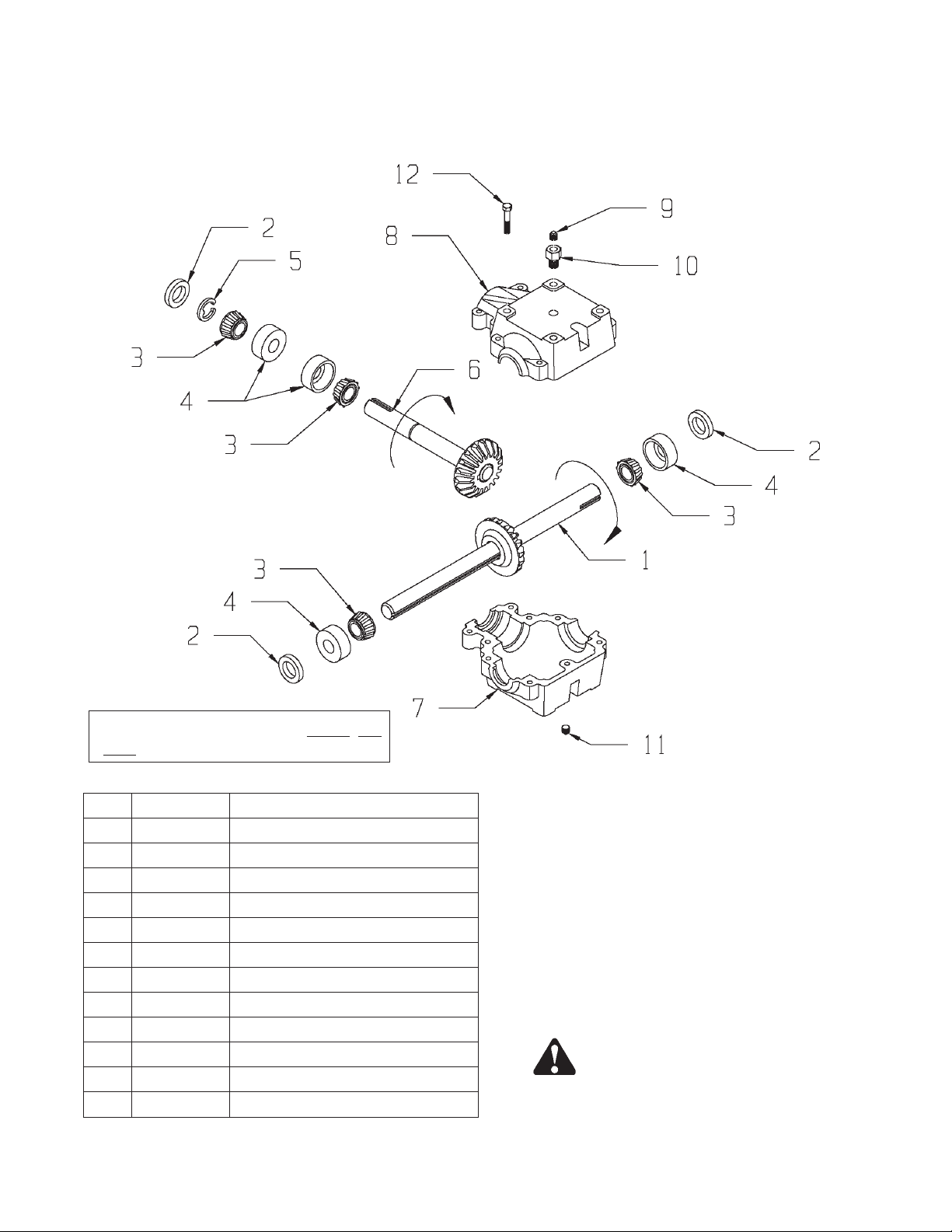
#19-0038 2:1 RATIO GEARBOX
Use #80-90 wt. Gear Lube Oil ONLY. DO
NOT USE GREASE FOR LUBRICANT.
KEY PART NO. DESCRIPTION
1 19-0034-4 Output Shaft/Gear Assembly
2 19-0018-2 Seal
3 19-0018-3 Bearing Cone
4 19-0016-3 Bearing Cup
5 19-0018-4 Retaining Ring
6 19-0034-3 Input Shaft/Gear Assembly
7 19-0043-1 Gearbox Casting (Tapped Holes)
8 19-0041-2 Gearbox Casting (Thru Holes)
9 19-0002-17 Vent Plug, 5 PSI
10 19-0023-2 Bushing, ½-14 NPT
11 19-0016-5 Plug, ½-14 NPT
12 19-0016-11 Bolt, 3/8-16 x 1.50 SHCS
NOTE: Gearbox may be flipped 180 degrees if
input power rotation is opposite standard rota
tion. (Truck mount boxes only)
CAUTION: VERIFY CORRECT DRIVE
ROTATION BEFORE OPERATING. FAILURE
TO DO SO MAY RESULT IN SEVERE EQUIP
MENT DAMAGE.
-
-
--16-- 8100 Rear Unload
Page 18
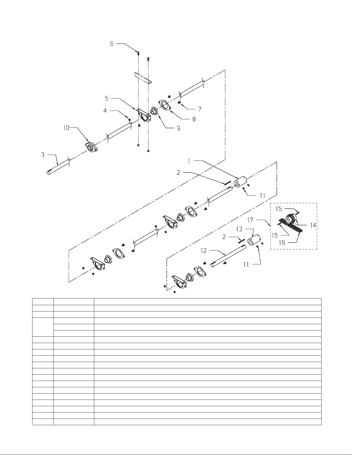
MAIN DRIVE SHAFT (PTO DRIVE)
KEY PART NO. DESCRIPTION
1 37-0007 Shaft Coupler 1-1/4” Bore
2 35-0014 Key, ¼ x ¼ x 4-1/2”
3 23-0094 8118 Center Drive Shaft, 1-1/4” x 186”
23-0100 8120 Center Drive Shaft, 1-1/4” x 202”
23-0091 8122/8124 Center Drive Shaft, 1-1/4” x 234”
4 810-3816-Z 3/8-16 Spin Locknut
5 14-0003-1 1-1/4” Pillow Block Flange
6 851-3816-1Z Bolt, 3/8-16 x 1, Machine Bolt Grade 5
7 850-3816-1Z Bolt, 3/8-16 x 1, Carriage Bolt Grade 5
8 14-0003-2 1-1/4” Two Bolt Flange
9 14-0002-3 1-1/4” Bearing w/Lock Collar
10 14-0046 1-1/4” Two Hole Flange Cast Bearing
11 827-3118-.38 Set Screw, 5/16-18 x .375
12 23-0098 8124 Center Drive Shaft Ext, 1-1/4” x 32”
13 37-0007 Shaft Coupler 1-1/4” Bore (Prior to Serial #0781227)
14 37-0017-1 1-1/4" Bore Chain Coupler
15 35-0012 Key, 1/4x1/4x1-1/2"
16 37-0013-2 Coupler Chain
17 37-0020 Chain Coupler Assembly 1-1/4" W/Keys (Serial #0781227 & Later)
8100 Rear Unload --17--
Page 19

#18-0119 (OPTIONAL) UNIVERSAL JOINT TELESCOPING ASSEMBLY
W/GUARD
KEY PART NO. DESCRIPTION
18-0117 Joint Assembly
1 18-0117-1-1 1 3/8-6 Spline Yoke ASGE
2 18-0117-1-2 Cross and Bearing Kit
3 18-0117-1-3 Inboard Yoke and Bar Welded
Assy.
4 18-0117-2-1 Inboard Yoke, Tube and
Sleeve Welded Assy.
6 18-0119-1-1 Overrunning Clutch Assembly
7 18-0117-1-4 Shield Cone 5-Rib
8 918-0208-2-4 Bearing Ring SC25
9 18-0117-1-6 Outer Shield Tube Oval
10 18-0117-2-3 Inner Shield Tube Round
11 918-0208-2-9 Screw-Included in Item #7
12 918-0208-2-7 Safety Chain
13 918-0208-2-8 Decal Outer-Included in Item
#9
KEY PART NO. DESCRIPTION
14 918-0208-1-10 Decal Inner-Included in Item #4
15 18-0117-1-1-1 ASGE Collar Kit-Included in
Item #1
16 18-0117-1 Tractor Male Half Complete
17 18-0119-1 Implement Female Half Shaft
Complete
18 24-0118 Shield Assembly (Optional
PTO Drive)
19 24-0118-1 PTO Shield Welded Bracket
20 24-0118-2 PTO Flexible Shield
21 32-0025 PTO Flexible Shield Clamp
22 38-0016 5/16” Roll Pin (Optional PTO
Drive)
23 35-0021 Key, 1/4 x 1/4 x 1-3/4
24 18-0117-1-7 Shield Cone, 4-Rib
--18-- 8100 Rear Unload
Page 20

GEARBOX & CHAIN DRIVE
8100 Rear Unload --19--
Page 21

GEARBOX & CHAIN DRIVE
KEY PART NO. DESCRIPTION
1 30-0002 Zerk, 1/8 NPT Straight
2 930-3602 68F-04X02 Male Connector Brass Compression
3 14-0044 Bearing, 2” Pillow Block
4 933-3636 46” Copper Grease Line
5 25-8006-1 Gearbox Mount Channel
6 11-0117 #80-59 Roller Chain
7 10-0080 80B12 1-3/8” Bore 5/16” Kwy Sprocket
8 35-0013 Key, 5/16 x 5/16 x 1.5
9 19-0038 Superior Gearbox 2:1
10 35-0014 Key, ¼ x ¼ x 4.5
11 851-7510-1.75Z Bolt, 3/4-10 x 1-3/4” Hex Head Machine Bolt
12 912-0017 1-3/8” Nylon Roller Complete
12A 912-0015-1 Nylon Roller Only
12B 912-0015-2 Inner Sleeve
13 851-7510-4Z Bolt, 3/4-10 x 4 Hex Head Machine Bolt
14 929-3601 Spring, Extension
15 813-3118-Z Nut, 5/16-18
16 933-3804 5/16 x 5” Eyebolt #124032, 5” Overall 3” Threads ZN
17 23-0097 Jack shaft, 2” x 59”
18 814-7510-Z Nut, 3/4-10 Center Locknut
19 25-8007-1 80 Chain Tightener Weldment
20 851-6311-2.5Z Bolt, 5/8-11 x 2-1/2 Hex Head Machine Bolt
21 805-0063-Z Washer, 5/8” Flat
22 810-5013-Z Nut, ½-13 Spin Locknut
23 806-0050-Z Washer, ½ Internal Tooth
24 11-0123 #120-37 Roller Chain
25 805-0063-Z Washer, 5/8” Flat
26 851-5013-1.25Z Bolt, ½-13 x 1.25 Hex Head Machine Bolt
27 910-0003 Sprocket, 80B45, 2” Bore, ½” KWY
28 35-0024 Key, ½” x ½” x 2-1/2” (1045 Mat)
29 912-0016 7/8” Nylon Roller Complete
29A 912-0016-1 Nylon Roller Only
29B 912-0016-2 Inner Sleeve
30 10-0085 Sprocket, 120B9, 2” Bore ½” KWY
31 810-6311-Z Nut, 5/8-11 Spin Locknut
32 25-8031-1 120 Chain Tightener Weldment
--20-- 8100 Rear Unload
Page 22

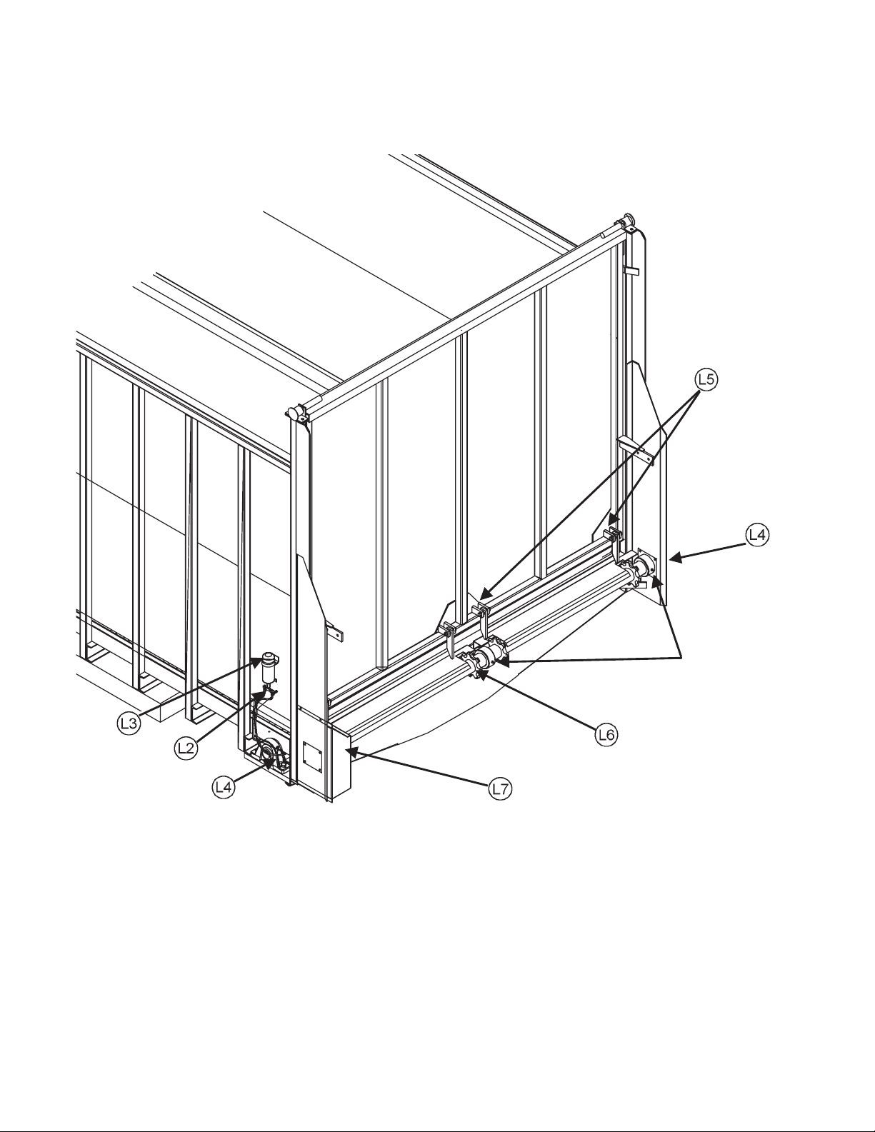
HYDRAULIC PLUMB TO THE FRONT
KEY PART NO. DESCRIPTION
1 55-0088 Hydraulic Motor
2 55-0048 5/8-3/4" Adapter O-Ring Base
3 55-0007-B 3/4" Check Valve
4 29-0012 Spring
5 55-0033 Clamp Assembly
6 55-0034 ½" 2-Wire x 120" Hose Assy.
7 55-0013 Pioneer Coupler Male Tip
8 25-0249-1 Holder For Hydraulic Hose Ends
9 25-0209 Hydraulic Hose Bracket
10 851-3816-1Z Bolt, 3/8-16 x 1" Hex Head
11 35-0019-H Key, 1/4 x 1/4 x 1-1/4" (Hard)
W/Rounded Ends
12 25-8042-1 Hydraulic Motor Mount Bracket,
Rear
13 37-0012 Coupler 1" to 1-1/4" (Prior to Se
rial #0781227)
14 35-0021 Key, 1/4 x 1/4 x 1-3/4"
15 25-0210-4 Hydraulic Pipe Holder Clamp
16 55-0029 2-Wire 3/4" Hose x 36" Long
17 55-0030 3/4" Black Steel Coupler
KEY PART NO. DESCRIPTION
18 55-0062 3/4" Hydraulic Pipe x 161" -
55-0024 3/4" Hydraulic Pipe x 185" -
55-0022 3/4" Hydraulic Pipe x 209" -
55-0020 3/4" Hydraulic Pipe x 233" -
19 55-0079 3/4" Black Tee Fitting
20 55-0081 3/4" Steel Plug
21 851-3816-2.25HHCS 3/8-16 x 2-1/4"
22 815-3816-Z 3/8-16 Nylon Insert Locknut
23 37-0013-1 1" Bore Chain Coupler
24 37-0017-1 1-1/4" Bore Chain Coupler
25 37-0013-2 Coupler Chain
26 35-0019-H Key, 1/4x1/4x1-1/4" (Hard)
27 35-0021 Key, 1/4x1/4x1-3/4"
28 37-0019 Chain Coupler Assembly 1" to
8118
8120
8122
8124
W/Rounded Ends
1-1/4" W/Keys (Serial #0781227
& Later)
8100 Rear Unload --21--
Page 23

HYDRAULIC DRIVE (OPTIONAL FRONT MOUNT) #8100 - HYD
KEY PART NO. DESCRIPTION
1 55-0088 Hydraulic Motor
2 55-0048 5/8-3/4" Adapter ORB
3 55-0007-B 3/4" Check Valve
4 29-0012 Spring
5 55-0033 Clamp Assembly
6 55-0034 1/2" 2-Wire x 120" Hose
Assembly
7 55-0013 Pioneer Coupler Male Tip
8 25-0249-1 Hydraulic Hose End Holder
9 25-0209 Hose Hanger Bracket
10 851-3816-1Z Bolt 3/8-16x1" Hex Head
11 35-0019-H Key, 1/4x1/4x1-1/4" (Hard)
W/Rounded Ends
12 25-8041-1 Hydraulic Motor Mount Bracket
KEY PART NO. DESCRIPTION
13 37-0012 Welded Coupler 1" to 1-1/4"
(Prior to Serial #0781227)
14 35-0021 Key, 1/4x1/4x1-3/4"
15 25-8040-1 Motor Bracket Cover
16 55-0085 1/2x5/8" ORB Straight Fitting
17 55-0044 3/4x1/2" Steel Hex Bushing
18 37-0013-1 1" Bore Chain Coupler
19 37-0017-1 1-1/4" Bore Chain Coupler
20 37-0013-2 Coupler Chain
21 35-0019-H Key, 1/4x1/4x1-1/4" (Hard)
W/Rounded Ends
22 35-0021 Key, 1/4x1/4x1-3/4"
23 37-0019 Chain Coupler Assembly 1" to
1-1/4" W/Keys (Serial #0781227
& Later)
--22-- 8100 Rear Unload
Page 24

APRON
8100 Rear Unload --23--
Page 25

APRON
KEY PART NO. DESCRIPTION
1 851-3816-1Z Bolt, 3/8-16 x 1" Hex Head
2 24-8002 Front Drive Shield (Mechanical Truck Mount)
3 815-3816-Z 3/8-16 Nylon Locknut
4 24-8001 Front Apron Chain Shield
5 25-8009 Apron Chain Tightener Bolt
6 10-0075 Idler Sprocket w/Bushing
13-0018 Bushing, 1-1/4" ID x 1-5/8" OD x 1-1/2" Long
7 25-8010 Tightener Block Weldment
8 851-2520-1Z Bolt, 1/4-20 x 1" Hex Head
9 23-0095 Left Hand Idler Shaft Assembly
10 11-0125 Main Apron Chain Assembly (24 Ft.) 667XH
11-0107 Main Apron Chain Assembly (22 Ft.) 667XH
11-0131 Main Apron Chain Assembly (20 Ft.) 667XH
11-0121 Main Apron Chain Assembly (18 Ft.) 667XH
11 11-0107-2 Pintle Chain Link-D667
12 11-0107-6 Rivet, 7/16 x 1"
13 11-0107-5 Slat
14 11-0107-3 Attachment Link-D667XH
15 810-5013-Z ½-20 Spin Locknut
16 14-0041 RH/LH Main Drive Shaft Bearing Assembly
17 30-0002 1/8" NPT Straight Zerk
18 23-0096 Main Drive Shaft Assembly
19 851-5013-1.25Z Bolt, ½-13 x 1-1/4" Hex Head
20 30-0009 Coupler 1/8" NPT x 3/4" Long
21 11-0107-1 Slat w/Attachment Links
22 30-0006 1/8" NPT x 90 Degree Zerk
23 23-0090 RH Idler Shaft Assembly
24 810-2520-Z 1/4-20 Spin Locknut
25 30-0016 1/8" NPT Close Nipple
26 701-.75-1.75-16 Chain Return Slide Rail (As Required)
701-.75-1.75-18 Chain Return Slide Rail (As Required)
701-.75-1.75-20 Chain Return Slide Rail (As Required)
27 25-8000-1 Front Gate Center Support
28 14-0048 Replacement Split Center Bearing Assembly
29 100-8020-65 Front Stringer Support Plate
--24-- 8100 Rear Unload
Page 26

8100 MAIN BODY
8100 Rear Unload --25--
Page 27

8100 MAIN BODY
KEY PART NO. DESCRIPTION
1 100-8022 8124 Main Frame & Side Assembly
100-8020 8122 Main Frame & Side Assembly
100-8021 8118 Main Frame & Side Assembly
100-8023 8120 Main Frame & Side Assembly
2 49-0089 Plexiglass Viewing Window
3 100-8010-8 Fiberglass Plywood Panel (with Viewing Hole) 96.5 x 69.75"
4 708-96.5-69.75 Fiberglass Plywood Panel 96.5 x 69.75"
5 100-8010 Front Gate Assembly Complete
100-8010-1 Front Gate Welded Frame Only
6 851-5013-1.5Z ½-13 x 1-1/2" Hex Head Bolt
7 810-5013-Z ½-13 Spin Locknut
8 24-8005-1 Shield Bottom Seal, 120 Drive Chain
9 33-1008 Plywood Tee Molding (By the foot)
10 709-48-206.5 8118 Superslick Floor Panel 48 x 206-1/2"
709-48-222.5 8120 Superslick Floor Panel 48 x 222-1/2"
709-48-254.5 8122 Superslick Floor Panel 48 x 254-1/2"
709-48-286.5 8124 Superslick Floor Panel 48 x 286-1/2"
11 708-70.75-264 Fiberglass Plywood Side Panel 70.75 x 264" (8118, 8120, 8122)
708-70.75-296 Fiberglass Plywood Side Panel 70.75 x 296" (8124)
12 829-14-1.88 1/4-14 x 1-7/8" Self Tapping Screw
13 850-25201.25Z 1/4-20 x 1-1/4" Carriage Bolt
14 810-2520-Z 1/4-20 Spin Locknut
15 803-12-.63 #12 Phillips Pan Head Screw
17 25-8008 Fender (Optional on Truck Mount Models)
18 49-0085 Front Gate Belting
19 24-8005-2 Shield, 120 Drive Chain
20 24-8003 Shield, 120 Drive Chain
21 24-8004 Shield, Jack Shaft
22 25-8020-1 LH Rear/Center Floor Chain Guide 96"
25-8029-1 LH Center Floor Chain Guide 48"
23 25-8024-1 Center Rear Floor Chain Guide 96"
25-8027-1 Center Floor Chain Guide 96"
25-8028-1 Center Floor Chain Guide 48"
24 25-8022-1 RH Center Chain Guide 96"
25-8030-1 RH Center Chain Guide 48"
25 25-8021-1 Center Floor Chain Guide End Cap
26 25-8023-1 Right Floor End Cap
27 25-8019-1 Left Front Floor End Cap
28 100-8070 End Cap
29 825-3118-1.5 5/16-18x1-1/2” Self Threading Floor Screw
30 25-8203-1 Front Floor Cover
--26-- 8100 Rear Unload
Page 28

REAR DOOR
8100 Rear Unload --27--
Page 29

REAR DOOR
KEY PART NO. DESCRIPTION
1 851-5013-2.5Z ½-13 x 2.5 Hex Head Machine Bolt
2 828-0050-Z ½" SAE Flat Washer
3 100-8012-7 Back Gate Latch
4 814-5013-Z ½-13 Center Locknut
5 851-2520-.75Z 1/4-20 x .75 Hex Head Machine Bolt
6 49-0086 Back Gate Belting
7 25-8005-1 Belting Attaching Strip, Right Hand
8 25-8005-2 Belting Attaching Strip, Left Hand
9 100-8013 Back Gate Assembly Complete, (Standard Height Gate 82-1/2")
100-8060 Back Gate Assembly Complete, (High Back Gate 94-1/2")
9A 100-8013-1 Back Gate Welded Assembly, (Standard Height Gate 82-1/2")
100-8060-1 Back Gate Welded Assembly, (High Back Gate 94-1/2")
10 708-95.5-80.25 Fiberglass Plywood Panel, 95.5 x 80.25"
11 810-5013-Z ½-13 Spin Locknut
12 851-5013-1.5Z ½-13 x 1.5 Hex Head Machine Bolt
13 100-8012-15 Back Gate Hinge Weldment
14 100-8013-6 Gate Stop
15 815-5013-Z ½-13 Nylon Locknut
16 810-2520-Z 1/4-20 Spin Locknut
17 100-8062 Right Pivot Extension Assembly (High Gate Only)
18 100-8063 Left Pivot Extension Assembly (High Gate Only)
19 100-8060-1-7 High Gate Top Panel (High Gate Only)
--28-- 8100 Rear Unload
Page 30

OPTIONAL DOUBLE DOOR
8100 Rear Unload --29--
Page 31

OPTIONAL DOUBLE DOOR
KEY PART NO. DESCRIPTION
1 100-8100-20 Right Hand Door Welded Assembly
100-8100 Right Hand Door Complete
2 100-8101-20 Left Hand Door Welded Assembly
100-8101 Left Hand Door Complete
3 100-8102 Double Door Gate Hinge Pin Weldment
4 100-8103 Double Door Bottom Linkage Arm Weldment
5 100-8104 Double Door Linkage Pipe Weldment
6 100-8105 Double Door Linkage Tie Rod Weldment
7 100-8106 Double Door Linkage Clevis Weldment
8 100-8107 Double Door Linkage Pivot Shaft Weldment
9 100-8108 Double Door Solenoid Mount Bracket
10 24-8100 Double Door #120 Chain Shield
11 55-0154 Double Door Air Chamber
12 16-0027 Double Door ½" Swivel Eyelet
13 14-0002-3 1-1/4" Bearing W/Lock Collar
14 14-0003-1 1-1/4" 2-Hole Pillow Block Flange
15 14-0003-2 1-1/4" 2-Hole Plain Flange
16 100-8100-6 Double Door Latch
17 100-8100-16 Door Panel
THE FOLLOWING ITEMS ARE NOT ILLUSTRATED
49-0033 Double Door Back Gate Belting 5" x 42"
55-0150 3/8" Air Line (25’ Required)
55-0151 3/8" Hex Plug
55-0152 3/8 x 3/8 x 90 Degree Elbow
55-0153 3/8" x 1/8" Connector
55-0155 12 Volt Solenoid Valve
--30-- 8100 Rear Unload
Page 32
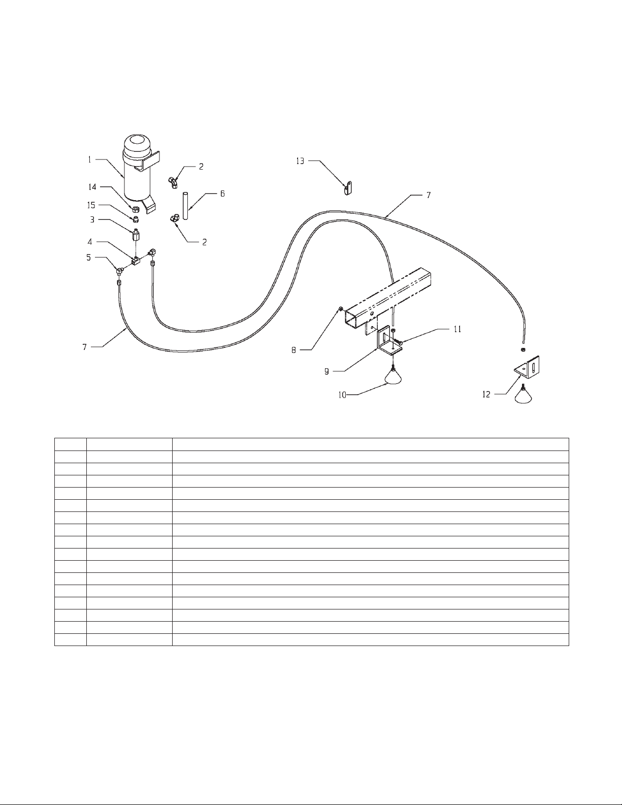
ROLLER CHAIN OILER
KEY PART NO. DESCRIPTION
1 33-8001-1 Oil Reservoir
33-8002 8100 Oil Reservoir Complete w/Fittings
2 30-0015 1/4 x 90 Degree Elbow
3 33-8000-6 Ball Valve
4 33-8001-3 Brass Tee
5 33-8000-5 90 Degree Brass Compression Fitting
6 33-8001-2 Oiler Site Tube
7 952-0001-1-21 Tubing, 5/32" Nylon
8 810-3118-Z 5/16-18 Spin Locknut
9 33-8000-10 Brush Holder
10 952-0001-1-25 Brush Assembly with 5/32" Insert & ½-20 Nut
11 851-3118-1Z 5/16-18 x 1" Hex Head Bolt
12 33-8000-7 #80 Chain Brush Holder, 3/16x1-1/2x10-3/8"
13 08-0050 5/16" Loom Clamp
14 33-8001-4 1/8" NPT Nut
15 33-8001-5 1/8" NPT Nipple
8100 Rear Unload --31--
Page 33

HIGHWAY TRANSPORT AG LIGHTS
KEY PART NO. DESCRIPTION
1 56-0009 7-Way “Stor-A-Way” (Optional)
2 56-0005 Coil Cable Assembly (Optional)
2A 56-0012 7-Contact Plug End
3 56-0005-1 4 Pole Plug Only (Optional)
4 56-0004 #1232 4-Way Socket (4 Pin)
5 56-0001-3 Bezel Blank, Black
6 32-0026 14” Nylon Tie Strap
7 56-0003 Ag Light Harness w/Tri Plugs (Prior to Serial #0681201)
56-0032 Ag Light Harness W/Module (Serial #0681201 & Later)
8 56-0002 Dual Light RH w/Tri Plug (Prior to Serial #0681201)
56-0031 Dual Light RH w/4-Plug (Serial #0681201 & Later)
8A 56-0022 Truck Mount Dual Light RH w/Tri Plug (Prior to Serial #0681201)
56-0031-TR Truck Mount Dual Light RH w/4-Prong (Serial #0681201 & Later)
9 56-0001 Dual Light LH w/Tri Plug (Prior to Serial #0681201)
56-0030 Dual Light LH w/4-Plug (Serial #0681201 & Later)
9A 56-0021 Truck Mount Dual Light LH w/Tri Plug (Prior to Serial #0681201)
56-0030-TR Truck Mount Dual Light LH w/4-Prong (Serial #0681201 & Later)
10 56-0001-4 #1157 Bulb
11 32-0024 3/8” Plated Loom Clip
12 46-0001-62 Caution Tail Light Decal
13 56-0001-2 Red Lens
14 56-0001-1 Amber Lens
15 56-0028 Tail Light Converter (Truck Mount Only)
--32-- 8100 Rear Unload
Page 34

8100 OPTIONAL GRAIN KIT
8100 Rear Unload --33--
Page 35

OPTIONAL GRAIN KIT
KEY PART NO. DESCRIPTION
1 25-8060 Grain Kit Main Body
2 25-8061 Grain Kit Gate Weldment
3 124 1" Pillow Block Bearing
4 323 1" Lock Collar
5 10-0001 Sprocket 50B13, 1" Bore, 1/4" Keyway
6 23-0099 Gate Shaft 1" x 32"
7 851-3816-2Z 3/8-16 x 2" M.B. Zinc
8 15-0006-1 Universal Knuckle
9 15-0006-2 Universal Sleeve Assembly
15-0006 Complete Universal Knuckle/Sleeve Assy.
10 815-3816-Z 3/8-16 Nylon Insert Locknut
11 25-8062 Grain Kit Door Handle
12 25-8027 Handle Lock Chain
13 49-0089 Plexiglas Window 2-1/2" Radius
13A 33-0049 Window Weather-strip (By the Foot) (Not Shown)
14 49-0087 Poly Bottom Panel
15 25-8078 R.H. Gate Stop Weldment Hi/Lo Gate (Prior to Serial #0781239)
25-8178 R.H. Gate Stop Hi/Lo Gate (Serial #0781239 & Later)
16 25-8079 L.H. Gate Stop Weldment Hi/Lo Gate (Prior to Serial #0781239)
25-8179 L.H. Gate Stop Hi/Lo Gate (Serial #0781239 & Later)
17 49-0036 L.H. Chain Return Seal
18 49-0035 R.H. Chain Return Seal
19 25-8067-1 Chain Return Seal Mount Strap
20 52-0005-2 24" Broom (Prior to Serial#0781239)
52-0005-6-1 35-1/2" Broom Notched (Serial #0781239 & Later)
21 100-8013-6 Rear Gate Stop
22 851-5013-1.5Z ½-13 x 1-1/2" M.B. Zinc
23 815-5013-Z ½-13 Nylon Insert Locknut Zinc
24 52-0005-3 18-1/2" Broom (Prior to Serial #0781239)
52-0005-6-3 7-3/4" Left Inner Broom (Serial #0781239 & Later)
52-0005-6-4 12-1/4" Right Inner Broom (Serial #0781239 & Later)
52-0005-4 Right Inner 21" Broom (Prior to Serial #0781239)
25 49-0088 Side Gate Belting Seal 1/8x21/2x66”
26 57-0009-2 S-Hook
27 33-0028 Handle Nut
28 811-5013-4Z ½ x4" Eyebolt (6" Overall)
29 25-8065 Seal Gasket (Prior to Serial #0781239)
25-8060-26 Lower Side Seal Filler Panel (Serial #0781239 & Later)
30 25-8066 Main Roller Center Mount Cover
31 25-8060-21 Rear Belting Seal Metal Strip
32 49-0042 Rear Belting Seal
33 25-8060-27 Side Seal Filler Panel (Serial #0781239 & Later)
34 25-8060-23 Rear Light Mount Bracket
35 56-0050 Light Harness and Lamp Kit
56-0050-1 Center Lamp Bar Only
56-0050-2 Left Rear Lamp Only
56-0050-3 Harness Only
56-0050-4 Right Rear Lamp Only
36 56-0051 Light Harness Jumper-Y-Plug Assy.
--34-- 8100 Rear Unload
Page 36

GATE DELAY PACKAGE (#8100 - GATE) (PRIOR TO SN 0781253)
GATE DELAY INSTRUCTIONS & ADJUSTMENTS
The purpose of the gate delay system is to hold the rear swinging gate in the open position until the apron has cleaned
all of the forageout of the box. By adjusting the flow controlthe speed in which the gatecloses can be regulated. When
the flow control is properly adjusted the gate will slowly close as the remainder of the forage is being unloaded. Once
the box is completely unloaded the gate delay will reach a trip position with the trip arm moving the lower cylinder shaft
out of the horizontal slot and allow the gate to trip closed and latch. For proper operation adjust as follows. When the
gate is completely closed (tight to rear upright) the cable and eyebolt assembly should be adjusted so the cable has no
slack. Cable should be tight but not over tightened. If cable and eyebolt is over tightened the lower cylinder will trip out
of the L-shaped slot on the lower bracket prematurely and the gate will try to close before the cylinder is fully extended.
If the cable and eyebolt is too loose the lower cylinder will not trip out of the L-shaped slot and the cylinder will reach its
maximum stroke and the trip arm will still not be in the tripped position allowing the gate to close. The gate will be held
open by the top cylinder bracket and the bracket may become damaged over time. The eyebolt and cable will need to
be adjusted periodically to maintain proper operation.
8100 Rear Unload --35--
Page 37

GATE DELAY PACKAGE (#8100 - GATE)
Used prior to SN 0781253
KEY PART NO. DESCRIPTION
1 55-0095 1/8" to 3/8" NPT Reducer
2 30-0015 1/4x90 Degree Elbow
3 25-8095 Oil Reservoir Assembly
4 55-0097 3/8 to 3/8" Hydraulic Nipple
5 55-0094 Flow Control Valve
6 55-0096 3/8 NPT x 90 Degree Male Pipe Elbow
7 25-8096 Gate Release Trip Arm Assembly
8 25-8092-1 Gate Regulator Top Shaft Assy.
9 25-8090-1 Top Cylinder Bracket Assy.
10 55-0093 Hydraulic Cylinder
11 952-0007-1 7-1/4" Nylon Tie Strap
12 25-8098 Cable/Eyebolt Assy.
13 25-8097-1 Lower Sleeve Spacer
14 25-8093-1 Lower Shaft Plate Assy.
15 25-8095-6 Top Copper Line Assy.
16 25-8101 Ground Control Rod Assy. W/Grip
17 51-0007 Handle Grip
18 933-3804 5/16 x 4” Eyebolt
19 825-25-1Z 1/4x1" Self Tapping Screw
--36-- 8100 Rear Unload
Page 38

GATE DELAY PACKAGE (#8100 - GATE) (SN #0781253 & LATER)
8100 Rear Unload --37--
Page 39

GATE DELAY PACKAGE (#8100 - GATE)
SN #0781253 & Later
KEY PART NO. DESCRIPTION QTY.
1 25-8090-1 8100 GATE TOP CYLINDER BRACKET 1
2 25-8105 SIDE MOUNT GRND CONT ROL ROD 1
3 25-8104 SIDE MOUNT OIL RESEVOIR 1
4 25-8093-1 8100 GATE LOWER SHAFT BRACKET 1
5 24-8009 SIDE MT OIL RES 12" HOSE SHIELD 25-1/2" AR
6 24-8010 SIDE MNT OIL RES HOSE SHIELD 13-1/2" AR
7 55-0093 HYD CYLINDER 2" BORE 8" STROKE 18-1/4" 1
8 955-3802-10 CYLINDER PIVOT PIN WITH CLIP 1
9 952-0001-7 NYLON TIE STRAPS 1
10 55-0094 FLOW CONTROL 1
11 55-0096 3/8" NPTF 90* MALE PIPE ELBOW 1
12 55-0193 1/4"x 52" LONG HOSE HI GATE W/EXT AR
55-0192 1/4"x 40" LONG HOSE REG GATE NO/EXT AR
13 55-0194 1/4"x 62-1/2"" LONG HOSE HI GATE W/EXT AR
55-0193 1/4"x 52" LONG HOSE REG GATE NO/EXT AR
14 811-3816-3Z 3/8-16x3" EYEBOLT ZINC 1
25-8098 GATE TRIP CABLE ASSEMBLY W/EYEBOLT 1
15 810-3816-Z 3/8 SPIN LOCK NUT 2
16 36-0009 1/8" STAINLESS AIRCRAFT CABLE (BY THE FT) 2.41
17 823-19-2 3/16X2" COTTER PIN 1
18 25-8092-1 REAR GATE TOP SHAFT ASSY. 1
19 25-8106-1 GROUND CONTROL ROD BRACKET 1
20 55-0196 3/8Mx1/4" SWIVEL FEMALEx90 ELBOW 1
21 55-0195 3/8 MALE-1/4FEMALE STREET ELBOW 2
22 55-0191 1/4" MALE TO 1/4" FEMALE SWIVEL COUPLER 1
23 25-8096 GATE RELEASE TRIP ARM ASSEMBLY 1
24 25-8097-1 GATE LOWER SLEEVE SPACER 1
25 33-1003 RUBBER GROMMET 1
--38-- 8100 Rear Unload
Page 40
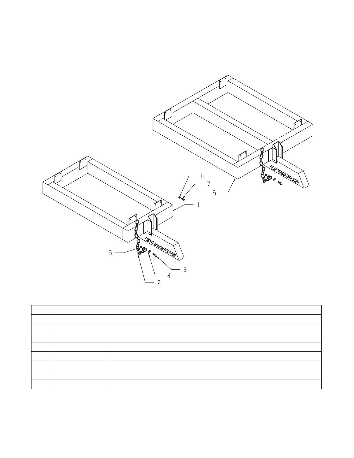
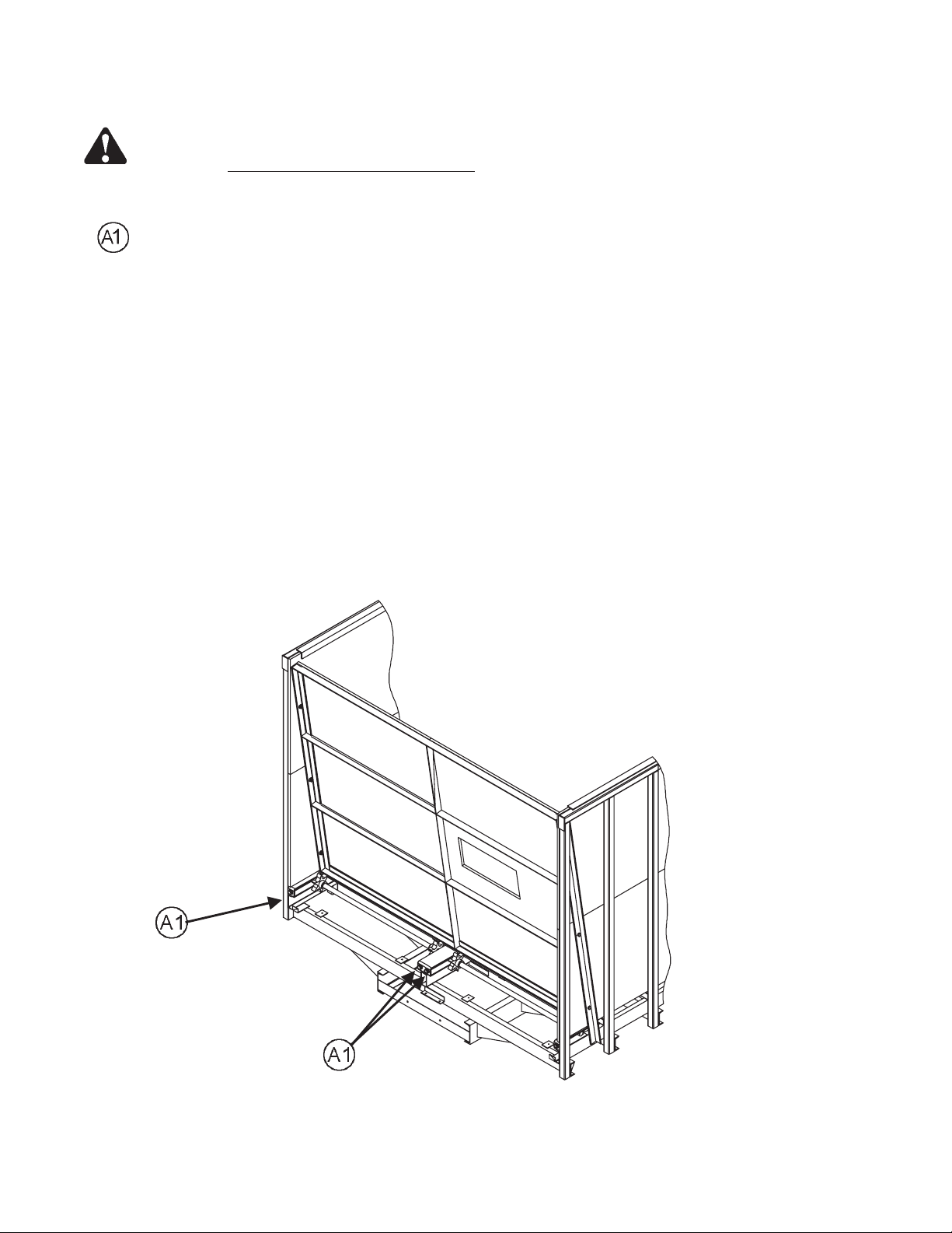
OPTIONAL WAGON MOUNT KIT (#8100 - WAGON)
KEY PART NO. DESCRIPTION
1 25-8025 Wagon Mount Weldment - Front
2 75-0341-4-HD Chain, 61” Long
3 851-3816-1.5Z Bolt, 3/8-16 x 1.5 Hex Head Machine Bolt
4 805-0038-Z Washer, 3/8” Flat
5 814-3816-Z Nut, 3/8-16 Center Lock
6 25-8026 Wagon Mount Weldment - Rear
7 851-5013-1.25Z Bolt, ½-13 x 1.25 Hex Head Machine Bolt
8 815-5013-Z ½-13 Nylon Locknut
--39-- 8100 Rear Unload
Page 41

MEYER FORAGE BOX “MAINTENANCE RECORD”
Model No. ____________________ Serial No. ____________________
Delivery Date: ____________________
DATE SERVICE PERFORMED DATE SERVICE PERFORMED
--40-- 8100 Rear Unload
Page 42

“SPECIFICATIONS”
Truck Mount Models
DIMENSIONS
Inside Length 18' 19'-4" 22' 24'8"
Inside Width 97" 97" 97" 97"
Inside Height 72.5" 72.5" 72.5" 72.5"
Overall Length 18'9" 20'1" 22'9" 25'5"
Overall Width 102" 102" 102" 102"
Overall Height - Tailgate 103" 103" 103" 103"
Overall Side, Height w/6"
Stringers
Weight 6100# 6520# 7120# 7760#
Stringer Width (Truck Mount) 33-1/2" 33-1/2" 33-1/2" 33-1/2"
Capacity (Struck level) cu. ft. 880 978 1075 1200
SPECIFICATIONS
Maximum Net Load 25 ton 25 ton 25 ton 25 ton
Roller Chain Drive - Aprons 80 - 120 80 - 120 80 - 120 80 - 120
Apron Chains (Pintle) 667XH 667XH 667XH 667XH
HP Requirements (Min.) - Truck 50 HP 50 HP 50 HP 50 HP
Rear Drive Shaft - Heavy Duty 2-1/2" Hvy Tubing 2-1/2" Hvy Tubing 2-1/2" Hvy Tubing 2-1/2" Hvy Tubing
Upright Spacing 16" on center 16" on center 16" on center 16" on center
Upright Constructions 2" x 2" Tubing 2" x 2" Tubing 2" x 2" Tubing 2" x 2" Tubing
Power Source (540 RPM) PTO or Hyd. PTO or Hyd. PTO or Hyd. PTO or Hyd.
Unloading Time (PTO) 30 sec. 30 sec. 30 sec. 30 sec.
OPTIONS
All Fiberglass Plywood Sides STD. STD. STD. STD.
All Superslick Floor STD. STD. STD. STD.
Automatic Roller Chain Tighteners STD. STD. STD. STD.
Automatic Rear Door Latching STD. STD. STD. STD.
Front Gate Viewing Window STD. STD. STD. STD.
Semi-Automatic Roller Chain Oiler STD. STD. STD. STD.
Tandem Axle Tire Fenders STD. STD. STD. STD.
Transport ag. Lights STD. STD. STD. STD.
Roll Tarp Cover OPT. OPT. OPT. OPT.
Personalized Farm Name on
Sides
Truck Mount Tie Down Kit/Factory
Mount
8118 8120 8122 8124
REAR UNLOAD
90" 90" 90" 90"
STD. STD. STD. STD.
OPT. OPT. OPT. OPT.
Manufactured by:
Meyer Mfg. Corp.
County Hwy. A West
P.O. Box 405
Dorchester, Wisconsin 54425-0405
Phone 715-654-5132 · FAX 715-654-5513
1-800-325-9103
www.meyermfg.com
E-mail: sales @meyermfg.com
Farm Equipment Buyers Trust the Name Meyer!
--41-- 8100 Rear Unload
Page 43

NOTES
--42-- 8100 Rear Unload
Page 44

A
 Loading...