

Meyer 38160, HD 38160 Owner's Manual
HOTSHOT HD
HOTSHOT HD
HOTSHOT HDHOTSHOT HD
COMMERCIAL BROADCAST SPREADER
MODEL 38160
38160
3816038160
OWNER’S MANUAL
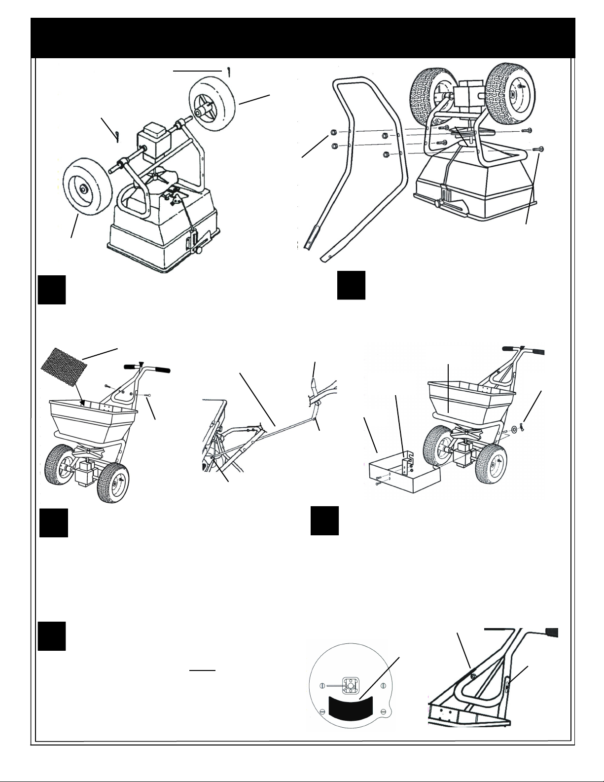
3/16 Dia. x 2”
Cotter Pin
Drive
Wheel
ASSEMBLY
1/8 Dia. x 1 1/4”
Cotter Pin
Free
Wheel
1/4-20 Hex
Lock Nut
1/4-20 x 2 3/4”
Hex Bolts
Remove spreader and components from carton
and place spreader upside down. Slide drive and
1
free wheels on axle as shown with the longer
portion of wheel hub facing the frame. Secure free wheel
with a 1/8 Dia. x 1 1/4” cotter pin. Secure drive wheel to axle
with 3/16” Dia. x 2” cotter pin.
Screen
Control Tube
1/4-20 x 1 1/2”
Carriage Bolts
& Lock Nuts
3/32” Dia.
Cotter Pin
Turn spreader upright on wheels. Insert screen into hopper
3
sliding it under the screen clips. Attach the upper handle
assembly to handle brace with the handle lever facing up
as shown. The holes in the handle brace are slotted and will be
used to adjust for complete shutoff in step #5. Secure with (2)
1/4-20 x 1 1/2” carriage bolts, and locknuts. Install control tube to
handle lever with and a 3/32” dia. cotter pin and clevis pin.
Remove tape holding the lower rod to the pivot lever and slip
opposite end of control tube over lower control rod. Secure with a
3/32” dia. cotter pin.
To check spreader for complete shutoff, pull the on/off
control lever back to the “OFF” position. Determine if the
5
hole in the hopper is completely closed. Also check to make
sure shut off plate is not closing too far which will cause the control
lever to bind. If adjustment is needed, loosen the two carriage
bolts holding the upper handle to the handle brace assembled in
step #3. The holes in the brace are slotted to allow the upper
handle to be moved. Slide the upper handle toward the hopper to
increase the shutoff, move handle in the opposite direction to
reduce shutoff. Re-tighten bolts and recheck shutoff.
Note Position of
Handle Lever
& Clevis Pin
Attach leg/brace to frame inserting the 1/4-20 x
2 3/4” bolts from the inside of the frame as
2
shown. Secure with (4) 1/4-20 lock nuts. NOTE:
Bolts are extra long and will be used for attaching the
ice melt deflector.
Bumper
Bar
Deflector
Bracket
Deflector
3/32” Dia.
Cotter Pin
Install deflector bracket to the inside of deflector as
shown and secure with (2) #10-24 x 1/2” screws and
4
locknuts. Note position of holes in the deflector when
installing the bracket. bolts. Hold the ends of the deflector
open slightly to clear the spreader frame in the back. Hang the
deflector onto the spreader bumper bar. Align the slots in the
back of deflector with the top frame bolts and secure both sides
of the deflector with washers and wing nuts. To remove, simply
loosen the wing nuts, spread the deflector slightly to clear the
frame, and slide the deflector off. Retighten wing bolts.
VIEW INSIDE OF HOPPER
closed in “OFF”
Hole should be
Position
Slotted
Hole
Wing Nut &
Slotted
Washer
Hole
 Loading...