

Meyer BL 240, BL 400, 31100, 36100 Installation Manual
Form No.1-999
May 2010
PARTS & INSTALLATION INSTRUCTIONS
MEYER BL 240 (31100) & BL 400 (36100) SPREADER
PARTS LIST
Item Part No. Qty. Description
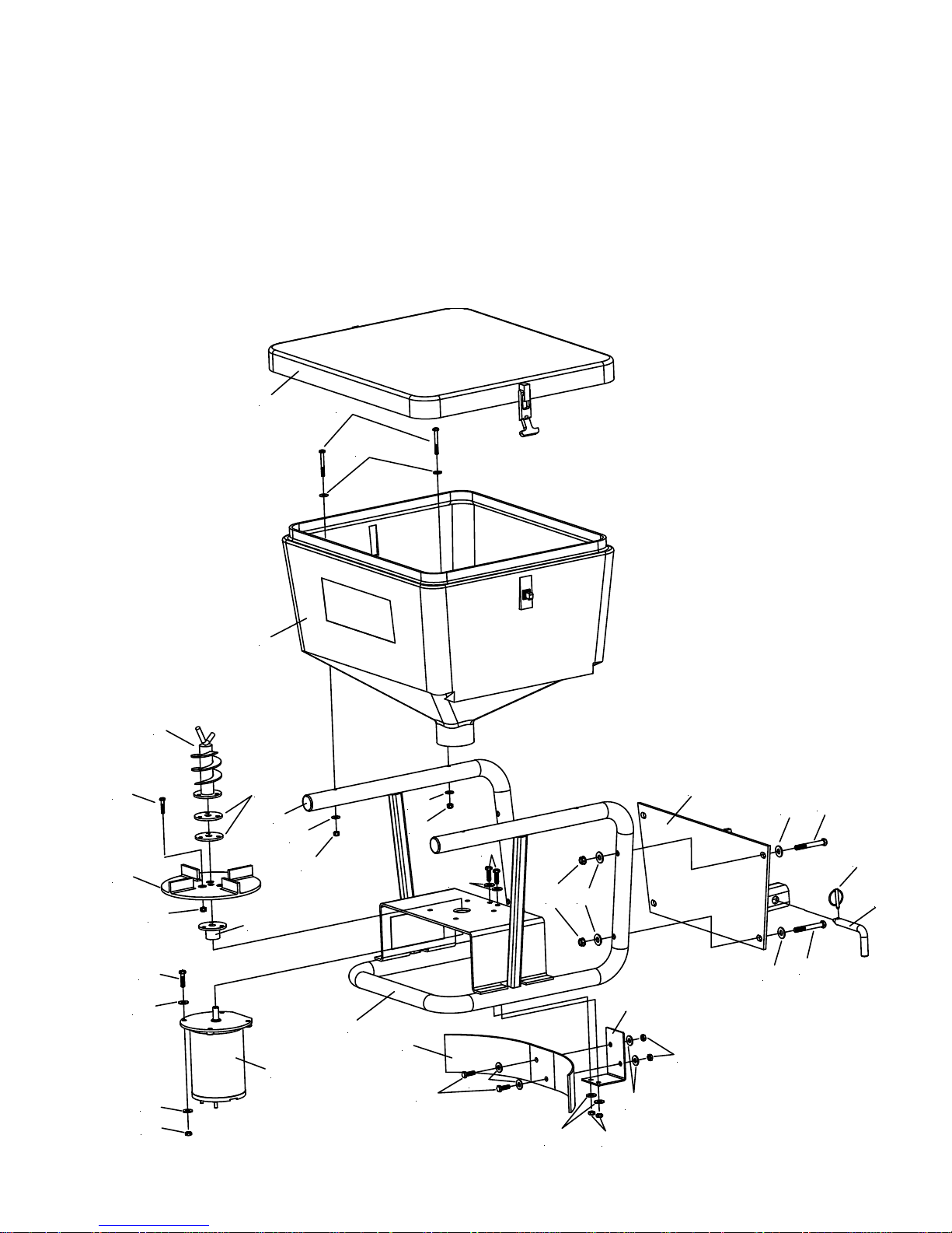
1 31101 1 • 240 Hopper
1 36101 1 • 400 Hopper
2 31102 1 • Hopper Cover
3 34413 1 • 240/400 Spreader Frame
4 34415 1 • Deflector Bracket
5 34401 1 • Deflector
6 34416 2 • Tube Plug
7 36402 1 • Motor 12V D.C.
8 36151 1 • Auger Weldment
9 36152 1 • Spinner Hub Weldment
10 36158 2 • Spinner Mounting Plate
11 36414 1 • Spinner (Poly)
12 34414 1 • 240/400 Hitch Assembly
13 34417 1 • 2 Speed Controller
14 20006 3 • Bolt H 1/4 - 20 x 1-1/4" Gr. 2
15 20010 4 • Bolt H 1/4 - 20 x 2-1/4" Gr. 2
16 20027 4 • Bolt H 5/16 - 18 x 1" Gr. 2
17 20028 4 • Bolt H 5/16 - 18 x 1-1/4" Gr. 2
18 20303 7 • Locknut 1/4 Esna
19 20313 8 • Locknut 5/16 Esna
20 20351 8 • Flatwasher 1/4
21 20352 16 • Flatwasher 5/16
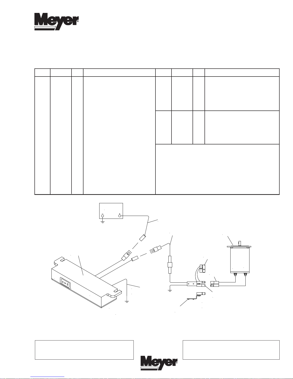
Battery
Item Part No. Qty. Description
08259 1 • 240/400 Hitch Hardware Bag
22 11101 1 •• Hinge Pin
23 20069 4 •• Bolt H 3/8-16 x 3"
24 20314 4 •• Locknut 3/8
25 20353 8 •• Flatwasher 3/8
26 22083 1 •• Linch pin
31103 1 • 240/400 Wiring Kit
27 36240 1 •• Socket Assy. w/Mtg. Plate
28 36241 1 •• Plug Assembly
29 36242 1 •• Wire, Red 222"
30 36247 1 •• Wire, Red 96"
31 36248 1 •• Dummy Plug
• Parts indented are included in carton, bag or assembly
under which they are indented.
30
13
29
31
7
+
-
28
O
L
O
F
F
H
I
S
P
E
C
E
O
D
N
T
R
O
L
Controller must
Figure 1
Meyer Products reserves the right, under its continuing product improvement program, to change construction or design details, specifications
and prices without notice or without incurring any obligation.
Meyer Products LLC
18513 Euclid Ave. • Cleveland, Ohio 44112-1084
Phone 486-1313 (Area Code 216)
www.meyerproducts.com• email info@meyerproducts.com
GROUNDED
BLACK
GROUND WIRE
27
SIDE VIEW OF
SOCKET (27)
27
Meyer Products LLC
6 Angell Lane • Damariscotta, ME 04543-4507
Phone 563-2227(Area Code 207)
www.meyerproducts.com• email info@meyerproducts.com
© 2010 Printed in the U.S.A.
GENERAL INFORMATION
INSTALLATION INSTRUCTIONS
CAUTION: Always disconnect battery before beginning
installation.
Check contents against the parts list to determine all are
correct and included, and also to familiarize yourself with
them.
Locknuts are furnished. DO NOT tighten bolts and nuts
until installation is complete (unless otherwise specified),
then be sure to tighten all attaching parts per specified torque
chart.
When ordering parts, furnish Part No., Name and
Description.
Figure 2
2
15
20
A. Assemble Hitch Assembly (12) to Spreader Frame (3)
using 3/8-16 x 3" Bolt (23), 3/8 Flatwasher (25) and
3/8 Locknut (24).
B. Slide Spreader Assembly into receiver hitch on vehicle
and insert Hinge Pin (22) through corresponding hole
on receiver and Hitch Assembly (12). Secure Hinge
Pin with Linch Pin (26).
C. Tighten all bolts to their required torque using the chart
below.
D. ELECTRICAL INSTALLATION. Refer to Figure 1.
14
11
17
21
21
19
18
1
8
10
6
20
18
16
18
20
12
25
23
26
21
24
25
22
9
23
25
4
3
5
7
16
21
21
21
19
19
Meyer Products assumes no responsibility for installations not made in accordance with these instructions.
 Loading...