


Page
1 / 43
Documentation
DPM
Operating manual for precision cutting machine
Approved on: 23/02/2017 Approved by: M. Kieble
(Changes reserved!)
Approval no. 300.00.00550
Operating Manual
GMT 6000 - Precision cutting machine

Page
2 / 43
Documentation
DPM
Operating manual for precision cutting machine
Approved on: 23/02/2017 Approved by: M. Kieble
Preface
The information contained in this manual ensures that the dpm ejector
cutting unit is operated safely, properly and efficiently. Following the
explanations, notices and regulations:
prevents hazards and faults,
reduces repair costs and downtimes
increases reliability and the service life
of the machine. The operator must ensure that persons tasked with
using, maintaining and repairing the dpm ejector cutting unit read the
manual. The manual must be kept at hand in the place where the
machine is used.
Not being familiar with or not observing this manual can give rise
to hazards to persons!
This manual must be read carefully before the ejector cutting unit
is commissioned. The instructions, particularly the safety
instructions, must be followed!
This manual applies only to the "ejector cutting unit“ indicated on the
cover page and specified in the section on "Suitability". Before it is used
outside its described field of application, it is essential to consult
dpm Daum + Partner Maschinenbau GmbH
Am Lauerbühl 2
D - 88317 Aichstetten, Germany
Tel. +49 7565 94080 Fax. +49 7565 940850
Otherwise any warranty, liability and accessory liability claims shall be
void.
Copyright © 13 April 2017 10:00:43 by dpm Daum + Partner
Maschinenbau GmbH Realisation: dpm Daum + Partner Maschinenbau
GmbH
All rights to this manual are reserved, particularly the right of
reproduction and distribution as well as translation. No part of the
manual may be reproduced or electronically processed, copied or
distributed in any form (by copying, on microfilm or by another means)
without the prior written permission of Daum + Partner.
Issue: 13 April 2017 10:00:43 Author: M. Kieble/EW

Page
3 / 43
Documentation
DPM
Operating manual for precision cutting machine
Approved on: 23/02/2017 Approved by: M. Kieble
Contents
Preface ................................................................................................................................................. 2
Contents ............................................................................................................................................. 3
1. Notes about the operating manual ............................................................................................ 5
1.1 Note, terms, symbols .............................................................................................................. 5
1.2 Pictograms ............................................................................................................................ 6
2. Correct use in accordance to the instructions (intended use) ................................................ 7
2.1 Use of the machine ................................................................................................................ 7
3. Safety .......................................................................................................................................... 8
3.1 Safety directives and regulations ............................................................................................ 8
3.2 Safety hazards ....................................................................................................................... 8
3.3 Safety symbols and safety markings of the ejector cutting unit .............................................. 10
4. Overall view .............................................................................................................................. 11
4.1 Complete control unit .......................................................................................................... 13
4.2 Complete linear unit ............................................................................................................ 14
4.3 Clamping prism .................................................................................................................. 15
4.4 Support prism ..................................................................................................................... 16
4.5 Length adjustment .............................................................................................................. 17
4.6 Pivoting motor base ............................................................................................................. 18
4.7 Grinding spindle / cutting wheel ........................................................................................... 20
4.8 Grinding spindle / cup wheel ................................................................................................ 21
4.9 Rocker bearing .................................................................................................................... 22
4.10 Spindle bearing ................................................................................................................... 23
4.11 Technical Data .................................................................................................................... 24
5. Operation .................................................................................................................................. 25
5.1 Setting up the machine: ....................................................................................................... 25
5.2 Machine connections: .......................................................................................................... 26
5.3 Controls and displays .......................................................................................................... 27
5.4 Switching on ....................................................................................................................... 30
5.5 Switching off ....................................................................................................................... 30
5.6 Dressing the grinding wheel ................................................................................................. 30
5.7 Inserting a workpiece .......................................................................................................... 30
5.8 Referencing "obtaining zero position".................................................................................. 31
5.9 Cut-off grinding .................................................................................................................. 31

Page
4 / 43
Documentation
DPM
Operating manual for precision cutting machine
Approved on: 23/02/2017 Approved by: M. Kieble
5.10 Surface grinding .................................................................................................................. 31
5.11 Emergency stop ................................................................................................................... 32
5.12 Acknowledge the emergency stop ......................................................................................... 32
6. Care and maintenance ............................................................................................................. 33
7. Spare parts list ......................................................................................................................... 38
8. Accessories .............................................................................................................................. 40
9. Declaration of Conformity ....................................................................................................... 42
Fault report fax ................................................................................................................................. 43

Page
5 / 43
Documentation
DPM
Operating manual for precision cutting machine
Approved on: 23/02/2017 Approved by: M. Kieble
1. Notes about the operating manual
1.1 Note, terms, symbols
Safety Safety regulations for safe, risk-free use of the ejector cutting unit.
Operation Information about the suitability, use, function, operation, variants
and accessories.
Commissioning Information on the operation of the machine
Control Explanation of the control elements, description of handling.
Maintenance Work that must be done for the purpose of safe operation, to
maintain functional capability and to avoid hazards or faults.
Faults Explanation of the causes of faults and how to remedy them.
Appendix Illustrations, standard maintenance instruction, sample of an
inspection report in accordance with the directives of the
employer's liability insurance association.

Page
6 / 43
Documentation
DPM
Operating manual for precision cutting machine
Approved on: 23/02/2017 Approved by: M. Kieble
1.2 Pictograms
The machine and this manual carry labels that warn of hazards,
stipulate or command particular actions and point out special
information. It is essential to follow the notices and regulations that
these highlight!
Danger!
Warning about a dangerous situation. There is a direct risk of a serious
accident is the regulations and instructions are not observed!
Warning!
Warning about a possibly dangerous situation! Not following the instruction
can give rise to accident risks!
Caution!
Warning about a possibly dangerous situation or damage. Not following
the instructions can give rise to accident risks or damage to the ejector
cutting unit.
Command!
A particular action is stipulated! Not following the command can give rise
to a dangerous situation or damage!

Page
7 / 43
Documentation
DPM
Operating manual for precision cutting machine
Approved on: 23/02/2017 Approved by: M. Kieble
Note!
Supplementary information about particular circumstances, explanations,
descriptions, cross references, explanations of special activities or
functional processes. Not following the instruction can give rise to
damage. There is no accident risk.
2. Correct use in accordance to the instructions (intended use)
2.1 Use of the machine
Machine tool for cutting and surface grinding of cylindrical and stepped ejector pins, flat ejectors,
profile stamps, punching dies, ejector bushes etc. The grinding wheels are driven by two three-phase
asynchronous motors with squirrel-cage rotors by a toothed belt drive. The force exerted by the
workpiece on the grinding wheel is always radial. The cup wheel can be aligned by a puller diamond
and set with an adjusting screw until the wear limit is reached. The workpiece is held in place by a
spring clamping prism and positioned with a stop. A linear unit with screw spindle adjustment and
visual digital output facilitates the exact (0.01 mm) positioning/advance of the workpiece before
cutting (separation) and subsequent surface grinding.

Page
8 / 43
Documentation
DPM
Operating manual for precision cutting machine
Approved on: 23/02/2017 Approved by: M. Kieble
3. Safety
3.1 Safety directives and regulations
The following general safety regulations must be followed:
Commissioning, operation and maintenance only after briefing and
instruction by the owner and knowledge of the operating manual.
Commissioning, operation and maintenance only by trained and
qualified personnel (protective goggles and safety shoes are
mandatory)
When switching on the machine, the direction of rotation of the cup
wheel must be clockwise and that of the cutting wheel must be counterclockwise, see also instructions under 5.2 Connections of the machine
Only switch on once you have checked the safety devices function
correctly.
Do not tamper with any safety devices or bypass, deactivate or
remove them.
The accident prevention regulations must be observed, and all working
methods that can jeopardise work safety are prohibited.
3.2 Safety hazards
Potential hazards if the operating manual is not followed:

Page
9 / 43
Documentation
DPM
Operating manual for precision cutting machine
Approved on: 23/02/2017 Approved by: M. Kieble
If the machine is not operated, maintained or repaired in accordance
with the safety regulations, or if it is operated improperly or misused, the
result is
• Hazards to the health of operating personnel,
• Hazards to the machineand other property belonging to the operator
• Impairment of the machine's efficient functioning.
If the regulations laid down in the operating manual are not observed, the
manufacturers shall not be liable for the resulting damage and consequential
losses!
Safety hazards can occur from:
• Working at the machine without a protective cover on the grinding wheel,
(unauthorized changes to the safety devices are not permitted).
• The two grinding wheels rotating in the incorrect direction
• The rotating grinding wheels when working at the machine (there is a risk of
clothes, long hair or gloves being pulled into the machine).
• Force applied to the grinding wheels in the axial direction. (There is a risk of
breakage of the grinding wheels).
• Operating the rocker mechanism (there is a risk of crushing between the
rocker and its base).
• Working on the machine without protective goggles (danger from flying metal
chips and grinding dust).
• Removing the cut-off workpiece parts (risk of burning)
• Parts can be thrown out if the grinding wheels are defective. (risk of injury).
• Inserting the shaft into the spring prism (risk of crushing fingers).
• Risk from electrostatic charging of components, personnel touching contact
charged parts.
• Working at the electronic box or motor housing by touching live parts during
operation. Risk from damaged lines or cables. Only trained electricians may
carry out such work.
• Do not operate the machine in hazardous areas.
• Switching on the machine with the workpiece inserted

Page
10 / 43
Documentation
DPM
Operating manual for precision cutting machine
Approved on: 23/02/2017 Approved by: M. Kieble
• Transportation of the machine - personal safety measures appropriate to the
total weight of the machine must be taken. Additionally, the personnel must
be informed about any loose or moving parts of the machine before
transport. (Only trained and instructed personnel are permitted to transport
the machine).
• The main switch must be switched off for maintenance, inspection or
cleaning of the machine.
3.3 Safety symbols and safety markings of the ejector cutting unit
1
Mandatory
instruction
Disconnect first, then work on the electrical
installation.
2
Mandatory
instruction
Wear ear protection
3
Mandatory
instruction
Wear protective goggles!
4
Mandatory
instruction
First read the operating manual, then activate!
5
Warning
There is the risk of crushing at the clamping device
of the shaft and the rocker mechanism
6
Warning
There is a risk of electric shock

Page
11 / 43
Documentation
DPM
Operating manual for precision cutting machine
Approved on: 23/02/2017 Approved by: M. Kieble
4. Overall view
1) 300.00.00398 (1x)
Base
5) 060.30.905 (1x)
Glass scale MKT 37
9) 300.00.00392 (1x)
Disc cover
13) 050.01.2971
Cup wheel
2) 300.00.00370 (1x)
Complete control cabinet
6) 300.00.00174 (1x)
Longitudinal adjustment (cup
wheel)
10) 300.00.00392 (1x)
Disc cover
14) 050.01.2972
Cutting wheel
3) 300.00.00403 (1x)
Linear unit
7) 050.01.2744 (1x)
Handle
11) 300.00.00387 (1x)
Holding rail for handle
4) 300.00.00462 (1x)
Cover
8) 300.00.00390 (1x)
Cover for complete grinding
wheel
12) 050.01.2953
Insulation for cover
2
7/11
6
3
1
9
8
4/12
5
10 13
14

Page
12 / 43
Documentation
DPM
Operating manual for precision cutting machine
Approved on: 23/02/2017 Approved by: M. Kieble
15) 050.01.2750 (1x)
Corrugated pipe fitting 90°
19) 300.00.00433 (1x)
Complete drive console
23) 300.00.00437 (2x)
Bracket
16) 050.01.2886 (4x)
Rubber-metal stop
20) 300.00.00452 (1x)
Spring retainer, long
24) 300.00.00451 (1x)
Spring retainer, short
17) 300.00.00359 (1x)
Adjustable spindle mount
21) 050.01.2928 (2x)
Pressure spring
25) 300.00.00372 (2x)
Adjusting block
18) 060.80.279 (1x)
Counter nut M32x1.5
22) 300.00.00436 (2x)
Spring bearing
15/18
16
19
17
20/21/22/23
24 25

Page
13 / 43
Documentation
DPM
Operating manual for precision cutting machine
Approved on: 23/02/2017 Approved by: M. Kieble
4.1 Complete control unit
1) 300.00.00355 (1x)
Bottom cover
9) 300.00.00360 (1x)
Control cabinet housing
17) 060.80.008-200 (1x)
DIN rail 35x7.5
25) 060.72.622 (2x)
End clamp TS 35
2) 300.00.00367 (1x)
Electrics box cover
10) 060.08.351 (1x)
Mounting case, angled
18) 060.40.2812 (1x)
3-pin circuit breaker
26) 060.72.605 (2x)
4-wire circuit terminal
2.5mm²
3) 050.01.2750 (1x)
Corrugated pipe fitting 90°
11) 060.02.588 (1x)
Emergency stop mushroom
pushbutton
19) 060.07.009 (1x)
Safety relay
27) 060.72.606 (2x)
Baffle plate, grey
4) 060.07.005 (3x)
Illuminated toggle switch,
green
12) 060.30.904 (1x)
Innova display
20) 060.07.015 (3x)
Sirius motor starter
28) 060.72.604 (2x)
4-wire circuit terminal
2.5mm², grey
5) 060.80.29501 (1x)
Cable gland
13) 300.00.00368 (1x)
El. box cover
21) 060.40.252 (1x)
1-pin circuit breaker
29) 060.72.623 (1x)
Group tag holder
6) 060.08.716 (1x)
CEE plug
14) 060.07.012 (1x)
Main / emergency-stop switch
22) 300.00.00426 (1x)
Operating panel, angled
7) 050.01.2751 (1x)
Corrugated pipe PUR NW 29
15) 060.07.006 (1x)
Illuminated pushbutton, blue
23) 060.80.29521 (1x)
10mm cable grommet
8) 060.04.031 (4x)
Tag labelling
16) 060.80.279 (1x)
Counter nut M32x1.5
24) 060.07.016 (1x)
3-phase busbar
2/
13
12
3/
7/
16
18
19 20
25/
26/
27/
28/
29
15
11
14
4
8
1
10
6
5/
23
9
22
17
24
23

Page
14 / 43
Documentation
DPM
Operating manual for precision cutting machine
Approved on: 23/02/2017 Approved by: M. Kieble
4.2 Complete linear unit
1) 300.00.00382 (1x)
Clamping prism
7) 050.01.2713 (1x)
Clamping lever
13) 050.01.2718 (4x)
Ball lining Ø16
2) 300.00.00401 (1x)
Support prism
8) 300.00.00379 (1x)
Carriage guide bracket, outer
part
14) 050.01.2715 (1x)
Hardened precision shaft
Ø12h6
3) 300.00.00173 (1x)
Carriage base
9) 300.00.00174 (1x)
Length adjustment
15) 050.01.2716 (1x)
Hardened precision shaft
Ø8h6
4) 300.00.00386 (1x)
Monitoring car holder
10) 300.00.00466 (1x)
Shaft for length adjustment
16) Threaded pin (1x)
ISO 4026-M6x16
5) 300.00.00166 (1x)
Carriage face plate
11) 300.00.00009 (1x)
Carriage guide bracket, inner
part
17) Hardened cylinder pin (1x)
ISO 8734-8x50
6) 300.00.0456 (1x)
Stop part
12) 050.01.2714 (2x)
Hardened precision shaft
Ø16h6
18) Threaded pin (6x)
ISO 4026-M6x8
5
2
9
15
8 10
11
14 12
1
3
6
16
17
18
7
4
13
Page
15 / 43
Documentation
DPM
Operating manual for precision cutting machine
Approved on: 23/02/2017 Approved by: M. Kieble
4.3 Clamping prism
1) 300.00.00380 (1x)
Clamping prism base plate
5) 050.01.2770 (1x)
Dressing diamond
9) Hardened cylinder pin (2x)
ISO 8734-5x24
2) 300.00.00162 (1x)
Push-pull device guide
6) 050.01.2712 (1x)
Cone handle
10) Hardened cylinder pin (1x)
ISO 8734-5x10
3) 300.00.00161 (1x)
Push-pull device
7) 300.00.00036 (1x)
Lever
11) Threaded pin (2x)
ISO 4026-M5x16
4) 300.00.00163 (1x)
Support
8) 050.01.2892 (1x)
Control spring Ø10x35.3xØ1.4
7
9
11
8
1
2 3 4
5
6
10

Page
16 / 43
Documentation
DPM
Operating manual for precision cutting machine
Approved on: 23/02/2017 Approved by: M. Kieble
4.4 Support prism
1) 300.00.00402 (1x)
Support prism plate
3) Hardened cylinder pin (1x)
ISO 8734-6x20
2) 050.01.2718 (2x)
Bushing
3
2
1

Page
17 / 43
Documentation
DPM
Operating manual for precision cutting machine
Approved on: 23/02/2017 Approved by: M. Kieble
4.5 Length adjustment
1
1) 300.00.00175 (1x)
Adjustment bush
5) Retaining ring (1x)
DIN 471 - 15x1
9) Retaining ring (1x)
DIN 472 - 15x1
2) 300.00.00011 (1x)
Support
6) Axial deep groove ball bearings
(2x)
050.31.910 (Ø15 x Ø28 x 9)
10) 050.01.2717 (1x)
Stopper
3) 300.00.00014 (1x)
Washer disc
7) 050.01.2899 adjusting washer
(1x)
Ø15 x Ø28 x 1
4) 300.00.00396 (1X)
Washer
8) Threaded pin (3x)
ISO 4026-M4x4
3
5
6
7
2
4
9
10
8
For cup wheel
adjustment

Page
18 / 43
Documentation
DPM
Operating manual for precision cutting machine
Approved on: 23/02/2017 Approved by: M. Kieble
4.6 Pivoting motor base
1) 300.00.00409 (1x)
Cutting wheel grinding spindle
7) 300.00.00194 (1x)
Belt wheel T5/Z72
13) 300.00.00352 (1x)
Adjustment bracket
2) 300.00.00407 (1x)
Cup wheel grinding spindle
8) 300.00.00186 (1x)
Belt wheel T5/Z48
14) 300.00.00412 (1x)
Stop ring
3) 060.07.051 (1x)
Three-phase asynchronous
motor
0.75 kW
9) 300.00.00427 (1x)
Mounting flange for motor,
small
15) 300.00.00423 (1x)
Perforated sheet
4) 060.07.050 (1x)
Three-phase asynchronous
motor
0.37 kW
10) 300.00.00428 (1x)
Mounting flange for motor,
large
16) 300.00.00063 (1x)
Positioning/advance holder
5) 050.01.2747 (1x)
Toothed belt T5 Z78
11) 300.00.00195 (1x)
Connection plate
17) 300.00.00235 (1x)
Motor cover
6) 050.01.2746 (1x)
Toothed belt T5 Z90
12) 300.00.00187 (1x)
Connection plate
18) 050.01.2748 (2x)
Scraper Ø40xØ48.6x7
19) 300.00.00094 (1x)
Pressure spring Ø14 x 1 x 160
14
2
3
5
6
7
9
10
12
11
13
8
4
1
15
16
17

Page
19 / 43
Documentation
DPM
Operating manual for precision cutting machine
Approved on: 23/02/2017 Approved by: M. Kieble
Info! M6 bolts glued with VBA 2M70 (Meusburger)!
19
18

Page
20 / 43
Documentation
DPM
Operating manual for precision cutting machine
Approved on: 23/02/2017 Approved by: M. Kieble
4.7 Grinding spindle / cutting wheel
1) 300.00.00408 (1x)
Grinding spindle sleeve
5) 300.00.00050 (1x)
Disc flange, inside
9) 300.00.00052 (1x)
Threaded ring
2) 300.00.00048 (1x)
Grinding spindle shaft
6) 300.00.00055 (1x)
Washer
10) 300.00.00182 (1x)
Toothed belt pulley T5 Z19
3) 300.00.00053 (1x)
Spacer sleeve
7) Fitting key (1x)
DIN 6885 A4x4x18
11) Cylinder head bolt
ISO 4762 M6x16-12.9 (1x)
4) 300.00.00393 (1x)
Clamping nut
8) 050.31.015 (2x) deep groove
ball bearings
DIN 625 SKF 6001-2RS1
10
1
2
9
5
4
6 7 8 3
11

Page
21 / 43
Documentation
DPM
Operating manual for precision cutting machine
Approved on: 23/02/2017 Approved by: M. Kieble
4.8 Grinding spindle / cup wheel
1) 300.00.00045 (1x)
Grinding spindle sleeve
5) 300.00.00223 (1x)
Disc flange inside, left-hand
thread
9) Fitting key (1x)
DIN 6885 A4x4x18
13) Hardened cylinder pin (1x)
ISO 8734-5x16
2) 300.00.00406 (1x)
Grinding spindle shaft
6) 300.00.00394 (1x)
Clamping nut, left-hand thread
10) 050.31.015 (2x)
Deep groove ball bearings DIN
625 SKF 6001-2RS1
14) 050.01.2887 (1x)
ISO 4762 M6x16-12.9 (left-hand
thread)
3) 300.00.00061 (1x)
Adjusting support
7) 300.00.00052 (1x)
Threaded ring
11) 300.00.00185 (1x)
Toothed belt pulley T5 Z30
4) 300.00.00468 (1x)
Cup wheel adjustment shaft
8) 300.00.00055 (1x)
Washer
12) Threaded pin (1x)
ISO 4026-M6x10
1
2
7
5
3
11
9
8
4
12
10
6
13
14

Page
22 / 43
Documentation
DPM
Operating manual for precision cutting machine
Approved on: 23/02/2017 Approved by: M. Kieble
4.9 Rocker bearing
1) 300.00.00359 (1x)
Spindle bearing
4) 300.00.00454 (1x)
Cover sheet
7) Cylinder pin (1x) (pivot)
ISO 8735-16x32
2) 300.00.00146 (2x)
Washer
5) 050.31.911 (2x)
Tapered roller bearing DIN 720
SKF 32004X
3) 300.00.00004 (2x)
Rubber ring Ø3 5x2 0x3
6) 050.01.3010 (1x)
Slotted nut DIN 981 KM 4
4
1
3
2
6
7
5

Page
23 / 43
Documentation
DPM
Operating manual for precision cutting machine
Approved on: 23/02/2017 Approved by: M. Kieble
4.10 Spindle bearing
1) 300.00.00357 (1x)
Base holder
4) Cylinder pin (2x)
ISO 8735-6x30
7) 050.01.2896 / DIN 961
Hex bolt M8x1 x 35
2) 300.00.00358 (1x)
Top section holder
5) Cylinder pin (1x)
ISO 8734-8x30
8) 050.01.2897 / DIN 934
Hex nut M8x1
3) 300.00.00371 (1x)
Rocker shaft
6) Cylinder pin (1x)
ISO 8735-16x40 (pivot)
6
4
7
1
2
3
5
8

Page
24 / 43
Documentation
DPM
Operating manual for precision cutting machine
Approved on: 23/02/2017 Approved by: M. Kieble
4.11 Technical Data
Weight 120 kg
Dimensions (L x W x H) 970 x 540 x 520 mm
Electrical connection 2x 400 V
Motor power, cutting 0.75 kW
Motor power, grinding 0.37 kW
Cutting wheel speed 10700 rpm
Cup wheel speed 4400 rpm
Cutting wheel Ø 100/20x1 mm
Cup wheel Ø 100/20x50 mm
Grinding range Ø 1-20 mm
Stop Ø ejector head ≥ 3mm
Workpiece length, direct reading 370 mm
Max. workpiece length 460 mm

Page
25 / 43
Documentation
DPM
Operating manual for precision cutting machine
Approved on: 23/02/2017 Approved by: M. Kieble
5. Operation
5.1 Setting up the machine:
(1) Device foot
• Place the machine on a level surface (e.g., substructure GMT 60002 or
work bench).
• Make sure that the machine is only standing on its four legs.
• Allow sufficient space in the front and rear of the machine to ensure the
rocker mechanism is not blocked.
1

Page
26 / 43
Documentation
DPM
Operating manual for precision cutting machine
Approved on: 23/02/2017 Approved by: M. Kieble
5.2 Machine connections:
Note!
When you first turn on the machine, make sure the grinding wheel has the
correct direction of rotation. If this does not correspond to the direction
shown above, the rotating field must be changed by turning the phase
inverter at the Cekon plug. Caution: This may only be done by trained
electricians!
Cekon plug
400V/16A 50Hz with
phase inverter
3A mounting case
230V/16A 50Hz for
coolant pump
Threaded connection G
¼“ for coolant supply

Page
27 / 43
Documentation
DPM
Operating manual for precision cutting machine
Approved on: 23/02/2017 Approved by: M. Kieble
5.3 Controls and displays
The machine has the following controls and displays:
(1) Digital display preset to
1
/
100
- millimetre division
(2) Control for setting and configuring the display - please observe separate
instructions from the Fagor company
(3) Cutting wheel on/off toggle switch
(4) Acknowledge emergency stop illuminated pushbutton
(5) Surface grinding machine (cup wheel) on/off toggle switch
(6) Emergency stop mushroom pushbutton
(7) Coolant pump on/off toggle switch (only for wet grinding unit)
(8) Main switch
3
7
1
5
4
6
8
2

Page
28 / 43
Documentation
DPM
Operating manual for precision cutting machine
Approved on: 23/02/2017 Approved by: M. Kieble
(9) Adjusting screw for dressing the cup wheel
Caution! Set only when the motor is running, otherwise the belt breaks!
(10) Rocker mechanism
Dressing
9 10

Page
29 / 43
Documentation
DPM
Operating manual for precision cutting machine
Approved on: 23/02/2017 Approved by: M. Kieble
(11) Workpiece clamping lever
(12) Clamping prism
(13) Support prism
(14) Stop shaft
(15) Fixing screw for the stop shaft
(16) Carriage
(17) Clamping lever for carriage
(18) Fine adjustment for carriage
11
15
17
14 18 16
12
13

Page
30 / 43
Documentation
DPM
Operating manual for precision cutting machine
Approved on: 23/02/2017 Approved by: M. Kieble
5.4 Switching on
(1) Connect the machine to the 400V/AC power supply
(2) Turn main switch (8) to position "I"
(3) Enable the drives by pressing the illuminated pushbutton (4). When the
drives are enabled it lights up blue
(4) Turn toggle switch to the right for cut-off grinding and/or surface grinding
(3)/(5). The toggle switch is lit green during activation.
→ The workpiece must not be inserted!
5.5 Switching off
(1) Turn toggle switch to the left for cut-off grinding and/or surface grinding
(3)/(5). The green light in the toggle switch goes out.
Caution: The discs continue to run for approx. 5 secs.
(2) Turn main switch (8) to position "O"
5.6 Dressing the grinding wheel
(1) Switch on the grinding spindle (see 5.4)
(2) Move the grinding wheel in front of the dressing diamond by pressing and
pulling on the handle of the rocker mechanism (10).
(3) Position the grinding wheel at the dressing diamond by rotating the
adjusting screw (9)
(4) Repeat the rocking motion and the positioning until the grinding wheel is
cleanly disconnected.
5.7 Inserting a workpiece
(1) When machining Ø1mm-Ø20mm, first start the cutting wheel or the cup
wheel before the workpiece is inserted because the rocker mechanism
oscillates place and therefore the inserted part can collide with the
grinding wheels.
(2) Press down the clamping lever (11). The push-pull device pushes itself
upward.
(3) With the clamping lever pressed, place the workpiece through the
mounting hole in the push-pull device onto the support prism (12).
(4) Guide the clamping lever (11) downwards until the workpiece is held by
the push-pull device.

Page
31 / 43
Documentation
DPM
Operating manual for precision cutting machine
Approved on: 23/02/2017 Approved by: M. Kieble
5.8 Referencing "obtaining zero position"
(1) Switch on the grinding wheel (see 5.4)
(2) Release the carriage clamp with the clamping lever (17).
(3) Adjust the stop shaft (14) by releasing the two fixing screws (15) on the
prism.
(4) Push the stop shaft with carriage (16) to just (approx. 1 mm) before the
grinding wheel and fix with the clamping lever (17).
(5) Move the grinding wheel in front of the stop shaft (14) by pressing and
pulling on the handle of the rocker mechanism (10).
(6) Using the fine adjustment (18), place the stop shaft on the grinding
wheel and slightly "scratch" it.
(7) Digital display "Reference", see manual from Fagor, Chapter 2.3
(8) Release the clamping lever (17) on the carriage and move it freely
toward the rear until the clamping mechanism is free to accept a
workpiece.
(9) Insert the workpiece (see 5.7)
(10) With the stop shaft on the carriage (16), push the workpiece shortly
before the desired cutting size (approx. 0.5mm). To do this, keep the
push-pull device open by pressing the clamping lever (11).
(11) Fix the clamping lever for the carriage (17) and set the carriage to the
required cutting size using the fine adjustment (18).
5.9 Cut-off grinding
(1) Switch on the cutting wheel (see 5.4)
(2) Obtain zero (reference) (see 5.8)
(3) By pulling the rocker mechanism, attach the cutting wheel to the
workpiece and draw it through quickly.
Please note:
The workpiece is now approximately 0.1-0.3mm longer than shown on the
digital display
5.10 Surface grinding
(1) Switch on the grinding wheel (see 5.4)
(2) Press the rocker mechanism to move the grinding wheel over the
workpiece and overtighten 3-4 times until there are almost no more flying
sparks.
(3) Switch off the grinding wheel(s) (see 5.5/(1)) and remove the workpiece.

Page
32 / 43
Documentation
DPM
Operating manual for precision cutting machine
Approved on: 23/02/2017 Approved by: M. Kieble
5.11 Emergency stop
(1) The emergency stop (6) can be pressed at any time and switches off the
power to the drives.
(2) The green lights of the toggle switch (3)/(5) of the grinding wheels and the
blue lights on the illuminated pushbutton (4) go out.
Caution: The grinding wheels continue to run for approx. 5 secs.
5.12 Acknowledge the emergency stop
(1) Before re-commissioning after an emergency stop, the operator must
ensure that the cause for the emergency stop has been eliminated in full!
(2) Unlock the emergency-stop mushroom pushbutton by turning it
clockwise.
(3) Turn the toggle switch (3)/(5)/(7) to the left (only for wet grinding unit)
(4) Enable the drives by pressing the illuminated pushbutton (4). When the
drives are enabled it lights up blue The machine is now ready for
operation again

Page
33 / 43
Documentation
DPM
Operating manual for precision cutting machine
Approved on: 23/02/2017 Approved by: M. Kieble
6. Care and maintenance
Maintenance, repair and troubleshooting measures:
• The ejector cutting unit should be regularly serviced and cleaned by a
skilled expert.
• The machine bearings are permanently lubricated and do not require
any maintenance.
• It is strictly prohibited to blow out the machine with compressed air
because the sanding dust may settle in the mechanisms.
• The carriage guide and the support prism must only be cleaned using
a dry cloth.
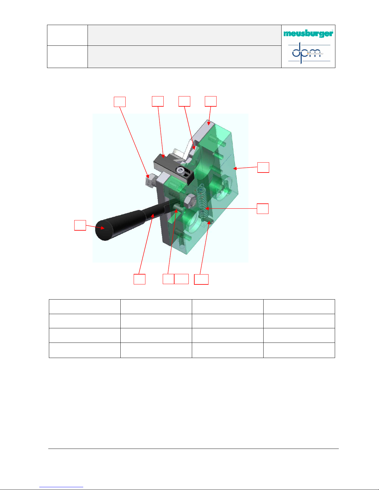
The length adjustment and the cup wheel adjustment
should be oiled semi-annually.
The retaining ring and the washer are removed for this,
and the thread is oiled with VLS 250 (Meusburger). Then
the washer and the retaining ring are re-inserted.
Adjustment
Caution: Only adj
ust the cup wheel when the motor is
running, otherwise the belt will break!
Page
34 / 43
Documentation
DPM
Operating manual for precision cutting machine
Approved on: 23/02/2017 Approved by: M. Kieble
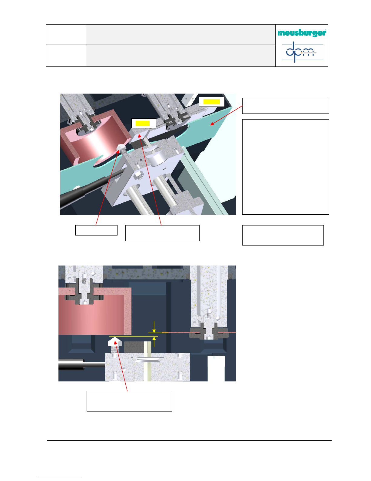
Caution! Only work with the emergency stop actuated!
To set the dressing diamond to the
desired position relative to the cutting
wheel, the adjustment plate (optional)
is screwed on to the spindle instead of
the cutting wheel. The possible
adjustment size is 0.1mm or 0.15mm
to the cutting wheel. The adjustment
plate should be mounted accordingly.
Now, using the rocker function, the
adjustment plate is drawn to the
dressing diamond and this is screwed
on and then secured with the tip up to
the set surface. Caution! After the
adjustment is made, the cutting
wheel and the disc cover must be
re-mounted!
Diamond setting for dressing the cup wheel (with adjustment plate)
Dressing
300.00.00411 Adjustment plate
for dressing diamond (optional)
0.1mm
0.15mm
Disassemble the right disc cover!
Diamond setting for dressing the cup wheel (without adjustment plate)
Approx.
0.1mm
Place the dressing diamond
approx.0.1mm before the cutting
wheel
Caution: Only adjust the cup
wheel when the motor is running,
otherwise the belt will break!
Page
35 / 43
Documentation
DPM
Operating manual for precision cutting machine
Approved on: 23/02/2017 Approved by: M. Kieble
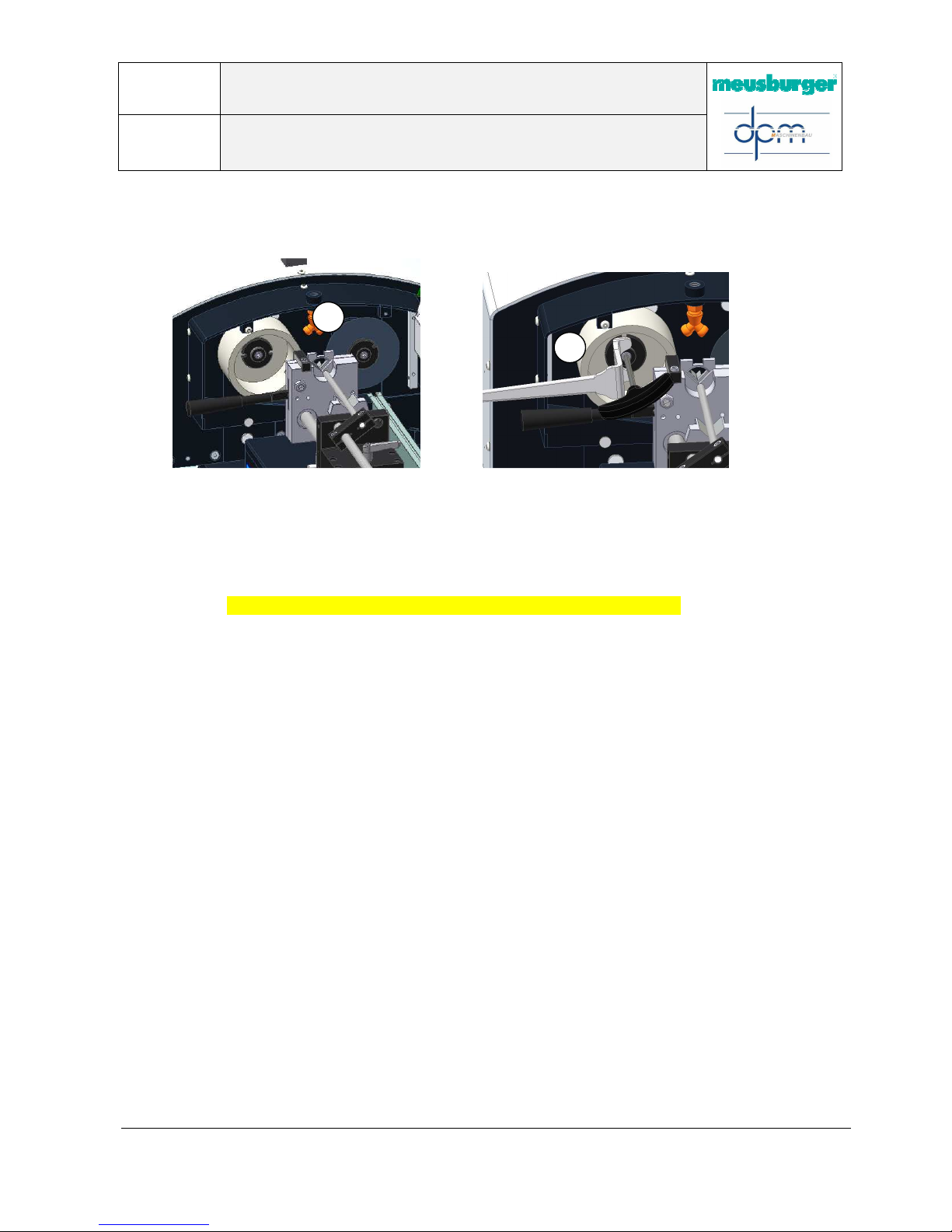
Replacing the grinding wheel (cutting wheel/cup wheel)
Function:
(Fig. 1) Disassemble the front covers.
(Fig. 2) Hold the hex key sw5 and loosen the 2-punched disk with its corresponding angled key
to replace the grinding wheels.
(cup wheel - left-hand thread / cutting wheel - right hand thread) The covers must then
be re-mounted!
Caution! Only work with the emergency stop actuated!
1
2

Page
36 / 43
Documentation
DPM
Operating manual for precision cutting machine
Approved on: 23/02/2017 Approved by: M. Kieble
Adjusting the angle of the drive console in the Z-axis
Adjusting the angle of the drive console in the Y-axis
Release the M10 (4x) bolts from the
top and adjust the lateral M8 (2x)
bolts to adjust the angle in the Z-axis
M10
Pivot
Pivot
M8
Release the lateral M10 (3x) bolts
and adjust the height of the M8x1
(1x) bolt to adjust the angle in the Yaxis
M8x1
050.01.2896
M10
Use the spring tension for fine adjustment, for
vertical alignment of the rocker mechanism

Page
37 / 43
Documentation
DPM
Operating manual for precision cutting machine
Approved on: 23/02/2017 Approved by: M. Kieble
Transporting the machine
300.00.00458 Transport rod
Screw in the handling aids then lift using safe
and suitable load handling equipment.

Page
38 / 43
Documentation
DPM
Operating manual for precision cutting machine
Approved on: 23/02/2017 Approved by: M. Kieble
7. Spare parts list
Order number
Designation
Picture
300.00.00403 Complete linear unit
300.00.00382 Complete clamping prism
050.01.2716 Stop shaft Ø8x175mm
300.00.00173 Carriage base
050.01.2718 Ball linings
300.00.00174 Length adjustment
050.01.2713 Clamping lever
300.00.00409 Cutting wheel grinding spindle
050.01.2972
Meusburger V72710
Standard cutting wheel
Ø100x1xØ20 (VP. 10 pcs)
300.00.00407 Cup wheel grinding spindle
050.01.2971
Meusburger V72810
Cup wheel
Ø100x50xØ20
050.01.2746 Toothed belt (cutting wheel)

Page
39 / 43
Documentation
DPM
Operating manual for precision cutting machine
Approved on: 23/02/2017 Approved by: M. Kieble
050.01.2747 Toothed belt (cup wheel)
060.07.051 Motor (cutting wheel)
060.07.050 Motor (cup wheel)
060.30.904 Innova 10I-B display
060.30.905 Glass scale MKT 37
050.01.2928 Pressure spring 20 x 64,20
Wire Ø2.8mm
300.00.00050 Disc flange, inside (cutting
wheel)
300.00.00393 Clamping nut
(cutting wheel)
300.00.00394 Clamping nut, left-hand thread
(cup wheel)
050.01.2887 Hex bolt
ISO 4762 - M6 x 16, left-hand
thread
300.00.00223 Disc flange inside, left-hand
thread (cup wheel)
300.00.00094 Pressure spring Ø14 x Ø1 x
160
(cup wheel adjustment)
050.01.2748 Scraper Ø40xØ48.6x7
050.01.2976 Connection nipple 1/4"

Page
40 / 43
Documentation
DPM
Operating manual for precision cutting machine
Approved on: 23/02/2017 Approved by: M. Kieble
050.01.2977 Y-connector 1/4"
050.01.2770 Dressing diamond
050.01.2892 Control spring Ø10x 35.3x Ø1.4
(clamping prism)
300.00.00458 Transport rod
8. Accessories
Meusburger
V 32860 / 35 / 180 / A
Meusburger
V 32860 / 35 / 200 / C
Meusburger
V 30030 / 3 / 100
Two-hole nut driver, straight
050.01.2961
Two-hole nut driver, angled
050.01.2962
Hex wrench
SW 3x100 050.01.2963

Page
41 / 43
Documentation
DPM
Operating manual for precision cutting machine
Approved on: 23/02/2017 Approved by: M. Kieble
Meusburger
V 30030 / 5 / 150
300.00.00458
Transport rod
Hex wrench
SW 5x150 050.01.2973

Page
42 / 43
Documentation
DPM
Operating manual for precision cutting machine
Approved on: 23/02/2017 Approved by: M. Kieble
9. Declaration of Conformity
as per EC Machinery Directive
2006/42/EC, Annex II 1. A
Manufacturer
A person resident in the community who is
authorized to compile the technical documents
Daum und Partner Maschinenbau GmbH
Am Lauerbühl 2
Daum und Partner Maschinenbau GmbH
88317 Aichstetten, Germany
Tel. +497565/9408-0
Am Lauerbühl 2
88317 Aichstetten, Germany
Description and identification of the machine
Product / commodity Series product
Model Cutting off/surface grinding machine
Serial number 300/______/__________
Machine number 300.00.00550
Project number M8304
Trade designation GMT 6000 precision cutting machine
Order M8304
Function Either the cutting wheel and/or the cup wheel are driven by two three-phase asynchronous motors to
cut or surface grind the workpiece. The workpiece (e.g. ejector or punching die) is fixed by a springloaded stop prism and positioned by a stop. A digital gage, referenced (adjusted to zero) by scratching
the workpiece, visualizes the possible advance/positioning for the cut and ensures this to 0.01 mm
exactly.
Positioning is done by turning the adjusting screw on the rear end of the linear unit.
We
expressly declare that the machine complies with all the valid provisions in the following EC directives.
2006/42/EC Directive 2006/42/EC of the European Parliament and of the Council of 17th May 2006 on machinery,
and amending Directive 95/16/EC (new version) (1)
Reference from the applied harmonised standards as per article 7 paragraph 2
EN ISO 12100:2010-11 Safety of machinery - General principles for design - Risk assessment and risk reduction (ISO
12100:2010)
EN 614-1:2006+A1 Safety of machinery - Ergonomic design principles - Part 1: Terminology and general principles
EN ISO 13850:2008 Safety of machinery - Emergency stop function - Principles for design (ISO 13850:2006)
EN 60204-1:2006+A1 Safety of machinery - Electrical equipment of machines - Part 1: General requirements (IEC 60204-
1:2005 + A1:2008)
Reference from other applied technical standards and specifications
DIN EN 62079:2001-11 Preparation of instructions - Structuring, content and presentation
Aichstetten, Germany, 09/12/2015
………………………………….
Place, date
Signature
Mark-Oliver Daum
Managing Director

Page
43 / 43
Documentation
DPM
Operating manual for precision cutting machine
Approved on: 23/02/2017 Approved by: M. Kieble
Fault report fax
Company: Date:
Street: Tel.:
Town/City: Fax:
Department: Created by:
Repair order to DPM Telefax No.: +49 (0)7565 940 850
DPM Machine No.:________ . ________ . _________
The following listed faults/errors have occurred:
Description of fault:
Technician is requested:
Yes No
Fault correction was successful:
Yes No
Date, signature:
Person responsible.
EN
_M8304_Bedienungsanleitung Auswerfer-Ablänggerät_300_17_0010.docx
 Loading...