

METZ CONNECT GmbH | Im Tal 2 | 78176 Blumberg | Germany | Phone +49 7702 533-0 | Fax +49 7702 533-433
Mounting instruction see www.metz-connect.com
1. Description
The Modbu s module with 4 S0 inpu ts to DIN EN 62053-31 class A
was devel oped for decentr alized switchin g tasks. It is suit able for
counting S0 c ounter pulses. T his allows very g ood integration of t he
module into a n energy controll ing system. In ca se of a power failure,
the last co unter readings are s aved. The inputs c an be scanned
by means of st andard object s via a Modbus maste r. The module
address , the baud rate and the p arity are set by me ans of two
address s witches on the fr ont.
Suitable f or decentralize d mounting in seria l sub-distribu tor.
2. Declaration of Conformity
The devi ce was tested accor ding to the applicab le standards. Co nformit y was proofed. The de claration of confo rmity is availabl e at
the manufacturer METZ CONNECT GmbH.
Notes Regarding Device Description
These in structions inc lude indications f or use and mounting of th e
device. In c ase of questions t hat cannot be answe red with these
instructions please consult supplier or manufacturer.
The indic ated installati on directions or r ules are applica ble to the
Federa l Republic of Germa ny. If the device is use d in other countrie s
it applie s to the equipment ins taller or the use r to meet the
national directions.
Safety Instructions
Keep the ap plicable direc tions for industr ial safety and pr evention of
accident s as well as the VDE rul es.
Technician s and/or installe rs are informed th at they have to
elect rically dischar ge themselves a s prescribed be fore installati on or
maintenan ce of the devices.
Only quali fied personn el shall do mounting an d installation wo rk
with the de vices, see se ction “qualifie d personnel”.
The inform ation of these ins tructions have to b e read and understood by e very person us ing this device.
Symbols
Warning of dangerous electrical voltage
Danger
means that non-observance may cause risk of life,
grievous bodily harm or heavy material damage.
Qualified Personnel
Qualifi ed personnel in t he sense of these i nstructions ar e persons
who are wel l versed in the use a nd installation of s uch devices and
whose pro fessional quali fication meet s the requireme nts of their
work.
This includes for example:
• Qualifi cation to co nnect the device a ccording to the VDE
specif ications and the loc al regulations and a qu alification to put
this devi ce into operation, to po wer it down or to activ ate it by
respecting the internal directions.
• Knowle dge of safety rule s.
• Knowle dge about applicat ion and use of the devic e within the
equipme nt system etc.
3. Technical Data
Modbus Interface
Protocol l Modbus RT U
Transmissio n rate 1200 ... 115200 Bd
(factor y setting 19200 Bd Even)
Cabling RS485 t wo wire bus with volt age
equalizin g cable in bus / line topo logy
terminate with 120 Ohms
Supply
Operati ng voltag e range 20 ... 28 V AC/D C (SELV)
Current co nsumption 170 mA (AC) / 65 mA (DC )
Relativ e duty cycle 100 %
Input
4x S0 input acc ording to DIN EN 62053-31 Cla ss A
Housing
Dimensio ns WxHxD 1.4 x 2.8 x 3.0 in. (35 x 70 x 65 mm)
Weight 95 g
Mounting position any
Mounting standar d rail TH35 per IEC 60715
Mounting in s eries the max imum quantity of modu les
witho ut space connec ted in line is limited to 15 or
to a maxim um power consumptio n of
2 Amps (A C or DC) per connec tion to
the powe r supply. For any similar
block of a dditional module s a
separate connection to the power
supply is ma ndatory.
Material
Housing Po lyamide 6. 6 V0
Terminal blocks Polyamide 6.6 V0
Cover plate Polycarbonate
Type of prote ction
(IEC 60529)
Housing IP40
Terminal blocks IP20
Terminal blocks
Supply and b us
4 pole terminal bloc k max. AWG 16 (1.5 mm²) solid w ire
max. AWG 18 (1.0 mm²) stran ded wire
Wire diame ter min. 0.3 mm up to ma x. 1.4 mm
(terminal b lock and jumper plug ar e
include d to each pack ing unit)
Module connection
Input/Ou tput max. AWG 12 (4.0 mm²) so lid wire
max. AWG 14 (2.5 mm ²) stranded wire
Wire diame ter min. 0.3 mm up to ma x 2.7 mm
Temperature range
Operati on -5 °C ... +55 °C
Storage -20 °C ... +70 °C
Protec tive circuitry polarit y reversal prote ction of
operating voltage
polarit y reversal prot ection o f supply
and bus
Display
Operati ng and bus activit y green LED
Error indic ation red LED
Status of the i nputs yellow L ED
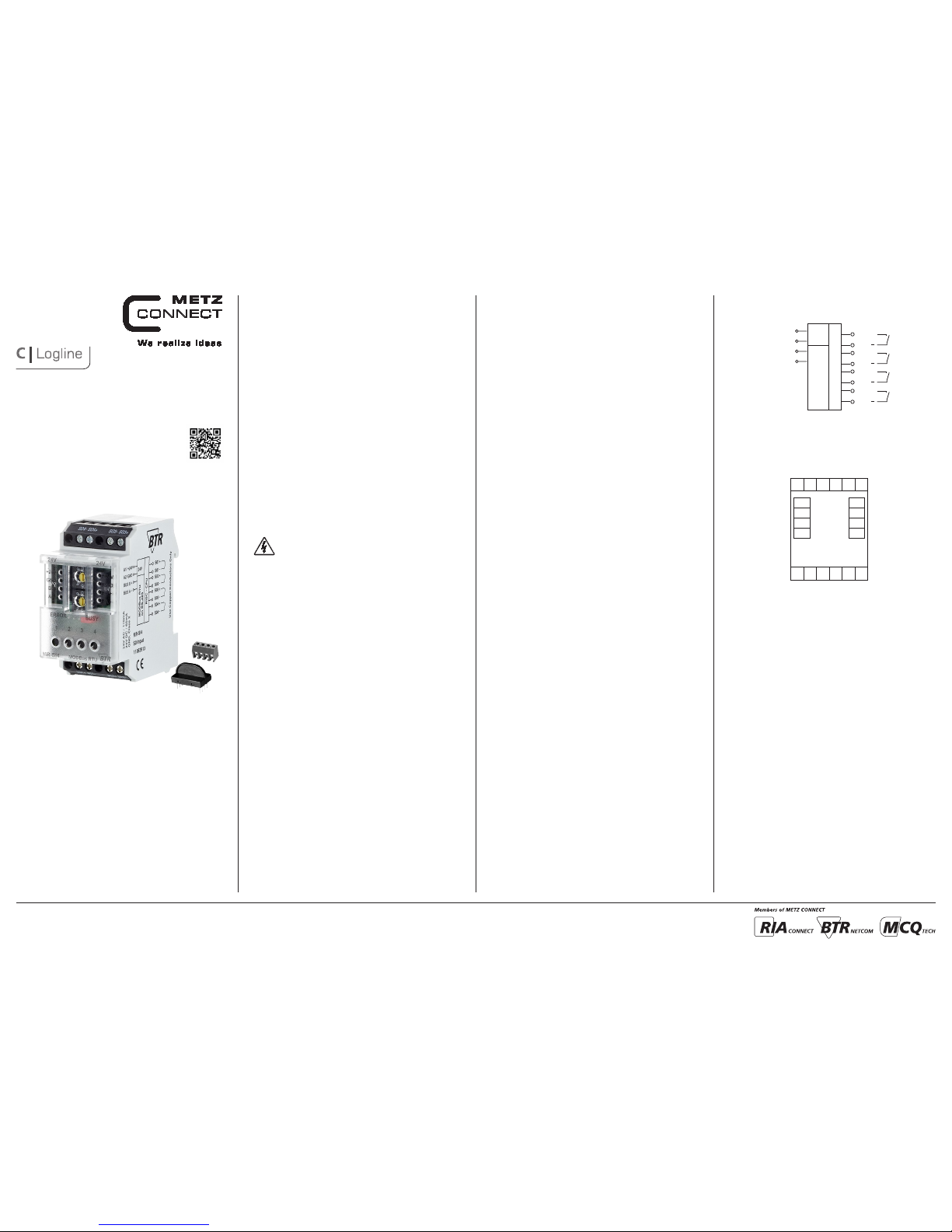
5. Connection Diagram
24 V AC/DC
GND
BUS B+
BUS A-
GND
B+
A-
+24V
B+
A-
S04-
+24V
GND
S04+
S03-
S03+
S01+
S01-
S02+
S02-
4. Wiring Diagram
A1/ +24V
A2/ GND
BUS B+
BUS A-
24V
RISC - CPU
24V AC / 170mA
24V DC / 65mA
S01+
S01
S04+
S04
S02+
S02
S03+
S03
Modbus RTU
on RS-485
Digital Input Module
MR-SI4
110 8 3 913
8096/899360
21
6. Mounting
Power down th e equipm ent.
Mount the mo dule on standard ra il (TH35 per IEC 60715 in
junctio n boxes and/or on dis tribution pane ls).
Installation
Electric installation and device termination shall be done by quali-
fied per sons only, by respe cting all applic able
specifications and regulations.
Plug in the terminal block for bus connection.
43
5 mm
65
The modul e can be aligned wit hout interspac e. Use the jumper plug
to connec t bus and supply volt age when the modul es are mounted
in serie s.
The maxi mum quantity of mod ules connected i n line is limited
to 15 or to a maximu m power consumptio n of 2 Amps (AC or
DC) per co nnection to the po wer supply. For any sim ilar block of
additional modules a separate connection to the power supply
is mandatory.
Connec t the cable f or bus supp ly.
Mounting in series.
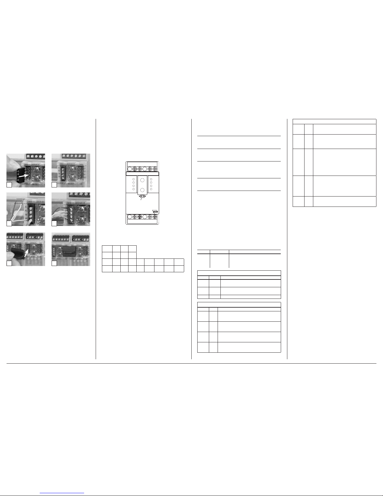
7. Bit rate and Parity setting
The bit rate a nd parity can be s et in the programmin g mode when
ajumper is p lugged behind th e front cover of the mod ule. This
jumper is re moved in normal mo de. A connection to t he bus is not
required during bit rate setting.
The bit rate o f the modules can be s et in the followin g way:
1. re move the fro nt cover of the module;
2. plug a jumpe r to the two middle pin s of the 4 pole header
betwe en the red and green L ED (Á);
3. set the de sired parity an d bit rate with the addre ss switches (Â )
in accordan ce to the chart below.
If the settings differ from the settings specified in the chart the factory
setting applies.
Factory setting: 19200 Bd Even
Switch
x1
1 2 3 4 5 6 7 8
Bitrate
(Bit/s)
1200 2400 4800 9600 19200 38400 57600 115200
Switch
x10
1 2 3
Parity even odd none
4. switch o n the supply voltage o f the module; it is now per manent-
ly saving t he bit rate in an EEPROM;
5. switch o ff the supp ly voltage of the mod ule;
6. remove th e jumper from the hea der and place the front c over.
S02+
S02-
S03+ S03-
S04+
S01+
24V 24V
ERROR
1
A
O
B +
A
-
MR-SI4
B+
A
-
+24V
GND
+24V
GND
BUSY
MODBus RTU
x1
x10
Jumper below
the faceplate
S04-
S01-
METZ CONNECT GmbH | Im Tal 2 | 78176 Blumberg | Germany | Phone +49 7702 533-0 | Fax +49 7702 533-433
Mounting instruction see www.metz-connect.com
8. Software Description
8.1 I/O Commands
“02 (0x02) Re ad Discrete Input s”
Reques t
Valid Input Starting Address 0 .. 3
Valid Quantity of Inputs 1 .. 4
Response
Byte Count 1
Input Status Bit0 .. Bit3 ( Bit4 .. Bit7 = 0 )
Information
1 = Status Input closed
0 = Status Input open
“04 (0x0 4) Read Input Regis ters”
Request
Valid Register Starting Address 20
Valid Quantity of Registers 1
Response
Byte Count 2
(Tabulator kontrollieren )
8.2 Modbus functions
The follo wing functions ar e used to read or wri te the register s. The
valid addr ess ranges are ind icated in bracket s.
Read Input Registers (0-20)
Read Holding Registers (0-43)
Write Single Register (20-43)
Write Single Register (65)
Write Multiple Registers (0-43)
For long dat a types with a le ngth of several re gisters, the se registers
are liste d directly one af ter the other and th e one with the highes t
value are in dicated first . This data can only b e transmitted in co mplete form.
Discret e Inputs (Read- Only)
Address
Name Description
0 – 3 INPUT
Switching s tatus of the input s
(switches are connected),
0: Off (sw itch is open), 1: On
(switch is c losed)
Input Register (Read-Only)
Address Name Description
0 – 11 IZ
Pulse counter
Data typ e uint48_t (3 regi sters each)
12 – 19 BZ
Calculated counter reading
Data typ e uint48_t (2 regi sters each)
20 INPUT Bits 0-3 c ontain Discret e Input 0-3
Holding Register
Address Name Description
0 – 11 IT
Copy of the pu lse counter afte r having presse d
the key
Data typ e uint48_t (3 regis ters each) (EEPRO M)
12 – 19 AZ
Initial count
Data typ e uint32_t (2 regist ers each)
Factor y setting 0 (EEPROM )
20 – 23 IE
Pulses p er unit
Data typ e uint16_t (1 register eac h)
Factor y setting 1 (EEPROM )
24 – 27 WI
Current conversion factor
Data typ e uint16_t (1 register eac h)
Factor y setting 1 (EEPROM )
(continued) Descripti on of the sof tware
28 – 31 WU
Voltage conversion factor
Data typ e uint16_t (1 register eac h)
Factor y setting 1 (EEPROM )
32 – 35 WP
Operating mode for calculation with conversion factor
Data ty pe uint16_t (1 register eac h, only bit 0 valid)
Range of val ues 0…1, see below
Factor y setting 0 (EEPROM )
36 – 39 ZS
Format of th e counter digit displ ay
Data typ e uint16_t (1 register eac h) (EEPROM)
High byte f or counter digits ,
Range o f values 0…9, factory s etting 7,
highe r values are limite d to 9
Low byte f or places after t he decimal point,
Range o f values 0…3, factor y setting 1,
highe r values are limite d to 3
40 – 43 TA
Flag for key a ctivation
Data typ e uint16_t
(1 register e ach, flag in bit 0 only )
0: key is locke d,
1: key is operati onal
factor y setting 1 (EEPRO M)
65 BAUD
Codes for b aud rates and parit y
Factor y setting 19200 baud, Eve n Parity (EEPROM)
8.3 Oper ating mod e for calcu lation wit h convers ion
factor
In the WP re gister, there is a code 0…1 that de termines, toge ther
with the co nversion facto rs WI and WU, the way how t hey are
include d in the calculation . WP, WI and WU dep end on whether
the conver ters are switc hed by the counter s, whether the cou nter
indicate s the consumption in a p rimary or secon dary way and whe ther the em itted pulses co rrespond prima rily or secondar ily to the
consumption.
A differ ence must be made be tween the follo wing electri city meter
types:
Type 1: Direc tly measuring cou nter, display: prima ry,
pulse: primary
Note: Indicates the actual consumption
Species: DIN rail counter with mechanical drum-type counting
mechanism, Ferraris counter
Type of formula: WP = 0
Factors: WI = WU = 1
IZ – IT
BZ = (------- --- + A Z) ∙ WI ∙ WU , BZ = counter re ading = cons umption
IE
Type 2: Conver sion counter, display : primary, pulse: s econdary
Note: Indicates the actual consumption
Species: Counter with LCD display
Type of formula: WP = 1
Factors: WI and WU correspond to the converters
IZ – IT
BZ = (------- --- ∙ W I ∙ WU) + AZ , BZ = counter re ading = consu mption
IE
Type 3: Conver sion counter, display : primary, pulse: p rimary
Note: Indicates the actual consumption
Species: Counter with LCD display, multi-function meters
Type of formula: WP = 0
Factors: WI = WU = 1
IZ – IT
BZ = (------- --- + A Z) ∙ WI ∙ WU , BZ = counter re ading = cons umption
IE

METZ CONNECT GmbH | Im Tal 2 | 78176 Blumberg | Germany | Phone +49 7702 533-0 | Fax +49 7702 533-433
Mounting instruction see www.metz-connect.com
(continued) Descripti on of the sof tware
Type 4: Conver sion counter, displa y: secondary, pul se: secondary
Note: Indicates the consumption reduced by the converter factors
Species: DIN rail counter with mechanical
drum-type counting mechanism, Ferraris counter
Type of formula: WP = 0
Consumpt ion and display of the co nverter counter a re different.
Both can be c alculated using a di fferent confi guration (WI, WU ).
Factors : WI = WU = 1:
The calcu lated counter rea ding correspond s to the display
of the conve rter counter.
Factors : WI and WU corre spond to the conver ters:
The calcu lated counter rea ding correspond s to the
consumption.
IZ – IT
BZ = (------- --- + A Z) ∙ WI ∙ WU , BZ = counter readi ng or consumptio n
IE
8.4. Commissioning
The user r eads on site the initi al count from the ele ctricity me ter and
presse s the key on the MR-SI4. A fter this key pre ss, the pulse counte r
of regist er IZ is copied into re gister IT.
After wards, the user con figures the MR-SI4 v ia the Modbus using a
servi ce program. The fol lowing must be ente red:
• initial count read from the counter
• pulses p er unit,
e.g. indicat ion on the electr icity meter 2000 p ulses per kWh
• formula t ype for calculatio n with converter fa ctors
• factor for current conversion,
e.g. indicat ion on the converte r 200/5A → factor = 40
• factor for voltage conversion,
e.g. indicat ion on the converte r 20000/100V → facto r = 200
• number of dig its and places aft er the decimal point
• deacti vate the key to protec t the IT register
8.5.Details for calculation
The calcu lated counter rea ding should behave e xactly in the s ame
way as the ele ctricity me ter. This requires t hat there should be n o
overf lows and rounding of f errors for the in termediate resu lts.
Theref ore, particular ly large data typ es are used for coun ting and
calculation.
Every 6 0 milliseconds, a pu lse can be emitte d by the electr icity meter.
This resu lts in up to 1,440,000 p ulses per day or abou t 526,000,000
pulses p er year.
If the puls e counter was realize d with 4 bytes, it c ould be count to
4,294,967,295. At hig hest pulse freq uency, this would be e nough for
approx. 8. 2 years.
Theref ore it is realized wi th 6 bytes and cann ot overflow.
The numbe r of places after th e decimal point is con sidered as an ad-
ditional m ultiplier with a po wer of ten during the c alculation.
Furthe rmore, it determi nes the place of the de cimal point in the
display of BZ a nd AZ.
As for the e lectricit y counter which only h as a specified nu mber of
decimal p laces, the number of p laces is limited w ith the last step in
the calcu lation. This is why th e calculated count er reading of the MRSI4 over flows to 0 as often as t he counter reading o f the electric ity
met er.
Calcula ted counter readi ng, if WP is 0.
BZ = ( (uint96_t ) (IZ - IT)*WU*W I*Power of ten [plac es after decima l
point] / IE +
(uint96_t) A Z * WU * WI )
% power of ten [di gits]
Calcula ted counter readi ng, if WP is 1.
BZ = ( (uint96_t ) (IZ - IT)*WU*W I*Power of ten [plac es after decima l
point] / IE +
(uint96_t) A Z )
% power of ten [di gits]
(continued) Descripti on of the sof tware
8.6 Bit rate se tting wi th Modbus c ommand
Parity and bit rate have the same value as when setting them by
address switch.
If Parity or Bit has the value 0, no setting or storage is carried out.
The register content is stored in the EEPROM.
“06 (0x06) Write Single Register”
Request
Valid Register Address 0x41 ( 65 )
Valid Register Value 2 Bytes
Bit 15-8: Magic-Number 0x53 = 83 as protection against
accidental writing.
The command will be further analysed only with this number.
Response
Echo of Request
Example for a frame:
Slave address 0x12 Setting of rotary switch (18)
Function 0x06 Write Single Register
Register address Hi 0x00
Register address Lo 0x41 Bit rate and parity (65)
Register contents Hi 0x53 Magic-Number
Register contents Lo 0x15 Parity Even, 19200 Baud
All devi ces can be switch ed simultaneou sly with a Broadc ast command (Slave a ddress 0x00) Ho wever, it is advise d not to do so as this
can cause p roblems:
- Devices from other manufacturers may have under this
address a register for a different purpose that will then
be operated in the wrong way.
- There is no feedback from the individual devices.
Consequently the control cannot immediately recognize
if the command was correctly received.
It is safer to a ddress and swit ch each device indi vidually.
The devi ce will then answe r with the old sett ings of parity and b it
rate. Switch ing will take place o nly afterwar ds. However, the answ er
can get los t if the bus is disturb ed.
When all de vices are switc hed; it is advised t o check communicat ion.
Any func tion of the device pr oviding a feedba ck is suitable. If a sin gle
functi on is to be used being in dependent from t he process per iphery
then the fu nction „Diagno stic“ sub-func tion „Return Que ry Data“ is
suitabl e, it returns the tran sferred data.
If bit rate an d parity sett ing of a device are unkn own it is possible t o
address t he device succes sively with all c ombinations of bit rat e and
parity u ntil the device ans wers. Try the most l ikely combinatio ns first.
Try the lowe r bit rates last as the y take longer.
(continued) Descripti on of the sof tware
8.7 General Commands
“08 (0x08) Diagnostics”
Subfunct ion “0 ( 0x0000) Re turn Query Data”
Data Field Any
Response: Echo of Request
Subfunction “1 (0x0001) Restart Communication Option”
Data Field 0x0000 oder 0xFF00
Response: Echo of Request
Action: Clears all Error Counters, Restarts node
Subfunct ion “4 (0x0004) Force L isten Only Mode”
Data Field 0x0000
No Response
Action: No response until Node Reset or Function Code 08
Subcode 01
Subfunct ion “10 ( 0x000A) Clea r Counters”
Data Field 0x0000
Response: Echo of Request
Action: Clears all Error Counters
Subfunct ion “11 ( 0x000B ) Return Bus Messa ge Count”
Data Field 0x0000
Response: Quantity of messages that the remote device has
detected on the communications system since its last restart,
clear counters operation, or power-up.
Subfunct ion “12 ( 0x000C) Ret urn Bus Communicati on Error Count”
Data Field 0x0000
Response: Quantity of errors encountered by the remote
device since its last restart, clear counters operation,
or power-up. (CRC, Length <3, Parity, Framing)
Subfunct ion “13 ( 0x000 D) Return Bus Excep tion Error Count”
Data Field 0x0000
Response: Quantity of MODBUS exception responses returned
by the remote device since its last restart, clear counters
operation, or power-up.
Subfunct ion “14 (0x000E) Retu rn Slave Message Co unt”
Data Field 0x0000
Response: quantity of messages addressed to the remote
device, or broadcast, that the remote device has processed
since its last restart, clear counters operation, or power-up.
Subfunct ion “15 (0x00 0F) Return Slave No R esponse Count”
Data Field 0x0000
Response: Quantity of messages addressed to the remote
device for which it has returned no response (neither a normal
response nor an exception response), since its last restart, clear
counters operation, or power-up.
15 14 13 12 11 10 9 8 7 6 5 4 3 2 1 0
0x53 Parität Bitrate
Bit 3-0 1 2 3 4 5 6 7 8
Bitrate 1200 2400 4800 9600 19200 38400 57600 115200
Bit 7-4 1 2 3
Parität even odd none
(continued) Descripti on of the sof tware
“43 /14 (0x2B / 0x0E) Read Device Identification”
Request
Read Device ID code: 0x01
Object ID 0x00
Response
Device ID code 0x01
Conformity level 0x01
More follows 0x00
Next object ID 0x00
Number of objects 0x03
Object ID 0x00
Object Length 0x03
Object Value “BTR”
Object ID 0x01
Object Length 0x06
Object Value “MR-SI4”
Object ID 0x02
Object Length 0x04
Object Value “V2.0”
 Loading...