

Metz Connect MR-SI4, MR-DI10 User Manual
METZ CONNECT GmbH | Im Tal 2 | 78176 Blumberg | Germany | Phone +49 7702 533-0 | Fax +49 7702 533-433
Mounting instruction see www.metz-connect.com
1. Description
The Modbu s module with 4 S0 inpu ts to DIN EN 62053-31 class A
was devel oped for decentr alized switchin g tasks. It is suit able for
counting S0 c ounter pulses. T his allows very g ood integration of t he
module into a n energy controll ing system. In ca se of a power failure,
the last co unter readings are s aved. The inputs c an be scanned
by means of st andard object s via a Modbus maste r. The module
address , the baud rate and the p arity are set by me ans of two
address s witches on the fr ont.
Suitable f or decentralize d mounting in seria l sub-distribu tor.
2. Declaration of Conformity
The devi ce was tested accor ding to the applicab le standards. Co nformit y was proofed. The de claration of confo rmity is availabl e at
the manufacturer METZ CONNECT GmbH.
Notes Regarding Device Description
These in structions inc lude indications f or use and mounting of th e
device. In c ase of questions t hat cannot be answe red with these
instructions please consult supplier or manufacturer.
The indic ated installati on directions or r ules are applica ble to the
Federa l Republic of Germa ny. If the device is use d in other countrie s
it applie s to the equipment ins taller or the use r to meet the
national directions.
Safety Instructions
Keep the ap plicable direc tions for industr ial safety and pr evention of
accident s as well as the VDE rul es.
Technician s and/or installe rs are informed th at they have to
elect rically dischar ge themselves a s prescribed be fore installati on or
maintenan ce of the devices.
Only quali fied personn el shall do mounting an d installation wo rk
with the de vices, see se ction “qualifie d personnel”.
The inform ation of these ins tructions have to b e read and understood by e very person us ing this device.
Symbols
Warning of dangerous electrical voltage
Danger
means that non-observance may cause risk of life,
grievous bodily harm or heavy material damage.
Qualified Personnel
Qualifi ed personnel in t he sense of these i nstructions ar e persons
who are wel l versed in the use a nd installation of s uch devices and
whose pro fessional quali fication meet s the requireme nts of their
work.
This includes for example:
• Qualifi cation to co nnect the device a ccording to the VDE
specif ications and the loc al regulations and a qu alification to put
this devi ce into operation, to po wer it down or to activ ate it by
respecting the internal directions.
• Knowle dge of safety rule s.
• Knowle dge about applicat ion and use of the devic e within the
equipme nt system etc.
3. Technical Data
Modbus Interface
Protocol l Modbus RT U
Transmissio n rate 1200 ... 115200 Bd
(factor y setting 19200 Bd Even)
Cabling RS485 t wo wire bus with volt age
equalizin g cable in bus / line topo logy
terminate with 120 Ohms
Supply
Operati ng voltag e range 20 ... 28 V AC/D C (SELV)
Current co nsumption 170 mA (AC) / 65 mA (DC )
Relativ e duty cycle 100 %
Input
4x S0 input acc ording to DIN EN 62053-31 Cla ss A
Housing
Dimensio ns WxHxD 1.4 x 2.8 x 3.0 in. (35 x 70 x 65 mm)
Weight 95 g
Mounting position any
Mounting standar d rail TH35 per IEC 60715
Mounting in s eries the max imum quantity of modu les
witho ut space connec ted in line is limited to 15 or
to a maxim um power consumptio n of
2 Amps (A C or DC) per connec tion to
the powe r supply. For any similar
block of a dditional module s a
separate connection to the power
supply is ma ndatory.
Material
Housing Po lyamide 6. 6 V0
Terminal blocks Polyamide 6.6 V0
Cover plate Polycarbonate
Type of prote ction
(IEC 60529)
Housing IP40
Terminal blocks IP20
Terminal blocks
Supply and b us
4 pole terminal bloc k max. AWG 16 (1.5 mm²) solid w ire
max. AWG 18 (1.0 mm²) stran ded wire
Wire diame ter min. 0.3 mm up to ma x. 1.4 mm
(terminal b lock and jumper plug ar e
include d to each pack ing unit)
Module connection
Input/Ou tput max. AWG 12 (4.0 mm²) so lid wire
max. AWG 14 (2.5 mm ²) stranded wire
Wire diame ter min. 0.3 mm up to ma x 2.7 mm
Temperature range
Operati on -5 °C ... +55 °C
Storage -20 °C ... +70 °C
Protec tive circuitry polarit y reversal prote ction of
operating voltage
polarit y reversal prot ection o f supply
and bus
Display
Operati ng and bus activit y green LED
Error indic ation red LED
Status of the i nputs yellow L ED
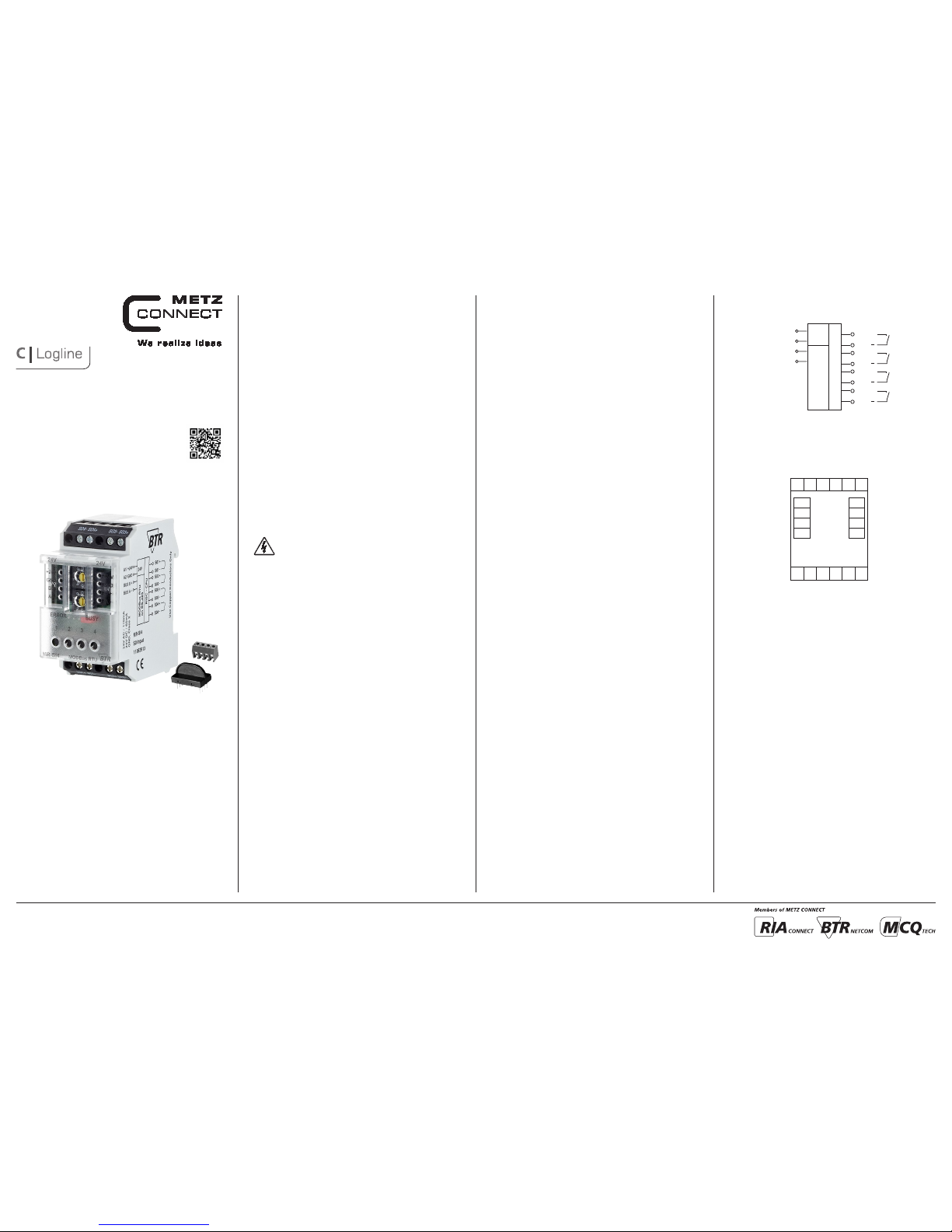
5. Connection Diagram
24 V AC/DC
GND
BUS B+
BUS A-
GND
B+
A-
+24V
B+
A-
S04-
+24V
GND
S04+
S03-
S03+
S01+
S01-
S02+
S02-
4. Wiring Diagram
A1/ +24V
A2/ GND
BUS B+
BUS A-
24V
RISC - CPU
24V AC / 170mA
24V DC / 65mA
S01+
S01
S04+
S04
S02+
S02
S03+
S03
Modbus RTU
on RS-485
Digital Input Module
MR-SI4
110 8 3 913
8096/899360
21
6. Mounting
Power down th e equipm ent.
Mount the mo dule on standard ra il (TH35 per IEC 60715 in
junctio n boxes and/or on dis tribution pane ls).
Installation
Electric installation and device termination shall be done by quali-
fied per sons only, by respe cting all applic able
specifications and regulations.
Plug in the terminal block for bus connection.
43
5 mm
65
The modul e can be aligned wit hout interspac e. Use the jumper plug
to connec t bus and supply volt age when the modul es are mounted
in serie s.
The maxi mum quantity of mod ules connected i n line is limited
to 15 or to a maximu m power consumptio n of 2 Amps (AC or
DC) per co nnection to the po wer supply. For any sim ilar block of
additional modules a separate connection to the power supply
is mandatory.
Connec t the cable f or bus supp ly.
Mounting in series.
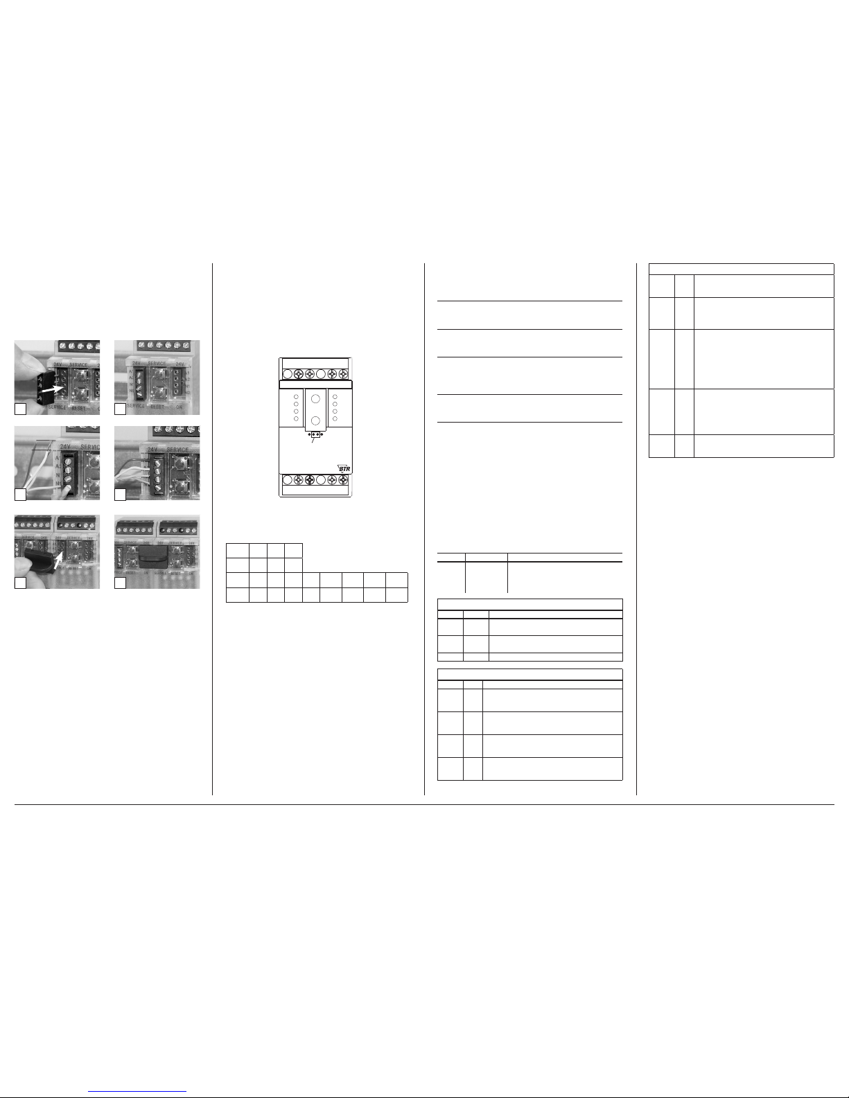
7. Bit rate and Parity setting
The bit rate a nd parity can be s et in the programmin g mode when
ajumper is p lugged behind th e front cover of the mod ule. This
jumper is re moved in normal mo de. A connection to t he bus is not
required during bit rate setting.
The bit rate o f the modules can be s et in the followin g way:
1. re move the fro nt cover of the module;
2. plug a jumpe r to the two middle pin s of the 4 pole header
betwe en the red and green L ED (Á);
3. set the de sired parity an d bit rate with the addre ss switches (Â )
in accordan ce to the chart below.
If the settings differ from the settings specified in the chart the factory
setting applies.
Factory setting: 19200 Bd Even
Switch
x1
1 2 3 4 5 6 7 8
Bitrate
(Bit/s)
1200 2400 4800 9600 19200 38400 57600 115200
Switch
x10
1 2 3
Parity even odd none
4. switch o n the supply voltage o f the module; it is now per manent-
ly saving t he bit rate in an EEPROM;
5. switch o ff the supp ly voltage of the mod ule;
6. remove th e jumper from the hea der and place the front c over.
S02+
S02-
S03+ S03-
S04+
S01+
24V 24V
ERROR
1
A
O
B +
A
-
MR-SI4
B+
A
-
+24V
GND
+24V
GND
BUSY
MODBus RTU
x1
x10
Jumper below
the faceplate
S04-
S01-
METZ CONNECT GmbH | Im Tal 2 | 78176 Blumberg | Germany | Phone +49 7702 533-0 | Fax +49 7702 533-433
Mounting instruction see www.metz-connect.com
8. Software Description
8.1 I/O Commands
“02 (0x02) Re ad Discrete Input s”
Reques t
Valid Input Starting Address 0 .. 3
Valid Quantity of Inputs 1 .. 4
Response
Byte Count 1
Input Status Bit0 .. Bit3 ( Bit4 .. Bit7 = 0 )
Information
1 = Status Input closed
0 = Status Input open
“04 (0x0 4) Read Input Regis ters”
Request
Valid Register Starting Address 20
Valid Quantity of Registers 1
Response
Byte Count 2
(Tabulator kontrollieren )
8.2 Modbus functions
The follo wing functions ar e used to read or wri te the register s. The
valid addr ess ranges are ind icated in bracket s.
Read Input Registers (0-20)
Read Holding Registers (0-43)
Write Single Register (20-43)
Write Single Register (65)
Write Multiple Registers (0-43)
For long dat a types with a le ngth of several re gisters, the se registers
are liste d directly one af ter the other and th e one with the highes t
value are in dicated first . This data can only b e transmitted in co mplete form.
Discret e Inputs (Read- Only)
Address
Name Description
0 – 3 INPUT
Switching s tatus of the input s
(switches are connected),
0: Off (sw itch is open), 1: On
(switch is c losed)
Input Register (Read-Only)
Address Name Description
0 – 11 IZ
Pulse counter
Data typ e uint48_t (3 regi sters each)
12 – 19 BZ
Calculated counter reading
Data typ e uint48_t (2 regi sters each)
20 INPUT Bits 0-3 c ontain Discret e Input 0-3
Holding Register
Address Name Description
0 – 11 IT
Copy of the pu lse counter afte r having presse d
the key
Data typ e uint48_t (3 regis ters each) (EEPRO M)
12 – 19 AZ
Initial count
Data typ e uint32_t (2 regist ers each)
Factor y setting 0 (EEPROM )
20 – 23 IE
Pulses p er unit
Data typ e uint16_t (1 register eac h)
Factor y setting 1 (EEPROM )
24 – 27 WI
Current conversion factor
Data typ e uint16_t (1 register eac h)
Factor y setting 1 (EEPROM )
(continued) Descripti on of the sof tware
28 – 31 WU
Voltage conversion factor
Data typ e uint16_t (1 register eac h)
Factor y setting 1 (EEPROM )
32 – 35 WP
Operating mode for calculation with conversion factor
Data ty pe uint16_t (1 register eac h, only bit 0 valid)
Range of val ues 0…1, see below
Factor y setting 0 (EEPROM )
36 – 39 ZS
Format of th e counter digit displ ay
Data typ e uint16_t (1 register eac h) (EEPROM)
High byte f or counter digits ,
Range o f values 0…9, factory s etting 7,
highe r values are limite d to 9
Low byte f or places after t he decimal point,
Range o f values 0…3, factor y setting 1,
highe r values are limite d to 3
40 – 43 TA
Flag for key a ctivation
Data typ e uint16_t
(1 register e ach, flag in bit 0 only )
0: key is locke d,
1: key is operati onal
factor y setting 1 (EEPRO M)
65 BAUD
Codes for b aud rates and parit y
Factor y setting 19200 baud, Eve n Parity (EEPROM)
8.3 Oper ating mod e for calcu lation wit h convers ion
factor
In the WP re gister, there is a code 0…1 that de termines, toge ther
with the co nversion facto rs WI and WU, the way how t hey are
include d in the calculation . WP, WI and WU dep end on whether
the conver ters are switc hed by the counter s, whether the cou nter
indicate s the consumption in a p rimary or secon dary way and whe ther the em itted pulses co rrespond prima rily or secondar ily to the
consumption.
A differ ence must be made be tween the follo wing electri city meter
types:
Type 1: Direc tly measuring cou nter, display: prima ry,
pulse: primary
Note: Indicates the actual consumption
Species: DIN rail counter with mechanical drum-type counting
mechanism, Ferraris counter
Type of formula: WP = 0
Factors: WI = WU = 1
IZ – IT
BZ = (------- --- + A Z) ∙ WI ∙ WU , BZ = counter re ading = cons umption
IE
Type 2: Conver sion counter, display : primary, pulse: s econdary
Note: Indicates the actual consumption
Species: Counter with LCD display
Type of formula: WP = 1
Factors: WI and WU correspond to the converters
IZ – IT
BZ = (------- --- ∙ W I ∙ WU) + AZ , BZ = counter re ading = consu mption
IE
Type 3: Conver sion counter, display : primary, pulse: p rimary
Note: Indicates the actual consumption
Species: Counter with LCD display, multi-function meters
Type of formula: WP = 0
Factors: WI = WU = 1
IZ – IT
BZ = (------- --- + A Z) ∙ WI ∙ WU , BZ = counter re ading = cons umption
IE
 Loading...