

Page 1
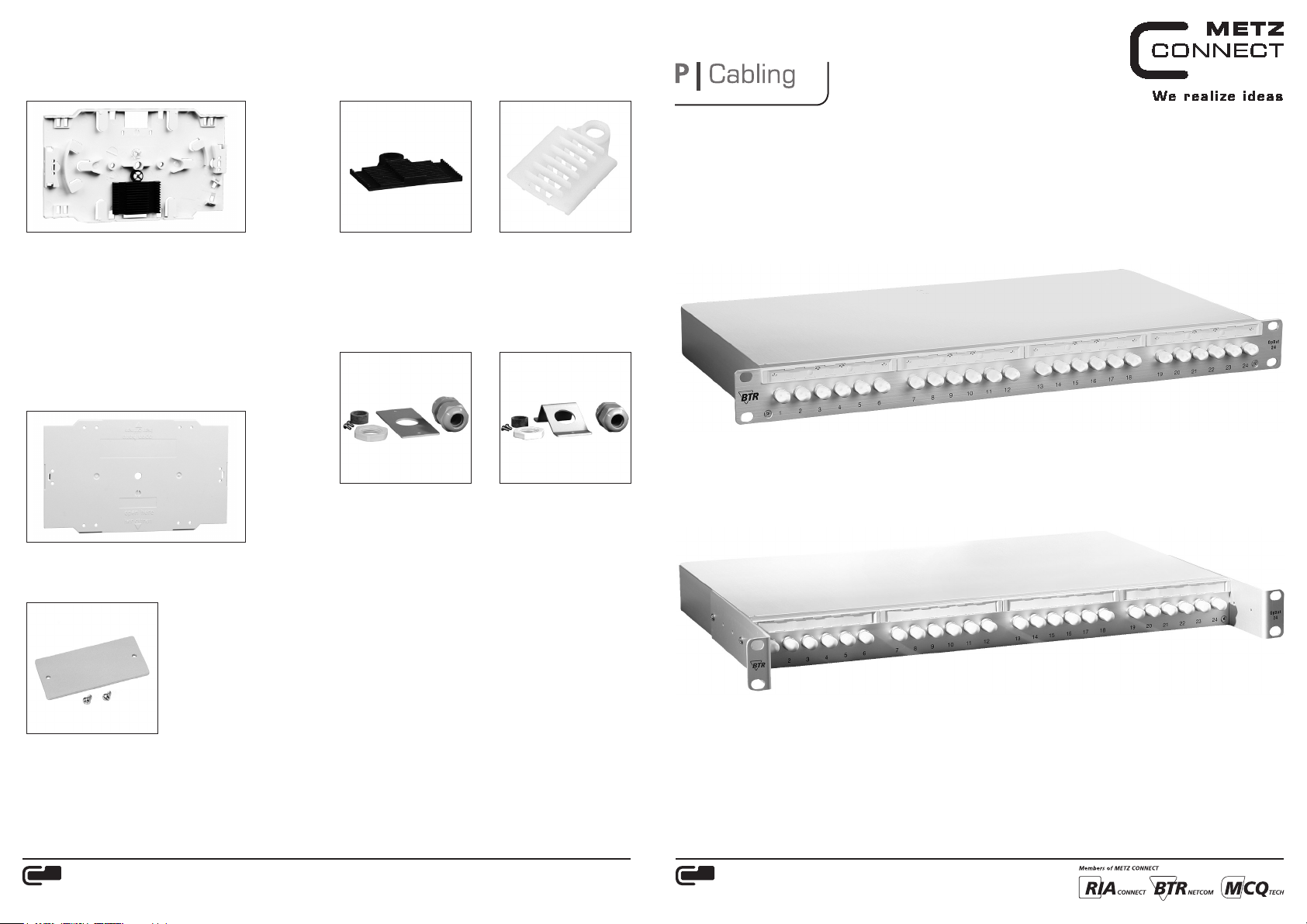
Zubehör
Accessories
Spleißkassette / Splice Tray
Spleißkassette standard, unbestückt 1509010000-E
Splice Tray standard, unequipped
Spleißkassette standard,
komplett für 12 Crimpspleiße 1509010001-E
Splice Tray standard, equipped
for 12 crimp splices
Spleißkassette standard,
komplett für 12 Schrumpfspleiße 1509010002-E
Splice Tray standard, equipped
for 12 shrink splices
Deckel für Spleißkassette
Cover Plate for Splice Tray
Deckel für Spleißkassette 15090200-E
Cover Plate for splice tray
Verschlussplatte / Cover Plate
Spleißhalter / Splice Holder
Spleißhalter
für 12 Crimpspleiße
Splice Holder
for 12 crimp splices
15090301-I
Spleißhalter
für 6 Schrumpfspleiße
Splice Holder
for 6 shrink splices
15090302-I
Kabeleinführung gerade und schräg
Cable infeed straight and inclined
Kabeleinführung G PG16
gerade inkl. PG16
Verschraubung
Cable infeed G PG16
straight with PG16 cable gland
15081102-E
Kabeleinführung G PG21
gerade inkl. PG21
Verschraubung
Cable infeed G PG21
straight with PG21 cable gland
15081103-E
Kabeleinführung S PG16
schräg inkl. PG16
Verschraubung
Cable infeed G PG16
inclined with PG16 cable gland
15081104-E
Kabeleinführung S PG21
schräg inkl. PG21
Verschraubung
Cable infeed G PG21
inclined with PG21 cable gland
15081105-E
OpDAT System Patchfeld Festeinbau
OpDAT System patch panel fixed installation
Montagehinweis | Mounting instructions
OpDAT PF
Art.-Nr. | P/N 15020xxxxxx
8928/899818
OpDAT PR (rücksetzbar/resettable)
Art.-Nr. | P/N 15021xxxxxx
Verschlussplatte für Kabeleinführung
Cover Plate for cable infeed
15081101-E
METZ CONNECT GmbH | Im Tal 2 | 78176 Blumberg | Ge rmany
Phone +49 7702 533-0 | Fax +49 7702 533-433
Weiter e Dokumentation siehe / a dditional documentat ion see /
docume ntation supplé mentaire voir www.metz-connect.com
METZ CONNECT GmbH | Im Tal 2 | 78176 Blumberg | Ge rmany
Phone +49 7702 533-0 | Fax +49 7702 533-433
Weiter e Dokumentation siehe / a dditional documentat ion see /
docume ntation supplé mentaire voir www.metz-connect.com
Page 2
Kabelmontage | Cable mounting
Kabelmontage | Cable mounting
Inhalt der Verpackung | Contents
Im Auslieferungszustand sind die Kupplungen montiert und die
rückseitigen Öffnungen durch Schaumstoffteile ver schlossen. 4
Kabelbinder zur Zugentlastung sowie 3 selbstklebende Clipse zur
Kabelführung liegen bei.
Spleißkassette, -halter, und -schutze sind Sonderzubehör und
extra zu bestellen (Ausnahme: komplett bestückte Patchfelder).
Verschlussplatten und Kabeleinführungen mit PG-Verschraubung
gehören ebenfalls nicht zur Grund ausstattung!
When delivered, couplers are mounte d and the openings on
the back are close d with foam material. 4 cable ties for strain
relief and 3 self-adhesive clips for cable guiding are included to
delivery.
Splice tray, splice holder and splice protec tions are accessories
and have to be ordered separately. (Exception: completely
equipped patch panels). Cover plates and cable infeeds with
cable glands, too, are not part of the basic equipment!
Schritt 1 | Step 1
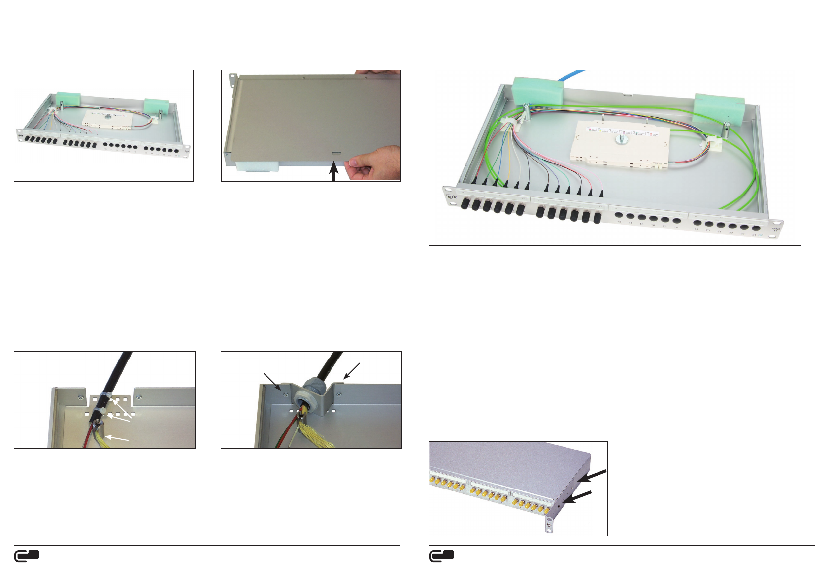
Zum Öffnen der Panels (Festeinbau / rücksetzbar) Gehäuse festhalten und Deckel an der Rückseite nach oben abheben.
To open the panel (fixed mounting / resettable) hold the
housing and lift the cover upwards to take off.
Schritt 2a | Step 2a Schritt 2b | Step 2b
À
Schritt 3 | Step 3
1. Rändelmutter lösen.
2. Spleißkassetten vom Stapel nehmen und Adern aus Kabelführungselementen wickeln.
3. Spleißkassetten zum Spleißgerät führen und Bündeladern an Spleißkassette mit Kabelverbinder fixieren.
4. Fasern des Kabels und Pigtails verspleißen. Spleißschutze in Kassette ablegen. Dabei auf größtmöglichen
Biegeradius (mindestens 30 mm) und spannungsfreie Ablage der Faser achten.
5. Adern wieder aufwickeln und in Patchfeld einlegen. Auf Torsion achten.
6. Oberste Spleißkassette mit Deckel verschließen und mit Rändelschrauben sichern.
Beim Einsatz mehrerer Kassetten darauf achten, dass beim Stapeln keine Faser versehentlich eingeklemmt wird.
7. Deckel einrasten.
1. Unscrew the knurled nut.
2. Take the splice trays from the pile and unwrap the tubes from the cable guide elements.
3. Bring the splice tray to the splice unit and fix the loose tubes with cable ties to the splice tray.
4. Splice the fibers of the cable with the pigtails. Place the splice protections into the tray. Take care to respect the largest possible
bending radius (min. 30 mm) and a stress-free storage of the fibers.
5. Rewrap the tubes and place them into the patch panel. Auf Torsion achten.
6. Close the upper splice tray with the cover and secure with knurled screws. When using several trays take care not to pinch fibers
accidentally when piling the trays.
7. Click the cover into place.
Zurücksetzen des Patchfeldes (nur bei rücksetzbarer Version möglich)
Reset the patch panel (only with resettable versions)
Á
LWL-Installationskabel ca. 3 m abmanteln (1,5 m Bündelader und
1,5 m abisolierte Faser). Das Kabel mit beiliegenden Kabelbindern
befestigen À. Kevlar im geschlitzten Bolzen festlegen Á. ...
Strip the fiber optic cable by about 3 m (1.5 m loose tube and 1.5
m stripped fiber). Fasten the cable with the cable ties enclosed. À.
Fix the Kevlar in the slotted bolt Á. ....
METZ CONNECT GmbH | Im Tal 2 | 78176 Blumberg | Ge rmany
Phone +49 7702 533-0 | Fax +49 7702 533-433
Weiter e Dokumentation siehe / a dditional documentat ion see /
docume ntation supplé mentaire voir www.metz-connect.com
Soll das Kabel über eine PG-Verschraubung (Art.-Nr. siehe Zubehör)
zugentlastet werden, so ist die PG-Verschraubung zunächst über
das Kabel zu schieben und zu fixieren. Danach erst komplette
Kabelzuführungseinheit mit der Rückwand verschrauben.
To strain relief the cable by a cable gland (P/N see accessories) push
the cable gland first over the cable and secure it. Then screw the
complete cable feed unit to the back.
METZ CONNECT GmbH | Im Tal 2 | 78176 Blumberg | Ge rmany
Phone +49 7702 533-0 | Fax +49 7702 533-433
Weiter e Dokumentation siehe / a dditional documentat ion see /
docume ntation supplé mentaire voir www.metz-connect.com
Bei der Version mit rück setzbarer Frontplatte können die seitlichen Befestigungsflügel um 30 mm bzw. 60 mm nach vorne
verschoben werden. Hierzu die Befestigungs schrauben vollständig lösen und die Winkel entsprechend den vorliegenden
Erfordernissen versetzen.
The lateral fastening brackets c an be pushed for ward by 30 mm
or 60 mm on versions with a resett able front plate. To do so
unscrew the fastening screws completely and move the brackets
as required.
 Loading...