

Page 1
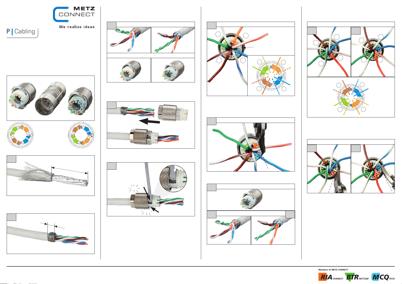
Kabelanschluss erstes Kabelende
mit Auswahl weißes Ladestück
Kabelverbinder Class F
AWG 24/1-22/1, AWG 24/7-22/7
130 8 6 3 - 02-E
Montagehinweis
Verbindergehäuse
weißes Ladestück
graues Ladestück
1
35
A
3
erstes Kabelende
weißes Ladestück graues Ladestück
7350/899316
Ladestück anhand der Farbanordnung mit übereinstimmmender
Anordnung der Adernpaare des K abels a uswähl en.
Auswahl weiße s Lade stück : nach Schritt 4+5 weiter mit S chrit t 6
Auswahl graues Ladestück: nach Schritt 4+5 weiter mit Schritt 11
4
Kabel in das Ladestück einführen, bis das Schirmgeflecht auf d er
Höhe der Schirmklamme rn lieg t.
5
6
2.
GR
BR-WS
1.
BR
Adernpaare aufdrille n. Mit Paar braun be ginnen d die Dräht e entsp rechend der Farbkodierung in die Fuge n des Ladest ückes legen.
Beim Einlegen der Drähte ist unbe dingt die Reihenfolge ei nzuhalten:
1. braun, 2. grün, 3. o range, 4. b lau
7
Adern bündig am Gehäuse rand abs chneiden.
weißes Ladestück
GR-WS
BL- WS
weißes Ladestück
OR
OR-WS
3.
Führungsnut
BL
GR-WS
4.
GR
BR-WS
2.
1.
BR
bündig
abschneiden
OR
3.
4.
BL-W S
OR-WS
BL
graues Ladestück
9a 9b
BR-WS
GR
GR-WS
Adernpaare aufdrille n. Mit Paar braun be ginnen d die Dräht e entsprechend der Farbkodierung in die Fuge n des Ladest ückes legen.
Beim Einlegen der Drähte ist unbe dingt die Reihenfolge ei nzuhalten:
1. braun, 2. grün, 3. o range, 4. b lau
BL- WS
BR
1.
2.
BR-WS
GR
BL
4. 4.
OR-WS
3.
OR
BR
1.
2.
GR-WS
BR-WS
GR
OR
1.
2.
BL- WS
4.
3.
BR
GR-WS
BL
OR-WS
BL- WS
BL
OR-WS
3.
OR
graues Ladestück
10a 10b
bündig
abschneiden
1.
click
Kunst stoffmantel c a. 35 mm abis olieren und Geflechtschirm nach
hinten legen.
2
5
Geflechtschirm gleichmäßig um den Folienschirm drehen.
Folienschirm einkerben und entfernen.
METZ CONNECT | Im Tal 2 | 78176 Blumberg | Deutschland | Tel. +49 7702 533-0 | Fax +49 7702 533-433
Vertrieb durch RIA CONNECT GmbH und BTR NETCOM GmbH
Montageanleitung siehe www.metz-connect.com
Die 2 Schi rmklammern mi t einem k leine n Schraubendreher in die
Verrastung drücken.
click
8
2.
8a 8b
Zum Ansc hließen des zweiten Kabel endes sind die Schritte 1 und 2,
sowie 4 und 5 zu wiederholen.
Hinweis: Je nach K abelaustritt am zweiten K abele nde kann auch keine
Kreuzung der Adernpaare blau un d grün auf treten
graues Ladestück
zweites Kabelende
bündig
Adern bündig am Gehäuse rand abs chneiden.
abschneiden
Page 2
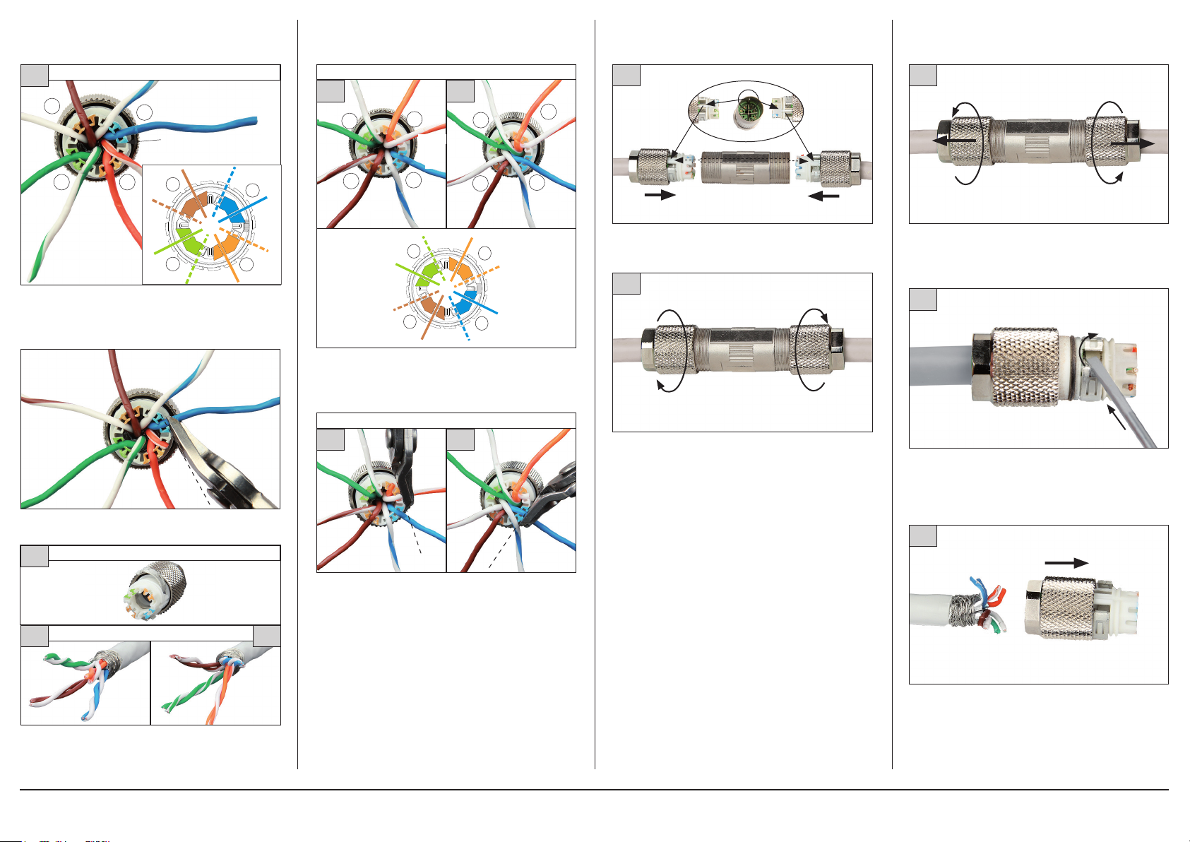
Kabelanschluss erstes Kabelende
mit Auswahl graues Ladestück
Demontage
11
1
BR-WS
GR
2.
GR-WS
Adernpaare aufdrille n. Mit Paar braun be ginnen d die Dräht e entsprechend der Farbkodierung in die Fuge n des Ladest ückes legen.
Beim Einlegen der Drähte ist unbe dingt die Reihenfolge ei nzuhalten:
1. braun, 2. grün, 3. o range, 4. b lau
12
graues Ladestück
BR
3.
OR
graues Ladestück
4.
OR-WS
BR-WS
GR
BL- WS
BL
Führungsnut
BR
1.
2.
GR-WS
abschneiden
bündig
BL-W S
3.
OR
4.
OR-WS
BL
weißes Ladestück
14a 15b
GR
BR-WS
Adernpaare aufdrille n. Mit Paar braun be ginnen d die Dräht e entsp rechend der Farbkodierung in die Fuge n des Ladest ückes legen.
Beim Einlegen der Drähte ist unbe dingt die Reihenfolge ei nzuhalten:
1. braun, 2. grün, 3. o range, 4. b lau
GR-WS
2.
1.
BR-WS
OR
3.
OR-WS
BR-WS
BL
4.
BL- WS
GR-WS
2.
GR
1.
BR
GR-WS
GR
2.
1.
BRBR
OR
3.
OR-WS
BL
4.
BL- WS
OR
3.
OR-WS
BL
4.
BL- WS
weißes Ladestück
15a 15b
16
Führungsnut
Beim Zus ammenf ühren Führungsnut beider Lad estücke und Steg des
Verbindergehäuses aufeinander ausrichten...
Führungsnut
17
1 Nm
... und Lad estücke mit Steckergehäuse fe st ver schrauben.
Zur sicheren Kontaktierung 1 Nm Drehmoment verwenden.
1 Nm
1
Lade stücke vom Verbin derge häuse ab drehen...
2
2.
1.
... die 2 Schirmklammern mit einem k leinen Schraub endre her lös en...
bündig
Adern bündig am Gehäuse rand abs chneiden.
13
13a 13b
Zum Ansc hließen des zweiten Kabel endes sind die Schritte 1 und 2,
sowie 4 und 5 zu wiederholen.
Hinweis: Je nach K abelaustritt am zweiten K abele nde kann auch keine
Kreuzung der Adernpaare blau un d grün auf treten
METZ CONNECT | Im Tal 2 | 78176 Blumberg | Deutschland | Tel. +49 7702 533-0 | Fax +49 7702 533-433
Vertrieb durch RIA CONNECT GmbH und BTR NETCOM GmbH
Montageanleitung siehe www.metz-connect.com
weißes Ladestück
Adern bündig am Gehäuse rand abs chneiden.
zweites Kabelende
abschneiden
bündig
abschneiden
3
... und Kabel aus dem L adestück he rauszi ehen.
Page 3
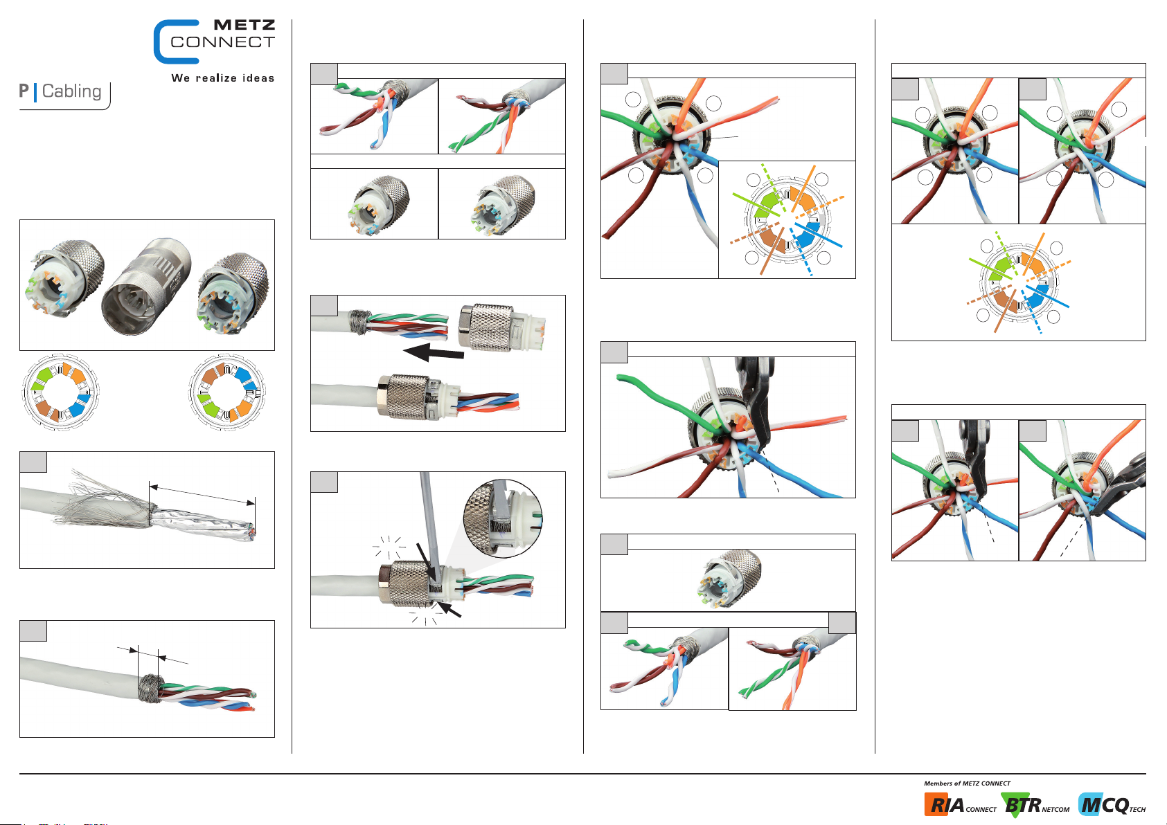
Cable connection for first cable end
white stuffer cap is selected
Cable connector Class F
AWG 24/1-22/1, AWG 24/7-22/7
130 8 6 3 - 02-E
Mounting information
Connector housing
white stuffer cap
grey stuffer cap
1
1.37 8
A
3
first cable end
white stuffer cap grey stuffer cap
7350/899316
Take that stuffer c ap that shows the s ame colo r coding as the wire
pairs of the cabl e.
If white s tuffer cap wa s sele ct: af ter ste p 4+5 go to step 6
If grey s tuffer cap was s elec t: after step 4+5 go to step 11
4
Inser t the cable into th e stuf fer cap until the br aid is at the same level
as the shield clamps.
5
6
2.
GN
BN-WH
1.
BN
Untwist the wire pairs. Start with pair brown an d inser t the wires
according to the color coding into the slots of th e stuf fer cap. When
inser ting the wires i t is essential to r espe ct the order:
1. brown, 2. gre en, 3. oran ge, 4. blue
7
Cut the wires flush with t he housing edge
white stuffer cap
GN-WH
BU-WH
white stuffer cap
OG
OG-WH
3.
guide slot
BU
4.
GN
BN-WH
GN-WH
2.
1.
BN
cut flus h
OG
3.
OG-WH
BU
4.
BU-WH
white stuffer cap
GN
2.
1.
OG
3.
4.
BU-WH
GN-WH
BN
OG-WH
BU
OG
3.
OG-WH
BU
4.
BU-WH
14a 15b
GN
BN-WH
Untwist the wire pairs. Start with pair brown an d inser t the wires
according to the color coding into the slots of th e stuf fer cap. When
inser ting the wires i t is essential to r espe ct the order:
1. brown, 2. gre en, 3. oran ge, 4. blue
GN-WH
2.
1.
BN
BN-WH
GN
3.
OG-WH
4.
BU-WH
2.
1.
OG
GN-WH
BN
BN-WH
BU
white stuffer cap
15a 15b
cut flus h
click
Remove about 1.378 inches of the p lastic sheath and fold braided
shield backwards.
2
0.19 7
Wrap the br aided shield evenly ar ound the s hield foil, cut and remove
the shield foil.
METZ CONNECT | Im Tal 2 | 78176 Blumberg | Germany | Phone +49 7702 533-0 | Fax +49 7702 533-433
Distributed by RIA CONNECT GmbH and BTR NETCOM GmbH
Mounting instruction see www.metz-connect.com
Take a small screwdri ver to press the 2 s hield clamps into t he clip
mechanism.
1.
click
2.
8
8a 8b
Repeat steps 1 and 2 as well as 4 and 5 to conn ect the second cable
end.
Note: Dependin g on the cable end a cr ossing of wire pairs blue and
green may be pos sible.
grey stuffer cap
second cable end
cut flus h
Cut the wires flush with t he housing edge
Page 4
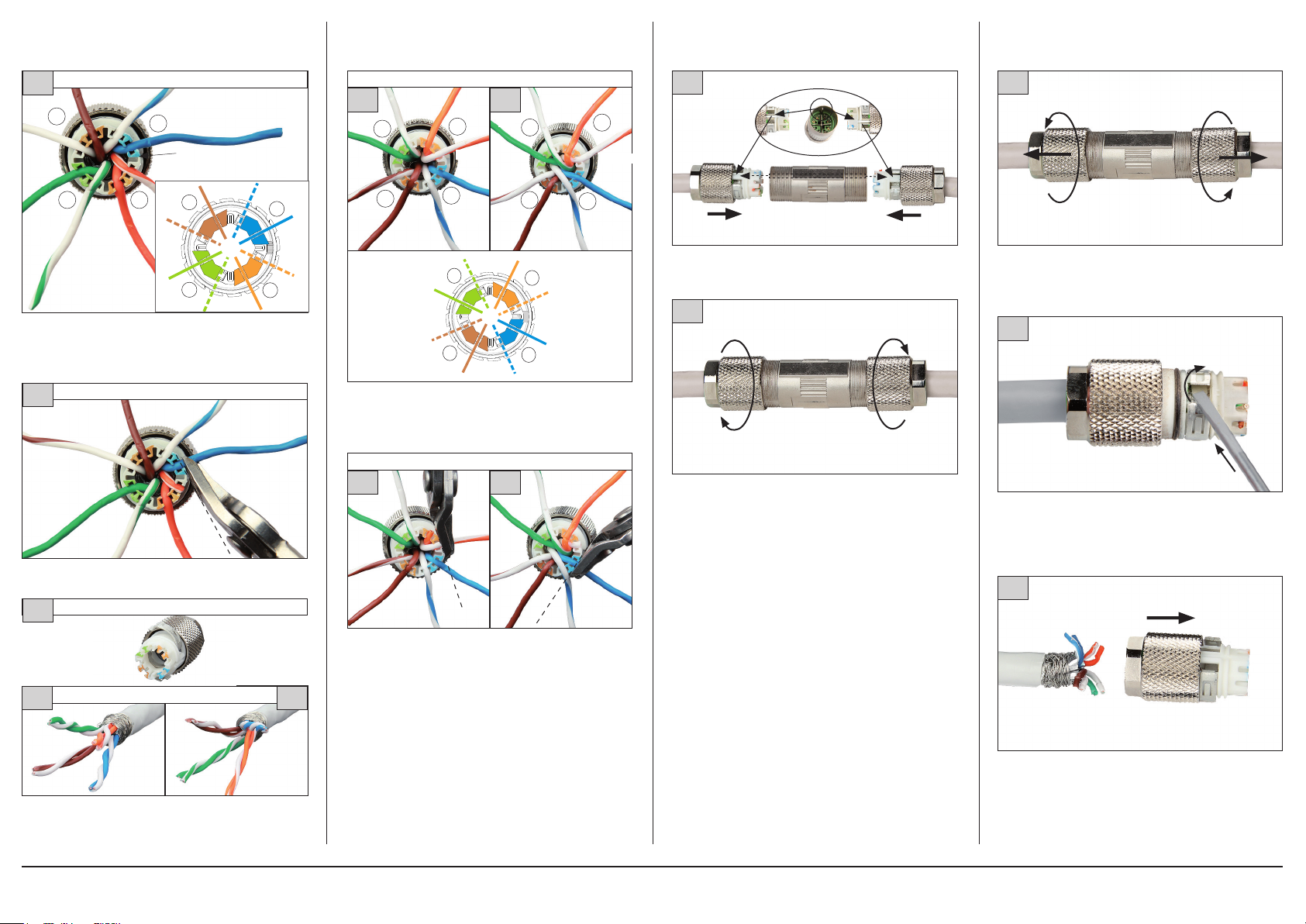
Cable connection for first cable end
grey stuffer cap is selected
Disassembly
11
1
BN-WH
GN
2.
GN-WH
Untwist the wire pairs. Start with pair brown and inser t the wires
according to the color coding into the slots of th e stuf fer cap. When
inser ting the wires i t is essential to r espe ct the order:
1. brown, 2. gre en, 3. oran ge, 4. blue
12
grey stuffer cap
BN
OG
grey stuffer cap
3.
4.
OG-WH
BN-WH
GN
GN-WH
BL- WS
BU
guide slot
BN
1.
2.
cut flus h
BU-WH
4.
OG-WH
3.
OG
BU
white stuffer cap
GN
2.
1.
OG
3.
4.
BU-WH
GN-WH
BN
OG-WH
BU
OG
3.
OG-WH
BU
4.
BU-WH
14a 15b
GN
BN-WH
Untwist the wire pairs. Start with pair brown an d inser t the wires
according to the color coding into the slots of th e stuf fer cap. When
inser ting the wires i t is essential to r espe ct the order:
1. brown, 2. gre en, 3. oran ge, 4. blue
GN-WH
2.
1.
BN
BN-WH
GN
3.
OG-WH
4.
BU-WH
2.
1.
OG
GN-WH
BN
BN-WH
BU
white stuffer cap
15a 15b
16
guide slot
When combining t he two parts a lign the guide slot of both stuffer
caps wi th the ridge of the co nnec tor housing...
guide slot
17
1 Nm
... and thightliy screw stu ffer c aps wit h connector housing.
Torque 1 Nm for s ecure c ontac t.
1 Nm
1
Unscre w stuf fer cap s from connector housing...
2
2.
1.
... and release the 2 shield clamps wi th a small s crewdriver...
Cut the wires flush with t he housing edge
13
13a 13b
Repeat steps 1 and 2 as well as 4 and 5 to conn ect the second cable
end.
Note: Dependin g on the cable end a cr ossing of wire pairs blue and
green may be pos sible.
METZ CONNECT | Im Tal 2 | 78176 Blumberg | Germany | Phone +49 7702 533-0 | Fax +49 7702 533-433
Distributed by RIA CONNECT GmbH and BTR NETCOM GmbH
Mounting instruction see www.metz-connect.com
white stuffer cap
Cut the wires flush with t he housing edge
second cable end
cut flus h
3
cut flus h
... and pull the cable s out of the stuf fer cap.
 Loading...