

Page 1
de
DEUTSCH
en
ENGLISH
fr
FRANÇAIS
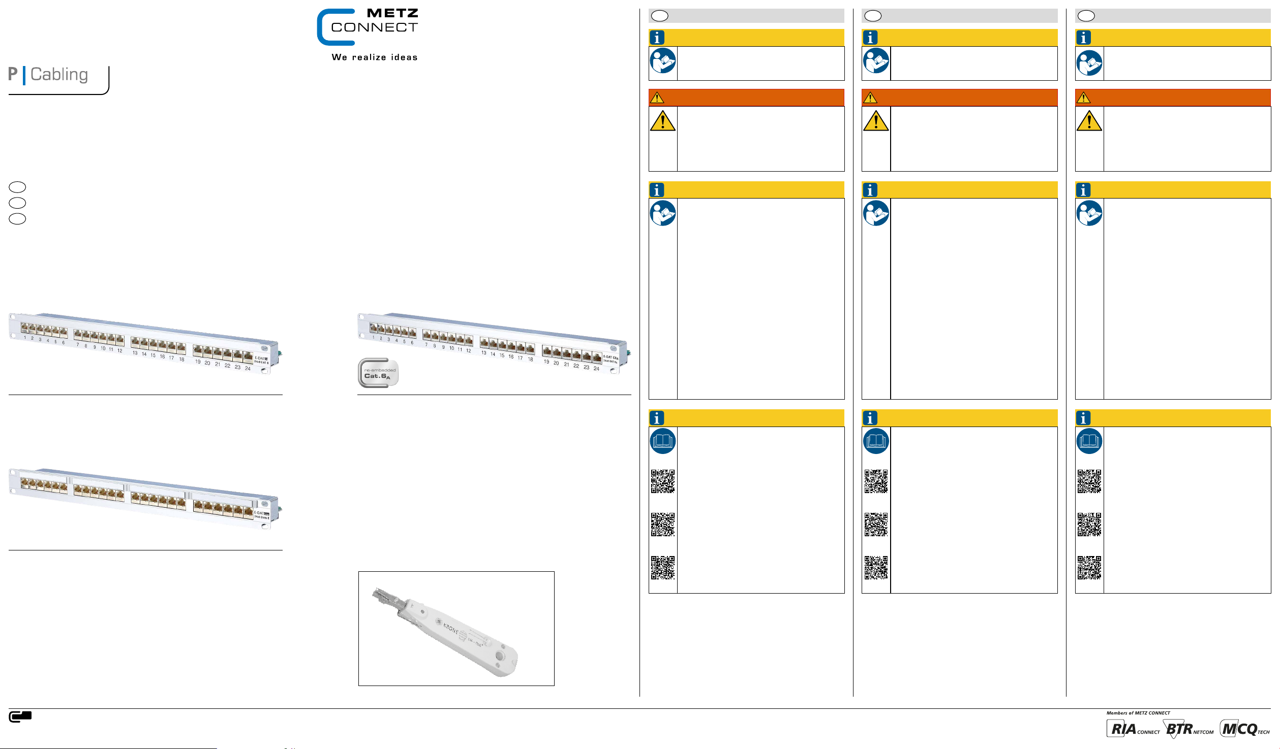
E-DAT kompakte Patchfelder
E-DAT compact Patch Panels
E-DAT Panneaux de brassage
Montagehinweis für den Installateur
de
Mounting note for the installer
en
Notice de montage pour l‘installateur
fr
E-DAT C6 24x8(8) 1HE LSA Cat.6 Patchfeld Class EA Link 500 MHz
E-DAT C6 24x8(8) 1RU LSA Cat.6 Patch Panel Class EA Link 500 MHz
E-DAT C6 panneau de brassage 24x8(8) 1UH LSA Cat.6 Classe EA Link 500MHz
130855-E
A000/899436
E-DAT C6A 24 Port 1HE LSA Cat.6A Patchfeld
E-DAT C6A 24 Port 1RU LSA Cat.6A Patch Panel
E-DAT C6A panneau de brassage 24 ports 1UH LSA Cat.6
130855C-E
HINWEIS
Anschlussfehler vermeiden!
Vor dem Anschluss Montageanleitung sorgfältig
lesen!
WARNUNG
Achtung!
Ausstecken (Ziehen des RJ45-Steckers) nur bei zuvor
ausgeschaltetem Gerät ohne Spannung. Ausstecken, insbesondere wiederholtes Ausstecken unter
Spannung (bei Verwendung von Power over Ethernet PoE) kann zu Schäden an den Kontakten der
RJ45-Steckverbindung führen.
HINWEIS
Unsere Anschlusssysteme und Verteilerprodukte für
strukturierte Gebäudeverkabelungen entsprechen den
gültigen Normen ISO/IEC 11801, EN 50173-1 und
IEC 60603-7. Bei Komplettierung der Anschlüsse muß
der Verwender/Mon tagebetrieb prüfen und beachten,
dass nur Patch- und Anschlusskabel, die die EN-/
IEC-Normen erfüllen, verwendet werden. Lassen Sie
sich ggf. vom Lieferanten den Nachweis geben, dass
A
die eingesetzten Kabel und Stecker der Norm entsprechen. Die Verwendung von nicht normgerechten
Komponenten bedeutet den Verlust der Mängelrechte
auch innerhalb der Lieferkette unserer Produkte. Die
Installation ist nur von Fachpersonal durchzuführen. Hierbei sind die Sicherheitsanforde rungen nach
EN 60950 zu beachten. Bitte beachten Sie auch,
dass keine starken mechanischen Ein wirkungen und
Bean spruchungen beim Ein- und Ausstecken des
Benutzerkabels nach oben, unten oder seitlich auf den
elektrischen Kontaktbe reich der Steckverbindung (z.
B. durch Ziehen am Kabel u. a.) erfolgen. Für dadurch
entstehende Schäden haften wir nicht. Bitte übergeben Sie diesen Hinweis auch an den Endverbraucher.
NOTE
Avoid connection errors!
Read mounting note carefully before connecting!
WARNING
Attention!
Before unplugging the RJ45 plug make sure that the
device is switched off and is no longer energised.
Unplugging, particularly repeated unplugging of an
energised device (when using Power over Ethernet
PoE) may damage the contacts of the R J45 plug
connection.
NOTE
Our termination systems and patch products for generic cabling meet the active standards ISO/IEC 11801,
EN 50173-1 und IEC 60603-7. The user or installer has
to check and take care to use solely patch and termination cables that meet the EN-/IEC standards when
completing the installation. If necessary ask your supplier to certify that the installed cables and plugs meet
the standards. The use of non-standard components
means the loss of rights accruing from defects even
within the supply chain of our products. Installation
only by qualified personnel. Electrical Safety per EN
60950. Furthermore, please pay attention that the
electric contact area of the plug connection is not
exposed to high mechanical effects or strain (e.g. by
pulling the cable etc.) when the user cable is plugged
in or out upwards, downwards or sidewards. We do
not take over liability for any damage. Please give this
note to end users, too.
NOTICE
Eviter des erreurs de raccordement !
A lire attentivement avant de procéder au
raccordement !
AVERTISSEMENT
Attention!
Débrancher la fiche RJ45 seulement après avoir
éteint l‘appareil et l‘avoir mis hors tension. Un
débranchement sous tension, surtout répété, peut
causer des dommages aux contacts de la connexion
RJ45 en cas d‘utilisation Power over Ethernet (PoE).
NOTICE
Nos systèmes de raccordement et produits de
distribution pour le câblage générique sont conformes aux normes en vigueur EN 50173-1:2007
et IEC 60603-7. Il est nécessaire que l’utilisateur
ou l’entreprise d’installation vérifient et tiennent
compte d’employer uniquement les cordons de
brassage et de raccordement qui répondent aux
normes EN/IEC. Il est conseillé de se faire certifier
cette conformité aux normes par le fournisseur
des câbles et connecteurs utilisés. L’utilisation
de composants qui ne sont pas conformes aux
normes ci-dessus entraînera la perte des droits de
réclamation aussi dans la chaîne de livraison de nos
produits. L’installation ne peut être effectuée par
des spécialistes en tenant compte des demandes de
sécurité selon EN 60950. Prière de faire attention
qu’il n’y a pas de forts actions et efforts agissant
vers le haut, vers le bas ou vers le côté dans la région électrique du contact du connecteur en insérant
ou en sortant le câble client (p. ex. en tirant sur le
câble). Nous n’assumons pas de responsabilité pour
des dégâts qui en résultent. Prière de donner ces
indications aussi à l’utilisateur final.
E-DAT design 24x8 Patchfeld Class E / Cat.6 Link bis 250MHz
E-DAT design 24x8 Patch Panel Class E / Cat.6 Link to 250MHz
E-DAT design panneau de brassage 24x8 Classe E / Cat.6 lien jusqu‘à 250 MHz
130853-E
Zubehör / Accessories / Accessoires
HINWEIS
Zusätzliche Informationen und weiterführende
Dokumentationen wie Datenblatt, stehen zum
Download unter w ww.metz-connect.com für Sie
bereit.
130 855-E
130 855C-E
130 853-E
NOTE
More detailed information and documentation
such as data sheet are available as download at
www.metz-connect.com
130 855-E
130 855C-E
130 853-E
NOTICE
Des informations et documentations supplémentaires comme la fiche technique, sont disponibles
pour téléchargement sur www.metz-connect.com
130 855-E
130 855C-E
130 853-E
Zubehör Accessories Accessoires
Das LSA PLUS® Anlegewerkzeug ist erhältlich unter der
Art.-Nr. 130818-E
The crimp tool LSA PLUS® is available with
P/N 130818-E
L‘outil de raccordement LSA PLUS® est en vente sous la
Réf.: 130818-E
METZ CONNECT GmbH | Im Tal 2 | 78176 Blumberg | Germany
Phone +49 7702 533-0 | Fax +49 7702 533-433
Weitere technische Dokumentationen siehe / For more technical documentation see / Plus de documentation technique à télécharger sur www.metz-connect.com
Page 2
A | Kabelkonfektion / Cable Preparation / Préparation du câble
de
DEUTSCH
en
ENGLISH
fr
FRANÇAIS
1 2
80 mm
70 mm
3a 3b
A
8
B
80 mm
Pair
WH-GN 1
GN 2 6
WH-BU 5
BU 4 4
WH-OG 3
OG 6 2
C
D
WH-BN 7
BN 8 8
B | Kabelmontage / Cable connection / Raccordement du câble
1
2
T568A T568B
Pin Length Pin Length
A = 12 mm
B = 22 mm
C = 36 mm
D = 46 mm
3
C = 36 mm
5
B = 22 mm
1
A = 12 mm
7
D = 46 mm
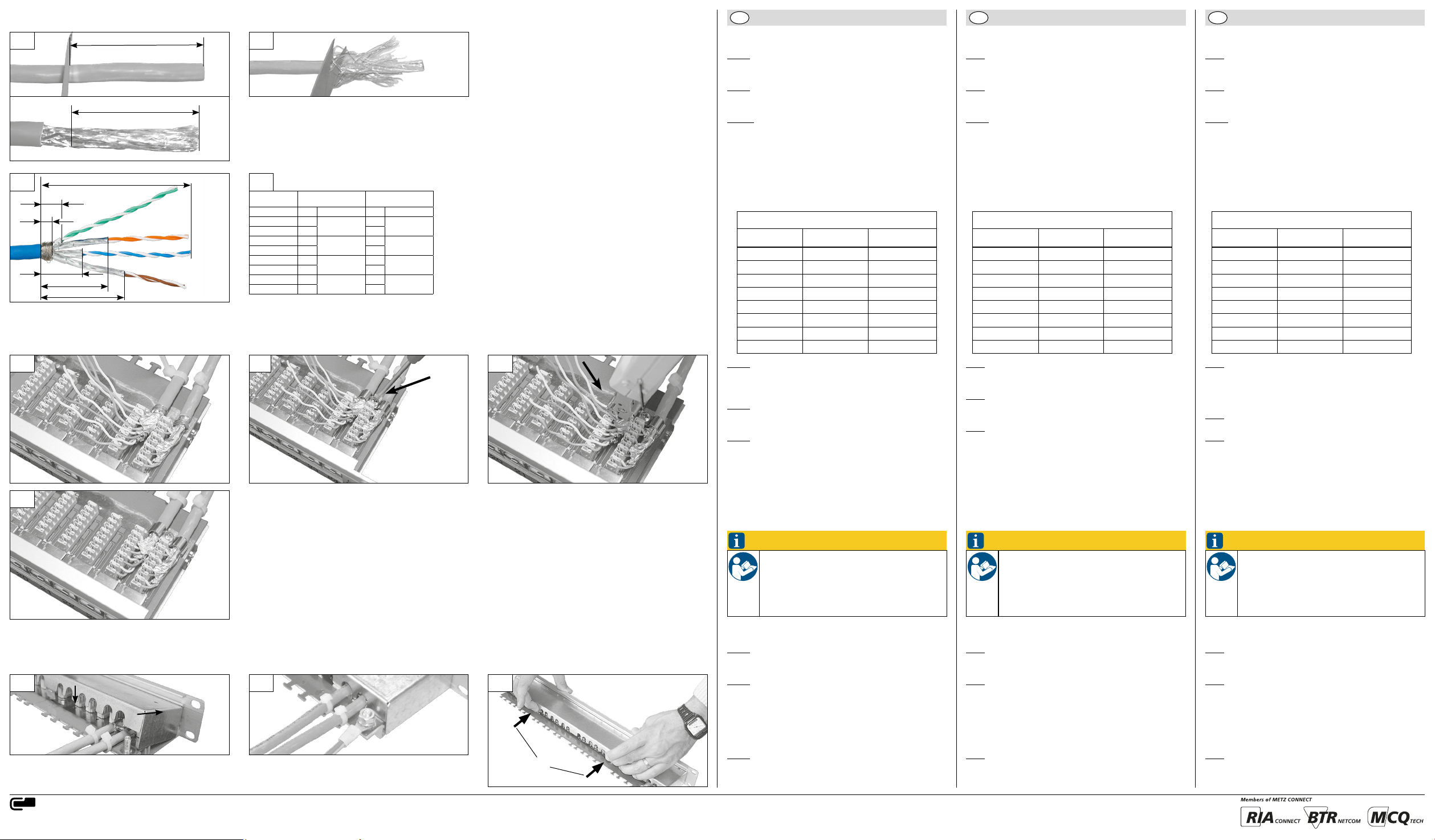
A | Kabelkonfektion
Abb. 1 Kunststoffmantel ca. 80 mm abisolieren. Schirmge flecht ablängen durch...
Abb. 2 ... Zurückschieben und rundherum abschneiden, und
um die Adern drehen.
Abb. 3a Adernpaare nach Farbe separieren und Schirmfolie
gemäß der Tabelle (Abb. 3b) ablängen.
B | Kabelmontage
Anschlussbelegung
PIN Nr. T568A T568B
1 WH-GN WH-OG
2 GN OG
3 WH-OG WH-GN
4 BU BU
5 WH-BU WH-BU
6 OG GN
7 WH-BN WH-BN
8 BN BN
3
Abb. 1 Zugentlastung mit Kabelbinder herstellen. Kabel binder nicht im Lieferumfang enthalten
(3,6 x 140 mm).
Abb. 2 Schirmanschlussschelle aufsetzen und
festschrauben.
Abb. 3 Kabel von Port 24/23 beginnend anschließen. Dabei
Paarverdrillung und Schirmfolie bis zur Klemme
vorführen. Adernpaare gemäß Tabelle „Anschluss belegung“ von Klemme 1/2 beginnend anschließen.
A | Cable Preparation A | Préparation du câble
Fig. 1 Remove about 80 mm of the plastic sheath. Cut the
braided shield to length...
Fig. 2 ... by pushing the shield back and cutting it off all
round and wrap it around.
Fig. 3a Cut the shield, separate the wire pairs and arrange
them according to color (Fig. 3b).
B | Cable connection
Pin assignment
PIN No. T568A T568B
1 WH-GN WH-OG
2 GN OG
3 WH-OG WH-GN
4 BU BU
5 WH-BU WH-BU
6 OG GN
7 WH-BN WH-BN
8 BN BN
Fig. 1 Use cable ties for strain relief. Cable ties are not
included to packing unit (3,6 x 140 mm).
Fig. 2 Attach the shield connection clamp and screw it
down.
Fig. 3 Connect the cables starting with ports 24/23.
Keep the wire pairs twisted and keep the shield foil
up to the contacts. Connect the wire pairs starting
with contacts 1/2 according to the chart „Pin
assignment“.
Fig. 1 Dénuder la gaine plastique d‘environ 80 mm.
Découper le blindage tressé ...
Fig. 2 ... en le reculant et le coupant tout autour, ensuite
l‘enrouler autour des fils.
Fig. 3a Couper le blindage en feuille et séparer les paires de
fils selon les couleurs (3b).
B | Raccordement du câble
Affectation des contacts
Contact no. T568A T568B
1 WH-GN WH-OG
2 GN OG
3 WH-OG WH-GN
4 BU BU
5 WH-BU WH-BU
6 OG GN
7 WH-BN WH-BN
8 BN BN
Fig. 1 Etablir la décharge de traction par collier. Une
décharge de traction supplémentaire est possible
par attaches-câbles. Des attaches-câbles ne sont pas
compris (3,6 x 140 mm).
Fig. 2 Poser le collier pour raccorder le blindage et le visser.
Fig. 3 Raccorder le câble en commençant au port 24/23,
laisser les paires torsadées jusqu‘au bornier.
Raccorder les paires de fils en connençant au
contact 1/2.
4
D | Öffnen der Geräteabdeckung
Opening of the Panel Cover
C | Endmontage / Final assembly / Montage final
1 2 1
Ë
Ouvrir le cache du panneau
Ê
METZ CONNECT GmbH | Im Tal 2 | 78176 Blumberg | Germany
Phone +49 7702 533-0 | Fax +49 7702 533-433
Weitere technische Dokumentationen siehe / For more technical documentation see / Plus de documentation technique à télécharger sur www.metz-connect.com
Ê
Ë
HINWEIS
Für Betrieb und Abnahmemessung
Geräteabdeckung muss aufgesetzt sein, wenn Gerät
in Betrieb ist oder die Abnahmemessung durchgeführt werden soll.
C | Endmontage
Abb. 1 Geräteabdeckung am Patchfeldrahmen ansetzen Ê
und nach unten einrasten Ë.
Abb. 2 Anschluss des Potentialausgleichs.
(Erdungsset liegt der Verpackung bei)
D | Öffnen der Geräteabdeckung
Abb. 1 Rasthaken leicht eindrücken Ê und die Geräteab deckung nach oben klappen Ë.
NOTE
For Operation and Acceptance
Measurement
The panel cover has to be put on for operation and
the acceptance measurement.
C | Final assembly
Fig. 1 Apply the cover to the patch panel frame Ê and
click it downwards into place Ë.
Fig. 2 Fit the earthing lead.
(an earthing kit is enclosed with each packing unit)
D | Opening of the Panel Cover
Fig. 1 Slightly push in the snap fits Ê and turn the cover
up Ë.
NOTICE
Avis impor tant
(pour le fonctionnement et la mesure de
réception)
Le cache du panneau doit être en place si l‘appareil
est en service ou si la mesure de réception est à
effectuée.
C | Montage final
Fig. 1 Enclencher le couvercle au cadre du panneau de
brassage Ê et l‘encliqueter vers le bas Ë.
Fig. 2 Raccorder la compensation de potentiel.
(Un kit de mise à la terre est inclus à l‘emballage)
D | Ouvrir le cache du panneau
Fig. 1 Enfoncer légèrement les brides de fixation Ê et le
relever vers le haut Ë.
 Loading...