

Page 1
Rapid
TV • VIDEO • CAMCORDER • MECABLITZ
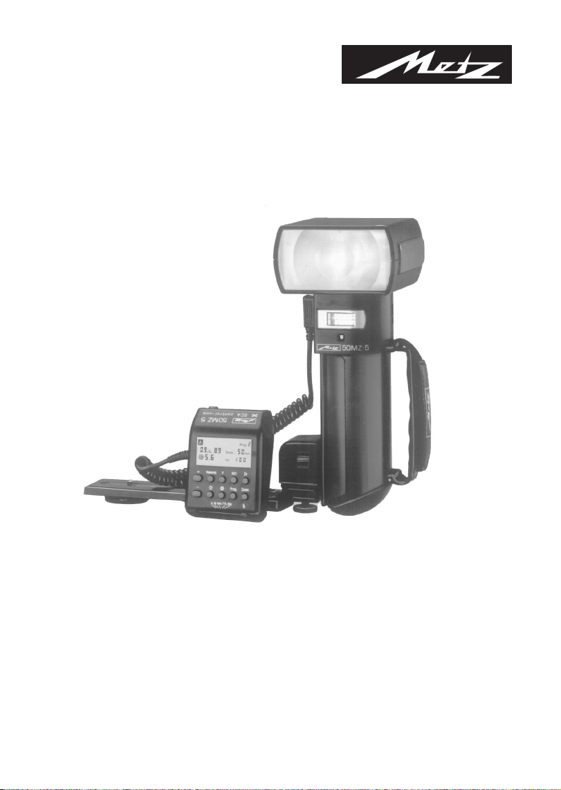
MECABLITZ 50 MZ-5
Operating Instructions
Page 2

Contents
Foreword . . . . . . . . . . . . . . . . . . . . . . . . . . . . . . . . . . . . . . . . . . . . . . . . . . . 4
1. Safety instructions . . . . . . . . . . . . . . . . . . . . . . . . . . . . . . . . . . . . . . . . . . . 6
2. Preparing the flashgun for use. . . . . . . . . . . . . . . . . . . . . . . . . . . . . . . . . . 7
2.1 Attaching the control unit and the flashgun to the camera . . . . . . . . . . . . . . . 7
2.2 Power supply and battery warning indicator . . . . . . . . . . . . . . . . . . . . . . . . . 8
2.3 Replacing and charging the battery . . . . . . . . . . . . . . . . . . . . . . . . . . . . . . . . 8
2.4 Switching the flashgun on and off . . . . . . . . . . . . . . . . . . . . . . . . . . . . . . . . . 9
3. TTL flash mode . . . . . . . . . . . . . . . . . . . . . . . . . . . . . . . . . . . . . . . . . . . . . 10
3.1 TTL Easy-Mode . . . . . . . . . . . . . . . . . . . . . . . . . . . . . . . . . . . . . . . . . . . . . . 10
4. Automatic flash mode. . . . . . . . . . . . . . . . . . . . . . . . . . . . . . . . . . . . . . . . 14
5. Manual flash mode . . . . . . . . . . . . . . . . . . . . . . . . . . . . . . . . . . . . . . . . . . 16
6. Bounced flash . . . . . . . . . . . . . . . . . . . . . . . . . . . . . . . . . . . . . . . . . . . . . . 18
6.1 Bounced flash with secondary reflector switched on . . . . . . . . . . . . . . . . . . 19
6.2 Bounced flash in automatic and TTL flash modes . . . . . . . . . . . . . . . . . . . . 19
6.3 Bounced flash in manual flash mode. . . . . . . . . . . . . . . . . . . . . . . . . . . . . . 19
7. Cordless remote control mode . . . . . . . . . . . . . . . . . . . . . . . . . . . . . . . . . 20
7.1 Cordless Metz TTL remote control mode . . . . . . . . . . . . . . . . . . . . . . . . . . . 22
7.2 Cordless Metz automatic remote control mode . . . . . . . . . . . . . . . . . . . . . . 24
8. Winder mode . . . . . . . . . . . . . . . . . . . . . . . . . . . . . . . . . . . . . . . . . . . . . . . 25
8.1 Using the winder facility in manual flash mode . . . . . . . . . . . . . . . . . . . . . . 25
8.2 Using the winder facility in automatic and TTL flash mode. . . . . . . . . . . . . . 25
9. Working with partial light output levels. . . . . . . . . . . . . . . . . . . . . . . . . . 26
9.1 Partial light output levels in automatic flash mode. . . . . . . . . . . . . . . . . . . . 26
9.2 Partial light output levels in manual flash mode . . . . . . . . . . . . . . . . . . . . . 26
9.3 Macrophotography (close-ups) . . . . . . . . . . . . . . . . . . . . . . . . . . . . . . . . . . 26
10. Stroboscopic flash mode . . . . . . . . . . . . . . . . . . . . . . . . . . . . . . . . . . . . . 28
11. Fill-in flash in daylight . . . . . . . . . . . . . . . . . . . . . . . . . . . . . . . . . . . . . . . 30
11.1 Fill-in flash in automatic mode . . . . . . . . . . . . . . . . . . . . . . . . . . . . . . . . . . 30
11.2 Fill-in flash in manual mode . . . . . . . . . . . . . . . . . . . . . . . . . . . . . . . . . . . . 31
11.3 Fill-in flash in TTL mode . . . . . . . . . . . . . . . . . . . . . . . . . . . . . . . . . . . . . . . 31
12. Working with user programs . . . . . . . . . . . . . . . . . . . . . . . . . . . . . . . . . . 32
13. Special functions . . . . . . . . . . . . . . . . . . . . . . . . . . . . . . . . . . . . . . . . . . . 34
13.1 AF measuring beam . . . . . . . . . . . . . . . . . . . . . . . . . . . . . . . . . . . . . . . . . . 34
13.2 Auto-check display . . . . . . . . . . . . . . . . . . . . . . . . . . . . . . . . . . . . . . . . . . . 34
13.3 Warning displays and audible warning signals. . . . . . . . . . . . . . . . . . . . . . . 35
13.4 The buzzer . . . . . . . . . . . . . . . . . . . . . . . . . . . . . . . . . . . . . . . . . . . . . . . . . 36
13.5 Locking the controls . . . . . . . . . . . . . . . . . . . . . . . . . . . . . . . . . . . . . . . . . . 38
13.6 Changing over the distance dimension . . . . . . . . . . . . . . . . . . . . . . . . . . . . 38
13.7 The zoom reflector . . . . . . . . . . . . . . . . . . . . . . . . . . . . . . . . . . . . . . . . . . . 39
2
Page 3

Contents
13.7.1 The Ex-Zoom mode (extended zoom) . . . . . . . . . . . . . . . . . . . . . . . . . . . . . 39
13.8 The „Rapid“ function. . . . . . . . . . . . . . . . . . . . . . . . . . . . . . . . . . . . . . . . . . 40
13.9 The ML function (modelling light) . . . . . . . . . . . . . . . . . . . . . . . . . . . . . . . . 40
14. Exposure corrections . . . . . . . . . . . . . . . . . . . . . . . . . . . . . . . . . . . . . . . . 41
14.1 Exposure correction in automatic flash mode . . . . . . . . . . . . . . . . . . . . . . . 41
14.2 Exposure correction in TTL flash mode . . . . . . . . . . . . . . . . . . . . . . . . . . . . 41
15. Parallax compensation . . . . . . . . . . . . . . . . . . . . . . . . . . . . . . . . . . . . . . . 42
16. Trouble-shooting hints . . . . . . . . . . . . . . . . . . . . . . . . . . . . . . . . . . . . . . . 43
17. Care and maintenance . . . . . . . . . . . . . . . . . . . . . . . . . . . . . . . . . . . . . . . 43
18. Technical data. . . . . . . . . . . . . . . . . . . . . . . . . . . . . . . . . . . . . . . . . . . . . . 44
19. Special accessories . . . . . . . . . . . . . . . . . . . . . . . . . . . . . . . . . . . . . . . . . 52
Index . . . . . . . . . . . . . . . . . . . . . . . . . . . . . . . . . . . . . . . . . . . . . . . . . . . . . 53
3
Page 4

Foreword and general instructions
Congratulations on purchasing this Metz flashgun, and thank you for your confidence in Metz
equipment.
It is only natural that you should want to use your flashgun straight away. However, it will be
well worth your while to study these Operating Instructions beforehand to ensure that you can
operate the flashgun effectively and without any problems.
Please also open the back cover page with the illustrations.
This flashgun can be used with:
• All cameras with a hot shoe
• All cameras with accessory shoe without hot-shoe contact, and with a synchronizing cable
• System cameras
Optimal adaptation to your camera is achieved by using an SCA adapter. The enclosed
SCA 300/3000 table will indicate the adapter you require for your particular camera model. This
table also indicates the special flash functions that can then be completed by the given system.
Brief survey of the operating functions:
Configuration
• 50 MZ-5 with 301 standard base: Automatic flash mode, ch. 4, p. 14
• 50 MZ-5 with SCA 300 adapter: Automatic flash mode, ch. 4, p. 14
• 50 MZ-5 with SCA 3000 adapter: Automatic flash mode, ch. 4, p. 14
The SCA 3000 adapter is the most convenient link to your camera! The ISO, zoom and aperture
data are transmitted, depending upon the camera configuration!
Operating modes possible
Manual flash mode, ch. 5, p. 16
Metz automatic remote control, ch. 7.2, p. 24
Stroboscopic mode, ch. 10, p. 28
TTL flash mode*, ch. 3, p. 10
TTL Easy Mode*, ch. 3.1, p. 10
Manual flash mode, ch. 5, p. 16
Metz TTL remote mode*, ch. 7.1, p. 22
Metz automatic remote mode, ch. 7.2. p. 24
Stroboscopic mode, ch. 10, p. 28
*If the camera performs this function.
TTL flash mode*, ch. 3, p. 10
TTL Easy Mode, ch. 3.1, p. 10
Manual flash mode, ch. 5, p. 16
Metz TTL remote mode, ch. 7.1, p. 22
Metz automatic remote mode, ch. 7.2. p. 24
Stroboscopic mode, ch. 10, p. 28
4
Page 5

Foreword and general instructions
General operating instructions
The subsequent instructions are of a general nature. The procedures identified by red numbers
must be completed when using a system camera in conjunction with an SCA 3000 adapter.
steps identified by red numbers and • are completed with the 301 standard base.
All
All steps identified with an asterisk * must be additionally adjusted, depending upon the given
type of camera.
When manual settings are necessary on the control unit it is always first necessary to press the
corresponding button assigned to the given function. The symbol of the selected function will
flash for approx. 5 seconds. The value of the function has to be changed with the + buttons
during these 5 seconds, otherwise the existing value will be retained
.Example: The zoom setting is to be changed.
1.Press the manual zoom control button (32) - Zoom will flash for approx. 5
seconds.
2. As long as zoom is flashing press the + button (24) to raise the value, e.g. from
50 to 70. Zoom stops flashing after 5 seconds and the changed value is stored.
NOTE: These instructions show illustrations of the LC display. The distances indicated in
these illustrations are only examples and not binding!
5
Page 6

1. Safety Instructions
• NEVER fire a flash in the immediate vicinity of the eyes!
Flash fired directly in front of the eyes of a person or animal can damage the retina
and lead to severe visual disorders - even blindness!
• Never open or short-circuit rechargeable batteries!
• Do not expose batteries to excessive heat, for instance sunshine, etc.!
• Never throw exhausted batteries on a fire!
• Do not expose the flash unit and charger to dripping and splashing water!
• Protect the flashgun against excessive heat and humidity! Do not store the flashgun in
the glove compartment of a car!
• Never cover the ventilation slots and intake openings on the flashgun!
A built-in cooling fan is automatically switched on when the temperature inside the
flashgun exceeds 40°C.
• As a result of the high light energy of a series of flashes shot with full light output in
quick succession, the diffuser becomes intensely heated in zoom positions of 35 mm
and less. In such an event the flash recycling time is automatically extended in order
to protect the mecablitz against overheating.
• Never place material that is impervious to light in front of, or directly on, the reflector
screen. The reflector screen must be perfectly clean when a flash is fired. The high
energy of the flash light will burn the material or damage the reflector screen if this is
not observed!
• NEVER dismantle the flashgun! DANGER: HIGH VOLTAGE!
There are no components inside the flashgun that can be repaired by a layperson.
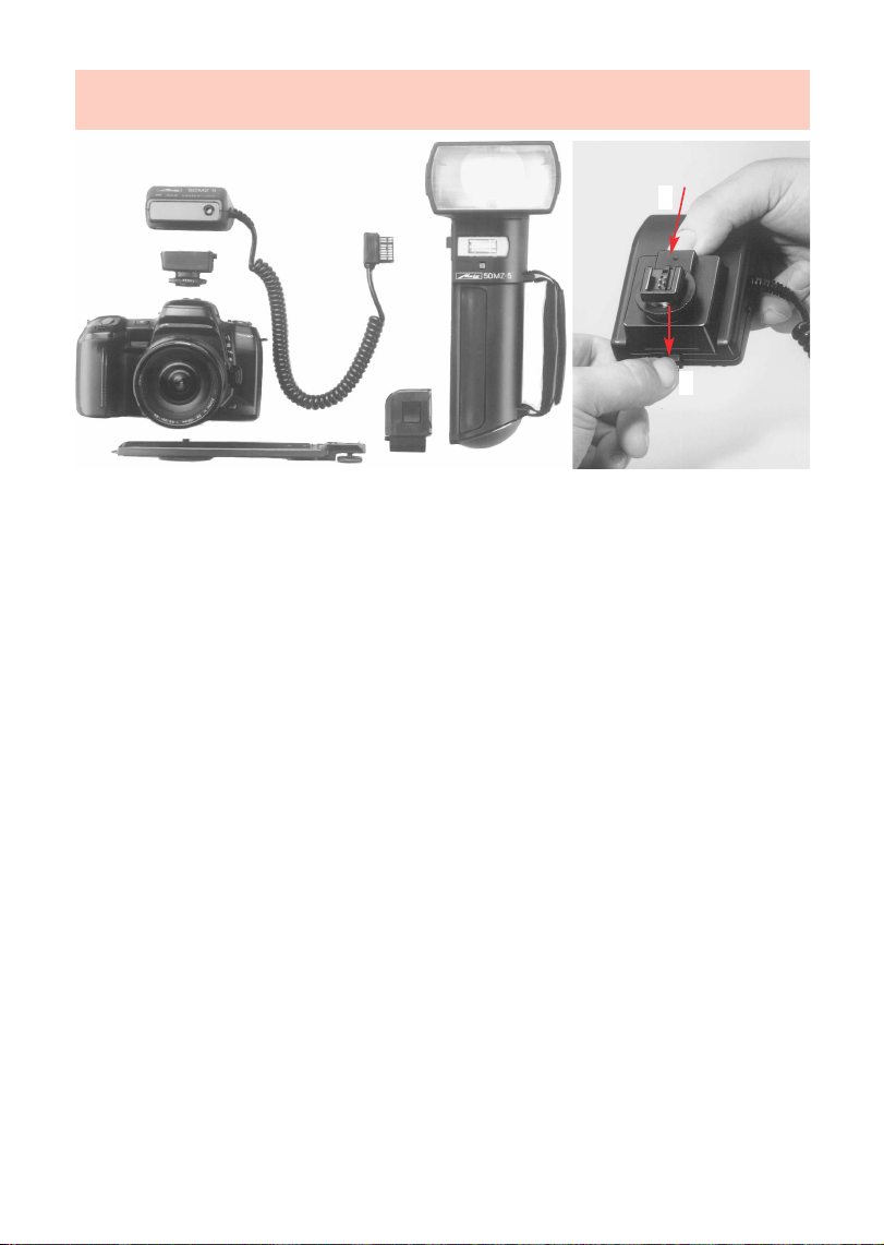
• To remove the control unit’s cable, press the gray
release button against the cable’s plug while
pulling out the cable.
➩
6
➮
Page 7
2. Preparing the flashgun for use
2
1
Fig. 1: Mounting the components, and removing the standard base or SCA adapter
2.1 Attaching the control unit and the flashgun to the camera
The control unit can only be mounted on the camera with the 301 standard base (5) or with
an SCA-300 or SCA-3000 adapter (Special Accessories).
Always switch off the camera and the flashgun before mounting or removing the
☞
flashgun. The red-light adapters (see also ch. 7, p. 20) of the SCA 300 System, as
well as the SCA 356 and the TTL Multiconnector SCA 305 A, can only be used if the
SCA 300 D spacer is mounted between the adapter and the control unit.
Push the control unit, with attached adapter or 301 standard base, into the camera’s accessory shoe
and clamp into position with the knurled nut (6). Insert the plug of the control unit’s cable into the
flashgun’s handle.The control unit is fitted with the 301 standard base for simple flash synchronization.
Mounting the flashgun:
• Fasten the camera bracket (8) with the bracket screw (7) to the camera’s tripod bush.
• Press the unlocking catch (14) on the Nicad battery, and turn the battery cover (10) anti-
clockwise until the 1st lock-in position is reached.
• Insert the holder block of the camera bracket into the guiding groove of the flashgun.
• Fasten the holder block with the locking screw (9).
• Turn the battery cover (10) clockwise until it is once again locked. The rectangular projection
then covers the opening of the guiding groove.
Removing the control unit, the standard base or the SCA adapter:
To remove the control unit’s cable, press the gray release button against the
☞
cable’s plug while pulling out the cable.
1 Push the locking lug upwards towards the control unit.
2 Remove the standard base or SCA adapter
7
Page 8
2. Preparing the flashgun for use
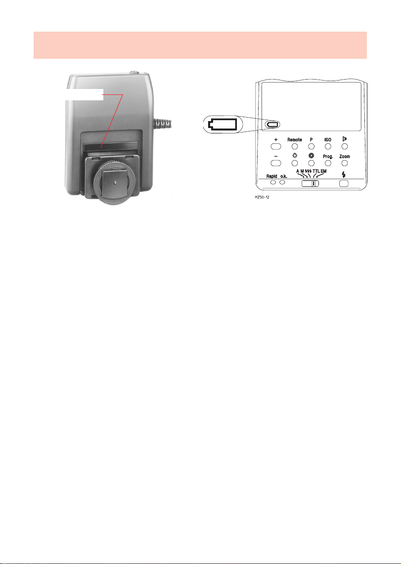
battery cover
Fig. 2a: Battery cover Fig. 2b: Battery warning indicator
Attaching the standard base or SCA adapter:
• Take hold of the battery cover (fig. 2a, only when using the SCA 3000 adapter) in the middle
and unclip.
• Push in the SCA adapter or the 301 standard base all the way in.
The control unit is automatically synchronized with the camera when it is inserted in the
camera’s accessory shoe.
Synchronization of cameras without hot shoe is possible with a synch cable (36-50, short or
36-51. 1 m long, Special Accessories) in the socket of the 301 standard base.
2.2 Power supply and battery warning indicator
The flashgun can only be operated with a Metz NiCad Battery Pack 50-40 or the Power Pack
P 50 (optional accessory). A charger for the Metz battery pack is supplied with the flashgun.
The battery warning light only comes on when the Battery Pack 50-40 is being used. The
operating light (17) in the handle starts flashing when the battery is exhausted, and the battery
warning light on the LC display becomes illuminated.
The flashing battery symbol (fig. 2b) on the LC display indicates that the Nicad
☞
battery is almost exhausted.
Spent batteries must not be thrown into the dustbin! Contribute to the protection
☞
of the environment and discard spent batteries at the appropriate disposal points!
2.3 Replacing and charging the battery
• Switch off the flashgun with the main switch (16).
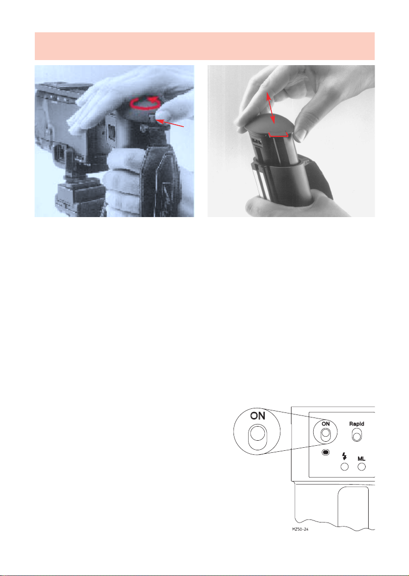
• Press the unlocking catch (14) on the Nicad battery; turn the battery cover (10) by 45° anticlockwise until it becomes audibly disengaged at the 2nd lock-in position, and remove.
8
Page 9
2. Preparing the flashgun for use
Fig. 3: Unlocking and inserting the battery
•
Connect the charger to the charging socket of the NiCad battery, and then plug into the mains.
- The charger's timer is switched on when the device is plugged into the mains.
- The red LED remains illuminated all the while the battery is being charged.
- After approx. 6 hours the charger is switched over to trickle charging.
- A flashing red LED (4 sec. "ON", 20 sec. "OFF") indicates that the battery is in trickle
charge mode and is ready for operation.
• Turn the battery cover (10) anti-clockwise until the 2nd lock-in position is reached before the
battery is returned to the handle.
• For insertion the battery’s charging socket must be inside the extension of the aluminium rail
of the handle.
• After insertion turn the battery cover clockwise and lock in position.
To identify an exhausted battery: Turn the battery cover clockwise until the stop point is
reached.
To identify a newly charged battery: Turn the battery cover anti-clockwise until the stop point
is reached.
2.4 Switching the flashgun ON and OFF
The flashgun is switched on with the main switch
(16). The flashgun is permanently on in the ON
position, and the operating light (17) shines. Push
the main switch (16) to the lower position to switch
off.
9
Page 10
3. TTL flash mode
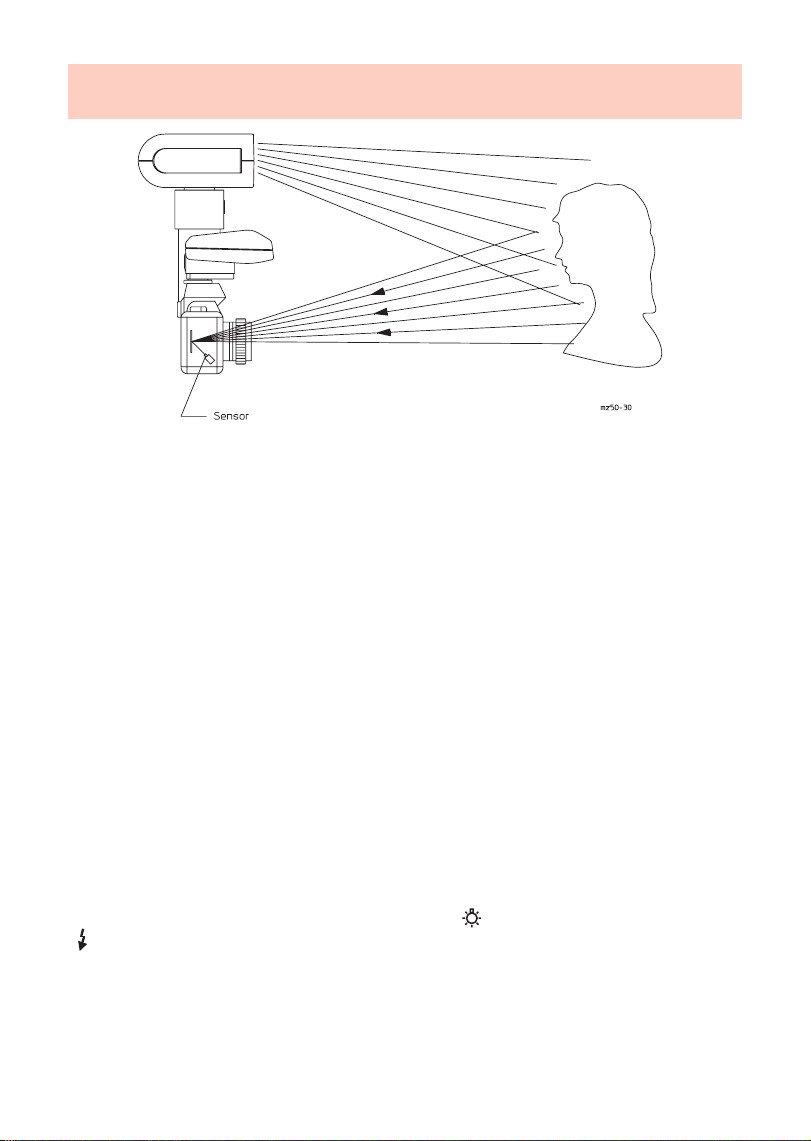
Fig. 4: Measuring method for TTL mode
Perfect flash exposures can be shot in a simple manner in the TTL mode.
The exposure readings in TTL mode are made by the sensor built into the camera (fig. 4). This
sensor measures the light reaching the film through the camera lens. As soon as the film has
been exposed by the correct amount of light an electronic control circuit within the camera
transmits a stop signal to the control unit, and the flash is instantly cut out.
The advantage of this flash mode is that all factors influencing the exposure of the film (filters,
change of aperture and focal length with zoom lenses, extensions for close-ups, etc.) are
automatically taken into account.
The mecablitz 50 MZ-5 offers two TTL flash modes: the TTL Mode and the TTL Easy Mode.
The TTL flash mode is only possible with cameras that feature this function. The
☞
control unit must be fitted with a corresponding SCA adapter (see „SCA 3000
System“ instructions and SCA survey table) for this purpose.
A film must be loaded in the camera to test the TTL functions.
Exposure corrections may be necessary with pronounced differences in contrast,
☞
for instance dark objects in snow (see ch. 14, p. 41).
3.1 TTL Easy flash mode (EM = Easy Mode)
This is the simplest way to operate the mecablitz in TTL flash mode. All buttons on the control
unit are locked, with the exception of the LCD light (27) and the manual firing button
(35).
In TTL Easy-Mode with the SCA 300 adapter, the zoom position is constantly adjusted to 28 mm to
ensure that the subject is always adequately illuminated.
In TTL Easy-Mode with the SCA 3000 adapter, the zoom setting is matched to the focal length of the
lens, and the distance range is indicated, provided that the camera supplies the zoom information.
10
Page 11
3. TTL flash mode
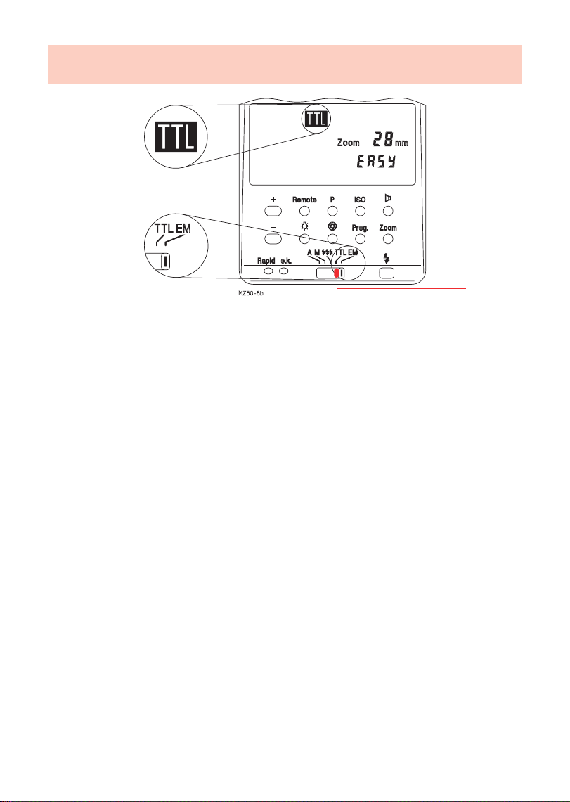
Fig. 5: Adjusting procedure for TTL Easy-Mode
We recommend the TTL Easy-Mode when using an SCA 300 adapter. Distance
☞
indication in the LC display is not possible in this mode.
Adjusting procedure for TTL Easy-Mode:
• Adjust the camera according to the manufacturer’s operating instructions.
• Fit the control unit (2) to the corresponding SCA adapter, and mount on the camera.
• Switch on the flashgun with the main switch (16).
1 Adjust the operating mode selector (28) to EM.
1
11
Page 12
3. TTL flash mode
1
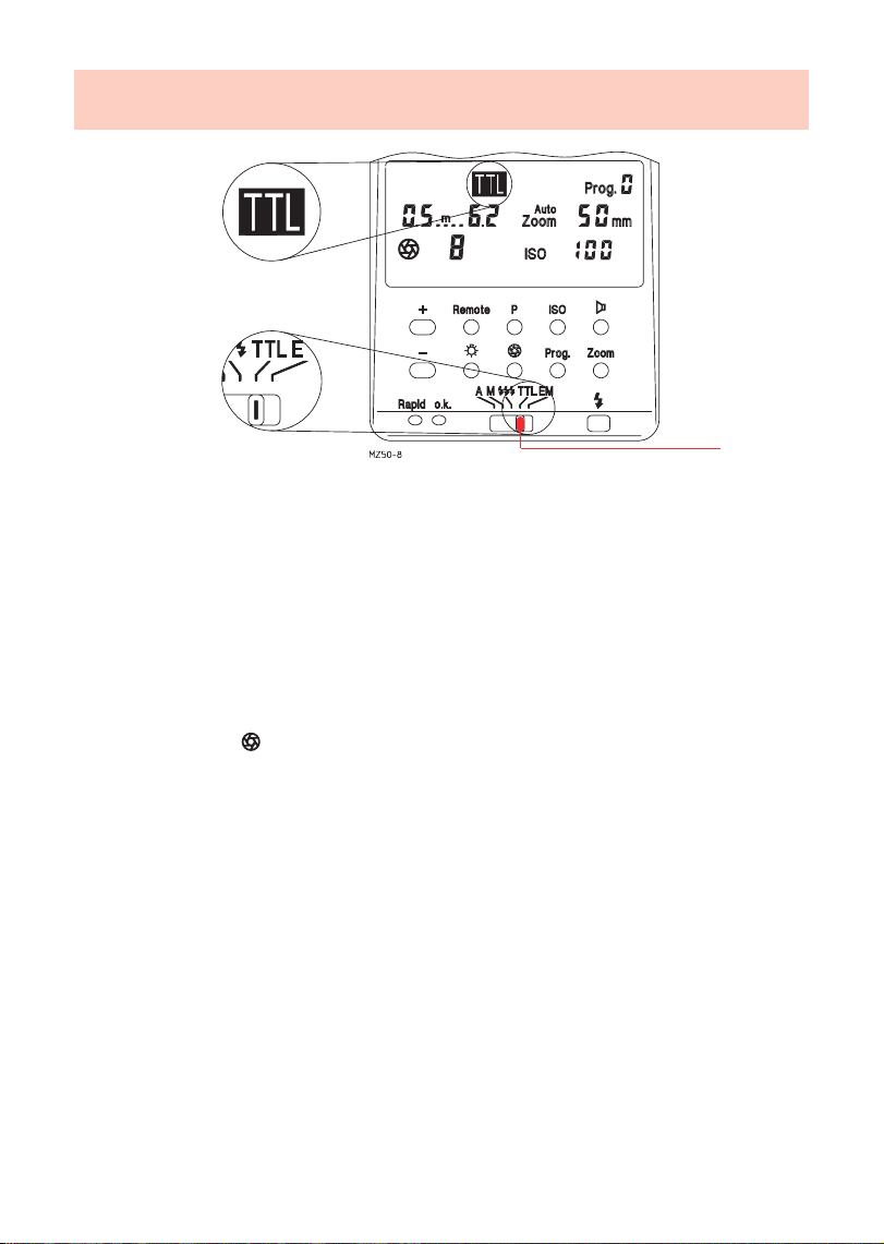
Fig. 6: Adjusting procedure for TTL flash mode
Adjusting procedure for TTL flash mode:
• Adjust the camera according to the manufacturer’s operating instructions.
• Fit the control unit to the corresponding SCA adapter, and mount on the camera.
• Switch on the flashgun with the main switch (16).
1 Adjust the operating mode selector (28) to TTL.
• *Press the ISO button (30), and adjust the film speed with the + or - button (24).
• *Press the Zoom button (32), and adjust with the + or - button (24) the zoom value that was
selected for the camera’s lens.
• *Press the button (34), and use the + or - button (24) to adjust the aperture until the
subject is located in the middle third of the indicated distance range. Set the resulting
aperture also on the camera.
• If required press button P (29), and adjust the partial light output with the + or - button (24)
(for Winder Mode see ch. 8, p. 25).
* Must be additionally adjusted on some cameras.
On some cameras the data for ISO and aperture are transferred to the control unit
☞
by way of the SCA 3000 adapter and cannot be changed manually.
12
Page 13

Notes
13
Page 14
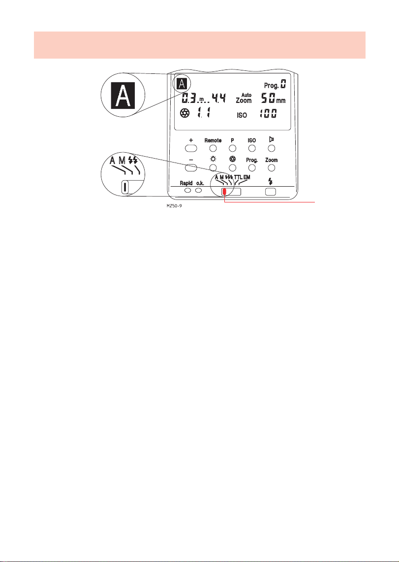
4. Automatic flash mode
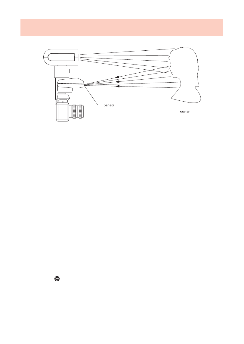
Fig. 7: Measuring procedure for automatic flash mode
In the automatic flash mode the sensor (4) of the control unit measures the light reflected from
the subject. The flash is cut off as soon as sufficient light has been emitted for a correct
exposure.
In this manner there is no need to calculate and adjust a new aperture when the distance is
changed, provided that the subject remains within the indicated automatic flash range.
The sensor (4) of the control unit must be directed at the subject, regardless of the direction at
which the main reflector (1) is pointing. The sensor has a measuring angle of approx. 25°, and
it only measures the light emitted by the attached flashgun.
Partial light output levels can also be adjusted in automatic flash mode (see ch. 9.1, p. 26).
Between six and twelve working apertures are available in the automatic flash mode,
depending upon the adjusted ISO film speed (Table 2 of the Technical Data).
Adjusting procedure for automatic exposure control:
• Adjust the camera according to the manufacturer’s operating instructions.
• Switch on the flashgun with the main switch (16).
1Adjust the operating mode selector (28) to A.
• *Press the ISO film speed button (30), and adjust the film speed with the + or - button (24).
• *Press the Zoom button (32), and adjust with the + or - button (24) the zoom value that
was selected for the camera’s lens.
• Press button (34), and use the + or - button (24) to adjust the aperture until the subject
is located in the middle third of the indicated distance range. Set the resulting aperture also
on the camera.
• If required press button P (29), and adjust the partial light output with the + or - button (24)
(see ch. 9, p. 26)
* Must be additionally adjusted on some cameras.
14
Page 15
4. Automatic flash mode
1
Fig. 8: Adjusting procedure for automatic flash mode
Some cameras automatically transmit the ISO, aperture and zoom values to the
☞
control unit also in the auto flash mode if an SCA 3000 adapter is used. No
settings have to be adjusted on the control unit where this is the case.
The permissible distance range and the corresponding aperture appear on the LC display.
The subject should be located within the middle third of this distance range as
☞
this gives the electronic control sufficient scope for compensation should this be
necessary.
There is a certain measure of overlap between the individual working apertures. As a result of
this overlap it is always possible to place the subject within the middle third of the range.
CAUTION with zoom lenses!
☞
Due to their design they can cause a loss of light in the order of up to one f-stop.
Furthermore, the effective aperture can also vary, depending upon the adjusted
focal length. This must be compensated by manually correcting the aperture
setting on the control unit!
15
Page 16
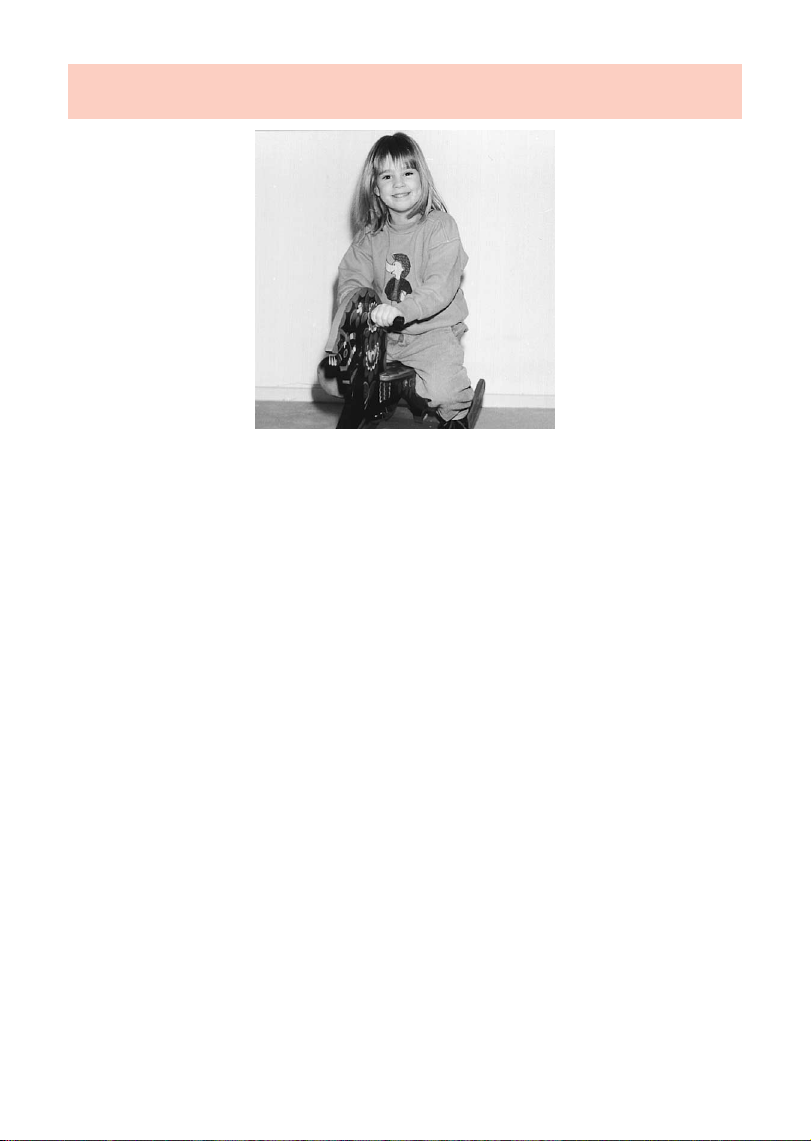
5. Manual flash mode
Fig. 9: Shot with direct flash light
In this mode the flashgun will emit its full power, provided that partial light output has not been
adjusted.
Adaptation to the picture shooting situation is by setting the corresponding aperture on the
camera.
A single value for the flash-to-subject distance appears on the LC display while in manual flash
mode.
If the displayed value does not coincide with the actual distance, then the aperture and/or
partial light output level have to be changed accordingly (see ch. 9.2, p. 26).
The decisive points for partial light output are:
• The distance to the subject
• The required aperture
• The ISO film speed
• The zoom setting of the reflector
The fine scaling of the partial light output levels ensures that the flash-to-subject
☞
distance can be adjusted in very small increments.
16
Page 17
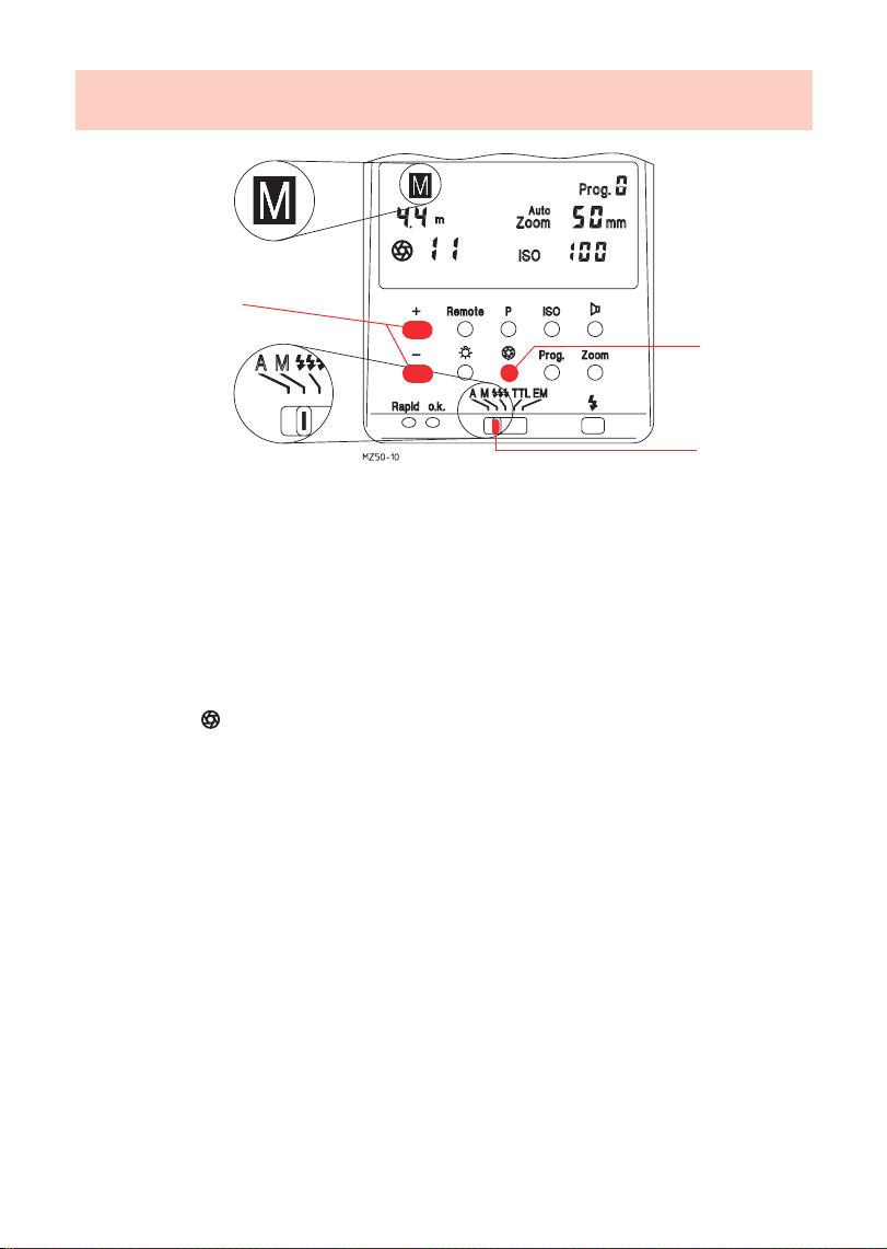
5. Manual flash mode
3
2
1
Fig. 10: Adjusting procedure for manual flash mode
Adjusting procedure for the manual flash mode:
• Adjust the camera according to the manufacturer’s operating instructions.
• Switch on the flashgun with the main switch (16).
1 Adjust the operating mode selector (28) to M.
• *Press the ISO button (30), and adjust the film speed with the + or - button (24).
• *Press the Zoom button (32), and adjust with the + or - button (24) the zoom value that
was selected for the camera’s lens.
2 Press button (34)
3Change the aperture on the flashgun with the + or - button (24) so that the required
distance is indicated on the LC display. Adjust this aperture value also on the camera.
• If required, press button P (29), and adjust the partial light output with the + or - button
(24) (see ch. 9, p. 26).
Some cameras automatically transmit the aperture, ISO and zoom values if an SCA
☞
3000 adapter is used. In such a case the aperture on the camera must be
continuously changed until the required distance is indicated on the LC display of
the control unit.
* Must be additionally adjusted on some cameras.
17
Page 18

6. Bounced flash
Fig. 11: Bounced flash (The photo was shot with the flash bounced off the right-hand wall)
Photos shot with full frontal flash are easily recognized by their harsh, dense shadows. This is
often associated with a sharp drop of light from the foreground to the background.
This phenomenon can be avoided with bounced flash because the diffused light will produce
a soft and uniform rendition of both the subject and the background. For this purpose the main
reflector (1) is turned in such a manner that the flash is bounced off a suitable reflective surface
(e.g. ceiling or walls of a room).
For this reason the reflector can be turned vertically and horizontally. The vertical lock-in
positions for bounced flash are:
• 60°, 75° and 90° (simply tilt the reflector to the required angle)
The head can be swivelled horizontally by 270°, and locks into position at 90° and 180°.
The distance values on the LC display disappear as soon as the reflector is tilted
☞
upwards or turned horizontally. This is because the spatial conditions and degree
of reflection do not allow the specification of definite distances.
When swivelling the main reflector (1) it is essential to ensure that it is turned by a sufficiently
wide angle so that direct light can no longer fall on the subject. Therefore, always swivel the
reflector to at least the first lock-in position.
The diffused light bounced back from the reflective surfaces results in a soft illumination of the
subject.
The reflecting surface must be white or have a neutral colour and it must not be structured (e.g.
wooden beams in the ceiling) as this could cast shadows. For colour effects just select
reflective surfaces in the required colour.
Use of the secondary reflector (11) is advantageous to avoid disturbing dense shadows with
bounced flash, for instance under the eyes and nose with portraits.
18
Page 19

6. Bounced flash
Fig. 12: Bouncing the flash with switched-on secondary reflector
6.1 Bounced flash with secondary reflector switched on
The secondary reflector (11) provides frontal fill-in light in increments of 1/4, 1/2 and 1 with
bounced flash.
The use of the secondary reflector is only expedient with bounced flash. The
☞
secondary reflector will only flash when the main reflector has been turned or
tilted.
The secondary reflector (11) is switched on or off with switch (21). Symbols on the LC
display indicate that the secondary reflector (11) has been switched on (fig.12).
When the secondary reflector is activated, 90% of the light will be emitted by the main reflector
(1), and approx. 10% by the secondary reflector (11). The quoted percentages may vary
somewhat when flash with partial light output is adjusted, and the secondary reflector (11)
switched on. Light output can be reduced to 1/2 or 1/4 with switch (21) when the light output
of the secondary reflector (11) is too high.
6.2 Bounced flash in automatic and TTL flash modes
It is advisable to check prior to exposure whether the light is sufficient for the selected aperture.
Please refer to ch. 13.2, p. 34, for the corresponding procedure.
6.3 Bounced flash in manual flash mode
The required camera aperture in the manual flash mode is best established with an exposure
meter. Observe the following rule of thumb if an exposure meter is not available:
Camera aperture =
to establish the guide value for the f-stop that can then be varied by +1 f-stop for the actual
exposure.
guide number
light distance x 2
19
Page 20

7. Cordless remote control
Minolta
control unit
Minolta
camera
flash
Minolta
Minolta remote control
40 MZ . .
adj. to TTL
50 MZ-5
SCA 3301
SCA 3301
adj. to TTL
Control unit
Remote control
remote control
Metz
‘A’ remote control
50 MZ-5
40 MZ . .
adj. to TTL
40 MZ . .
adj. to TTL
TTL remote control
50 MZ-5 50 MZ-5
SCA 3_ _ _
Control unit
adj. to A
SCA 301
Control unit
SCA 3_ _ _
only with
SCA 300 D
SCA 312/2AF
adj. to TTL
SCA 3_ _ _
Control unit
SCA 300 D
adj. to TTL
Control unit
adj. to A
50 MZ-5
20
only with
SCA 300 D
SCA 332/2AF
SCA 333/2AF
SCA 346/2AF
only with
SCA 312/2AF
SCA 332/2AF
SCA 312/2AF
SCA 332/2AF
SCA 356
SCA 374/2AF
SCA 381/2AF
SCA 333/2AF
SCA 346/2AF
SCA 356
SCA 374/2AF
SCA 381/2AF
SCA 3_ _
SCA 381/2AF
SCA 3_ _
SCA 333/2AF
SCA 346/2AF
SCA 3_ _
SCA 356
SCA 374/2AF
Master flash (Controller)Slave
40 MZ . .
adj. to TTL
Slave
50 MZ-5
40 MZ . .
adj. to TTL
Slave
50 MZ-5
SCA 3080
SCA 3080
Page 21

7. Cordless remote control mode
Fig. 13: Set-up for the remote control mode
Definition:
Here, ‘remote control’ means cordless firing of additional (slave) flashguns. The controlling
master flash (controller) attached to the camera controls the additional flash units (slaves) with
a start pulse in such a manner that automatic exposure control in TTL flash mode is extended
to all slave flashguns.
The Metz remote control mode permits joint, cordless flash control of several off-camera
flashguns of the type 40 MZ . . and 50 MZ-5.
For this purpose all additional slave units of the type 40 MZ . . must be fitted with an SCA 3080
slave adapter (Special Accessories). Additional slave flashguns of the type 50 MZ-5 do not
require the SCA 3080 slave adapter.
The mecablitz MZ 50-5 can be used as a slave when the plug of the control unit is
☞
disconnected.
For close-ups with a wide aperture setting and bright ambient light, it is quite possible that the
start pulse of the control unit can be sufficient for correct exposure of the film without requiring
any additional light output. The slave units are then not fired, or firing is delayed (ca. 0.7 sec.).
Consequently, they will only indicate their operating readiness and do not contribute to the
exposure of the film.
There are three ways to overcome the problem:
• Reduce the ambient light
• Stop down the aperture (e.g. f/8 instead of f/5.6)
• Select a film with a lower ISO film speed rating
Two different addresses can be selected on the control unit so that two remote systems in the
same room cannot interfere with each other. The adjusted addresses are automatically
transferred to the slave flashguns after a test flash.
21
Page 22

7.1 Cordless Metz TTL remote control
3
2
4
1
Fig. 14: Adjusting procedure for the Metz TTL remote control mode
Adjusting procedure for the Metz TTL remote control mode:
• Adjust the camera according to the manufacturer’s operating instructions.
• Set a shutter synch speed of 1/60th sec. or slower on the camera.
• Switch on the master flash attached to the camera with the main switch (16).
1Adjust the operating mode selector (28) to TTL.
2Press the Remote button (22) on the control unit mounted on the camera. The distance
values on the LC display disappear.
3Select the controller address (data transfer channel) Co 1 or Co 2 with the - or + button
(24).
• Equip the 40 MZ . . slave flashguns with an SCA 3080 slave adapter; switch on with the
main switch and adjust to TTL. The 40 MZ . . slave flashguns have now been adjusted to
slave mode. Switch on the 50 MZ-5 slaves with the main switch. The zoom position of the
main reflector can be adjusted to 4 settings, with switch : "0" = 28 mm, 1/4 = 35 mm,
1/2 = 50 mm and 1 = 85 mm. Await flash readiness of all flashguns.
4Press the manual firing button (35) on the control unit mounted on the camera, and fire a
test flash so that the slave is adjusted to the controller address.
•
The slave flash unit will respond with a delayed flash, thereby indicating that it is ready for operation. All
slave units simultaneously acknowledge operating readiness when several slaves are being jointly used.
If a slave unit does not respond, this indicates that the sensor (13) in the slave’s handle did
not receive a light pulse. Turn the handle of the flashgun so that the sensor (13) can receive
the light pulse from the master flash. Now repeat procedure No.4. A particularly short
distance between master flash and slave may cause the sensor (4) to interrupt the emission
of light before the information has reached the slave. In this case widen the distance
between control unit and slave, or set a larger f-number, and repeat procedure No. 4.
22
Page 23

7.1 Cordless Metz TTL remote control
controller address 1
controller address 2
Fig. 15: Display for operation with slave units
A modelling light (approx. 4 sec.) is triggered with the ML (19) button (modelling light) to assess
the overall lighting situation in remote control mode. All 50 MZ-5 slaves also generate a
modelling light (see Section 13.9, page 40).
The secondary reflector and/or partial light output must not be switched on in
☞
remote control mode! The flashing symbols indicate the inadmissible
secondary reflector setting. Partial light output levels cannot be adjusted.
Checking and changing the slave address:
The Co1 or Co2 controller address (data transfer channel) is permanently adjusted after a test
flash has been fired as described in procedure No. 4. The flashing flash-readiness display on
the 50 MZ-5 indicates the address to which the slave unit has been adjusted. Controller
address Co1 has been adjusted if the flash-ready light (18) on the handle flashes in a single
second cycle (- - - - -); double flashing of the flash-ready light (18) in a single second cycle
(-- -- -- -- --) indicates controller address Co2.
Changing the address setting:
• Switch off the slave unit for at least 5 seconds.
• Switch on the slave unit.
• Repeat the procedures No. 3 and No. 4 to reprogram the slave to a new address.
The acknowledgement of flash readiness in remote control mode is particularly important.
Flash readiness has been reached when the flash-ready light (18) on the slave unit 50 MZ-5
flashes.
Switching off the Metz TTL remote control mode:
• Press the Remote button on the control unit twice.
• Switch off the slave for at least 5 seconds.
23
Page 24

7.2 Cordless Metz automatic remote control mode
In the Metz automatic remote control mode the master flashgun at the camera controls the
additional flashguns (slaves) in such a manner that the auto flash mode is transferred to all
slave units. Exposure is controlled by the sensor (4) of the control unit. To implement this mode
all 40 MZ . . slave flashguns must first be fitted with an SCA 3080 slave adapter (Special
Accessories). 50 MZ-5 type slave flashguns do not require a slave adapter.
The Metz automatic remote control mode can be used with system, standard, old
mechanical and medium-format cameras.
The only precondition is that all cameras feature a synch contact/socket, and are
equipped with a 301 standard base or SCA adapter.
Adjusting procedure for the Metz automatic remote control mode:
• Adjust the camera to manual mode as explained in the manufacturer’s operating
instructions.
• Set a shutter synch speed of 1/60th sec. or slower on the camera.
• Switch on the master flashgun (controller) with the main switch (16). A 40 MZ . . cannot be
used as master flashgun in conjunction with 50 MZ-5 flashguns.
• Adjust the operating mode selector (28) to A.
• Press the Remote button (22) on the control unit. The distance values on the LC display
disappear.
• Select the controller address Co 1 or Co 2 with the + button (24).
• Equip the 40 MZ . . slave flashguns with an SCA 3080 slave adapter; switch on with the
main switch and adjust to TTL. The 40 MZ . . slave flashguns have now been adjusted to
slave mode. Separate the 50 MZ-5 slaves from the control unit, and switch on with the
main switch. The zoom position of the main reflector can be adjusted to 4 settings, with
switch : "0" = 28 mm, 1/4 = 35 mm, 1/2 = 50 mm and 1 = 85 mm.
• Press the manual firing button (35) on the control unit, and fire a test flash.
• The slave will respond with a delayed flash, thereby indicating that it is ready for operation.
All slave units simultaneously acknowledge operating readiness when several slaves are
being jointly used.
If you find that a slave unit does not respond, this may indicate that the sensor (13) in the
slave’s handle did not receive a light pulse. Turn the handle of the flashgun in such a
manner that the sensor (13) can receive the light pulse from the master flash. Now fire
another test flash. A particularly short distance between master flash and slave may cause
the sensor (4) to interrupt the emission of light before the information has reached the
slave. In this case widen the distance between control unit and slave, or set a larger fnumber, and repeat procedure No. 4.
Proceed as described in ch. 7.1 to check and change the slave address, and to switch off
the automatic remote mode. A modelling light (approx. 4 sec.) can be triggered with the
modelling light button ML (19) on the master flashgun so that the overall lighting conditions in
remote control mode can be assessed. All 50 MZ-5 slaves likewise emit a modelling light.
24
Page 25

8. Winder mode
Definition:
The winder mode involves shooting a sequence of pictures at a rate of several frames per
second. The winder mode uses partial light output levels. Table 3a of the Technical Data
indicates which partial light output level is suited for a given frame frequency (frames per
second = flashes per second).
8.1 Using the winder facility in manual flash mode
In the manual mode, the exposures are made with a fixed partial light output level selected in
conformity with the winder data (Table 3a of Technical Data).
8.2 Using the winder facility in automatic and TTL flash mode
In this mode it is possible to ensure that a flash will be fired with each exposure of a series of
pictures. For this purpose a partial light output level can be adjusted in conformity with the
winder data (Table 3a of the Technical Data).
Shots that require less light are automatically controlled by the automatic or TTL
☞
light output system and are, therefore, correctly exposed.
Shots that require more light than the adjusted partial light output level may be
underexposed.
25
Page 26

9. Working with partial light output levels
Definition:
Partial light output levels are manually adjustable fractions of full light output.
The recycling times are shorter when partial light output levels (see Table 1 of the Technical
Data) are adjusted instead of full flash power. At the same time the guide number of the
flashgun is diminished, together with the flash-to-subject distance and flash range, because
only part of the flash power is emitted.
Partial light output is not possible in the remote control modes and with the "Rapid"
function. The highest possible partial light output is always automatically adjusted in
stroboscopic mode. Partial light output is not suitable with "Rapid" mode and is
therefore excluded.
9.1 Partial light output levels in automatic flash mode
Partial light output may be adjusted in the auto mode to ensure that a flash is always triggered
with each serial shot (winder mode).
The actual light output level for a given flash frequency and number of flashes is specified in
Table 3 of the Technical Data.
9.2 Partial light output levels in manual flash mode
In some special situations it may be necessary to reduce the amount of light emitted by the
flashgun because the selected flash-to-subject distance may make it necessary to adjust an
excessively small aperture and thereby create an unwanted wide depth-of-field. This problem
can be overcome by using the partial light output function.
The partial light output levels are adjustable within very close increments. In this manner the
distance value of the flashgun can be easily matched to the subject distance. This ensures
professional flash exposures of difficult subjects (large differences in contrast and extreme
degree of reflectivity) where automatic exposure cannot produce optimal results.
9.3 Macrophotography (close-ups)
For close-ups it is important to ensure that a certain minimum lighting distance is maintained
to avoid overexposure. For exposures with extremely short flash-to-subject distances you will
be well advised to work with small partial light output levels in manual mode.
Flash duration
The adjustable partial light output levels result in different flash durations (see Table 1 of the
Technical Data). The specified flash durations only apply to single flashes in manual mode. In
serial flash (winder or stroboscopic mode) the last flashes may have a longer flash duration. In
the automatic and TTL modes the flash duration can be shorter if the automatic exposure
control switches off the flash at an earlier moment. To adjust the flash duration follow the
procedure described in 9.2.
26
Page 27

9. Working with partial light output levels
3 + 5
4
2
1
Fig. 16: Adjusting partial light output levels
Adjusting procedure for flash with partial light output:
• Adjust the camera according to the manufacturer’s operating instructions.
• Switch on the flashgun with the main switch (16).
1Adjust the operating mode selector (28) to A, TTL or M.
• * Press the ISO film speed button (30), and adjust the film speed with the + or - button
(24).
• * Press the Zoom button (32), and adjust with the + or - button (24) the zoom value that
was selected for the camera’s lens.
2Press button (34).
3Use the + or - button (24) to continuously change the aperture on the control unit until the
required f-stop appears on the LC display. Now adjust this f-stop also on the camera.
Some cameras automatically transmit the aperture, ISO and zoom values if an SCA
☞
3000 adapter is used. In this case the aperture on the camera must be
continuously changed until the required f-stop appears on the LC display of the
control unit.
4Press the partial light output button P (29).
5Continue changing the partial light output with the + or - button (24) until the required
distance is displayed. P and the number are flashing alternately when P is smaller than
1/64.
• The partial light output level can be reset by briefly adjusting the operating mode selector
(28) to another mode.
27
* Must be additionally adjusted on some cameras.
Page 28

10. Stroboscopic flash mode
Fig. 17: The stroboscopic mode
In this mode several flash exposures can be made on the same frame. This is particularly
interesting for motion studies and for special effects (fig. 17).
The stroboscopic mode fires several flashes at a certain flash frequency. Consequently, this
function is only possible with a partial light output level of maximum 1/4 or less.
For a stroboscopic exposure it is possible to select a flash frequency (flashes per second) of
1...50 Hz in 1Hz increments, and a number of flashes of 2...30 in single increments.
The maximum possible partial light output level in stroboscopic mode is automatically adjusted
(see Table 3 of the Technical Data). The partial light output level can be set manually to a
minimum value of 1/256 to achieve short flash durations. The LC display indicates the distance
applicable to the set parameters. The displayed distance value can be matched to the actual
shooting distance by varying the f-stop or the partial light output level. The aperture displayed
on the control unit must be adjusted on the camera when the 301 standard base or an SCA
300 adapter is used. When the SCA 3000 adapter is being used, the control unit will
automatically accept the aperture set on the camera, provided that the camera supplies the
requisite information. The distance range can be extended by using a high-speed film.
The secondary reflector must not be switched on in stroboscopic mode!
The symbol on the LC display starts flashing if the secondary reflector is inadvertently
switched on.
Adjusting procedure for stroboscopic mode:
• Adjust the camera to manual mode, as explained in the manufacturer’s operating
instructions, and select a matching shutter speed (see Table 4 of the Technical Data).
• Turn on the flashgun with the main switch (16).
• If the film speed has not yet been set on the control unit:
28
Page 29

10. Stroboscopic flash mode
3 + 5
4
2
1
Fig. 18: Settings for the stroboscopic mode
- Adjust the operating mode selector (28) to A.
- Press the ISO button (30), and adjust the film speed with the + or - button (24).
1Adjust the operating mode selector (28) to stroboscopic mode .
• * Press the Zoom control button (32) and use the + or - button (24) to adjust the zoom set
on the camera lens.
2Press the N button (30) (double function of the ISO button).
3Adjust the required number of flashes N with the + or - button (24).
4Press the f(Hz) button (31) (double function of the buzzer button ).
5Use the + or - button (24) to adjust the required flash frequency f(Hz).
• * Press button (34), and use the + or - button (24) to select an f-stop that matches the
distance to the subject (see LC display). This f-stop is then also set on the camera.
• If necessary, press the partial light output button P (29) and use the - button (24) to
diminish the partial light output level still further.
* Must be additionally adjusted on some cameras.
The distance to the moving subject is used as distance value. To avoid
☞
overexposure of the motionless background, it should be either very dark or far
behind the moving subject. The best results are achieved at a low ambient light
level.
Table 3 of the Technical Data specifies the maximum partial light output levels for the N-f(Hz)
combinations.
Ensure that an adequately slow shutter speed is adjusted on the camera.
Table 4 of the Technical Data specifies the fastest shutter speeds for the N-f(Hz) combinations.
29
Page 30

11. Fill-in flash in daylight
Fig. 19: Fill-in flash in daylight (left without - right with mecablitz)
The mecablitz can also be used for fill-in flash in daylight to soften harsh shadows and lower
the contrast, thereby producing a more balanced exposure when shooting against the light.
Various possibilities are open to the user for this purpose.
11.1 Fill-in flash in automatic mode
Use the camera, or a hand-held exposure meter, to establish the required aperture and shutter
speed for a normal exposure. Ensure that the shutter speed either equals, or is slower than, the
fastest flash synch speed (varies with the given camera model).
Example:
Established aperture = f/8; established shutter speed = 1/60th sec.
Flash synch speed of the camera, e.g. 1/100th sec. (see operating instructions for the given
camera).
The two established values for aperture and shutter speed can be set on the camera because
the camera’s shutter speed is slower than the camera’s flash synch speed.
To maintain a balanced range of highlights, for instance in order to retain the character of the
shadows, it is advisable to select the automatic aperture on the control unit one setting lower
than the aperture adjusted on the camera. In the above example the camera was adjusted to
f/8. Consequently, we advise you to adjust f/5.6 as the aperture setting on the control unit.
When shooting into the light, ensure that the backlight does not shine directly
☞
onto the control unit’s sensor as this will confuse the electronics.
30
Page 31

11. Fill-in flash in daylight
11.2 Fill-in flash in manual mode
The partial light output levels can be used in manual flash mode to achieve the brightening
effect of fill-in flash.
Complete illumination of shadow areas
Use the camera, or a hand-held exposure meter, to establish the required aperture and adjust
this value on both the camera and the control unit. The aperture adjusted on the camera is
automatically transferred to the control unit when an SCA 3000 adapter is used in conjunction
with a data compatible camera. The given flash range is indicated on the LC display. If the
distance to the subject is shorter than the indicated flash range, then select a partial light output
level to match the distance. For this purpose press the P button (29) and the - button (24) a
number of times until the flash range and subject distance coincide.
Stepped brightening
Use the camera, or a hand-held exposure meter, to establish the required aperture and adjust
this value both on the camera and the control unit. The aperture adjusted on the camera is
automatically transferred to the control unit when an SCA 3000 adapter is used in conjunction
with a data compatible camera. To diminish the brightening effect compared with complete
illumination, adjust the partial light output levels in such a manner that the setting is advanced
by 1/3rd of an f-stop with each depression of the button (see ch. 9, p. 26).
11.3 Fill-in flash in TTL mode
Some camera models automatically control fill-in flash when in program or automatic mode.
Camera internal fill-in flash control varies greatly between modern camera models, making it
impossible to give a precise description of the individual adjusting procedures. These are
normally described in the operating instructions for the given camera. Shadows can also be
brightened with a flashgun in TTL mode on cameras that do not feature a special fill-in flash
program or setting. In such cases the effect of fill-in flash depends upon the characteristics of
the camera’s TTL metering system. Consequently, in many instances, it will be advisable to
adjust automatic mode for fill-in flash.
31
Page 32

12. Working with user programs
3
2
1
Fig. 20: Calling a stored user program
Definition:
Constantly recurring situations (e.g. birthday parties at home, etc.) are typical for flash
photography. The mecablitz 50 MZ-5 enables the user to store the flashgun settings for such
standard situations in the form of user programs so that they can be instantly recalled at any
time.
User programs are only a practical proposition in conjunction with the 301 standard
☞
base or the SCA 300 adapter. When the SCA 3000 adapter is used on a system
camera, the user program data - aperture, ISO film speed and the zoom setting - are
matched to the current camera data, provided the camera supplies the requisite
data.
This flashgun enables you to enter your own flash programs in nine program places
(comparable to the drawers in a desk). Program 0 (Prog.0) is automatically loaded when the
flashgun is switched on. Program 0 forms the work surface (comparable with the desktop) of
the flashgun.
The data that were active when the flashgun was switched off are stored in Prog. 0.
Example: Certain settings have been adjusted on the flashgun for a flash exposure. When the
flashgun is now switched off it will simultaneously store all the values indicated on
the LC display. The same values will reappear when the flashgun is switched on
again. For instance, if Prog. 5 was adjusted before the flashgun was switched off,
then the data of this program are copied into Prog. 0 where they are once again
available, in an unchanged form, when the flashgun is switched on again.
The 9 program places have been factory assigned in the manner indicated in Table 5 of the
Technical Data.
32
Page 33

12. Working with user programs
Adjusting procedure to store a program:
• Select the required settings (aperture, zoom, operating mode, etc.) for subsequent
application.
• Press the Prog. button (33); „Prog.“ flashes.
The secondary functions STO and RCL assigned to the buttons Remote (22) and P (29) are
only displayed after the Prog. button has been pressed.
The secondary functions are:
STO = Store the values indicated on the LC display.
RCL = Recall the stored data of a user program.
• Use the + or - button (24) to select the „Prog. ?“ program place where the settings are to
be stored.
• Hold down the Remote (STO) (22) button (approx. 3 seconds) until the LC display becomes
dark. A short brief audio signal is sounded when the buzzer is active (see fig. 25, page 37),
after which the settings are stored.
The TTL Easy Mode cannot be adjusted as a user program.
☞
If a new program place has been selected without subsequently pressing the buttons STO
(store) (22) or RCL (recall) (29) (double function of the P button), then the original program
will continue to function even though the last selected program place number is being
displayed. To regain a correct display turn off the flashgun briefly and then on again.
Procedure for calling a stored program:
1
Press the Prog. button (33); „Prog.“ flashes.
2Use the + or - button (24) to select the „Prog. ?“ program place.
3Press the P (RCL) button (29).
The program is now loaded and can be used.
A flashing operating mode symbol on the LC display after a user program has been called
indicates a deviating setting of the operating mode selector from the operating mode of the
program. If the operating mode selector is not adjusted to the same operating mode, then the
flashgun will perform the mode that is flashing on the LC display.
If, after a stored program has been recalled, a change is made, e.g. operating mode, then the
program place indicated on the LC display will be changed to Prog. 0. The parameters of the
previously loaded program place remain unchanged.
The factory-set flash programs can be overwritten with the user’s own programs.
33
Page 34

13. Special functions
Fig. 21: The AF measuring beam
13.1 AF measuring beam
As the release or other sensory control of the camera is operated, the integrated AF measuring
beam (3) is automatically activated in the event of a low lighting level or a low-contrast subject.
The transmitted measuring beams are projected onto the subject (fig. 21). The camera’s
autofocus system uses the light reflected from the subject to measure image sharpness and
focus the lens. The range of the AF measuring beam (3) is approx. 9 m with a 50 mm f/1.7 lens.
This function is available with most AF cameras in conjunction with an SCA 3000
☞
adapter.
13.2 Auto-check display
The auto-check exposure o.k. (26) lights up only when the frame will be, or was, correctly
exposed in the auto, TTL or EM mode.
In this manner it is possible to manually trigger a test flash while in auto mode so that the
correct aperture can be established beforehand. This is particularly valuable with bounced
(indirect) flash when reflection conditions are difficult to judge.
1 The test flash is triggered with the manual firing button (35) on the control unit (fig. 22).
If the auto-check exposure o.k. (26) remains dark after the test flash, then adjust the next
larger aperture or diminish the distance to the reflection surface or subject, and then repeat the
test flash.
The f-stop established in this manner must also be set on the camera.
To trigger a test flash, hold the camera and the control unit with sensor in the
☞
same manner as for the actual shot.
34
Page 35

13. Special functions
1
Fig. 22: Exposure o.k.
This facility can also be used with TTL mode without having to produce test exposures. The
control unit is adjusted to automatic flash mode, and the correct aperture is then determined
with a test flash in the previously described manner. The established aperture is transferred to
the camera, and the control unit is then readjusted to TTL mode.
This procedure is relatively accurate with lenses of medium focal length of between 28 mm and
85 mm. But in borderline cases underexposure may occur with subsequent TTL exposure. In
such an event the auto check exposure o.k. (26) remains dark after the shutter has been
released. Select the next larger f-stop setting (e.g. f/8 instead of f/11), and repeat the exposure.
13.3 Warning displays and audible warning signals
Deviating settings between control unit and camera will cause the displayed value to flash,
provided that the camera transmits such data and an SCA 3000 adapter is used. Such a
deviation should be corrected in order to obtain a correct exposure (except for effect shots).
If the camera settings are to be taken over, then press both the + and - buttons (24) on the
control unit simultaneously when the numeral value is flashing on its own. The camera settings
will now be immediately transferred to the control unit when the camera release is lightly
depressed.
An audible warning signal, together with a flashing setting, indicates that the setting
parameters deviate impermissibly so that a satisfactory exposure will not be achieved. The
differences must be manually corrected!
35
Page 36

13. Special functions
1
2
Fig. 23: Adjusting the acoustic flash-ready signal
13.4 The buzzer
The buzzer can be used to indicate certain flashgun functions acoustically. An acoustic signal
may be selected to indicate the following situations:
• Flash readiness • Correct film exposure • Incorrect operation (alarm function)
An acoustic alarm is possible in the following situations:
• When, after calling a user program, a deviating ISO film speed is detected.
• When the control unit is adjusted to automatic flash mode, but the set values for aperture and
ISO film speed will exceed the light control range. This aperture is then automatically adjusted
to the next permissible f-stop.
• When, in the automatic flash mode, the ISO film speed or aperture are readjusted with the
result that the light control range would be exceeded.
• When the camera transmits a focal length that is shorter than 24 mm.
Adjusting the acoustic signal for flash readiness:
1
Press button (31) once.
The acoustic signal can be switched on with r1 or off with r0 (Fig. 23).
2Select r1 or r0 with the + or - button (24).
36
Page 37

13. Special functions
2
1
Fig. 24: Signal for acoustic exposure control
Adjusting the signal for acoustic exposure control:
1
Press button (31) twice.
2The signal for acoustic exposure control can be switched on or off with the + or - button
(24).
Display for active acoustic exposure control signal: 1 and o.k. (fig. 24).
Display for switched off acoustic exposure control signal: 0 and o.k.
The intermittent acoustic signal changes into a continuous sound when flash readiness is
reached during exposure o.k.
The acoustic signal is only possible in A, TTL and EM mode!
1
2
Fig. 25: Adjusting the alarm functions
Adjusting the alarm functions:
1
Press button (31) three times.
2Switch the alarm function on or off with the + or - button (24).
Alarm and 1 appear on the display when the alarm function is active. Alarm and O appear on
the display when the alarm function has been switched off.
37
Page 38

13. Special functions
Rapid o.k.
Fig. 26: Locking the controls
13.5 Locking the controls
Push the locking switch (23) forwards to lock the settings made on the control unit. This
ensures that the settings cannot be inadvertently changed during operation. The LCD light
button (27), the manual firing button (35) and the operating mode selector (28) are not
locked. After the operating mode selector has been moved, the partial light output is always
adjusted to P1 or to the maximum possible level.
13.6 Changing over the distance dimension (m = meter or ft = feet)
to ft:
• Switch off the flashgun with the main switch (16) for approx. 5 seconds.
• Keep both the Prog. button (33) and the + button (24) simultaneously depressed.
• Slide the main switch (16) to ON - The distance is displayed in ft.
to m: • Switch off the flashgun with the main switch (16) for approx. 5 seconds.
• Keep both the Prog. button (33) and the - button (24) simultaneously depressed.
• Adjust the main switch (16) to ON - The distance will be shown in m.
After changing over to the distance dimension, switch off the flashgun for 5
☞
seconds and then on again.
Testing the display segments:
• Switch off the flashgun with the main switch (16) for approx. 5 seconds.
• Keep the LCD light button (27) depressed, and simultaneously slide the main switch (16) to
ON. All segments of the LC display will be displayed.
• Return to normal mode: Switch off the flashgun with the main switch (16) for approx. 5
seconds.
38
Page 39

13. Special functions
13.7 The zoom reflector (main reflector)
The camera can automatically adjust the zoom reflector (1) to the focal length of the lens, or
this can be controlled manually with the manual Zoom button (32) and the + or - buttons (24).
Zoom 24: Light pattern for wide-angle (for 35mm, from 24 mm focal length onwards)
Zoom 28: Light pattern for wide-angle (for 35mm, from 28 mm focal length onwards)
Zoom 35: Light pattern for wide-angle (for 35mm, from 35 mm focal length onwards)
Zoom 50: Light pattern for standard lens (for 35mm, from 50 mm focal length onwards)
Zoom 70: Light pattern for telephoto lens (for 35mm, from 70 mm focal length onwards)
Zoom 85: Light pattern for telephoto lens (for 35mm, from 85 mm focal length onwards)
Zoom 105: Light pattern for telephoto lens (for 35mm, from 105 mm focal length onwards)
For manual zoom control depress the Zoom button (32), and adjust the required setting with
the + or - button (24).
Shadows can form at the edges of the picture if the zoom value indicated on the
☞
LC display is larger than the one adjusted on the camera.
If the camera with SCA 3000 adapter automatically transfers the zoom position of the camera
lens, then manual zoom reflector adjustment can be followed by reactivation of automatic zoom
control by simultaneously depressing the + and - buttons (24).
13.7.1 The Ex-Zoom mode (extended zoom)
The Ex-Zoom mode is only possible with system cameras that exchange data by way of the
SCA 3000 adapter.
This mode was created for professional use during reporting work in dense crowds where
jostling and knocks can easily jolt the camera or the main reflector slightly out of their normal
position. In such instances the image angle covered by the camera’s lens may well no longer
coincide with the area illuminated by the flashgun with the result that a dense shadow can form
on one side of the picture.
In the Ex-Zoom mode the zoom reflector position of the flashgun is always adjusted one
increment further in the direction of wide-angle in relation to the focal length of the camera’s
lens to guarantee wider coverage.
Example: Camera lens 50 mm focal length; zoom reflector setting 35 mm
The flashgun’s larger angle of coverage provides a higher safety margin for the illumination of
the subject.
In normal operation the Ex-zoom mode produces a softer and more diffused lighting of the
subject because more light is reflected back from the walls and ceiling.
39
Page 40

13. Special functions
1
Fig. 27: Adjusting procedure for the Ex-Zoom mode
Adjusting procedure for the Ex-Zoom mode:
• Switch off the flashgun with the main switch (16) for approx. 5 seconds.
1Hold down the zoom control button (32) on the control unit (2).
• Switch on the flashgun with the main switch (16).
• Release the zoom control button (32).
• To switch off the Ex-Zoom mode proceed in the same sequence.
13.8 The „Rapid“ function
The flash recycling time in A and TTL mode depends upon the amount of light required for the
exposure. At full light output the recycling time is maximum 5 seconds. The "Rapid" function can
be switched on if this flash recycling time is too long. The "Rapid" function is recommended for
such instances where fast recycling times are more important than maximum flash output, e.g.
when indoors. The "Rapid" function lowers the guide number by 1 rating, e.g. from the guide
number 50 (at ISO 21/100° - Zoom 50 mm) to guide number 35 (at ISO 21/100° - Zoom 50 mm).
Partial light outputs are not possible in the "Rapid" function!
☞
13.9 The ML function (modelling light)
The ML (19) button triggers a modelling light of approx. 4 seconds. This is particularly useful
in the remote control modes because it becomes possible to assess the shadow conditions
(densities). If ML is triggered on the control unit, then only the type 50 MZ-5 slaves will
simultaneously emit this modelling light. Press the ML button (19) for at least 2 seconds to
trigger the modelling light. Release the ML button (19) when the modelling light is emitted. To
interrupt light output press the ML (19) button once again.
A fully charged battery is sufficient to trigger the modelling light some 60 times.
☞
40
Page 41

14. Exposure corrections
The automatic exposure systems are adjusted to a reflection factor of 25%, this being the
average reflection factor for subjects shot with flash. Dark backgrounds that absorb a lot of
light, or bright backgrounds that reflect a great deal of light (e.g. backlit scenes), can result in
subject overexposure or underexposure, as the case may be.
14.1 Exposure correction in automatic flash mode
To compensate the above described effect, exposure can be corrected by opening or stopping
down the camera’s aperture. If the background is mainly bright, the sensor of the control unit
will cut off the flash too soon with the result that the subject will be underexposed. With a dark
background the flash is cut off too late so that the subject looks too light.
Bright background:
☞
Open the aperture by 1/2 to 1 f-stop
(e.g. from f/5.6 to f/4)
Dark background:
☞
Close the aperture by 1/2 to 1 f-stop
(e.g. from f/8 to f/11)
14.2 Exposure correction in TTL flash mode
Many cameras are provided with an adjusting element for exposure correction that can also be
used in TTL flash mode.
Please observe the corresponding explanations in the operating instructions for
☞
the camera.
Here, exposure correction by changing the aperture on the lens is not possible. This is because
the camera’s automatic exposure system will regard the changed f-stop as a normal working
aperture.
41
Page 42

15. Parallax compensation
Fig. 28: Parallax compensation
The camera bracket can be reversed to compensate the difference in parallax between the
camera lens and the main reflector (1) with close-ups and macrophotography.
Procedure:
• Detach the camera bracket from the camera.
• Slide the locking screw of the camera bracket to the threaded side of the elongated hole.
• Unscrew the locking screw from the camera bracket.
• Turn the locking screw around, and screw it back into the other side of the camera bracket.
• Return the camera.
42
Page 43

16. Trouble-shooting hints
Meaningless displays?
Should the LC display indicate meaningless information, or the flashgun not work as it should
in the individual modes, then proceed as follows to RESET
• Switch off the flashgun with the main switch (16).
• Wait for at least 5 seconds.
• Turn on the flashgun again with the main switch.
Settings cannot be (manually) changed?
The control unit does not react when buttons are pressed?
The locking switch (23) is adjusted to the front locking position. Slide back the switch to release
the buttons.
Symbols on the LC display are flashing?
• Switch off the flashgun with the main switch (16) for approx. 5 seconds, and then switch on
again.
or
• Wait until the symbols no longer flash, then press the + and - buttons on the control unit
simultaneously. The current camera data will be taken over by the control unit the next time
the camera’s release is lightly pressed.
the flashgun:
17. Care and maintenance
Remove dust and grime with a soft dry cloth, or a silicone-treated cloth. Do not use detergents
as these may damage the plastic parts.
Forming the flash capacitor
The flash capacitor incorporated in the flashgun undergoes a physical change when the flashgun
is not switched on for prolonged periods. For this reason it is necessary to switch on the flashgun
for approx. 10 minutes every 3 months. The battery must supply sufficient power to light up the
flash-ready light within one minute after the flashgun was switched on.
43
Page 44

18. Technical data
Guide numbers at ISO 100/21°: 118 128 138 164 197 210 230 (feet)
In zoom position 24 28 35 50 70 85 105 (see Table 6, p. 50)
12 auto apertures
at ISO 100/21°:
Flash durations: • approx. 1/200...1/20,000 sec. in A and TTL modes
Sensor measuring angle: approx. 25°
Colour temperature: approx. 5600 K
Film speed: ISO 6 bis ISO 6400
Synchronization: low-voltage ignition
Number of flashes per battery charge: approx. 60 flashes at full light output
f/1 f/1.4 f/2 f/2.8 f/4 f/5.6 f/8 f/11 f/16 f/22 f/32 f/45
• approx. 1/200 sec. in M mode at full light output
Flash recycling time 5 seconds (3 seconds in "Rapid" mode) at full light
Swivelling range and locking positions of zoom reflector:
Upwards 60° 75° 90°
Anti-clockwise 90° 180°
Clockwise 90°
Dimensions (w x h x d), approx.: Weight:
Flash handle 103 x 244 x 118 mm Flash handle without battery: approx. 880 g
Control unit 67 x 35 x 89 mm Control unit: approx. 138 g
Control unit: approx. 138 g
output in M mode.
Included:
Handle-mount flashgun, control unit, NiCad-Battery 50-40, charger*, 301 standard base (not
with unit sets), operating instructions, cover plate, operating instructions for SCA 3000, SCA
300/3000 Table, camera bracket.
*charger types: 750 Japan, 752 Australien, 753 Commonwealth, 755 New-Zealand, 758 USA,
759 Europa.
44
Page 45

18. Technical data
Partial light output
P = Flash power
1 1 1/200
1-1/3
1/2 + 1/3
1/2
1/2 - 1/3
1/4 + 1/3
1/4
1/4 - 1/3
1/8 + 1/3
1/8
1/8 - 1/3
1/16 + 1/3
1/16
1/16 - 1/3
1/32 + 1/3
1/32
1/32 - 1/3
1/64 + 1/3
1/64
1/64 - 1/3
1/128 + 1/3
1/128
1/128 - 1/3
1/256 + 1/3
1/256
LC-display
1_
_
2
2
2_
_
4
4
4_
_
8
8
8_
16
16
16_
32
32
32_
64
64
64_
128
128
128_
256
256
Flash duration
_
_
_
_
_
in seconds
1/500
1/1000
1/2000
1/4000
1/6000
1/10 000
1/15 000
1/20 000
Guide No. (ft) at
ISO 100, zoom 50 mm
164
116
82
58
41
29
20
14
10
Table 1: Flash durations at the individual partial light output levels
45
Page 46

18. Technical data
ISO
6-8
10-12-16
20-25-32
40-50-64
80-100-125
160-200-250
320-400-500
640-800-1000
1250-1600-2000
2500-3200-4000
5000-6400
Table 2: Auto-working aperture ranges
8 - 12
Number of
flashes[ N ]
13 - 30
1 1,4 2 2,8 4 5,6 8 11
1 1,4 2 2,8 4 5,6 8 11 16
1 1,4 2 2,8 4 5,6 8 11 16 22
1 1,4 2 2,8 4 5,6 8 11 16 22 32
1 1,4 2 2,8 4 5,6 8 11 16 22 32 45
1,4 2 2,8 4 5,6 8 11 16 22 32 45
2 2,8 4 5,6 8 11 16 22 32 45
2 - 4
5 - 7
Partial light output[ P ]
1/8
1/16
1/32
1/64
APERTURE
2,8 4 5,6 8 11 16 22 32 45
4 5,6 8 1116223245
5,6 8 1116223245
8 1116223245
Table 3: Maximum partial light output levels in stroboscopic mode
2 - 4
5 - 7
Number of
frames[ N ]
8 - 12
Partial light output[ P ]
Table 3a: Maximum partial light output levels in winder mode
1/8
1/16
1/32
46
Page 47

18. Technical data
Examples relating to Table 3:
You intend to produce a stroboscopic exposure with 7 flashes at a frequency of 3 flashes per
second.
Procedure:
After having completed the first six settings described in „Adjusting procedure for stroboscopic
mode“, press button N (30). Adjust with the + or - button (24) the number of flash exposures here 7. Now press button f(Hz) (31), and select with the + or - button (24) the flash frequency
- in this case 3. The maximum partial light output level is then automatically adjusted to 1/16.
The partial light output level can also be manually adjusted to a smaller value.
The values specified in the tables only apply to newly charged Nicad batteries. For
☞
batteries that have been used it is necessary to adjust the next lower main partial
light output level (e.g. adjust 1/16 instead of 1/8) to ensure that the number of
flashes is achieved with certainty.
You have now adjusted the number of flashes = 7, and the flash frequency = 3, while the
maximum partial light output level of 1/16 has been automatically adjusted. Table 4 (on the
next page) indicates the camera shutter speed to be set on the camera.
47
Page 48

18. Technical data
Camera shutter speed in seconds
15
30
15
30
15
15
8
30
15
8
8
15
8
4
15
8
4
15
4
8
4
8
4
4
Number of flashes
4
8
2
4
2
8
2
4
2
8
8
8
8
4
8
8
8
8
4
4
4
2
2
2
2
1
4
4
4
4
4
4
4
4
4
2
2
2
2
2
2
2
2
2
2
2
2
1
2
2
1
1
2
1
1
1
1
1
1
1
1
1
1
1/2
4
4
4
2
2
1
1
1
1
1
1/2
4
4
2
2
1
1
1
1
1
1/2
1/2
2
2
2
1
1
1
1
1/2
1/2
1/2
1/2
2
2
1
1
1/2
1/2
1/2
1/2
1/2
1/4
1/4
2
1
1
1
1/2
1/2
1/2
1/2
1/4
1/4
1/4
1
1
1
1/2
1/2
1/2
1/2
1/4
1/4
1/4
1/4
1
1
1
1/2
1/2
1/2
1/4
1/4
1/4
1/4
1/8
1
1
1/2
1/2
1/4
1/4
1/4
1/4
1/4
1/8
1/8
1
1
1/2
1/2
1/4
1/4
1/4
1/4
1/4
1/8
1/8
1
1/2
1/2
1/2
1/4
1/4
1/4
1/4
1/8
1/8
1/8
4
234567891015202530
2
1
f [Hz]
Flashes/sec
2
1
1
1
1/2
1/2
1/2
1/2
1/2
1/4
1
1
1/2
1/2
1/4
1/2
1/2
2
3
4
5
7
6
1/4
1/4
1/4
8
9
10
15
48
1/4
1/8
20
1/8
1/8
25
1/8
1/15
30
1/8
1/15
35
1/8
1/15
40
1/15
1/15
45
1/15
1/15
50
Table 4: Camera shutter speeds in stroboscopic mode
Page 49

18. Technical data
Remarks
Aperture
Zoom
ISO
f (Hz)
Frequency
flashes (N)
Number of
alarm
Active
–
5,6
50
100
–
–
yes
–
5,6
50
100
–
–
no
–
5,6
50
100
–
–
yes
–
5,6
50
100
–
–
yes
–
5,6
50
100
–
–
yes
–
5 frames/s
5,6
5,6
50
50
100
100
1
–
5
–
no
exposure
yes, except
–
5,6
50
100
5
10
yes
–
5,6
50
400
–
–
yes
output
P 1
Partial light
TTL
Mode
1
Prog.
P 1
TTL
2
P 16
TTL
3
P 1
A
4
49
P 16
A
5
P 32
M
6
P 32
P 16
STROBO
STROBO
7
8
P 2
M
9
Table 5: Factory-assigned program places
Page 50

18. Technical data
Film speed ISO
6/9°
8/10°
10/11°
12/12°
16/13°
20/14°
25/15°
32/16°
40/17°
50/18°
64/19°
80/20°
100/21°
125/22°
160/23°
200/24°
250/25°
320/26°
400/27°
500/28°
650/29°
800/30°
1000/31°
1250/32°
1600/33°
2000/34°
2500/35°
3200/36°
4000/37°
T
able 6: Guide numbers at ISO 100 film speed and maximum light output (P 1)
24
30
33
37
42 45 49 58 70 74 81
47 51 55 65 78 83 91
53 57 61 73 88 94 102
59 64 69 82 98 105 115
66 72 77 92 111 118 129
74 81 87 103 124 132 145
83 91 98 116 139 148 163
94 102 110 130 156 167 183
105 114 123 146 176 187 205
118 128 138 164 197 210 230
132 144 155 184 221 236 258
149 161 174 207 248 265 290
167 181 195 232 279 297 325
187 203 219 260 313 333 365
210 228 246 292 351 374 410
236 256 276 328 394 420 460
265 287 310 368 442 471 516
297 323 348 413 496 529 580
334 362 390 464 557 594 651
375 406 438 521 625 667 730
421 456 492 584 702 748 820
472 512 552 656 788 840 920
530 575 620 736 885 943 1033
595 645 695 827 993 1058 1159
668 724 781 928 1114 1188 1301
Zoom setting - Main reflector
28
35
50
32
35
41
36
39
46
40
43
52
813 876 1041 1251 1333 1460749
912 984 1169 1404 1497 16398415000/38°
1024 1104 1312 1576 1680 18409446400/39°
70
49
55
62
85
53
59
66
105
58
65
72
50
Page 51

18. Technical data
Camera format
Zoom setting
Main reflektor
(20)
with wide angle diffuser
24
28
35
50
70
85
105
4,5 x 6 cm
40 mm 50 mm 85 mm
45 mm 60 mm 100 mm
55 mm 70 mm 120 mm
65 mm 90 mm 150 mm
95 mm 125 mm 210 mm
135 mm 175 mm 300 mm
160 mm 215 mm 360 mm
200 mm 270 mm 450 mm
6 x 6 cm / 6 x 7 cm
6 x 8 cm / 6 x 9 cm
10 x 12 cm
shortest focal length of lens
Table 7: Shortest focal length of medium format cameras for the diverse
zoom reflector settings
51
Page 52

19. Special accessories
Malfunctions and damage caused to the mecablitz 50 MZ-5 due to the use of
☞
accessories from other manufacturers are not covered by our guarantee!
• Bounce diffusor 50-23 (Item No. 000050237)
To soften heavy shadows by reflected light.
• Bracket 202/4 (Item No. 0000802)
To attach the flashgun to the side of the camera.
• Colour filter set 50-32 (item No. 000050323)
Produce interesting colour effects when attached to the main reflector.
• Nicad battery 50-40 (Item No. 0005040)
• Extension cord 1m (item No. 000050600)
• Holding device 50-35 (Item No. 0050358)
for mecablitz 50 MZ-5 control unit for use with camera without accessory shoe.
• Mecalux 11 (Item No. 0000011)
Sensor for optical, delay-free remote triggering of slave flashguns by the camera-triggered
flash. Responds also to infrared light beam. Does not require batteries.
• Mecalux Holder 60-26 (Item No. 0006026)
To mount the Mecalux 11.
• NiMH battery set 50-45 (Item No. 00129550)
Nickel metal hydrid battery with charger. An ecological, hihg-capacity alternative to the
NiCad battery.
• Power Pack P 50 (Item No. 0012950) for a higher number of flashes.
• SCA Adapter System 300
For flash with system cameras (see separate operating instructions).
• SCA Adapter System 3000
For flash with system cameras with digital data transmission of the SCA function. Extended
functional features compared with the SCA 300 System (see separate operating instructions).
• Slave Adapter 3080 (Item No. 0033080)
For visual and acoustic flash-readiness display in cordless remote control.
• Stabilizing Set 30-28 (Item No. 0003028)
For parallel flashgun mounting in conjunction with the camera bracket.
• Synch lead SCA 307 A (Item No. 0009307)
For off-camera flash control, and when using a camera bracket.
• Synch lead SCA 3007 A (Item No. 0033007)
With red-light module for off-camera flash control, and when using a camera bracket.
• Synch leads for 301 standard base:
Synch lead 36-50 (Item No. 0003650) Synch lead 36-51 (1 m) (Item No. 0003651)
Coiled synch lead 36-52 (1.2 m) (Item No. 0003652)
Synch extension lead 60-53 (1.25 m) (Item No. 0006053)
Synch extension lead 60-54 (5 m) (Item No. 0006054)
52
Page 53

Index
Accessories, 52
Acoustic alarm, 36, 37
Acoustic flash readiness, 36
AF measuring beam, 34
Alarm function, 36, 37
Auto-check display (o.k.), 34
Automatic apertures, 14, 44, 47
Automatic mode, 14
Bounced flash 18
Brightening shadows, 30
Buzzer, 36
Camera shutter speeds, 49
Close-ups, 26
Colour effects, 18
Cordless remote control, 20
Diffused light, 18
Distance dimension, 38
Distance range, 45
Exposure corrections, 41
Exposure measurements, 10, 14
Faults, 43
Fill-in flash, 30
Flash duration, 44
Flash frequency, 28, 47, 48, 49
Flash programs, 32
Flash readiness, acoustic, 36
Motor zoom, 39
Mounting the flash components, 7
Partial light output, 26
Photo series, 25
Picture sequences, 25
Remote control, 20
Secondary reflector, 19
Segment display, 38
Shadows brightening, 30
Shutter speeds, 49
Slave address, 21-23
Storing a program, 33
Stroboscopic mode, 28
Synch lead, 8
Synchronizing connection, 8
Trouble-shooting, 43
TTL flash mode, 10
User program storage, 33
User programs, 32
Warning displays/signals, 35
Winder mode, 25
Zoom reflector, 39
Indirect flash, 18
Locking function, 38
Macrophotography, 26
Manual flash mode, 16
Metz remote TTL flash mode, 22
Motion studies, 28
53
Page 54

Notes
54
Page 55

Notes
55
Page 56

Within the framework of the CE approval symbol, correct exposure was
evaluated in the course of the electromagnetic compatibility test.
Do not touch the SCA contacts !
In exceptional cases the unit can be
damaged if these contacts are touched.
ķ
METZ-Werke GmbH & Co KG
Ritterstraße 5 • 90763 Fürth / Bay.
Telefon 0911/9706-0 • Telefax 0911/9706-340
Internet: http://www.metz.de
E-Mail: Metz.Werke@t-online.de
Note:
ķ
TV • VIDEO • CAMCORDER • MECABLITZ
Initiative
für natürliche
Umwelt
Printed in Germany O 794 47 0044.A4
 Loading...