

Mettler Toledo Heavy PO TE0002 Users Manual

MCFA
Forklift Scale
Service Manual
Preliminary
A17082300A
(3/05).00

© Mettler-Toledo, Inc. 2004, 2005
No part of this manual may be reproduced or transmitted in any form or by any means, electronic or
mechanical, including photocopying and recording, for any purpose without the express written permission
of Mettler-Toledo, Inc.
U.S. Government Restricted Rights: This documentation is furnished with Restricted Rights.

METTLER TOLEDO
Publication Revision History
An overview of this manual’s revision history is compiled below.
Publication Name: MCFA Forklift Scale Service Manual
Publication Part Number:
17082300A Publication Date: 2/04
Part Number Date Revisions
17082300A(.01) 10/04
17082300A(.02) 12/04
A17082300A 3/05
Revised load cell calibration procedure on pages 4-15, 7-1, and 7-2. Changed
caution message on page 2-2. Added caution message on page 2-8.
Changed title on front cover to MCFA Forklift Scale Service Manual. Changed name
of product on page 1-1 to MCFA forklift scale. Added instructions to raise the forks
off the ground to power-up sequence on page 3-1.
Added information about Triplex version of scale: tools list and installation (Chapter
2), maintenance (Chapter 5), load cell replacement (Chapter 6), and parts list
(Chapter 8). Replaced screen shots in Chapters 3, 4, 6, and 7. Revised parts lists
and added parts for USB port and side shifter options (Chapter 8). Added new
Chapter 9 describing installation of USB port and side shifter options.

INTRODUCTION
This publication is provided solely as a guide for individuals who have received Technical Training in
servicing the METTLER TOLEDO product.
METTLER TOLEDO RESERVES THE RIGHT TO MAKE REFINEMENTS OR
CHANGES WITHOUT NOTICE.
Precautions
READ this manual BEFORE
operating or servicing this
equipment.
FOLLOW these instructions
carefully.
SAVE this manual for future
reference.
DO NOT allow untrained
personnel to operate, clean,
inspect, maintain, service, or
tamper with this equipment.
ALWAYS DISCONNECT this
equipment from the power
source before cleaning or
performing maintenance.
CALL METTLER TOLEDO for parts,
information, and service.
WARNING
PERMIT ONLY QUALIFIED PERSONNEL TO SERVICE THIS
EQUIPMENT. EXERCISE CARE WHEN MAKING CHECKS,
TESTS, AND ADJUSTMENTS THAT MUST BE MADE WITH
POWER ON. FAILING TO OBSERVE THESE PRECAUTIONS CAN
RESULT IN BODILY HARM.
WARNING
FOR CONTINUED PROTECTION AGAINST SHOCK HAZARD,
CONNECT TO PROPERLY GROUNDED OUTLET ONLY. DO NOT
REMOVE THE GROUND PRONG.
WARNING
DISCONNECT ALL POWER TO THIS UNIT BEFORE INSTALLING,
SERVICING, CLEANING, OR REMOVING THE FUSE. FAILURE TO
DO SO COULD RESULT IN BODILY HARM AND/OR PROPERTY
DAMAGE.
WARNING
BEFORE CONNECTING/DISCONNECTING ANY INTERNAL ELECTRONIC COMPONENTS OR
INTERCONNECTING WIRING BETWEEN ELECTRONIC EQUIPMENT, ALWAYS REMOVE
POWER AND WAIT AT LEAST 30 SECONDS. FAILURE TO OBSERVE THESE PRECAUTIONS
COULD RESULT IN BODILY HARM OR DAMAGE TO OR DESTRUCTION OF THE EQUIPMENT.
CAUTION
OBSERVE PRECAUTIONS FOR HANDLING ELECTROSTATIC
SENSITIVE DEVICES.
DANGER
BE SURE TO BLOCK THE LIFT BRACKET WHEN IT IS IN THE
RAISED POSITION. FAILURE TO OBSERVE APPROPRIATE SAFETY
PRECATIONS COULD RESULT IN BODILY HARM OR PROPERTY
DAMAGE.
DANGER
DO NOT REMOVE THE BOLTS FROM MORE THAN ONE FLEXURE
AT A TIME WHILE THE CARRIAGE IS INSTALLED ON THE
FORKLIFT. UNBOLTING MORE THAN ONE FLEXURE COULD
RESULT IN BODILY HARM OR PROPERTY DAMAGE.
DANGER
IF USED IN A HAZARDOUS AREA, THE HAZARDOUS AREA MUST
BE MADE SAFE PRIOR TO INSTALLATION, REPLACEMENT, OR
TROUBLESHOOTING. FAILURE TO COMPLY COULD RESULT IN
PERSONAL INJURY, DEATH, AND/OR PROPERTY DAMAGE.
CAUTION
CHANGES OR MODIFICATIONS NOT EXPRESSLY APPROVED BY METTLER TOLEDO COULD
VOID THE AUTHORITY TO OPERATE THIS EQUIPMENT.
CAUTION
THERE IS A RISK OF EXPLOSION IF A BATTERY IS REPLACED WITH AN INCORRECT T YPE OF
BATTERY. DISPOSE OF BATTERIES ACCORDING TO LOCAL REGULATIONS. FOR DISPOSAL
INFORMATION, REFER TO THE PRODUCT INFORMATION SHEET FOR NICKEL METAL
HYDRIDE BATTERIES (NiMH) AT www.panasonic.com OR REFER TO THE RECHARGEABLE
BATTERY RECYCLING CORPORATION (www.rbrc.org).

Contents
1
Introduction.................................................................................................... 1-1
FCC Notice..........................................................................................................................1-2
2
Installation..................................................................................................... 2-1
General ..............................................................................................................................2-1
Tools.................................................................................................................................... 2-1
Install Scale Controller........................................................................................................2-2
Remove the Forklift Truck’s Lift Bracket.................................................................................2-2
Install the Simplex Scale Carriage.......................................................................................2-6
Install the Triplex Scale Carriage.........................................................................................2-9
Batteries...........................................................................................................................2-12
Geo Index.........................................................................................................................2-13
Shift Adjustment................................................................................................................2-13
3
Scale Operations ............................................................................................ 3-1
Power-up Sequence.............................................................................................................3-1
Weighing Screen.................................................................................................................3-1
Push Buttons......................................................................................................................... 3-2
Weighing Operations...........................................................................................................3-3
Gross Weighing .................................................................................................................... 3-3
Net Weighing with Push Button Tare....................................................................................... 3-4
Net Weighing with Keyboard Tare........................................................................................... 3-4
Accumulating Gross Weights.................................................................................................. 3-5
Accumulating Net Weights..................................................................................................... 3-5
SmartWeigh Transactions...................................................................................................... 3-6
4
Scale Setup.................................................................................................... 4-1
Setup Screens.....................................................................................................................4-1
Scale..................................................................................................................................4-1
Filter.................................................................................................................................... 4-1
Tare ..................................................................................................................................... 4-4
Zero..................................................................................................................................... 4-5
Stability................................................................................................................................4-7
Battery Levels....................................................................................................................... 4-9
Calibration ......................................................................................................................... 4-13
Factory Use......................................................................................................................... 4-19
Reset.................................................................................................................................. 4-20
Application .......................................................................................................................4-21
Accumulate......................................................................................................................... 4-21
SmartWeigh........................................................................................................................ 4-21
Memory.............................................................................................................................. 4-23
Reset.................................................................................................................................. 4-25
Terminal...........................................................................................................................4-25
Date/Time........................................................................................................................... 4-25
Passwords.......................................................................................................................... 4-26

Calibrate Touch................................................................................................................... 4-27
Operating System................................................................................................................ 4-27
Brand Setup........................................................................................................................ 4-29
Reset.................................................................................................................................. 4-30
Communications...............................................................................................................4-30
Scale Radio........................................................................................................................ 4-30
COM1................................................................................................................................. 4-35
Reset.................................................................................................................................. 4-37
Maintenance.....................................................................................................................4-37
Log..................................................................................................................................... 4-37
Diagnostics......................................................................................................................... 4-38
Reset.................................................................................................................................. 4-43
Exit Setup.........................................................................................................................4-43
5
Routine Care and Maintenance........................................................................ 5-1
General ..............................................................................................................................5-1
Cleaning.............................................................................................................................5-2
6
Troubleshooting.............................................................................................. 6-1
General ..............................................................................................................................6-1
Error Messages...................................................................................................................6-2
Scale Controller..................................................................................................................6-4
Check Mechanical Components............................................................................................6-4
Check Overload Gaps ..........................................................................................................6-5
Check Wiring......................................................................................................................6-6
Check Force Data................................................................................................................6-6
Check Load Cells ................................................................................................................6-7
Load Cell Replacement........................................................................................................6-8
Removing a Chain Load Cell (Simplex).................................................................................. 6-8
Installing a New Chain Load Cell (Simplex) ......................................................................... 6-11
Removing a Drag Load Cell (Simplex).................................................................................. 6-12
Installing a New Drag Load Cell (Simplex)........................................................................... 6-13
Removing a Chain Load Cell (Triplex).................................................................................. 6-15
Installing a New Chain Load Cell (Triplex) ........................................................................... 6-18
Removing a Drag Load Cell (Triplex).................................................................................... 6-19
Installing a New Drag Load Cell (Triplex)............................................................................. 6-20
Adjust Load Cell Force.......................................................................................................6-22
7
Calibration..................................................................................................... 7-1
General ..............................................................................................................................7-1
Calibrate Load Cells............................................................................................................7-1
Span Adjustment.................................................................................................................7-3
Calibrate Linearity...............................................................................................................7-5
Calibrate Angles .................................................................................................................7-8
Establish Zero...................................................................................................................7-13
8
Service Parts.................................................................................................. 8-1

9
10
Scale Controller..................................................................................................................8-1
Scale Carriage....................................................................................................................8-2
Telemetry Enclosure............................................................................................................8-6
Side Shifter Kit....................................................................................................................8-8
Forklift Scale Options...................................................................................... 9-1
USB Port.............................................................................................................................9-1
Side Shifter Kit....................................................................................................................9-2
Appendix ..................................................................................................... 10-1
Geo Index.........................................................................................................................10-1
Chapter 1: Introduction
FCC Notice
1
Introduction
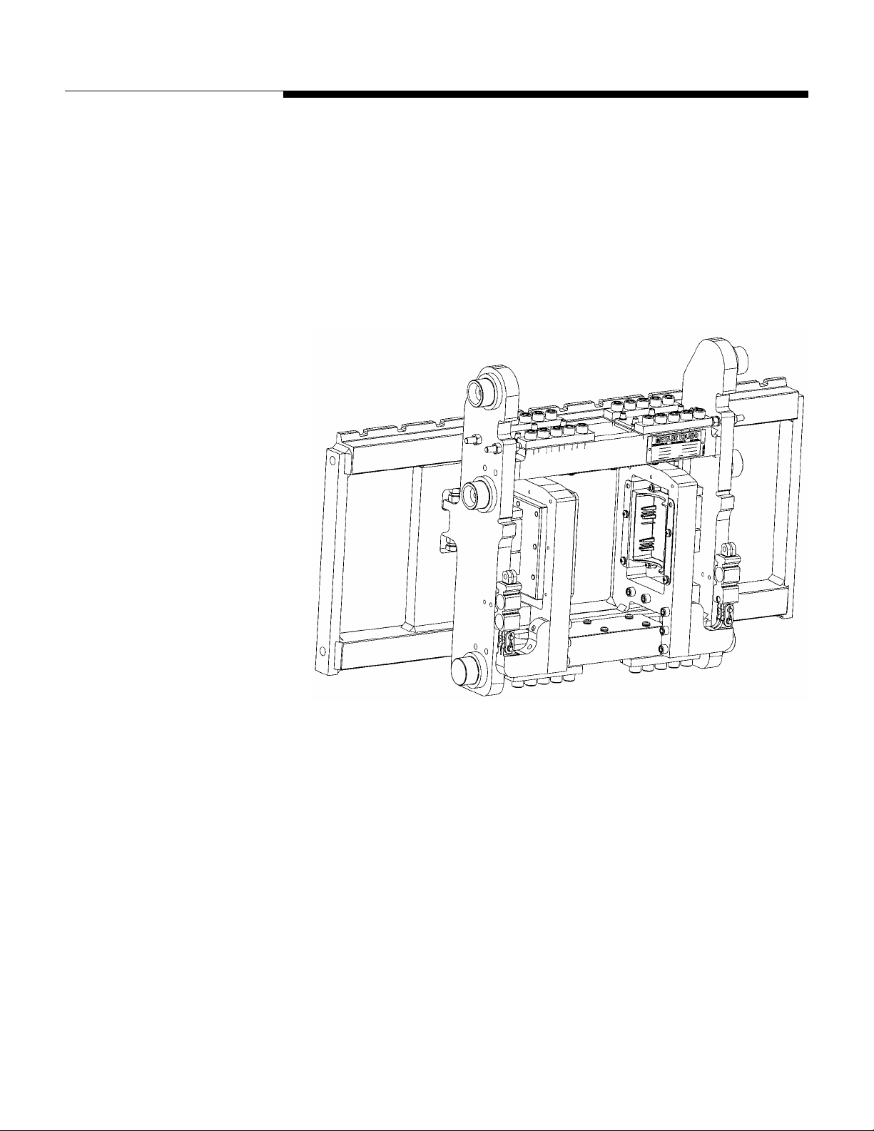
The MCFA forklift scale is a fully electronic scale with a capacity of 5,000 lb (2,000
kg). The scale consists of two components: (1) a scale carriage, which is installed in
place of the forklift truck’s lift bracket, and (2) a scale controller, which is mounted on
the forklift truck’s head guard. The scale carriage and controller communicate by radio,
so there are no wiring connections between them to limit the movement of the forks.
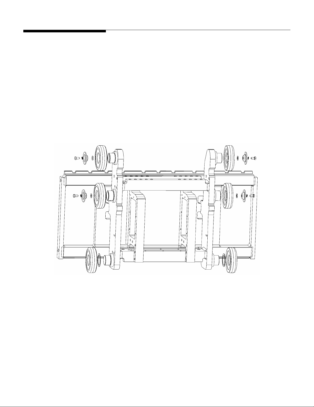
Figure 1-1: Forklift Scale Carriage (Simplex Version)
This manual explains how to install, operate, and service the MCFA forklift scale. If any
information in the manual is incorrect or missing, please use the Publication Suggestion
Report at the back of the manual to tell us about it.
(3/05)
1-1
METTLER TOLEDO MCFA Forklift Scale Service Manual
FCC Notice
MCPC Scale Controller (FCC ID: RITSC0001)
This device complies with Part 15 of the FCC Rules. Operation is subject to the following
two conditions: (1) this device may not cause harmful interference, and (2) this device
must accept any interference received, including interference that may cause undesired
operation.
MCSB Simplex Scale Carriage (FCC ID: RITTE0001)
This device complies with Part 15 of the FCC Rules. Operation is subject to the following
two conditions: (1) this device may not cause harmful interference, and (2) this device
must accept any interference received, including interference that may cause undesired
operation.
MCTB Triplex Scale Carriage (FCC ID: RITTE0002)
This device complies with Part 15 of the FCC Rules. Operation is subject to the following
two conditions: (1) this device may not cause harmful interference, and (2) this device
must accept any interference received, including interference that may cause undesired
operation.
CAUTION
CHANGES OR MODIFICATIONS NOT EXPRESSLY APPROVED BY METTLER TOLEDO COULD
VOID THE AUTHORITY TO OPERATE THIS EQUIPMENT.
1-2
(3/05)

Chapter 2: Installation
General
2
Installation
General
Tools
When you receive your forklift scale, check all items against the shipping bill of lading.
If any items are missing, notify the carrier immediately. Inspect the packing container
and scale for freight damage. If you find damage, contact your freight carrier
immediately in order to collect damages.
The following tools are needed to install and calibrate a forklift scale:
Simplex Version
Crane or lifting device (capacity 2,500 lb)
Torque wrench with 3/8-inch hex bit attachment (flexure bolts)
12-mm wrench (main roller bolts)
14-mm wrench (side roller assembly bolts)
24-mm wrench (chain anchor nuts)
3/4-inch wrench (bumper bolts and drag load cell mounting nuts)
10-mm wrench (bolts for mounting controller)
Triplex Version
Crane or lifting device (capacity 2,500 lb)
Torque wrench with 5/16-, 3/8-, and 1/2-inch hex bit attachments
12-mm wrench (main roller bolts)
16-mm wrench (side roller assembly bolts)
24-mm wrench (chain anchor nuts)
3/4-inch wrench (bumper bolts and drag load cell mounting nuts)
10-mm wrench (bolts for mounting controller)
1.25-inch open-end wrench
(3/05)
2-1
METTLER TOLEDO MCFA Forklift Scale Service Manual
Install Scale Controller
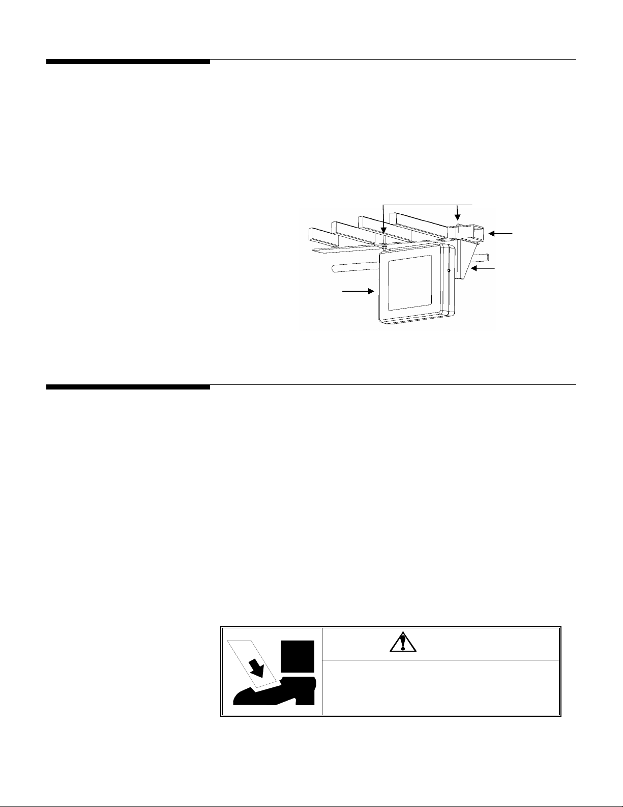
1.
Use a pair of U-bolts to attach the mounting bracket to the forklift truck’s head
guard. Position it so that the driver will be able to view the controller easily.
2.
Bolt the controller to the mounting bracket, using four hexagonal head screws and
washers (see Figure 2-1).
3.
Connect the controller to the forklift truck’s time-delay relay harness. The harness
should be installed according to the manufacturer’s instructions.
U-Bolts
Head Guard
Mounting Bracket
Scale Controller
Figure 2-1: Scale Controller and Mounting Bracket
Remove the Forklift
Truck’s Lift Bracket
1.
Park the forklift truck on a level surface, and make sure the mast is in the vertical
position.
2.
Remove both of the forks.
3.
If the forklift truck is equipped with a load backrest extension, remove the load
backrest extension.
4.
Raise the mast so that the lift bracket is at a comfortable working height (3 or 4 feet
off the ground).
5.
Wrap a sling securely around the lift bracket’s upper fork bar.
6.
Attach the sling to a crane (or other lifting device with a capacity of at least 500
lb), and use the crane to raise the lift bracket so that the chains have some slack in
them.
DANGER
BE SURE TO BLOCK THE LIFT BRACKET WHEN IT IS IN THE
RAISED POSITION. FAILURE TO OBSERVE APPROPRIATE
SAFETY PRECATIONS COULD RESULT IN BODILY HARM OR
PROPERTY DAMAGE.
2-2
(3/05)
Chapter 2: Installation
Remove the Forklift Truck’s Lift Bracket
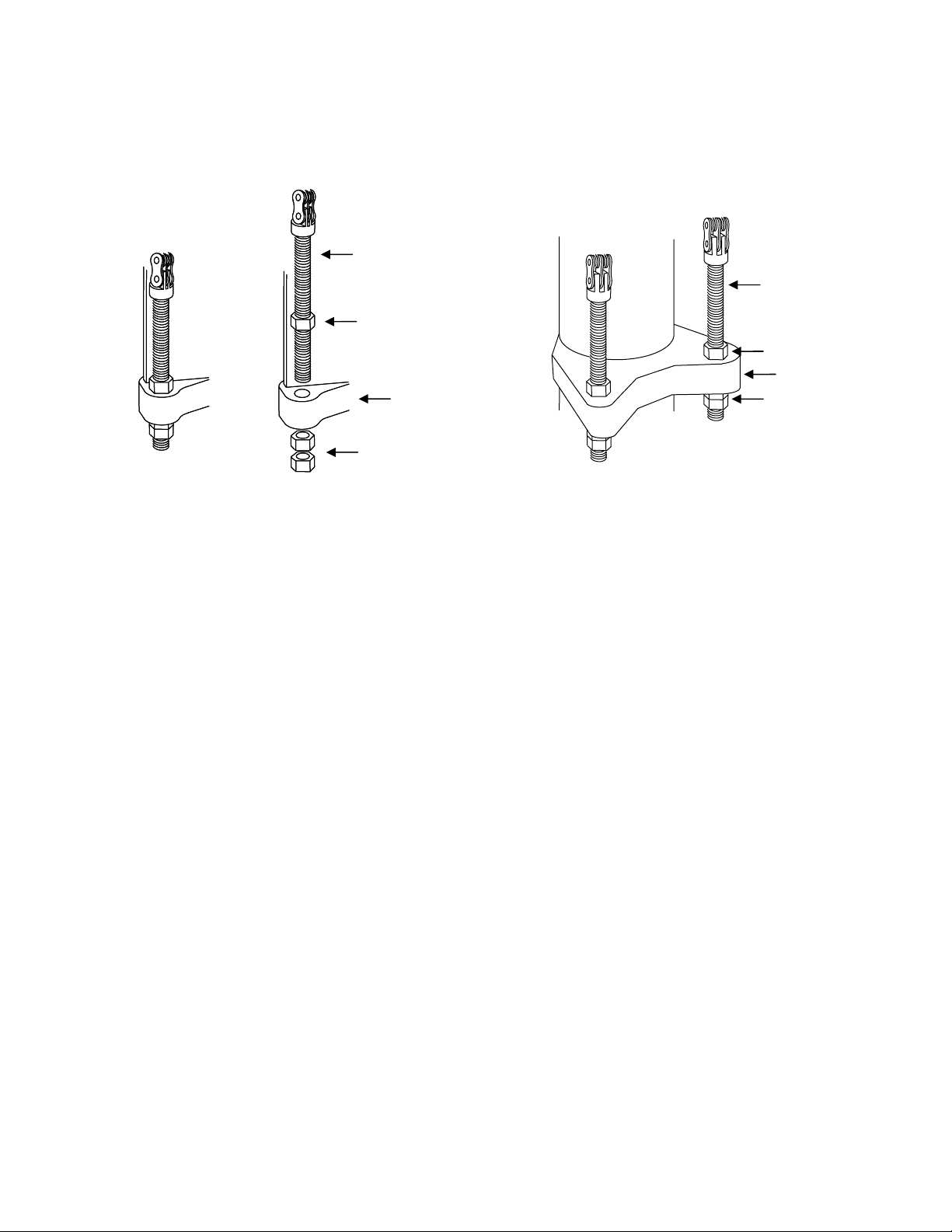
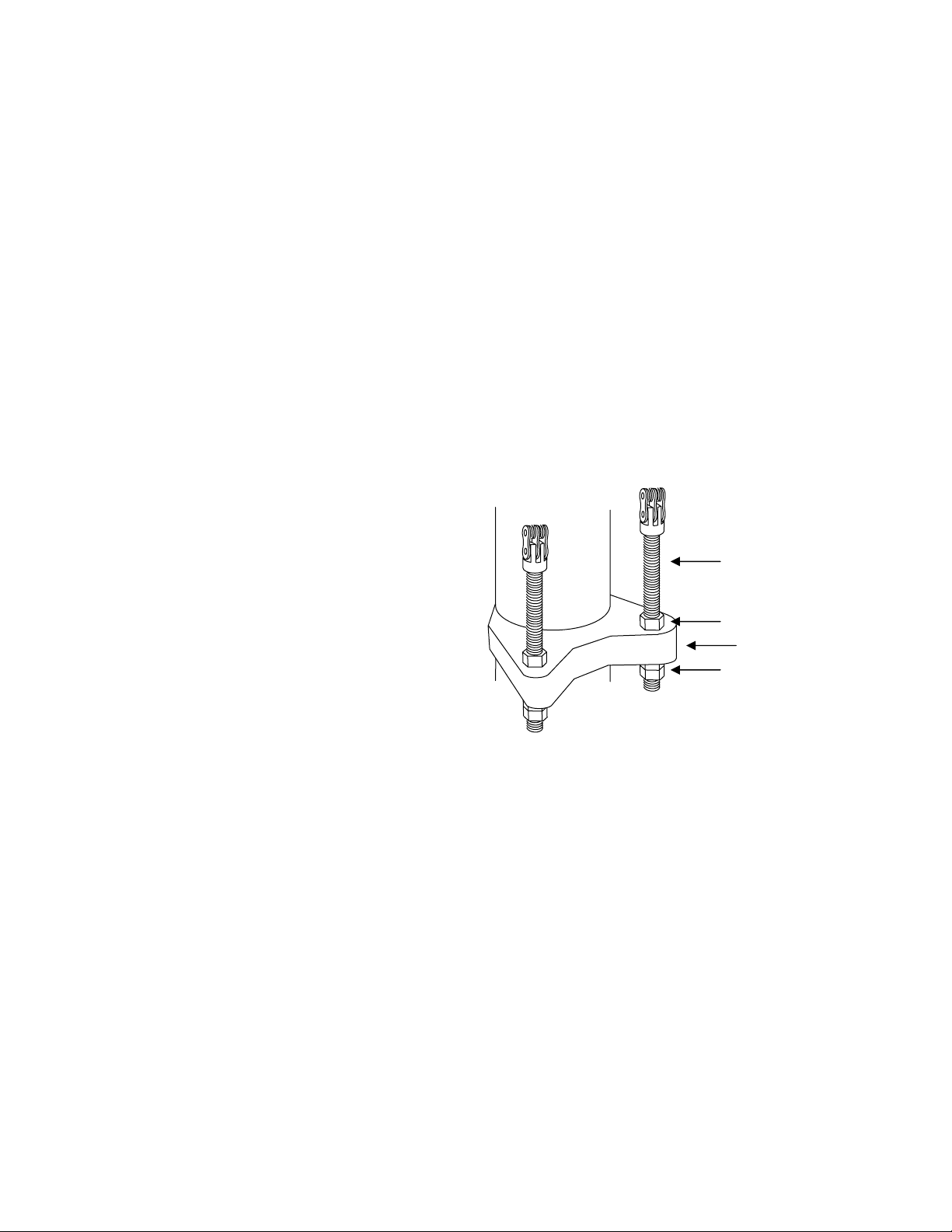
7.
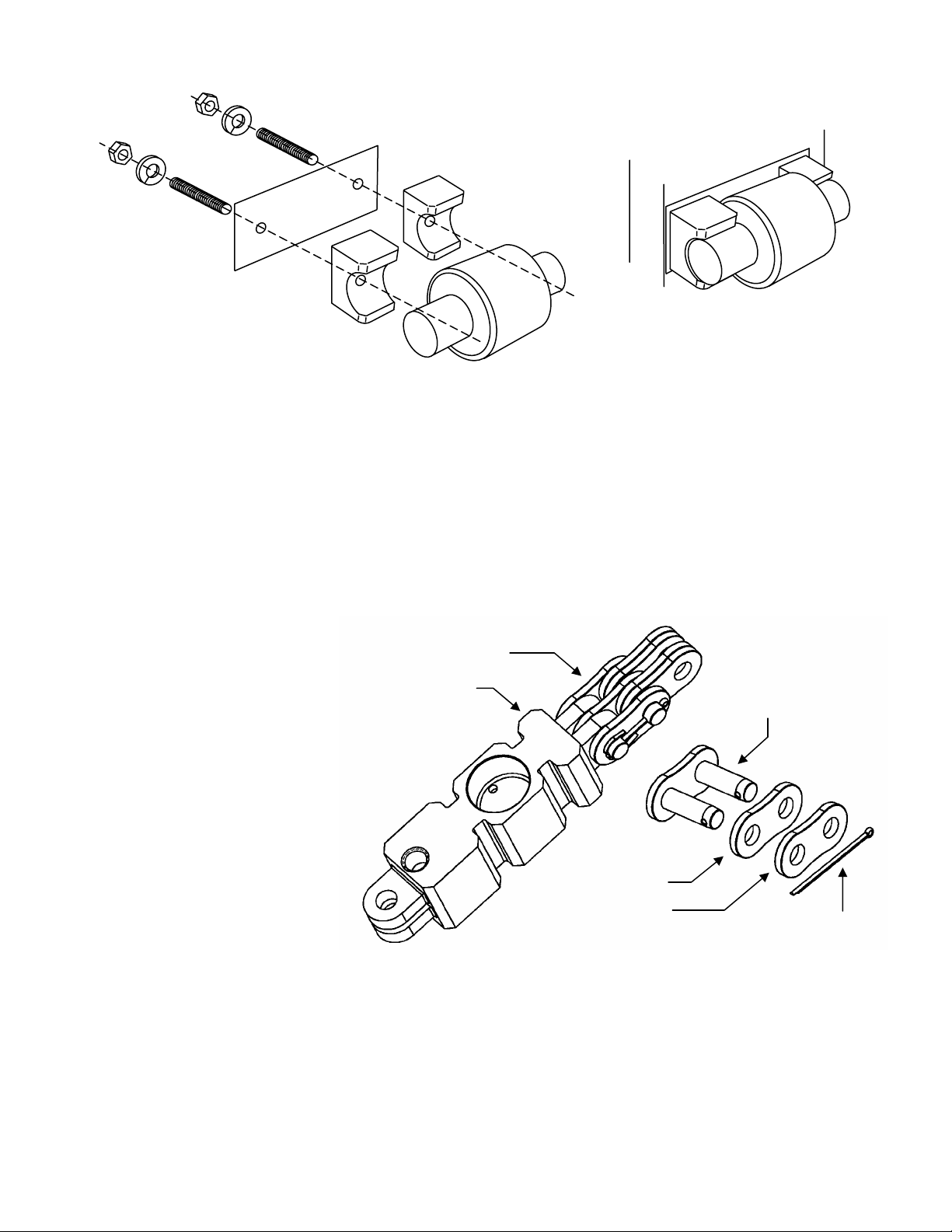
Disconnect the two chain anchors from the mast by removing the lower jam nut
from each anchor (see Figure 2-2). Keep the nuts with the chain anchor to use
them for installing the scale carriage.
Chain Anchor
Chain Anchor
Jam Nut
Jam Nut
Mast
Jam Nuts
Mast
Simplex Version
Jam Nuts
Triplex Version
Figure 2-2: Chain Anchor Assembly
8.
Remove the chains from the pulleys at the top of the mast. Then position the chains
over the front of the lift bracket so that they will not interfere with removing the lift
bracket from the mast.
9.
Raise the bottom of the inner mast at least 2 feet off the floor to allow enough room
to remove the lift bracket from the bottom of the mast.
10.
Use the crane to lower the lift bracket to the floor and remove it from the bottom of
the mast.
11.
Place the lift bracket on a stable working surface, with the front side of the lift
bracket facing downward to provide easy access to the rollers and chain mounts.
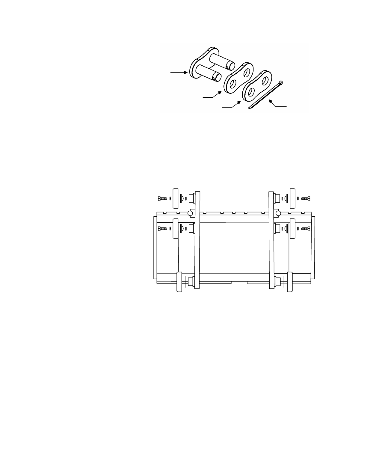
12.
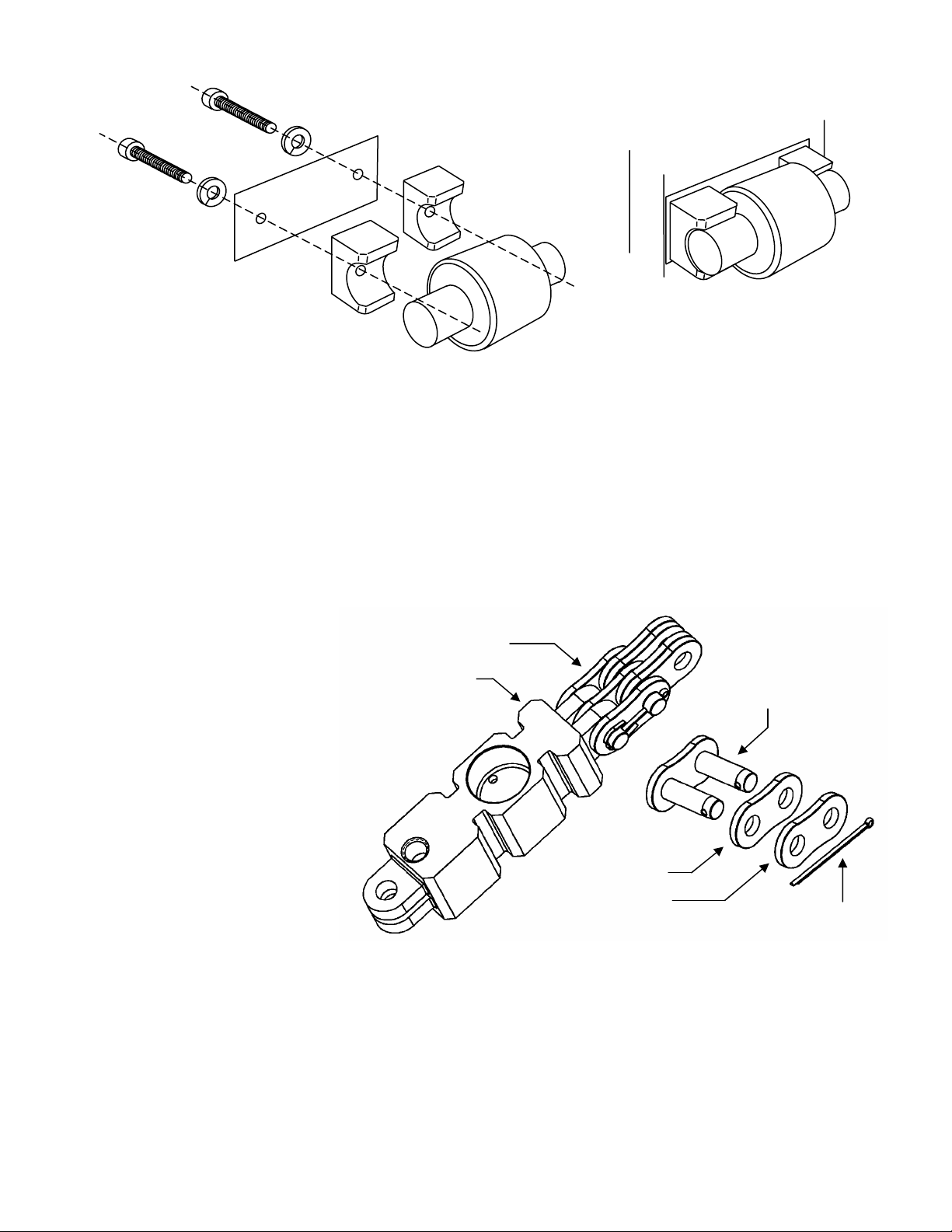
Disconnect the two chains from the lift bracket. Remove the cotter pin from the
master link that is connected to the 90° joint in each chain (see Figure 2-3). Then
take apart the master link, using a C-clamp or similar device to press the master
link through the link plates. Do not use a hammer or other tool to strike the master
link. It could damage the link. Keep the chains and master links to install on the
scale carriage.
(3/05)
2-3
METTLER TOLEDO MCFA Forklift Scale Service Manual
Master Link
Link Plate (Large Holes)
13.
Remove the six main rollers from the lift bracket (see Figure 2-4). The two top
rollers on each side of the lift bracket are secured with screws. The bottom roller on
each side of the lift bracket can be removed by hand. Save the rollers, screws,
washers, and shims so that you can install them on the scale carriage.
Link Plate (Small Holes)
Figure 2-3: Master Link Assembly
Cotter Pin
2-4
(3/05)
Figure 2-4: Remove Main Rollers
14.
Locate the side roller on each side of the lift bracket. Remove the two bolts that
secure each side roller assembly to the lift bracket (see Figure 2-5). Keep these
assemblies together because you will need to install them on the scale carriage.
Note the position of any shims used in the assemblies.
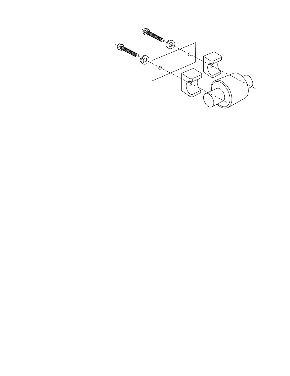
Figure 2-5: Side Roller Assembly
15.
Set the lift bracket aside, and remove the sling from it.
Chapter 2: Installation
Remove the Forklift Truck’s Lift Bracket
(3/05)
2-5
METTLER TOLEDO MCFA Forklift Scale Service Manual
Install the Simplex
Scale Carriage
1.
Park the forklift truck on a level surface, and make sure the mast is in the vertical
position.
2.
Place the scale carriage on a stable working surface, with the front side of the
carriage facing downward to provide easy access to the rollers and chain load
cells.
3.
Install the two lower main rollers by sliding them onto the roller shafts at the bottom
of each side of the scale carriage (see Figure 2-6). Be sure to install any shims that
were removed from the forklift truck’s lift bracket.
4.
Install the other four main rollers on the scale carriage, securing them with the bolts
that were removed from the lift bracket (see Figure 2-6).
2-6
(3/05)
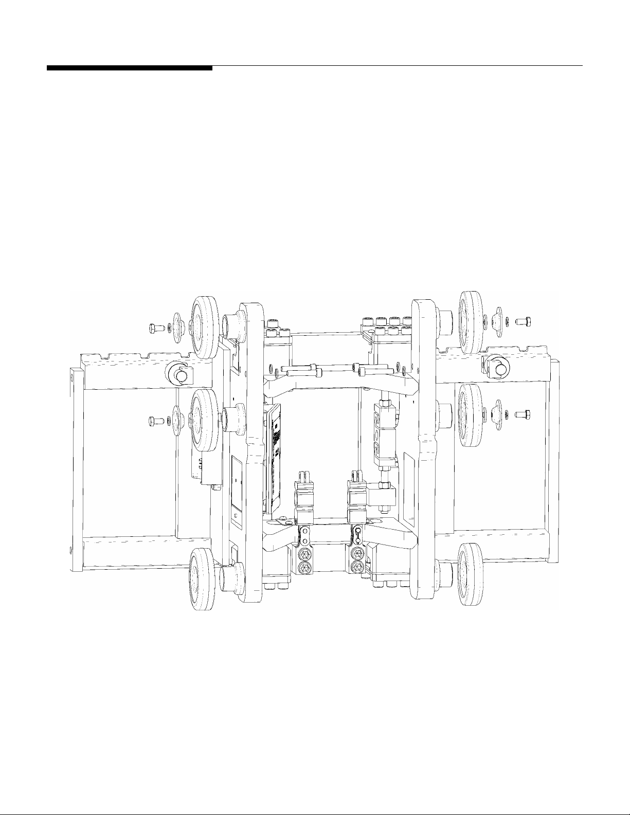
Figure 2-6: Install Main Rollers
5.
Mount the two side roller assemblies (including shims) on the scale carriage (see
Figure 2-7). Do not use the bolts that were removed from the lift bracket. Instead,
use the studs and nuts provided with the scale carriage. Align the two holes in each
side roller assembly with the holes located midway between the two bolted rollers
on each side of the carriage. Insert the studs in the holes and screw them into the
assembly. Then place the washers and nuts on the ends of the studs and tighten
them against the carriage.
Chapter 2: Installation
Install the Simplex Scale Carriage
Figure 2-7: Side Roller Assembly
6.
Use a master link to connect each chain to one of the chain load cells on the scale
carriage. Assemble the master link as shown in Figure 2-8. Using a C-clamp or
similar device, press the master link assembly together just enough so that you can
insert the cotter pin in the holes. If the link is too tight, it can bind against the load
cell and chain mount. If the link does not rotate freely on the load cell or chain,
press the master link back through the link plates until it rotates freely.
NOTE: When a forklift scale is installed, a standard chain should have 34 links
(including master links). Add or remove links if necessary.
Assembled Master Link
Chain Load Cell
Master Link
Link Plate
(Large Holes)
Link Plate
(Small Holes)
Figure 2-8: Connect Chain to Load Cell with Master Link
Cotter Pin
7.
Position the chains over the front of the carriage so that they will not interfere when
you install the carriage in the forklift mast.
8.
Raise the bottom of the inner mast at least 2 feet off the floor to allow enough room
to install the carriage from the bottom of the mast.
9.
Wrap a sling securely around the upper part of the scale carriage.
(3/05)
2-7
METTLER TOLEDO MCFA Forklift Scale Service Manual
10.
Attach the sling to a crane (or other lifting device with a capacity of at least 500
lb), and use the crane to lift the scale carriage. Position the carriage so that its
main rollers fit into the bottom of the mast channel. The chain load cells are loca
on the back side of the scale carriage.
11.
Raise the carriage to a comfortable working position, keeping the main rollers
aligned inside the mast channel. Move the carriage up and down several times
make sure that it moves freely within the mast. If the carriage fits too tightly within
the mast, you might need to remove shims from the bottom rollers or side rollers.
ted
to
12.
Position two blocks of wood (3 inches high) on the floor under the carriage’s lowe
fork bar. Lower the inner mast and carriage until the fork bar rests on the blocks.
13.
Route the chains over the pulleys at the top of the mast.
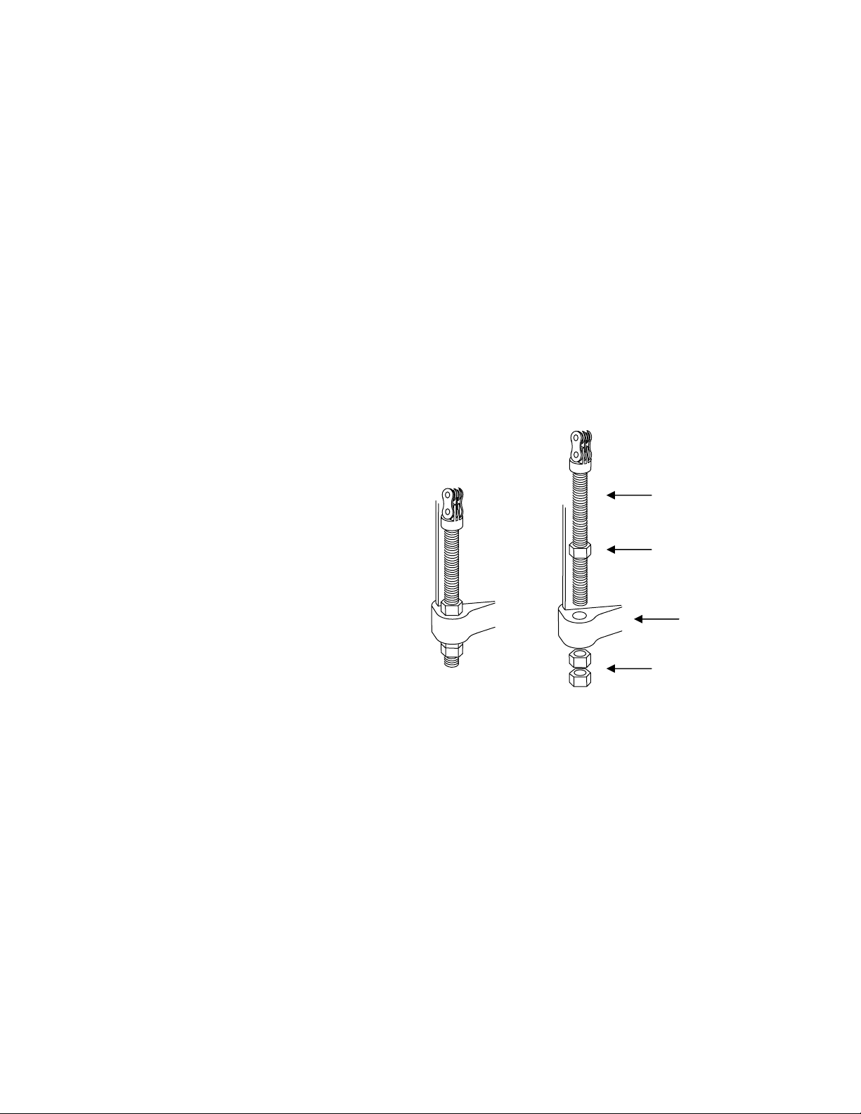
14.
Remove the lower nut from each chain anchor and insert
the anchor into the hole in
the mast, below and behind the chain pulleys. Place the lower nut on the threaded
anchor and tighten it until both it and the upper nut are tight against the mast (see
Figure 2-9). You will need to adjust the anchors later, so do not tighten the nuts too
much. Make sure there is no slack in the chains, so that the carriage does not drop
when you remove the sling.
Chain Anchor
Jam Nut
Mast
r
2-8
(3/05)
Jam Nuts
Figure 2-9: Chain Anchor Assembly
5.
Remove the sling from the scale carriage.
1
16.
Raise the carriage slightly. Put the forks ba
ck on the lift truck, positioning a fork at
the next to last notch on each side of the carriage.
17.
Lower the carriage to the floor so that the stages of
the mast are completely
collapsed.
18.
Adjust the c
hain anchors so that each chain has 3/4 inch of slack. This will allow
room for the chains to adjust when the mast is set at an angle. With the mast in the
vertical position and the carriage fully lowered, the distance between the floor and
the bottom of the scale carriage should be 76 to 80 mm (about 3 inches).
19.
After installing the scale controller and scale carriage, place a pallet on the fo
and exercise the scale to make sure that all components seat properly. Repeatedly
place a test weight on the scale, positioning it on the center of the scale and at
each corner of the scale.
rks
Install the Triplex Scale
Carriage
Chapter 2: Installation
Install the Triplex Scale Carriage
1.
Park the forklift truck on a level surface, and make sure the mast is in the vertical
position.
2.
Place the scale carriage on a stable working surface, with the front side of the
carriage facing downward to provide easy access to the rollers and chain load
cells.
3.
Install the
two lower main rollers by sliding them onto the roller shafts at the bottom
of each side of the scale carriage (see Figure 2-10). Be sure to install any shim
that were removed from the forklift truck’s lift bracket.
4.
the other four main rollers on the scale carriage, securing them with the bolts
Install
that were removed from the lift bracket (see Figure 2-10).
s
Figure 2-10: Install Main Rollers
5.
Mount the two side roller assemblies (including shims) on the scale carriage (see
Figures 2-10 and 2-11). Align the two holes in each side roller assembly with the
h o bolted rollers on each side of the carriage.
oles located midway between the tw
Use two socket head screws and washers to secure each side roller assembly.
(3/05)
2-9
METTLER TOLEDO MCFA Forklift Scale Service Manual
Figure 2-11: Side Roller Assembly
6.
Use a master link to connect each chain to one of the chain load cells on the scale
carriage. Assemble the master link as
similar device, press the master link assembly together just enough so that you can
insert the cotter pin in the holes. If the link is too tight, it can bind against the load
cell and chain mount. If the link does not rotate freely on the load cell or chain,
press the master link back through the link plates until it rotates freely.
shown in Figure 2-12. Using a C-clamp or
NOTE: When a forklift scale is installed, a standard chain should have 33 links
(including master links). Add or remove links if necessary.
As
sembled Master Link
Chain Load Cell
Master Link
Link Plate
(Large Holes)
Link Plate
(Small Hol
Figure 2-12: Connect C d C nk
hain to Loa ell with Master Li
es)
Cotter Pin
2-10
(3/05)
7.
Position the chains over the front of the carriage so that they will not interfere when
you insta
.
Raise the bottom of the inner mast at least 2 feet off the floor to allow enough room
8
ll the carriage in the forklift mast.
to install the carriage from the bottom of the mast.
9.
Wrap a sling securely around the upper par
t of the scale carriage.
Chapter 2: Installation
Install the Triplex Scale Carriage
10.
Attach the sling to a crane (or other lifting device with a capacity of at least 500
lb), and use the crane to lift the scale carriage. Pos
main rollers fit into the bottom of the mast channel. The chain load
ition the carriage so that its
cells are located
on the back side of the scale carriage.
11.
Raise the carriage to a comfortable working position, keeping the main rollers
aligned inside the mast channel. Move the carriage up and down several times to
make sure that it moves freely within the mast. If the carriage fits too tightly within
the mast, you might need to remove sh
ims from the bottom rollers or side rollers.
12.
Position two blocks of wood (3 inches high) on the floor under the carriage’s lower
fork bar. Lower the inner mast and carriage until the fork bar rests on the blocks.
13.
Route the chains over the pulleys at the top of the mast.
14.
Remove the lower nut from each chain anchor and insert the anchor into the hole in
the mast, below and behind the chain pulleys. Place the lower nut on the threaded
anchor and tighten it until both it and the upper nut are tig
Figure 2-13). You will need to adjust the anchors later, s
ht against the mast (see
o do not tighten the nuts
too much. Make sure there is no slack in the chains, so that the carriage does not
drop when you remove the sling.
Chain Anchor
Jam Nut
Mast
Jam Nuts
Figure 2-13: Chain Anchor Assembl
y
15.
Remove the sling from the scale carriage.
16.
Raise the carriage s , positioning a fork at
lightly. Put the forks back on the lift truck
the next to last notch on each side of the carriage.
17.
Lower the carriage to the floor so that the s
tages of the mast are completely
collapsed.
18.
Adjust the chain anchors so that each chain has 3/
4 inch of slack. This will allow
room for the chains to adjust when the mast is set at an angle. With the mast in the
vertical position and the carriage fully lowered, the distance between the floo
the bottom o
19.
After installing the scale controller and scale carriage, place a pallet on the forks
f the scale carriage should be 76 to 80 mm (about 3 inches).
and exercise the scale to make sure that all components seat properly. Repeatedly
place a test weight on the scale, positioning it on the center of the scale and at
each corner of the scale.
(3/05)
r and
2-11
METTLER TOLEDO MCFA Forklift Scale Service Manual
Batteries
A 12-volt battery pack is used to power the scale’s load cells and carriage radio. The
scale is supplied with two batteries and a battery charger. New batteries must be
charged before they can be used. A fully charged battery will allow you to operate the
scale for up to 36 hours. The battery level indicator on the scale controller’s main
weighing screen alerts the driver when the battery’s voltage level is low.
CAUTION
THERE IS A RISK OF EXPLOSION IF A BATTERY IS REPLACED WITH AN INCORRECT
TYPE OF BATTERY. DISPOSE OF BATTERIES ACCORDING TO LOCAL REGULATIONS.
FOR DISPOSAL INFORMATION, REF NFORMATION SHEET FOR
NICKEL METAL HYDRIDE BATTERIE sonic.com OR REFER TO
THE RECHARGEABLE BATTERY RECYCLING CORPORATION (www.rbrc.org).
ER TO THE PRODUCT I
S (NiMH) AT www.pana
• tion the
To install a battery, insert it in the scale carriage’s battery compartment. Posi
battery so that the metal contacts on its side fit against the metal contacts in
the
battery compartment.
To remove a battery, press the plastic tab toward the center of the battery and pull
•
the battery out of the battery compartment.
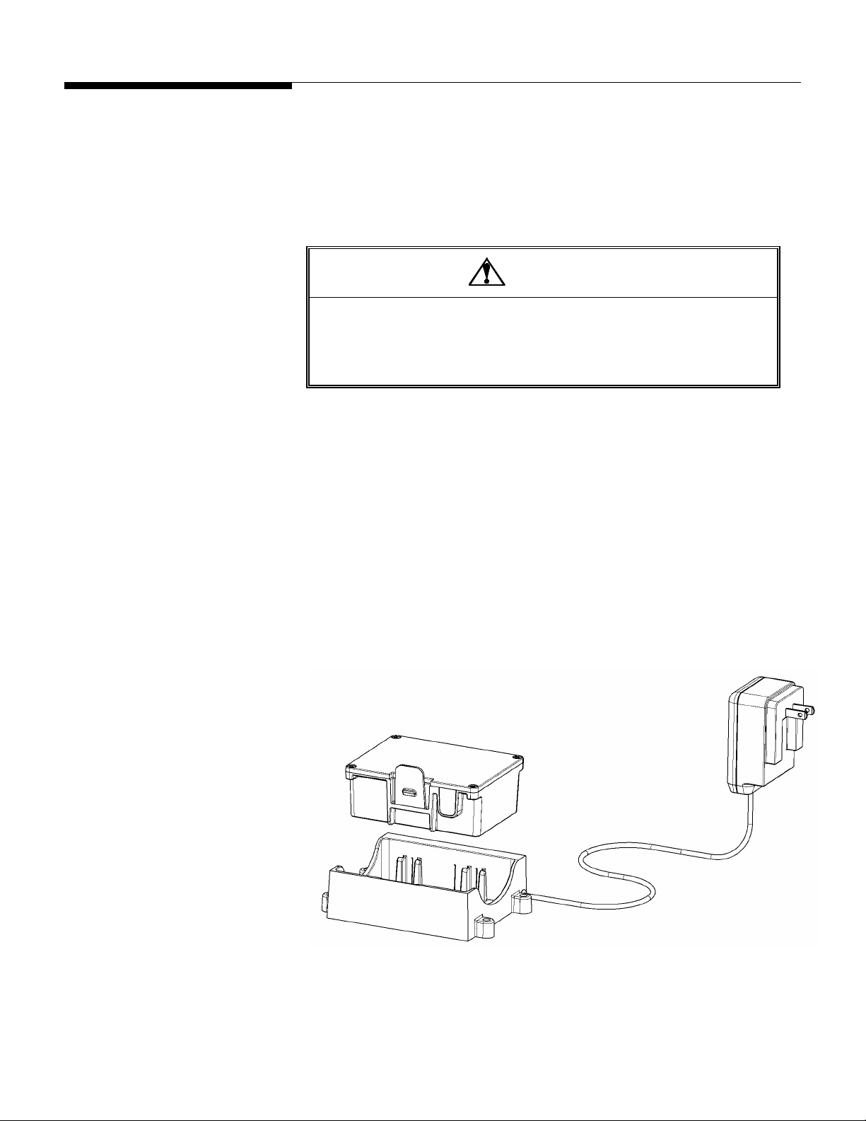
•
To charge a battery, insert it in the battery charger (see Figure 2-14). Then plug the
battery charger into a standard electrical
outlet (110 volts). It will take 12 to 16
hours to provide the initial charge for a new battery. Once a battery has been used,
it should take no more than 3 to 4 hours to
recharge it. A red light on the battery
charger indicates that the battery is being charged. A green light indicates that the
battery is fully charged. When a battery is fully charged, the charger goes into
trickle mode, so there is no danger of damaging a battery by overcharging it.
2-12
Figure 2-14: Battery and Batter Charger
(3/05)

Geo Index
Chapter 2: Installation
Geo Index
To compensate for local gravitational forces, change the geo index to the setting for the
location where the scale will be used. The factory default setting is 16 (the geo index for
Worthington, Ohio, USA). To determine the geo index for a location, refer to the
appendix (Chapter 10). You must know the geographical coordinate for the location
and the elevation above sea level.
1.
To change the geo index, enter the scale controller’s setup mode by touching the
Setup button on the main weighing screen.
2.
Touch the Scale button, touch the Calibration button, and then touch the Where
Used button.
3.
A keypad is used to enter the geo index. Type a number in the data field by
touching the numeric keys on the keypad (the range is 0 to 31). Touch the Clear
button if you wish to clear the data field and start over.
4.
Touch the Enter button to confirm your selection or the Cancel button to cancel any
changes that you made.
Shift Adjustment
Forklift scales are calibrated at the factory and should not need to be recalibrated when
they are installed. You should, however, check the scale after installing it to see if it
needs to be shift adjusted. A correctly adjusted scale will give you the same weight
reading no matter where on the forks you place a test weight. If the weight readings at
the shift test locations are out of tolerance, shift adjust the scale to correct the problem.
Park the forklift truck on a level surface, place a pallet on the forks, raise the forks 12 to
15 inches off the ground, set the mast to the vertical position, and shut off the forklift
truck’s motor. Then check the scale’s repeatability by placing a test weight on the same
location on the pallet several times to make sure that you get the same weight reading
each time.
After verifying the scale’s repeatability, check to see if the scale needs to be shift
adjusted. For shift adjustments, we recommend using test weights equal to one half the
scale’s maximum weighing capacity. The test weights must meet the specified National
Institute of Standards and Technology Handbook 44 accuracy requirements.
NOTE: When performing a shift adjustment, use the weight readings on the data screen
instead of those on the main weighing screen. The weight readings on the data screen
are displayed to two decimal places, although the number in the second decimal place
might not be stable.
(3/05)
2-13
METTLER TOLEDO MCFA Forklift Scale Service Manual
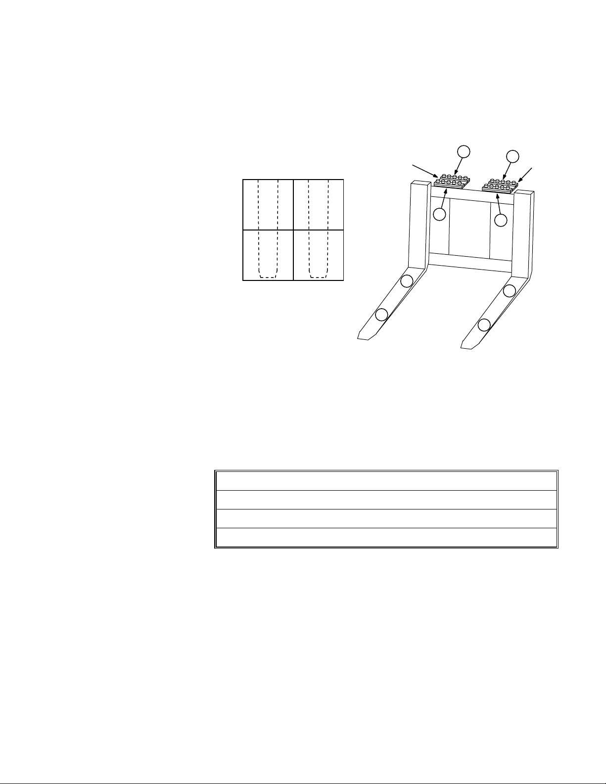
Shift Test Locations
Place a pallet or other flat surface (approximately 4 feet by 4 feet) on the forks and
make sure that it is level. Figure 2-15 shows test weight locations (1, 2, 3, and 4) at
the center of each quadrant of the pallet. Place the test weight at location 1 and record
the weight reading. Then move the test weight to location 2 and record the weight
reading. Continue until you have taken a weight reading at each of the four locat
ions.
Heel Heel
Flexure
B
C
Flexure
1
4
A
D
2 3
Toe Toe
1
4
2
3
Figure 2-15: Shift Adjustment Locations (Simplex Version Shown)
Ideally, the scale will give you the same weight reading at all four locations. The weight
readings at the heel and toe of either or both forks should be within Handbook 44
tolerance requirements (±2.5 lb for weights up to 2,500 lb). If the weight readings are
out of tolerance, you will need to shift adjust the scale. This is done by adding shims to
the flexures at the locations shown in Figure 2-15. To determine where to add shims,
refer to Table 2-1.
2-14
(3/05)
If weigh
t reading 1 is greater than 2
If weight reading 2 is greater than 1
If weight reading 3 is greater than 4
If weight reading 4 is greater than 3
→
→
→
→
Shim at location A
Shim at location B
Shim at location C
Shim at location D
Table 2-1: Shim Locations
The shims adjust the differences between the weight readings at the heel and toe of an
dividual fork. Adjust the weight readings so that they are as near to equal as possible.
in
If one weight reading is slightly higher, it should be the reading at the toe of the fork.
Shimming at the front of a flexure (location A) will increase the weight reading at the toe
of the fork (location 2). Because the shim affects the entire fork, it will also slightly
increase the weight reading at the heel (location 1).
Shimming at the back of a flexure (location B) will decrease the weight reading at the
toe of the fork (location 2). Because the shim affects the entire fork, it will also slightly
decrease the weight reading at the heel (location 1).
A pallet places load on both forks. So when a pallet is used, shimming under a flexure
will affect the readings at all four test weight locations. For example, shimming at
Chapter 2: Installation
Shift Adjustment
location A or B will ch
ange the readings at locations 1 and 2, but it will also change the
readings at locations 3 and 4 to a lesser extent.
Keep in mind that, in addition to balancing the weight readings at the heel and toe of
each fork, you are also trying to balance the weight readings of the two forks.
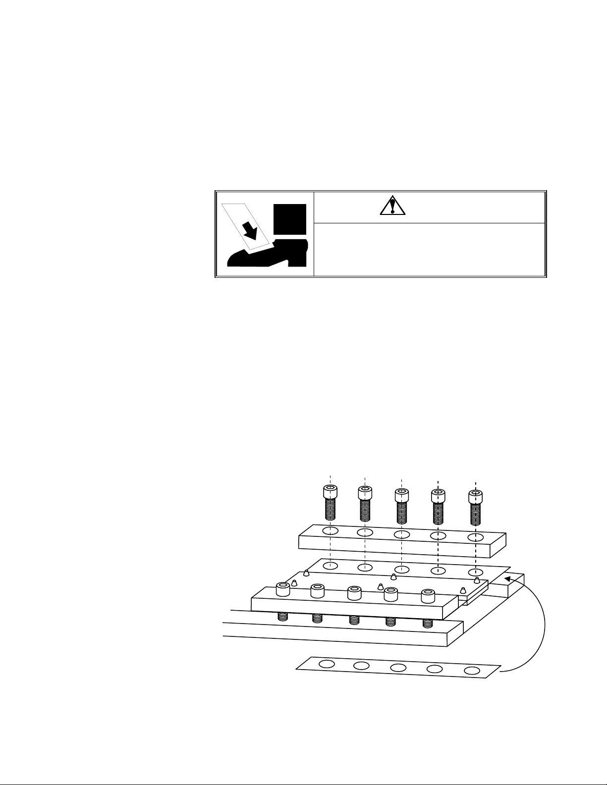
Shimming Procedure
o not remove the bolts from more than one flexure at a time. The flexures connect the
D
o se
tw ctions of the scale carriage. If you unbolt the two top or bottom flexures, the
ections of t rriage c separate an injury or damage the flex .
s he ca ould d cause ures
DANGER
DO NOT REMOVE THE BOLTS FROM MORE THAN ONE
FLEXURE AT A TIME WHILE THE CARRIAGE IS INSTALLED
N THE FORKLIFT. UNBOLTING MORE THAN ONE FLEXURE
O
OULD RESULT IN BODILY HARM OR PROPERTY DAMAGE.
C
1.
Remove the bolts from the side of the flexure where shims will be added.
.
Loosen the bolts on the opposite side of the flexure.
2
.
Place a shim under the flexure, aligning the bolt holes in the sh with those in the
3
im
flexure. We recommend starting with the thinnest shim and gradually increasing
the shim thickness as needed to balance the weight readings.
4.
Repl ).
ace the bolts that were removed, and tighten all bolts (torque to 90 ft-lb
5.
Repeat steps 1-4 for the second flexure if needed.
6.
Take new weight readings at all four test weight locations. If the weight readings
are still not equal, repeat the procedure to add additional shimming.
7.
When you have finished shift adjusting the scale, you should get approximately th
same weight re
ading at all four test weight locations.
Remove bolts
to add shim
e
Lo
osen bolts
on opposite
side of flexure
Figure 2-16: Shimming Procedure (Sim
plex Version Shown)
(3/05)
shim
Add
under flexure
2-15
Chapter 3: Scale Operations
Power-up Sequence
3
Scale Operations
Power-up Sequence
Weighing Screen
Radio Channel
Radio Communication
Remove all load from the forks and raise the forks off the ground whenever you power
up the scale controller. Start the forklift truck’s motor, and then press the on/off button in
the upper right-hand corner of the controller’s front cover. During the controller’s powerup sequence, it will display the version number and build number of the scale software.
When the controller is fully powered up, it will display the main weighing screen.
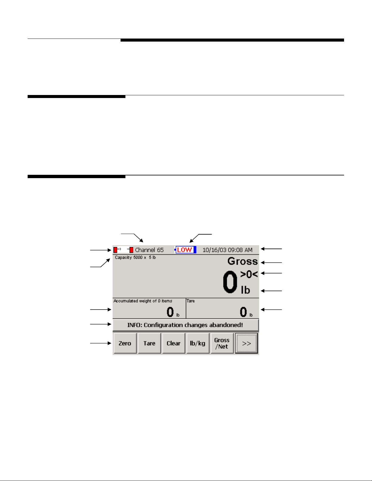
All weighing operations can be performed from the scale controller’s main weighing
screen. In addition to displaying current weight data, the screen provides push buttons
used to perform weighing operations and to enter setup mode.
Battery Level Indicator
Time and Date
Maximum Capacity
and Increment Size
Accumulated Weight
Message Bar
Push Buttons
Weighing Mode
“~” Indicates when
Scale is in Motion
Weight Reading
Tare Weight
Figure 3-1: Main Weighing Screen
Radio Communication: When the indicator is green, the radios are communicating.
When it is red, there is no communication.
Battery Level Indicator: The blue color indicates the battery level. The indicator will
display a warning message when the battery level is low and when the battery needs to
be changed. The battery discharge cradle has a low-voltage cutoff that shuts off power
to the scale carriage when the battery voltage drops to the “change battery” level
(approximately 10.5 volts).
(3/05)
3-1
METTLER TOLEDO MCFA Forklift Scale Service Manual
Push Buttons
The push buttons at the bottom of the main weighing screen are used to perform
weighing functions and to enter setup mode.
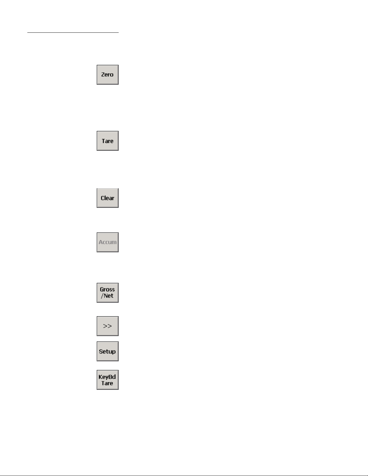
Zero
The Zero button is used to zero the scale manually. This feature can be used if the
weight reading on the screen does not return to zero when all load has been removed
from the scale. In order for this button to zero the scale manually, (1) the scale must be
in gross weighing mode and (2) the weight reading on the screen must be within the
range specified in the manual range setup feature. The scale also includes an automatic
zero maintenance (AZM) feature. When AZM is enabled, the scale will be zeroed
automatically if the weight reading is within a specified range.
Tare
The Tare button is used to assign the weight that is currently on the scale as a tare
weight. The tare weight is the weight of an empty pallet or container. It is subtracted
from the gross weight (weight of the loaded pallet or container) to determine the net
weight (weight of the item on the pallet or the material in the container). The tare weight
will be displayed in the Tare field. This button will work only if push button tare is
enabled in scale setup.
Clear
The Clear button is used to remove a tare weight reading or accumulated weight
reading that is displayed on the screen. To remove a tare weight reading, touch the
Clear button and then touch the Tare button. To remove an accumulated weight
reading, touch the Clear button and then touch the Accum button.
Accumulator
The Accum button is used to accumulate a series of weights and sum them to calculate
a total weight. When you touch the Accum button, the gross or net weight that is
displayed on the screen will be added to the weight reading in the Accumulated Weight
field. This button will be available only if basic accumulate is enabled in application
setup.
Gross/Net
The Gross/Net button is used to switch between gross and net weight readings on the
screen. In order to switch to a net weight reading, you must first assign a tare weight.
This button will work only if gross/net switching is enabled in scale setup.
>>
The double arrow button is used to display additional push buttons on the screen.
Setup
The Setup button is used to enter setup mode on the controller. For an explanation of
the setup features and how to use them, refer to the “Scale Setup” section of this
manual.
3-2
(3/05)
Keyboard Tare
The Keybd Tare button is used to enter a tare weight manually. The tare weight is the
weight of an empty pallet or container. It is subtracted from the gross weight (weight of
the loaded pallet or container) to determine the net weight (weight of the item on the
pallet or the material in the container). When you touch the Keybd Tare button, a
keypad will appear on the screen. Type the tare weight by touching the numerical keys
on the keypad. Then touch the
Enter button. The tare weight will be displayed in the Tare
field. This button will work only if keyboard tare is enabled in scale setup.
Chapter 3: Scale Operations
Weighing Operations
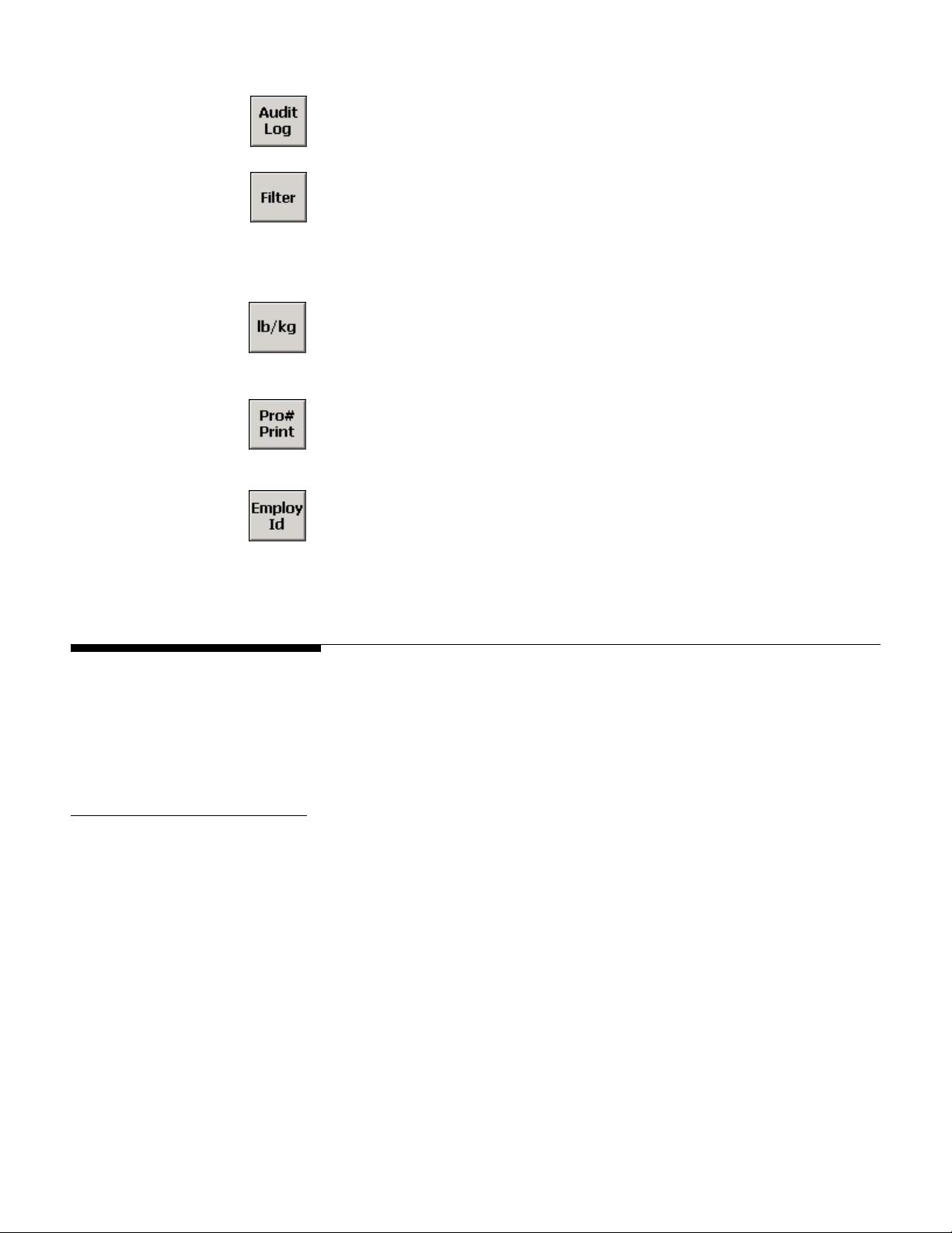
Audit Log
The Audit Log button is used to view the scale’s log that is required for Weights and
Measures audits. The log lists all calibration and configuration changes.
Filter
The Filter button is used to adjust the vibration filtering for the scale. It lets you adjust
filtering without entering setup mode. You can disable filtering or specify a filtering level
(Light, Lt/Med, Medium, Med/Hvy, or Heavy). Any changes made using this button will
be lost when the scale controller is shut off. At power-up, the scale will revert to the filter
settings that are specified in setup mode.
lb/kg
The lb/kg button is used to switch between weight readings in pounds and kilograms. It
changes the unit of measure for all weights displayed on the screen. This button will
work only if unit switching is enabled in scale setup.
Pro Number
The Pro# Print button is used to enter a shipping number for a SmartWeigh transaction
and create a record of the transaction. This button will be available only if advanced
accumulate is enabled in application setup.
Employee ID
Weighing Operations
Gross Weighing
The Employ ID button is used to enter an Employee ID for a SmartWeigh transaction.
This button will be available only if advanced accumulate is enabled in application
setup. When you touch the button, a keypad will appear on screen. Type the Employee
ID by touching the keys on the keypad. Then touch the Enter button.
This section describes the scale’s basic weighing operations, which are performed from
the controller’s main weighing screen. You can display a gross weight, use a tare
weight to determine a net weight, and use the accumulator to calculate the sum of a
series of gross or net weights.
Use the following procedure to find the gross weight of an item:
1.
Lift the item with the forklift.
2.
The gross weight will be displayed in the Weight field.
(3/05)
3-3

METTLER TOLEDO MCFA Forklift Scale Service Manual
Net Weighing with Push
Button Tare
Push button tare must be enabled in scale setup. Use the following procedure to find the
net weight of an item:
1.
Lift the empty pallet (or container) with the forklift.
2.
The weight will be displayed as a gross weight in the Weight field.
3.
Touch the Tare button.
4.
The weight of the pallet (or container) will be displayed in the Tare field. The
reading in the Weight field will change to zero.
5.
Lift the loaded pallet (or container) with the forklift. You can remove the pallet (or
container) from the forklift to fill it or fill it while it is on the scale.
6.
The net weight of the item will be displayed in the Weight field. If you wish to view
the gross weight of the loaded pallet (or container), touch the Gross/Net button.
7.
If auto clear is enabled, the gross/net weight and tare weight readings on the screen
will automatically return to zero when the load is removed from the scale.
Otherwise, the tare weight will remain on the screen and can be used to weigh
another loaded pallet (or container). To clear the tare weight, touch the Clear button
and then the Tare button.
Net Weighing with
Keyboard Tare
Keyboard tare must be enabled in scale setup. Use the following procedure to find the
net weight of an item:
1.
Lift the loaded pallet (or container) with the forklift.
2.
The weight will be displayed as a gross weight in the Weight field.
3.
Touch the Keybd Tare button.
4.
A keyboard will appear on the screen. Type in the tare weight of the pallet (or
container) by touching the numerical keys on the keyboard. When the correct tare
weight is displayed in the keyboard’s data field, touch the Enter button.
5.
The net weight of the item will be displayed in the Weight field. If you wish to view
the gross weight of the loaded pallet (or container), touch the Gross/Net button.
The tare weight will be displayed in the Tare field.
6.
If auto clear is enabled, the gross/net weight and tare weight readings on the screen
will automatically return to zero when the load is removed from the scale.
Otherwise, the tare weight will remain on the screen and can be used to weigh
another loaded pallet (or container). To clear the tare weight, touch the Clear button
and then the Tare button.
NOTE: You can also use keyboard tare to enter a tare weight before lifting the loaded
pallet (or container) with the forklift.
3-4
(3/05)
 Loading...