

Mettler Toledo AX, MX, UMX, AX106 Comparator, AX206 Comparator Operating Instructions Manual
...Page 1
Operating Instructions
METTLER TOLEDO
AX and MX/UMX Balances
Page 2
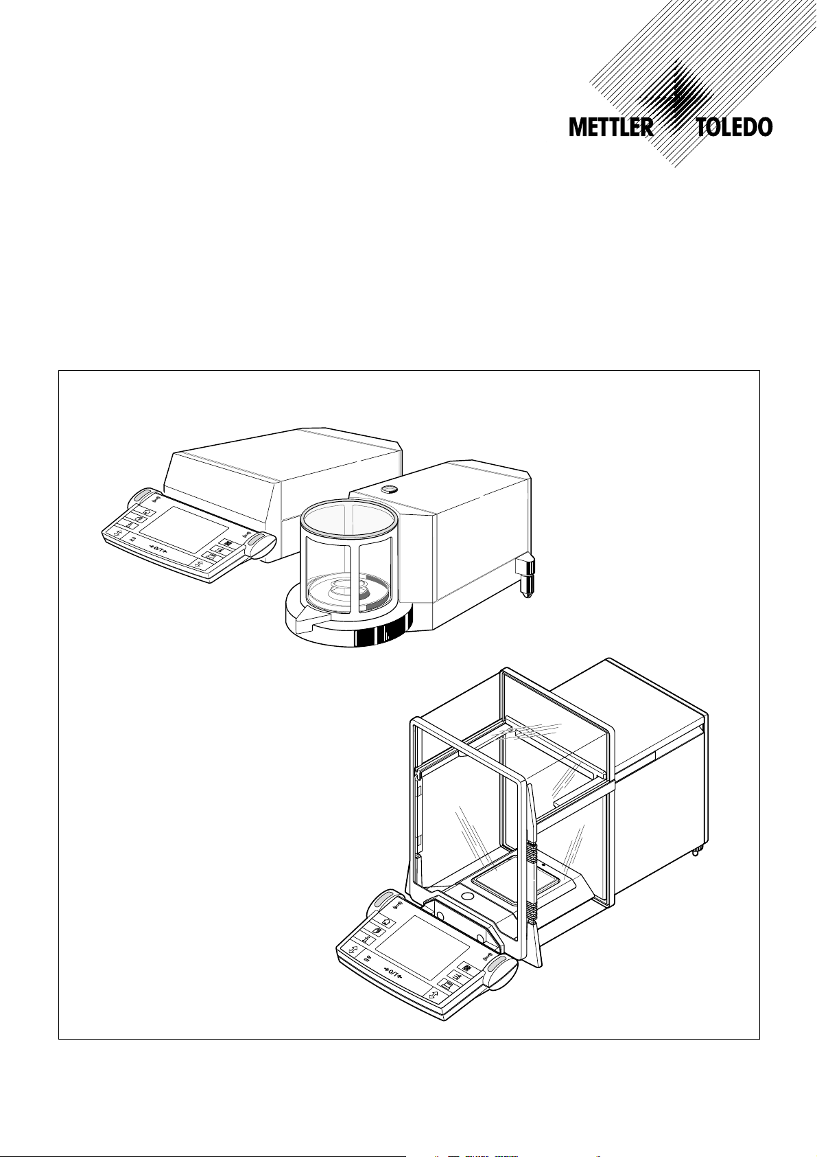
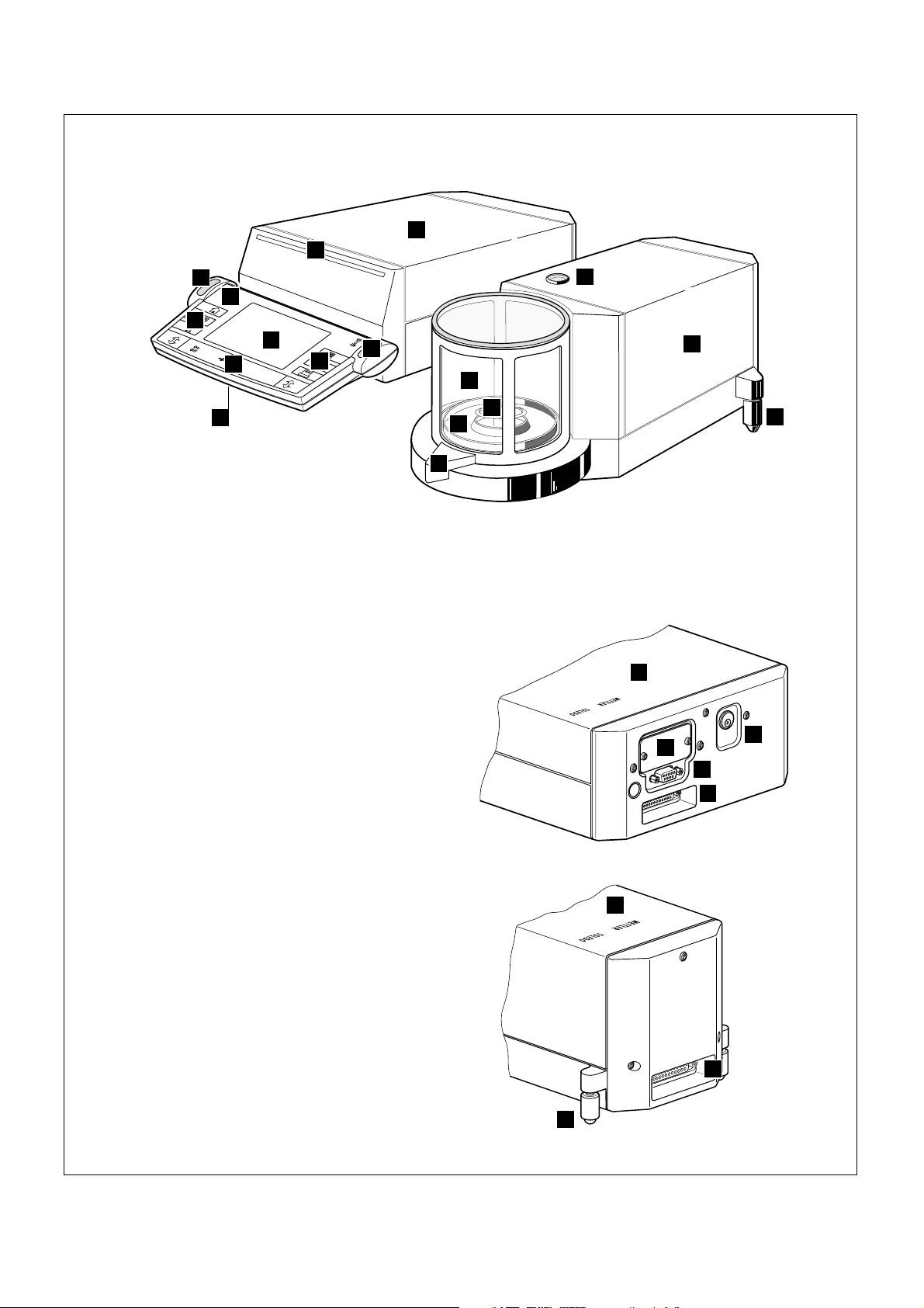
Overview of your AX balance
10
11
4
3
2
3
5
1 Terminal (for details s. Chapter 4)
2 Display
3 Operating keys
4 SmartSens sensors
5 Cover
(cable compartment on underside of terminal)
6 Door follower handle
7 Lower door coupling element
8 Door handle
9 Upper door coupling element
10 Glass draft shield
11 Typename
12 Weighing pan
13 Draft cover
14 Level indicator
15 Leveling screw
16 RS232C serial interface
17 Slot for second interface (optional)
18 Socket for AC adapter
19 Recessed handhold
3
9
12
14
1
4
8
13
7
6
15
18
17
16
19
15
15
Page 3
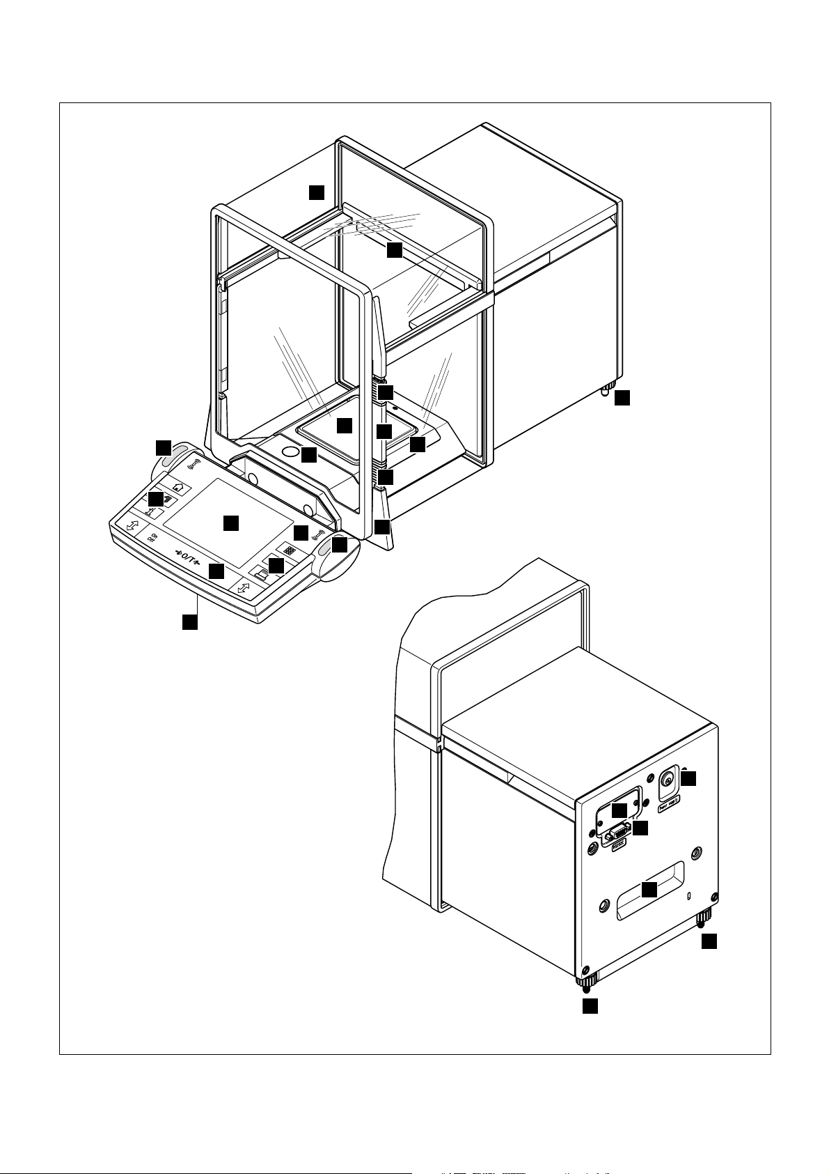
Overview of your MX/UMX balance
1
19
5
11
2
4
3
4
4
5
12
8
6
10
9
13
7
1
1 Control unit
2 Terminal (for details s. Chapter 4)
3 Display
4 Operating keys
5 SmartSens sensors
6 Cover
(cable compartment on underside of terminal)
7 Door handle
8 Glass draft shield
9 Weighing chamber plate
11 Weighing pan
11 Level indicator
12 Weighing cell
13 Leveling screw
14 Connecting socket for weighing cell
15 RS232C serial interface
16 Slot for second interface (optional)
17 Socket for AC adapter
18 Socket for control unit
19 Typename
13
12
16
C
2
3
S2
R
lance only
For connection to ba
For connection to evaluation
unit only
15
14
18
17
er supply
Pow
Page 4

Contents
4
Contents
1 Getting to know your balance .......................................................................................................................... 9
1.1 Introduction .................................................................................................................................................... 9
1.2 Introducing the AX and MX/UMX balances .......................................................................................................... 9
1.3 Conventions and symbols used in these operating instructions ............................................................................. 9
1.4 Safety first .................................................................................................................................................... 10
2 Setting up the balance ..................................................................................................................................11
2.1 Unpacking and checking the delivered items .................................................................................................... 11
2.2 Preparatory tasks .......................................................................................................................................... 11
2.3 Selecting a location and leveling the balance .................................................................................................... 12
2.4 Power supply ................................................................................................................................................ 12
2.5 Glass draft shield .......................................................................................................................................... 13
2.6 Adjusting the reading angle and positioning the terminal .................................................................................... 14
2.7 Transporting the balance ................................................................................................................................ 15
2.8 Below-the-balance weighing ........................................................................................................................... 16
3 Your first weighing ....................................................................................................................................... 17
3.1 Switching the balance on and off .................................................................................................................... 17
3.2 Carrying out a simple weighing ....................................................................................................................... 17
4 Basic operating concepts for the terminal and software .................................................................................. 18
4.1 Overview of the terminal ................................................................................................................................. 18
4.2 The display ................................................................................................................................................... 19
4.3 The software on your balance ......................................................................................................................... 20
4.4 Typical working procedure .............................................................................................................................. 22
5 System settings ........................................................................................................................................... 24
5.1 Calling up the system settings ........................................................................................................................ 24
5.2 Overview of the system settings ...................................................................................................................... 24
5.3 Settings for adjustment and test ...................................................................................................................... 25
5.3.1 Displaying the adjustment history (“History”) .................................................................................................... 25
5.3.2 Defining adjustment and test reports ................................................................................................................ 26
5.3.3 “ProFACT” fully automatic adjustment function .................................................................................................. 27
5.3.4 Defining an external adjustment weight ............................................................................................................ 28
5.3.5 Defining an external test weight ....................................................................................................................... 28
5.3.6 Entering the weight certificate designation ........................................................................................................ 28
5.3.7 Defining the weight identification ..................................................................................................................... 28
5.4 Specifiying the weighing parameters ................................................................................................................ 29
5.5 “SmartSens” settings ...................................................................................................................................... 30
5.6 Renaming the user profile ............................................................................................................................... 30
5.7 Selecting the door function ............................................................................................................................. 31
5.8 Selecting peripheral devices ............................................................................................................................ 32
5.9 Terminal settings ........................................................................................................................................... 33
5.10 Resetting to the factory settings ....................................................................................................................... 34
5.11 Date and time ............................................................................................................................................... 34
Page 5

Contents
5.12 Selecting the dialog language ......................................................................................................................... 35
5.13 Security settings ............................................................................................................................................ 36
5.14 Energy-saving function and battery change date ............................................................................................... 37
5.15 Recording the system settings ......................................................................................................................... 37
6 The “Weighing” Application .......................................................................................................................... 38
6.1 Selecting the application ................................................................................................................................ 38
6.2 Settings for the “Weighing” application ............................................................................................................. 38
6.2.1 Overview ...................................................................................................................................................... 38
6.2.2 Select function keys ....................................................................................................................................... 40
6.2.3 “SmartTrac” and stopwatch ............................................................................................................................ 41
6.2.4 Selecting information fields ............................................................................................................................. 41
6.2.5 Manual/automatic transfer of weight values ...................................................................................................... 42
6.2.6 Selecting weighing units ................................................................................................................................. 43
6.2.7 Defining custom weighing units ...................................................................................................................... 43
6.2.8 Defining the weighing record .......................................................................................................................... 44
6.2.9 Parameters for manual record printing ............................................................................................................. 46
6.2.10 Defining identifications and record titles ........................................................................................................... 47
6.2.11 Parameters for processing bar code data ......................................................................................................... 48
6.3 Working with the “Weighing” application .......................................................................................................... 48
6.3.1 Manually entering the tare preset ..................................................................................................................... 48
6.3.2 Changing the resolution of the weighing result .................................................................................................. 49
6.3.3 Specifying the target weight and tolerances ...................................................................................................... 49
6.3.4 The “SmartTrac” graphical weighing-in aid ....................................................................................................... 50
6.3.5 Weighing-in and using the statistics ................................................................................................................ 51
6.3.6 Working with identifications ............................................................................................................................ 53
6.4 Adjusting the balance and checking the adjustment ........................................................................................... 55
6.4.1 Fully automatic adjustment using ProFACT ....................................................................................................... 55
6.4.2 Adjustment using the internal weight ................................................................................................................ 55
6.4.3 Adjustment using an external weight ................................................................................................................ 56
6.4.4 Checking the adjustment with the internal weight .............................................................................................. 57
6.4.5 Checking the adjustment with an external weight .............................................................................................. 57
6.4.6 Adjustment and test records (examples) .......................................................................................................... 58
5
7 The "Percent Weighing" Application .............................................................................................................. 60
7.1 Introducing the "Percent Weighing" application ................................................................................................. 60
7.2 Selecting the application ................................................................................................................................ 60
7.3 Settings for the "Percent Weighing" application ................................................................................................. 60
7.3.1 Overview ...................................................................................................................................................... 60
7.3.2 Special function keys for percent weighing ....................................................................................................... 61
7.3.3 Special information fields for percent weighing .................................................................................................. 61
7.3.4 Additional unit for percent weighing ................................................................................................................. 62
7.3.5 Special record information for percent weighing ................................................................................................ 62
7.4 Working with the “Percent Weighing” application .............................................................................................. 62
Page 6

Contents
6
8 The “Density” Application ............................................................................................................................. 63
8.1 Introducing the “Density” application ............................................................................................................... 63
8.2 Selecting the application ................................................................................................................................ 63
8.3 Settings for the “Density” application ................................................................................................................ 64
8.3.1 Overview ...................................................................................................................................................... 64
8.3.2 Selecting the method for density determination .................................................................................................. 64
8.3.3 Selecting the auxiliary liquid ........................................................................................................................... 65
8.3.4 Special function keys for density determination ................................................................................................. 65
8.3.5 Special information fields for density determination ........................................................................................... 66
8.3.6 Special record information for density determination .......................................................................................... 67
8.3.7 Use of bar codes during density determination .................................................................................................. 67
8.3.8 Specifying the number of decimal places for the result ....................................................................................... 68
8.4 Working with the “Density” Application ............................................................................................................. 68
8.4.1 Determining the density of non-porous solids ................................................................................................... 68
8.4.2 Determining the density of liquids using a sinker ............................................................................................... 70
8.4.3 Determining the density of pasty substances using a gamma sphere................................................................... 71
8.4.4 Determining the density of liquids using a pycnometer ....................................................................................... 72
8.4.5 Determining the density of porous solids .......................................................................................................... 73
8.5 Additional functions of the “Density” application ................................................................................................ 74
8.5.1 Sample identification .................................................................................................................................... 74
8.5.2 Printing out the result of a density determination ............................................................................................... 75
8.5.3 Using the density statistics ............................................................................................................................. 76
9 The “Minimum Weighing” Application ........................................................................................................... 77
9.1 Introducing the “Minimum Weighing” Application .............................................................................................. 77
9.2 Selecting the application ................................................................................................................................ 77
9.3 Settings for the “Minimum Weighing” application .............................................................................................. 78
9.3.1 Overview ...................................................................................................................................................... 78
9.3.2 Special function keys for minimum weighing .................................................................................................... 78
9.3.3 Special information fields for minimum weighing .............................................................................................. 79
9.3.4 Information menu for minimum weighing ......................................................................................................... 79
9.3.5 Special record information for minimum weighing ............................................................................................. 79
9.4 Working with the “Minimum Weighing” Application ........................................................................................... 80
10 Loading Applications via the Internet ............................................................................................................. 81
10.1 Operating principle ........................................................................................................................................ 81
10.2 Prerequisites ................................................................................................................................................. 81
10.3 Downloading the application package from the Internet ..................................................................................... 81
10.4 Loading the application package onto your balance .......................................................................................... 82
10.5 Backing up and restoring your balance settings ................................................................................................ 83
11 Further important information ....................................................................................................................... 84
11.1 Error messages occurring during normal operation ........................................................................................... 84
11.2 Further error messages .................................................................................................................................. 84
11.3 Cleaning and service ..................................................................................................................................... 85
Page 7

Contents
12 Technical data and accessories ..................................................................................................................... 86
12.1 General data ................................................................................................................................................. 86
12.2 Model-specific data ....................................................................................................................................... 87
12.3 Dimensions .................................................................................................................................................. 90
12.4 Specifications of the RS232C interface ............................................................................................................. 92
12.5 Accessories .................................................................................................................................................. 93
13 Appendix ..................................................................................................................................................... 95
13.1 Conversion table for weight units ..................................................................................................................... 95
13.2 SOPs - standard operating procedures ............................................................................................................ 96
14 Index ........................................................................................................................................................... 98
7
Page 8

Contents
8
Page 9

Chapter 1: Getting to know your balance
1 Getting to know your balance
In this chapter you will be given basic information about your balance. Please read right through this chapter carefully even if you
already have experience with METTLER TOLEDO balances; please pay special attention to the safety warnings!
1.1 Introduction
Thank you for choosing a METTLER TOLEDO balance.
The analytical balances of the AX line, and the micro and ultra-microbalances of the MX and UMX lines, combine a large number
of weighing and adjustment possibilities with exceptionally convenient operation. With these new-generation balances additional
applications and software updates can be downloaded from the Internet and loaded into the balance.
Please read right through these operating instructions carefully so that you can fully utilize all the possibilities your balance offers.
These operating instructions apply to all balances in the AX and MX/UMX lines. However, the different models have different
characteristics regarding equipment and performance. Special notes in the text indicate where this makes a difference to operation.
1.2 Introducing the AX and MX/UMX balances
9
The AX and MX/UMX family of balances comprises a range of analytical, micro, and ultra-microbalances which differ from each other
in relation to their weighing range, resolution, and equipment.
The following features are common to all models of the AX and MX/UMX lines:
– Glass draft shield with motorized opening for precise weighing even in unstable environments.
– Fully automatic adjustment (calibration and linearization) using internal weight.
– Integrated applications for normal weighings, piece counting, percent weighing, and density determination. If required, further
applications can be downloaded from the Internet onto your computer and from there onto your balance.
– Integral RS232C interface.
– Touch-sensitive graphics terminal (“TouchScreen”) for easy, convenient operation.
– Two programmable sensors for hands-off operation (“SmartSens”) to speed up frequently recurring tasks.
Now a few comments on standards, directives, and quality assurance methods. The AX and MX/UMX balances conform to the usual
standards and directives. They support standard procedures, specifications, working methods, and records according to GLP (Good
Laboratory Practice) and SOP (Standard Operating Procedure). In this connection, records of working procedures and adjustments
become very important; for this purpose we recommend you to use a printer from the METTLER TOLEDO range, since these are
optimally adapted to your balance. The AX and MX/UMX balances have a CE Declaration of Conformity, and METTLER TOLEDO is
certified as manufacturer according to ISO 9001.
1.3 Conventions and symbols used in these operating instructions
The following conventions apply throughout these operating instructions:
– The illustrations in these operating instructions are based on the AX balances. Some of the menus and reports for the MX
and UMX balances may be slightly different. If this makes a difference to operation, this is described in the text.
– Key designations are indicated by double angular parentheses (e.g. «On/Off» or «4»).
Page 10
Chapter 1: Getting to know your balance
10
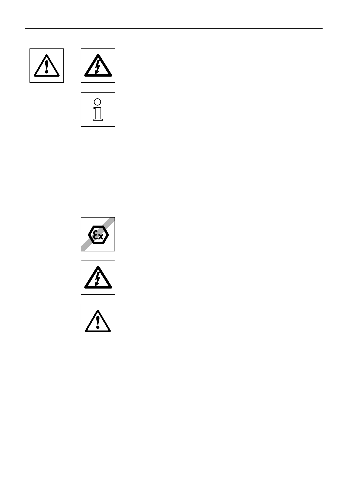
These symbols indicate safety notes and hazard warnings which, if ignored, can cause
personal danger to the user, damage to the balance or other equipment, or malfunctioning of the balance.
This symbol indicates additional information and notes which make using your balance
easier, and help you to use it correctly and efficiently.
1.4 Safety first
To ensure safe and trouble-free operation of your balance, please observe the following instructions:
Read right through these operating instructions carefully, even if you already have
experience with METTLER TOLEDO balances. Always operate and use your balance only
in accordance with the instructions contained in this manual.
The instructions for setting up your new balance must be strictly observed.
The balance may only be used in enclosed interior rooms. It is not permitted to use the
balance in hazardous environments.
Use only the AC adapter delivered with your balance, and check that the voltage printed
on it is the same as your local power supply voltage. Only plug the adapter into a socket
which is grounded.
Take care when working with toxic or radioactive substances: the automatic door
function of your balance may cause the doors to close suddenly while the balance is
being loaded and inatentiveness when this happens can cause weighing substances
to be spilt. To prevent this, if you are working with hazardous materials, switch the
automatic door function and the two “SmartSens” sensors off (see Chapter 5).
Do not use sharply pointed objects to operate the keyboard of your balance!
Although your balance is very ruggedly constructed, it is nevertheless a precision
instrument. Treat it with corresponding care, and it will reward you with many years of
trouble-free service.
Do not open the balance: it does not contain any parts which can be maintained,
repaired, or replaced by the user. If you ever have problems with your balance, contact
your METTLER TOLEDO dealer.
Use only balance accessories and peripheral devices from METTLER TOLEDO; they are
optimally adapted to your balance.
Page 11

Chapter 2: Setting up the balance
11
2 Setting up the balance
This chapter explains how to unpack your new balance, and how to set it up and prepare it for operation. When you have carried
out the steps described in this chapter, your balance is ready for operation.
2.1 Unpacking and checking the delivered items
When you receive the balance, please check that all parts have been delivered.
Open the packaging and carefully remove all the parts. The standard delivery comprises
the following items:
– AX balances: fully-assembled balance wtih terminal installed
MX/UMX balances: weighing cell and control unit with terminal installed
– AX balances: weighing pan and draft cover; MX/UMX balances: weighing pan is
installed, draft disk is delivered separately and must be installed by the user.
– AC adapter with country-specific power cable
– Connection cable for connecting the weighing cell to the control unit (MX/UMX
balances only)
– Protective cover for the terminal
– Cleaning brush
– Cleaning tweezers (MX/UMX models only)
– Weighing tweezers (not for all models)
– Production certificate
– Operating instructions (this document)
– Booklet "Weighing the right way with METTLER TOLEDO"
– Instructions for the “METTLER TOLEDO Standard Interface Command Set” (MT-SICS),
in English
Please keep all parts of the packaging. This packaging provides the best guarantee of
protection when transporting your balance (Chapter 2.7).
2.2 Preparatory tasks
The AX, MX, and UMX balances have different weighing pans and draft covers. Please observe the following instructions for installing
these parts:
AX balances: First place the draft cover in position. The small drilled hole must face to the back so that the projection on the balance
fits into the hole. The weighing pan has two notches. Place the weighing pan into position so that the notches point toward the glass
doors. If necessary, turn the weighing pan slightly until it slides down into the correct position.
MX/UMX balances: install the draft disk. The draft disk for the UMX balances comprises several parts. To install, follow the
instructions printed on the packaging of these parts.
Use the cable delivered with MX and UMX balances to connect the balance to the control unit and the weighing cell. It does not matter
which end of the cable you connect to the control unit or the weighing cell. The screws of the cable plug have drilled holes and can
be sealed to prevent the control unit and weighing cell from becoming separated.
Page 12
Chapter 2: Setting up the balance
12
2.3 Selecting a location and leveling the balance
Your balance is a precision instrument. Its accuracy and reliability depend on its being placed in an optimal location:
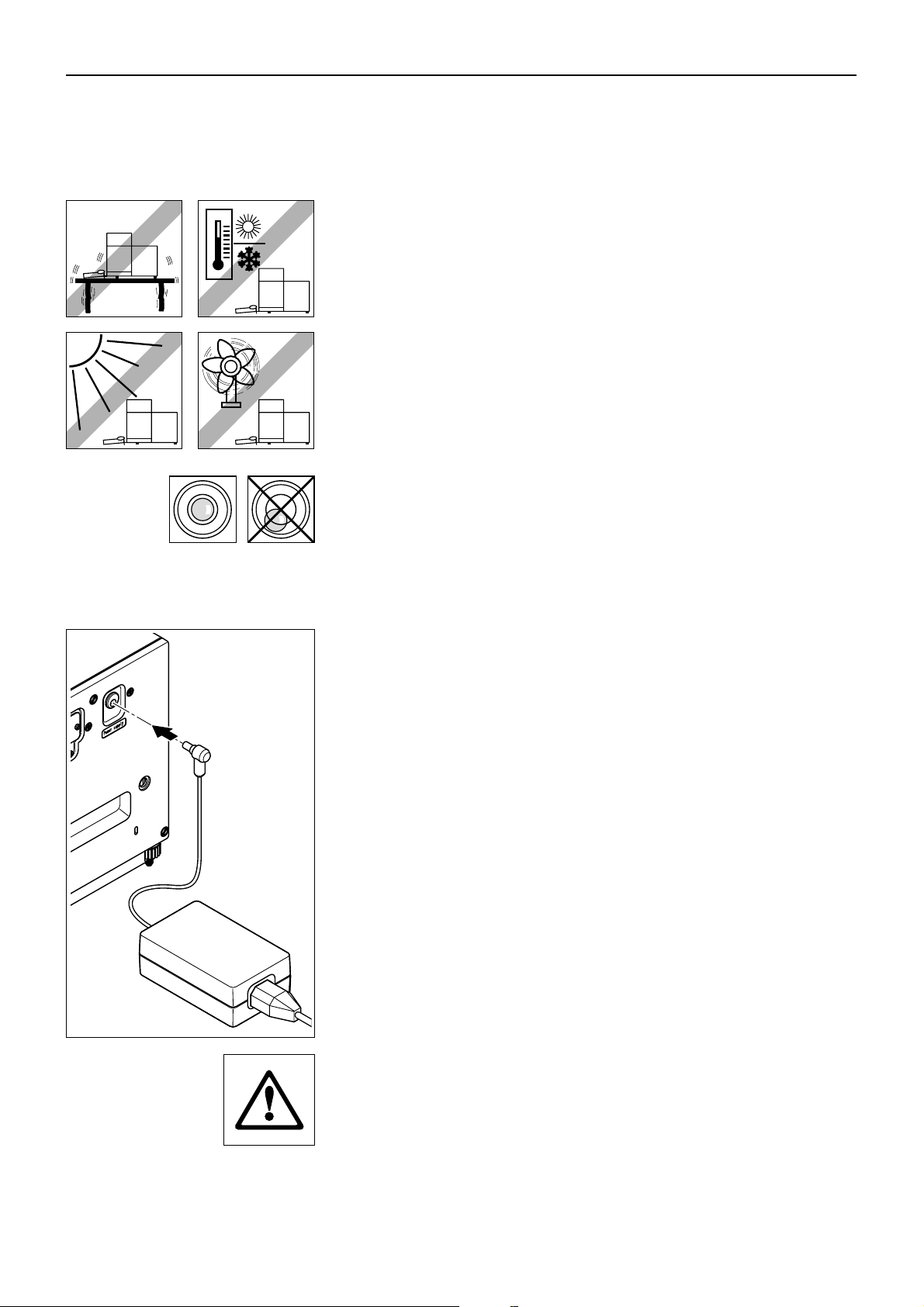
Choose a position which is stable, free from vibration, and as nearly horizontal as
possible. The supporting surface must be able to bear the weight of the fully loaded
balance safely. A stone table is recommended for MX/UMX balances.
Pay attention to the environmental conditions (see technical data).
Avoid:
– Direct sunlight
– Strong drafts (e.g. from fans or air conditioning)
– Excessive fluctuations in temperature.
Level the balance: Turn the two leveling screws at the back of the balance housing until
the air bubble of the level indicator is in the inner circle.
2.4 Power supply
Your balance is delivered complete with an AC adapter and a country-specific power
supply cable. The AC adapter is suitable for all power supply voltages in the range:
100 – 250 VAC, -10/+15%, 50 – 60 Hz.
Check that the local power supply voltage is in this range. If it is not, DO NOT connect
the balance or the AC adapter to the power supply, and contact your METTLER
TOLEDO dealer.
AX balances:
Plug the AC adapter into the socket in the back of your balance (see illustration) and
into the power supply.
MX/UMX balances:
Plug the AC adapter into the socket in the back of your control unit and into the power
supply (not illustrated).
Important: Guide the cables so that they cannot become damaged and will not be
in your way during your daily work! Take care that the AC adapter cannot come into
contact with liquids!
After the balance has been connected to the power supply, it carries out a self test and
is then ready for operation.
Page 13
Chapter 2: Setting up the balance
13
2.5 Glass draft shield
The glass draft shield of your balance can be adapted to the environmental conditions and your weighing style, as well as to the
type of weighing and loading.
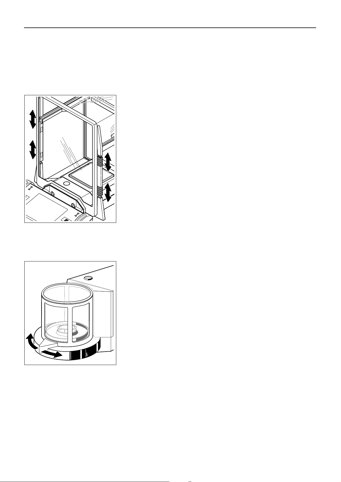
Draft shield on AX balances
The position of the coupling elements determines which parts (left-hand, right-hand,
and upper door) of the glass draft shield can be opened.
Try out various different combinations by moving the 4 coupling elements up and down.
We recommend arranging the glass draft shield in such a way that only those parts are
opened that are necessary for loading. Your balance then works faster, because the
disruptive air currents are weaker than when the glass draft shield is completely open.
The doors of the glass draft shield can be opened and closed either by means of the «2»
key, the “SmartSens” sensors, or by hand (this will be described in detail later in these
operating instructions).
Note: To open the doors by hand, the two lower coupling elements must always be
uncoupled (upper position)!
Draft shield on MX/UMX balances
The glass draft shield can be opened and closed either by means of the «2» key, the
“SmartSens” sensors, or by turning the door handle by hand. The door keys and
“SmartSens” sensors will be described in detail later in these operating instructions.
Note: The «2» key and the “SmartSens” sensor on the left-hand side of the terminal open
the draft shield for loading the balance from the right-hand side, whereas the «2» key
and the right-hand “SmartSens” sensor open the left-hand part of the draft shield.
Page 14

Chapter 2: Setting up the balance
14
2.6 Adjusting the reading angle and positioning the terminal
So that you can work without fatigue, the reading angle of the terminal can be adjusted. For delivery, the terminal is fastened to the
balance or control unit. So that you can arrange your workplace optimally, the terminal can be disconnected from the balance or
control unit and positioned separately.
Adjusting the reading angle
If you wish to have a steeper reading angle, grasp the back of the terminal and pull it
slowly upward until it clicks into the desired position. Three different setting positions
are provided.
If you wish to have a flatter reading angle, press the two stop buttons on the back of the
terminal and press the terminal downward. Release the two stop buttons and the
terminal will then click into the desired position.
Removing the terminal from the balance
Switch off the balance.
Fold the terminal upward aginst the front panel of the glass draft shield. Note: to do this,
the terminal must be in the lowest setting position (flattest reading angle).
Unscrew the knurled screw underneath the terminal and remove the cover.
Page 15
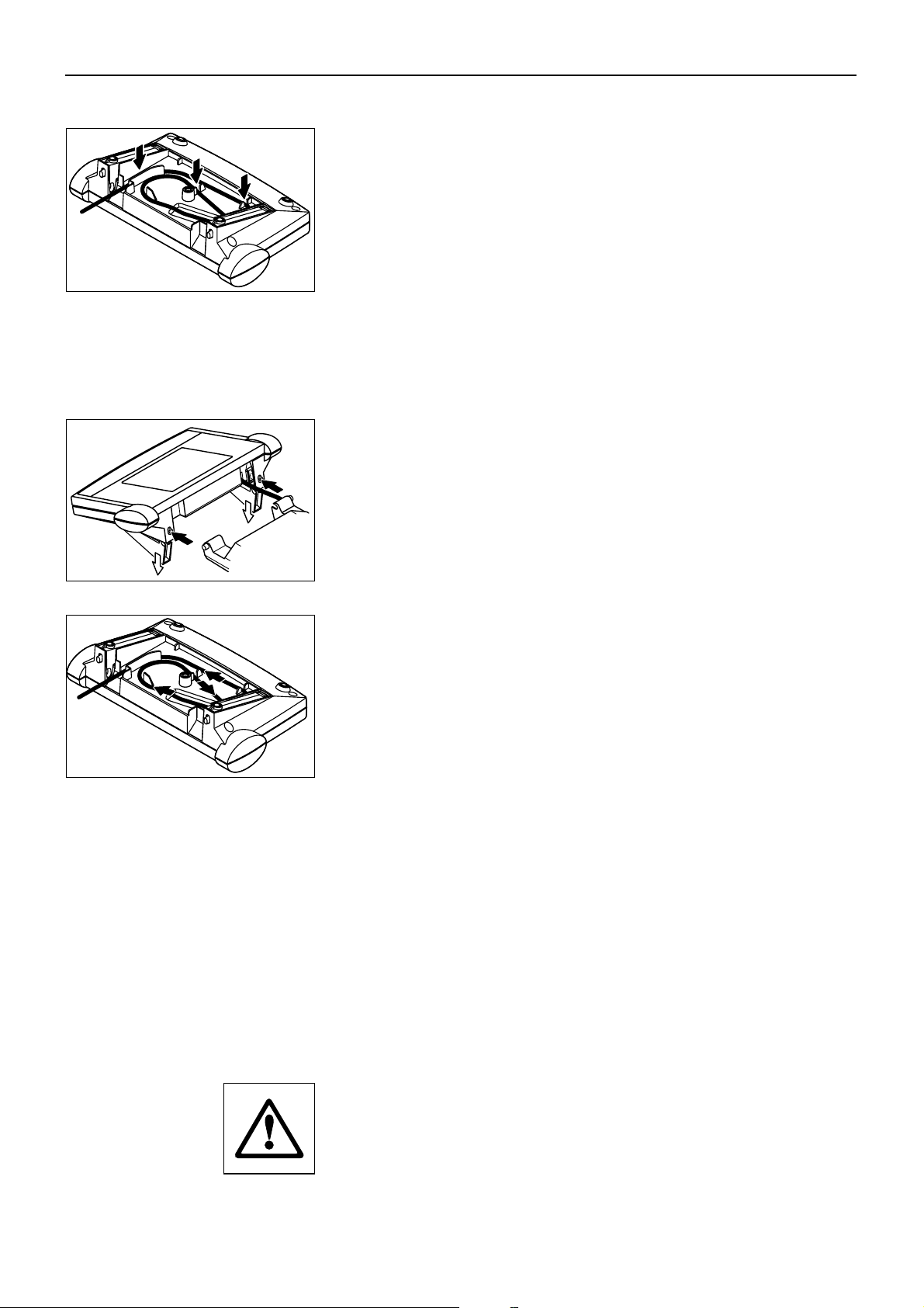
Chapter 2: Setting up the balance
15
Pull the connecting cable gently out of the tension relievers. Unwind the cable. Replace
the cover and fasten it with the knurled screw.
Fold the terminal forward again into its normal position.
Grasp the back of the terminal and pull it slowly upward until it clicks into the top position
(steepest reading angle).
Press the two stop buttons on the back of the terminal and pull the terminal further
upward. By doing this you release the two feet of the terminal from their mountings.
Place the terminal in the desired location. Press the two stop buttons and lower the feet
back into the terminal.
To fasten the terminal onto the balance or control unit again, carry out the procedure in
the reverse order. Please refer to the illustration on the left: it shows how to place the
cable correctly in the terminal housing.
2.7 Transporting the balance
If you wish to move your balance over a short distance to a new location, proceed as
follows:
AX balances
Switch off the balance and unplug the cable of the AC adapter, and any interface cables,
from the balance.
Fold the terminal upward.
Grasp the underside of the balance at the front (not the terminal!). On the back of the
balance there is a recessed handhold. Carefully lift the balance and carry it to its new
location. (Observe the notes in Chapter 2.3 regarding the choice of an optimal location).
Never lift the balance by the glass draft shield, as this can cause damage!
Page 16

Chapter 2: Setting up the balance
16
MX/UMX balances
Switch off the balance and unplug the cable of the AC adaptor, and any interface cables,
from the control unit. It is not necessary to disconnect the control unit from the weighing
cell.
Grasp the control unit and weighing cell by the sides of the housing and carry them to
their new location (observe the notes in Chapter 2.3 regarding the choice of an optimal
location).
Never lift the balance by the glass draft shield, as this can cause damage!
Transporting over long distances
If you wish to transport or ship your balance over long distances, or if it is not certain
that the balance will be tranported in a vertical position, use the complete original
packaging (internal and external packaging). For the AX balance, observe the packing
instructions which are printed on the original packaging!
2.8 Below-the-balance weighing
So that weighings can be carried out below the working surface (below-the-balance weighing), your balance is provided with a
special hanger.
AX balances
Switch off the balance and unplug the cable of the AC adapter from the back of the
balance. Also remove any interface cables. Open the glass draft shield and remove the
weighing pan and the draft cover.
Carefully tip the balance toward the back so that it comes to rest on its back.
Unscrew the screw of the cover of the hanger and remove the cover.
The balance is now ready for installing the feedthrough for below-the-balance weighing.
MX/UMX balances
Remove the glass cover, the weighing pan, and the draft disk (which on the UMX
balance is made of several parts). Remove the draft shield from the unit.
Carefully tip the weighing cell toward the back.
Turn the cover plates of the hanger for below-the-balance weighing until the drilled hole/
ring for the feedthrough for below-the-balance weighing is exposed.
The balance is now ready for installing the feedthrough for below-the balance weighing.
Page 17
Chapter 3: Simple weighing
17
3 Your first weighing
In this chapter you will get to know the operating and display elements of your balance which are necessary to carry out simple
weighings. This chapter provides a first introduction to operating your balance.
3.1 Switching the balance on and off
To switch the balance on: Briefly touch the «On/Off» key. After the balance has been
On
Off
switched on, it carries out a short test and is then ready for weighing.
When the balance is switched on for the first time, the indicator shown at the side
appears.
On
To switch the balance off: Touch the «On/Off» key and press it until “OFF” appears in
the display. The display then goes off, and the balance is switched off.
Off
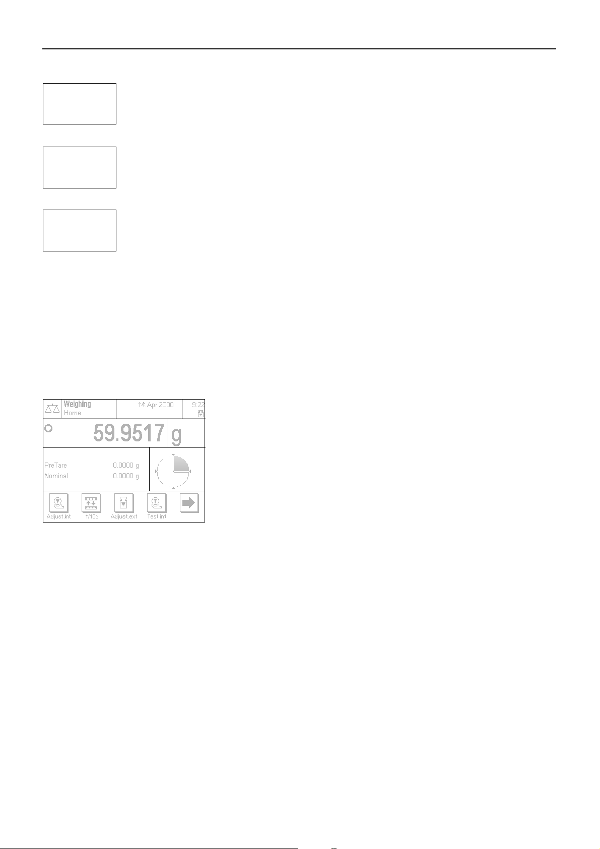
3.2 Carrying out a simple weighing
To carry out a simple weighing, you need only use the keys in the lower, dark part of the terminal.
Open the glass draft shield either by hand or by touching one of the two «2» keys. Note:
On the MX/UMX balances the «2» key on the left-hand side of the terminal opens the right-
2
1
hand side of the draft shield, whereas the right-hand «2» key opens the draft shield on
the left-hand side.
If you work with a weighing container, place it on the weighing pan and then touch the
«1» key to tare the balance and set the display to zero. The glass draft shield
closes automatically and then opens again when taring is complete.
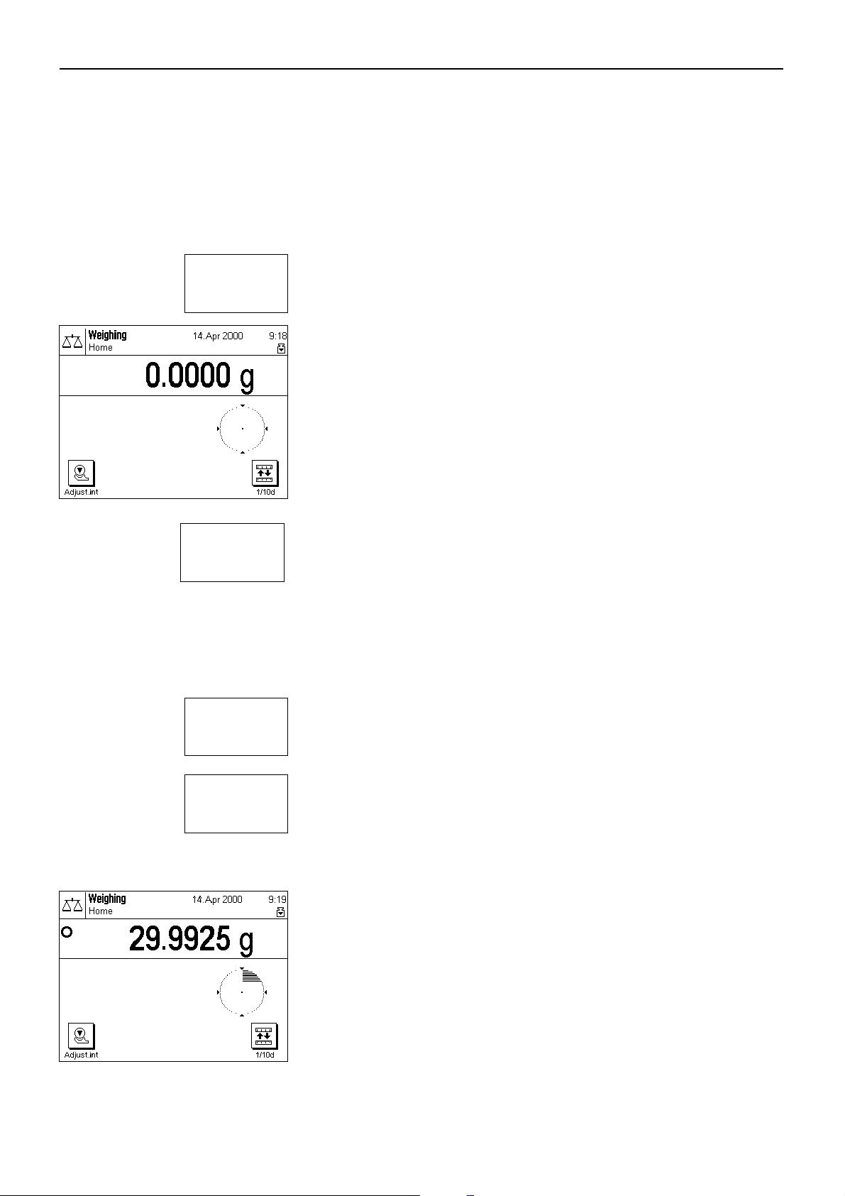
Place the sample to be weighed on the weighing pan, and close the draft shield (either
manually or using one of the «2» keys).
As soon as the stability detector symbol (the small ring to the left of the weight display)
goes out, the display is stable and you can read the weighing result. In the illustration
at the side, the stability detector symbol is still visible, and the weighing result is therefore
not yet stable.
Page 18
Chapter 4: Basic operating concepts for the terminal and software
18
4 Basic operating concepts for the terminal and software
This chapter describes the operating and display elements on your terminal and explains the concept for operating the software on
your balance. Please read right through this chapter carefully: it is the basis for all the operating steps described in subsequent
chapters.
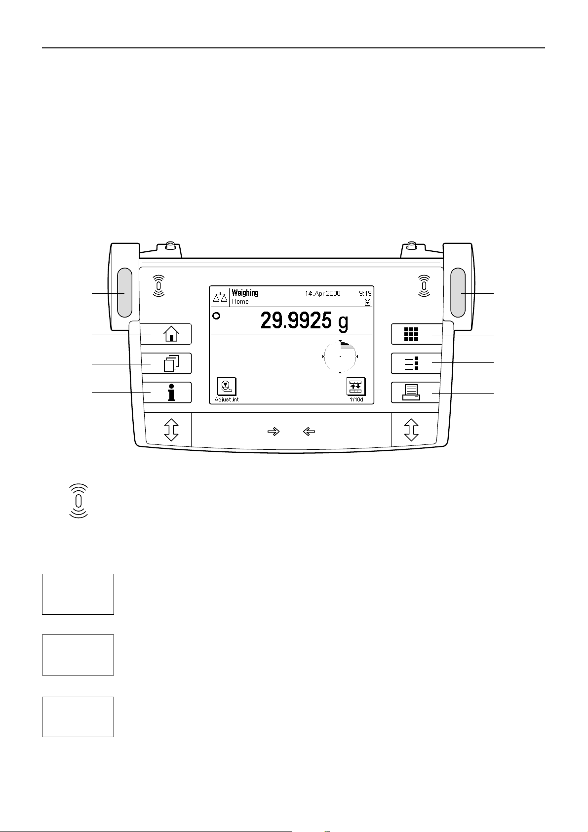
4.1 Overview of the terminal
In this section, we will first describe the operating elements of the terminal, which comprise the “SmartSens” and the individual keys.
In the next section, you will find detailed information about the display.
1
2
3
4
3
1
5
6
7
On
Off
1 SmartSens
Each of these two hands-off sensors can be given a specific function (opening and closing the glass draft
shield, or zeroing the balance). To trigger the respective function, move your hand over the corresponding
sensor at a maximum distance of approximately 5 cm. The sensor beeps to confirm that it has recognized the
command. Before leaving the factory, the two sensors are programmed to open and close the glass draft shield.
2 «3» key
You can use this key at any time to reset the current application to its starting status - in other words, to the
status it has when you first call it up (“Home” profile).
O/T
4
5
3 «4» key
This key is used to call up the desired user profile. A user profile can be used to save specific settings. This
makes it possible to adapt the balance optimally to a particular user or weighing task.
4 «5» key
With this key you can call up a context-sensitive help function at any point. The help text gives a brief
explanation of the possibilities available to you at this point (e.g. in a menu). The help window appears over
the top of the normal display.
Page 19
5 «6» key
Before leaving the factory, your balance has been programmed with standard applications (e.g. for normal
6
7
8
weighing, piece counting, and density determination). Use this key to select the application you wish to work
with.
6 «7» key
Each application has a large number of settings which can be used to adapt it optimally to the specific task.
Use this key to call up the menus to configure the currently active application.
7 «8» key
When this key is pressed, the weighing result is transmitted via the interface to, for example, a printer. However,
other devices, such as a PC, can also be connected. There are no restrictions on the data that can be
transmitted.
The keys in the dark field at the bottom edge of the terminal are for carrying out the weighings.
4.2 The display
Chapter 4: Basic operating concepts for the terminal and software
19
The illuminated graphics display of your terminal is a “TouchScreen”, or in other words, a screen which is sensitive to touch. You
can use it not only to read data and settings, but by touching the display surface you can also make settings and carry out functions.
12a
3a
2b
3b
45
6
The display is divided into a number of zones:
1 In the upper left-hand corner, the currently active application and the current user
profile are displayed. By touching this zone, you can call up a menu in which you
can select the desired application (you can also call up this menu with the «6» key).
2 In the top right-hand section, the date (2a) and time (2b) are displayed. By touching
these zones, you can change the date and time.
3 In this zone the current weighing result is displayed. If you touch this zone (3a), a
small menu appears in which you can select the font for displaying the weighing
result. If you touch the weighing unit (3b), a window opens in which you can select
the desired weighing unit.
4 This zone displays additional information (information fields), which make your
work easier. Touching this zone opens a menu in which you can specify which
information fields and function keys should be displayed (the same menu is also
available under the «7» key).
5 This zone displays the “SmartTrac”, which is a graphical weighing-in aid that shows
you at a glance how much of the weighing range has already been used and how
much is still available. By touching this zone, you can choose between various
different display styles for “SmartTrac”, turn it off completely, or include a small
stopwatch in the display.
6 This zone is reserved for the function keys, which give you direct access to frequently
used functions and settings. If more than 5 function keys are activated, you can use
the arrow keys to switch between them.
Page 20
Chapter 4: Basic operating concepts for the terminal and software
20
4.3 The software on your balance
The software controls all the functions of your balance. It also makes it possible to adapt the balance to your specific working
environment. Please read the following sections carefully; they form the basis for operating your balance.
The software comprises the following levels:
– User profiles
– Applications
– Settings
User profiles
The purpose of user profiles is to adapt the balance and its applications to your personal way of working, or
to specific weighing tasks. A user profile is a collection of settings which you can define yourself and which
are available to you at a keystroke.
When the balance is switched on, it automatically loads the “Home” profile. The “Home” profile is a starting
point to which you can return at any time by touching the «3» key. Before leaving the factory it has been
3
programmed with standard settings which all users can work with.
4
Applications
6
Settings
7
As well as the “Home” profile, 8 other user profiles are available in which you can change the settings at will.
(Two of the user profiles have been programmed at the factory for very fast and very accurate weighings and
have been given the corresponding names “Fast” and “Accurate”). You can use the «4» key to call up the
desired user profile.
Note: The “Home” profile can be changed at will in the same way as the 8 other profiles. However, we
recommend you not to change the settings in the “Home” profile that were made at the factory, but to change
one of the other 8 user profiles instead.
Applications are software modules for carrying out specific weighing tasks. A number of applications are
loaded onto the balance before it leaves the factory (e.g. for normal weighing, percent weighing, piece
counting, and density determination). When the balance is switched on, it starts the application for normal
weighing. The other applications can be accessed with the «6» key. You will find instructions for working with
the standard applications in Chapter 6 and subsequent chapters. You can also download additional
applications from the Internet if required (see Chapter 10).
The software differentiates between two sorts of settings:
– Application-dependent settings: The range of available settings differs depending on the application
selected. The multi-page menu for application-dependent settings can be accessed with the «7» key. You
will find information about the individual settings that are possible in the chapters relating to the respective
applications.
– System settings which are not application-dependent (e.g. the dialog language setting): The range of
available settings of this type is the same in all applications. To call up the system settings touch the «7»
or «6» key and then the “System” button. You will find information about the individual settings that are
possible in Chapter 5.
Both types of setting are assigned to the currently active user profile and stored with it.
Page 21
Chapter 4: Basic operating concepts for the terminal and software
21
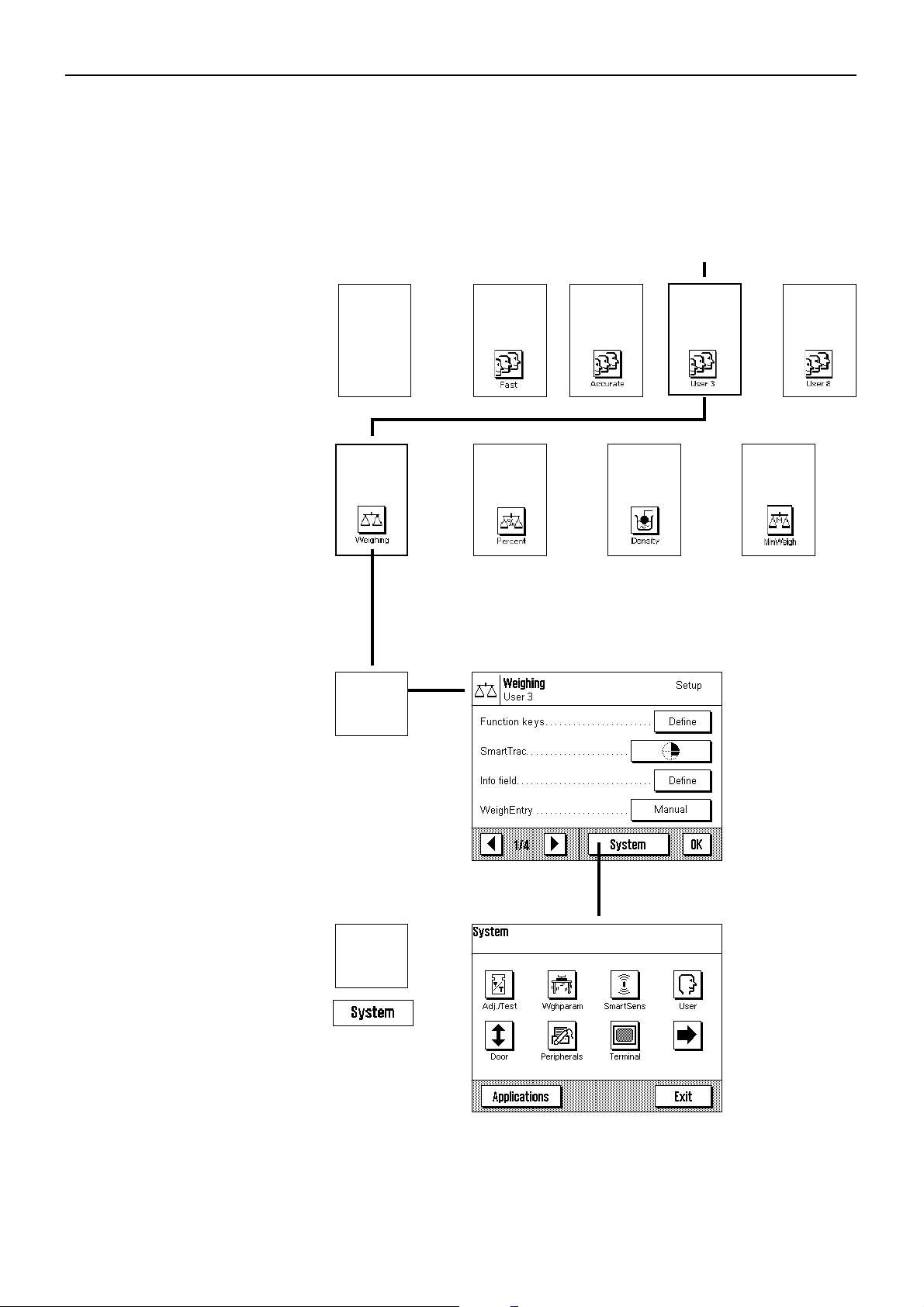
The diagram below shows the interrelationships between the individual levels of the software and gives a first overview of the typical
procedure for operating it.
Work step
1. Select user profile
2. Select application
3. Work
4. If desired:
Change the settings for the selected application (applicationdependent settings)
3
“Home”
▼
6
▼
7
Example
▼
or
or
4
6
▼
4
or
6
•
4
or
.......
Settings for the selected application
(the example
shows “Weighing”)
are stored in the
active user profile
(in the example,
“User 3”).
4
6
5. If desired:
Change the system settings
▼
7
Settings are stored
in the active user
profile (in the example, “User 3”).
Page 22
Chapter 4: Basic operating concepts for the terminal and software
22
4.4 Typical working procedure
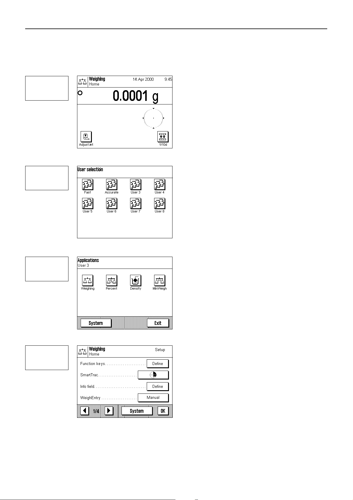
Following below is a brief description of the typical working procedure, leaving out details which depend on specific applications.
Switch on the balance: Switch on the balance by briefly pressing
On
Off
4
the «On/Off» key. After the balance has been switched on, it is in
the “Home” profile of the “Weighing” application. Important:
While you are working, you can return to the “Home” profile at
any time by touching the «3» key.
Note: Depending on the settings you have selected, the display
on your balance may differ from the example shown.
Select user profile: If you wish to use one of the 8 other user
profiles instead of the “Home” profile, use the «4» key to call up
the profile menu and then select the desired user profile by
touching the corresponding symbol. By doing this you activate
the settings stored in the selected profile for the applications and
for the system.
Note: When the balance leaves the factory, the first two user
profiles contain settings for very fast and very accurate weighings
and are given corresponding names (“Fast” and “Accurate”).
6
7
Select application: If you do not wish to work with the weighing
application, use the «6» key to select the applications menu.
(Alternatively, you can touch the corresponding zone in the top
left-hand corner of the display). Touch the symbol for the desired
application and the software will load the application.
Change settings: If you wish to change settings, press the «7»
key. The software differentiates between two types of settings:
– Application-dependent settings apply for the selected appli-
cation and are stored in the active user profile. Check that the
desired user profile and corresponding application are active
before you change any settings! You will find information
about the application-dependent settings together with the
description of the respective application (Chapter 6 and
subsequent chapters).
Page 23

7
5
Chapter 4: Basic operating concepts for the terminal and software
23
– System settings apply for the entire weighing system and for
all applications. They are also stored in the active user profile
(which is shown in the title line). Check that the desired user
profile is active before you change any system settings!
Note: The system settings can also be accessed from the
application menu («6» key). The system settings are described in detail in Chapter 5.
Weighing: Carry out the desired weighing procedures. You will
find information about working with the individual applications
in Chapter 6 and subsequent chapters.
Use "Help" function: If at some point in your work you are unsure
about the possibilities you have available, touch the «5» key
(help function). A window appears with a brief help text.
On
Off
Touching “OK” closes the help window and you can continue
with your work.
Switch off balance: When you have finished your work, switch
off the balance by touching the «On/Off» key for a few seconds.
Page 24
Chapter 5: System settings
24
5 System settings
In this chapter you will learn how you can adapt the weighing system to your requirements. There are system settings for each user
profile, as well as for the “Home” profile. As long as a particular user profile is active, its system settings apply irrespective of which
application is being used. Note: You will learn the settings for the different applications when the applications are described.
5.1 Calling up the system settings
If you do not want your settings to be used as the “Home” profile, use the «4» key to select one of the 8 user profiles.
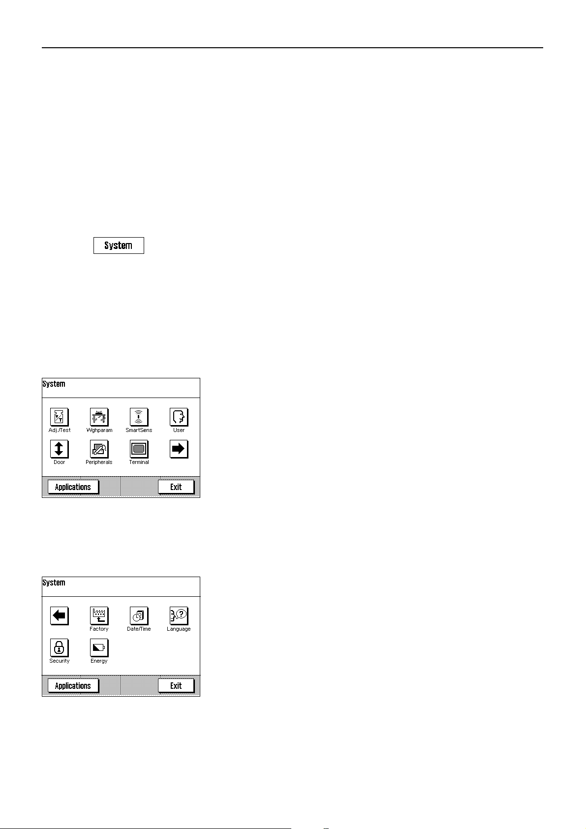
You can call up the menu for the system setting either from the settings menu
(key «7») or from the application menu (key «6»). In both menus, the “System” button
can be used for this purpose .
5.2 Overview of the system settings
The system settings are represented by symbols. By clicking on the symbols you can call up the individual settings and change them.
The various possible settings are described in the sections following below.
The following system settings are available:
“Adjust/Test”: Setting for adjustment (calibration), and for the test function
to check the adjustment (Section 5.3).
“Weighing Parameters”: Settings for adapting the balance to specific weighing tasks
(Section 5.4).
“SmartSens”: Programs the two “SmartSens” sensors (Section 5.5).
“User”: Assigns a name to the user profile (Section 5.6).
“Door”: Settings for opening the glass draft shield (Section 5.7).
“Peripherals”: Configures the interface for various peripheral devices
(Section 5.8).
“Terminal”: Settings for the display (brightness, etc.) and for the behavior
of the terminal (Section 5.9).
By touching the button with the arrow symbol, you change over to the second menu
page.
“Factory”: For resetting to the factory settings (Section 5.10).
“Date/Time”: To input the date and time, and select the desired display format
(Section 5.11).
“Language”: To select the dialog language for user guidance (Section 5.12).
“Security”: To assign a password and for balance identification (Section 5.13).
“Energy”: Settings for standby mode and to display the next date for
replacing the battery (Section 5.14).
By touching the button with the arrow symbol, you can return to the first menu page.
When you have made all the necessary settings, touch the “Exit” button to return to the
application. We will explain the various system settings, and how to use the application,
in the sections that follow below.
Page 25
5.3 Settings for adjustment and test
You can use these menus to make all the settings associated with adjusting (calibrating) your balance.
In the sections below you will find information on all the possible settings for adjustment
and test procedures and for recording them.
Chapter 5: System settings
25
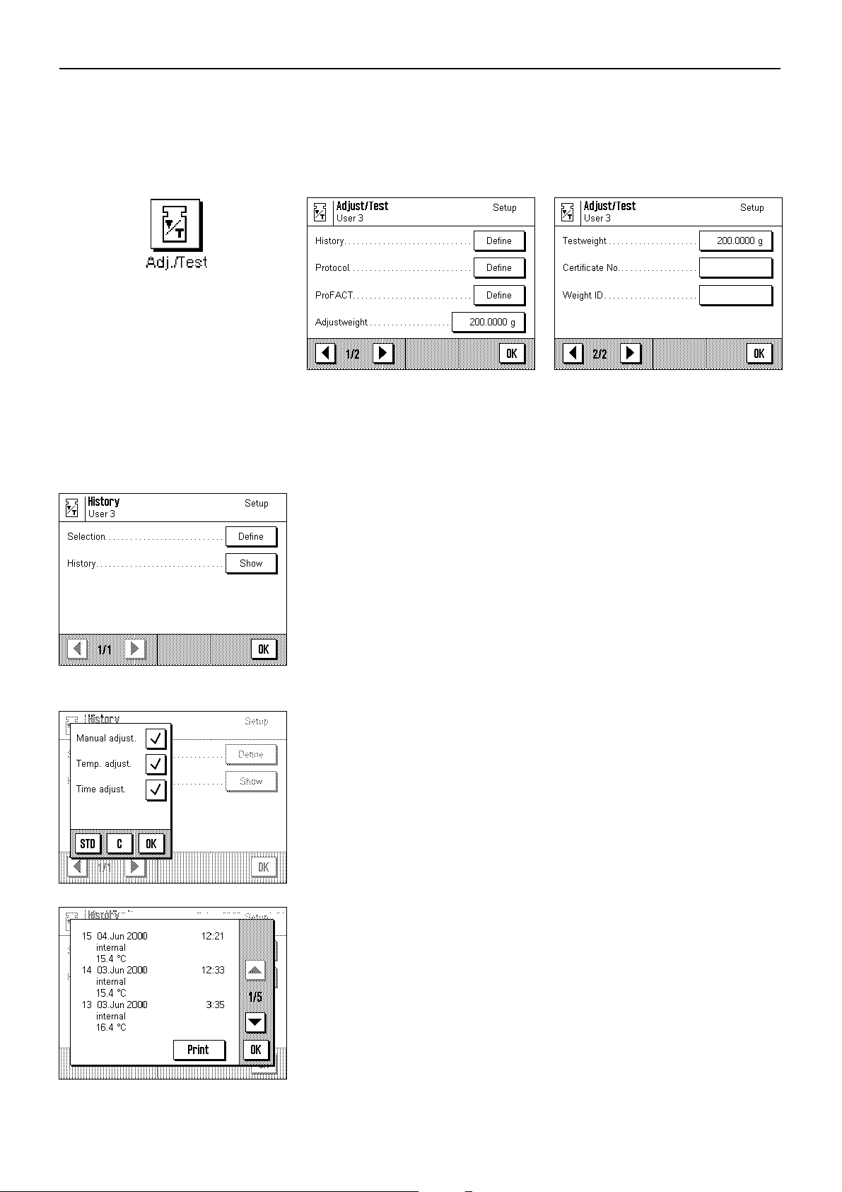
5.3.1 Displaying the adjustment history (“History”)
In the “History” menu you can call up information on adjustment procedures which have
already been carried out, and print out corresponding reports.
The balance constantly records the data and results of all adjustment procedures. The
last 25 procedures can be displayed and printed out.
The following settings are available:
“Selection”
By touching the “Define” button you call up a menu in which you specify which
procedures should be displayed. You can display manual adjustments, temperaturecontrolled adjustments, and/or time-controlled adjustment processes. The procedures
indicated with a check mark will be displayed.
Factory setting: All display options are selected.
“History”
If you touch the "Show" button, the selected adjustment procedure is displayed. The
display shows the date, time, type of adjustment made, and ambient temperature at the
time of the adjustment. You can use the arrow buttons to page up and down between
the individual pages (the most recent adjustments are shown at the top of the list, the
oldest at the bottom). You can use the “Print” button to print out all adjustments (you
will find an example of a report in Section 6.6.6). You can terminate the display by
touching “OK”.
Page 26
Chapter 5: System settings
26
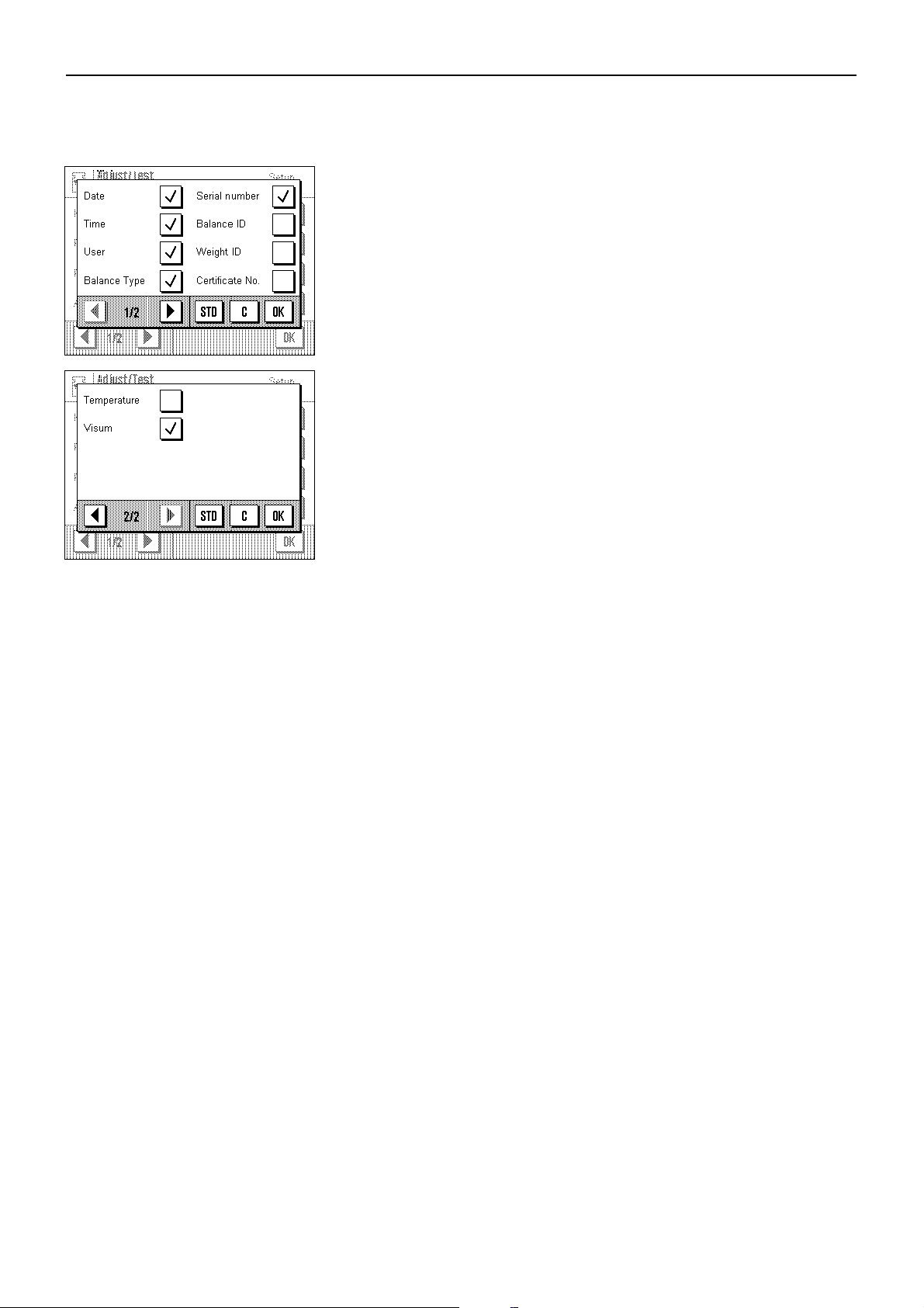
5.3.2 Defining adjustment and test reports
In this menu, which has two pages, you can specify the information to be printed on
the adjustment and test reports.
By touching the appropriate buttons, you can activate the desired information. The
checked items of information will be included on the reports. By touching “STD” you can
return to the factory settings. To save the changes, touch “OK”, (or touch “C” to quit
the input window without saving the changes).
Factory settings: The options shown checked in the illustration on the left.
The following items of information can be included in reports:
“Date”
Prints the date of adjustment in the defined date format (Section 5.11).
“Time”
Prints the time of adjustment in the selected date format (Section 5.11).
“User”
The active user profile is printed on the reports.
“Balance Type”
This information is stored in the balance and cannot be changed by the user.
“Serial number”
This information is stored in the balance and cannot be changed by the user.
“Balance ID”
Prints the specified balance identification (Section 5.13).
“Weight ID”
Prints the specified identification of an external adjustment weight (Section 5.3.7).
“Certificate No.”
Prints the specified designation for the certificate of an external adjustment weight
(Section 5.3.6).
“Temperature”
Prints the temperature at the time of adjustment .
“Visum”
Prints an additional line for signing the report.
Page 27
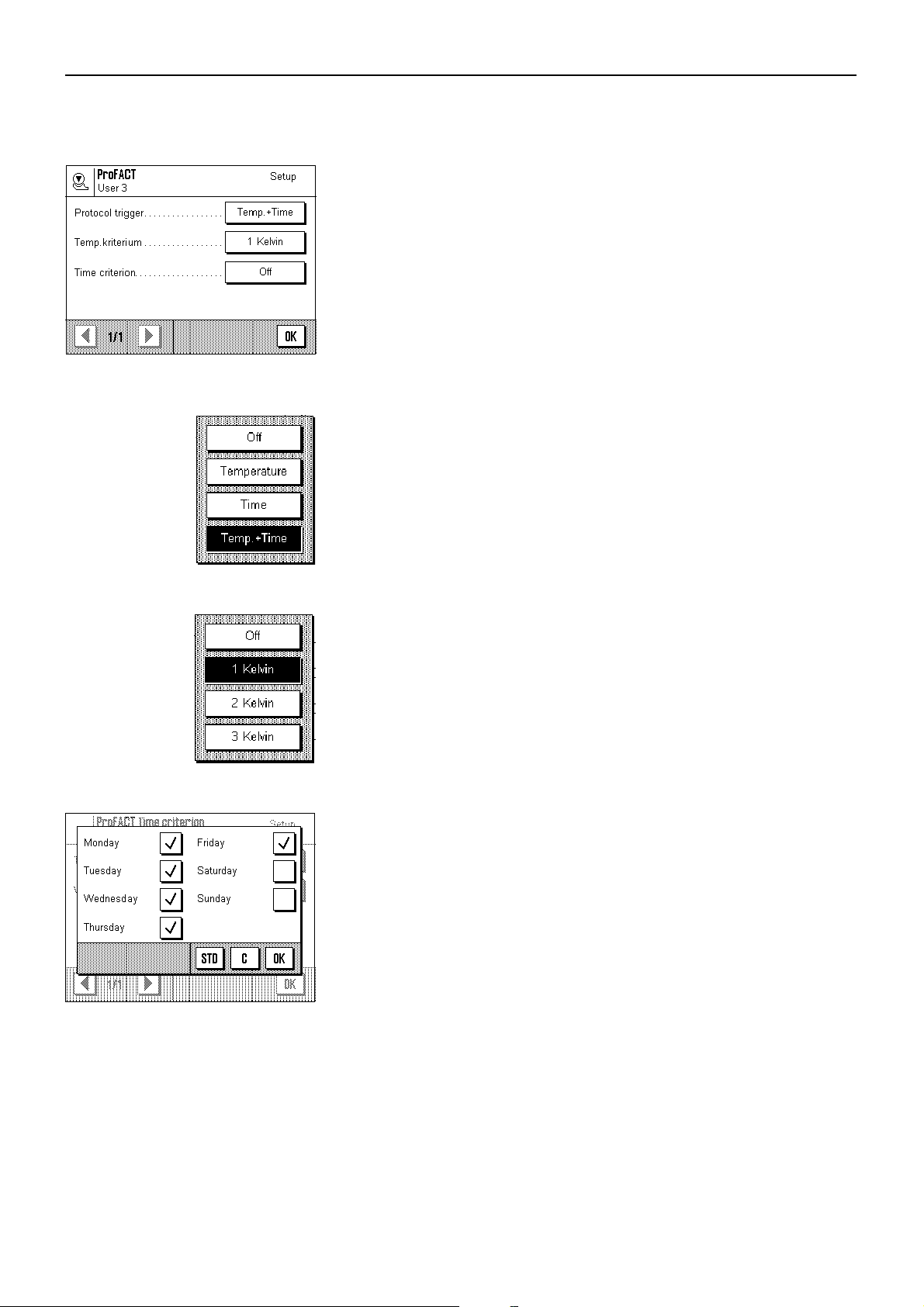
5.3.3 “ProFACT” fully automatic adjustment function
In this menu you can specify the settings for fully automatic adjustment (calibration)
using the internal adjustment weight (“ProFACT”). ProFACT adjusts the balance fully
automatically on the basis of pre-selected criteria.
The following settings are available:
“Protocol trigger”
Here you specify which adjustment procedures should be automatically printed on the
report. You can select time- and/or temperature-controlled adjustment procedures to be
automatically reported. If you select “Off”, automatic reporting does not take place.
Chapter 5: System settings
27
“Temp. criterion”
Here you define what change in the ambient temperature should trigger an automatic
adjustment. If you select “Off”, no automatic adjustment takes place in response to a
temperature criterion.
“Time criterion”
If you activate the time criterion, you can specify at what time, and on which days of
the week, an automatic adjustment should be carried out.
Factory settings: “Protocol trigger”: “Temp. + Time”
“Temp. criterion”: “1 Kelvin”
“Time criterion”: “Off”
Note: If you wish to switch off the “ProFACT” fully automatic adjustment function, you
must deactivate the temperature and time criteria (“Off”).
Page 28
Chapter 5: System settings
28
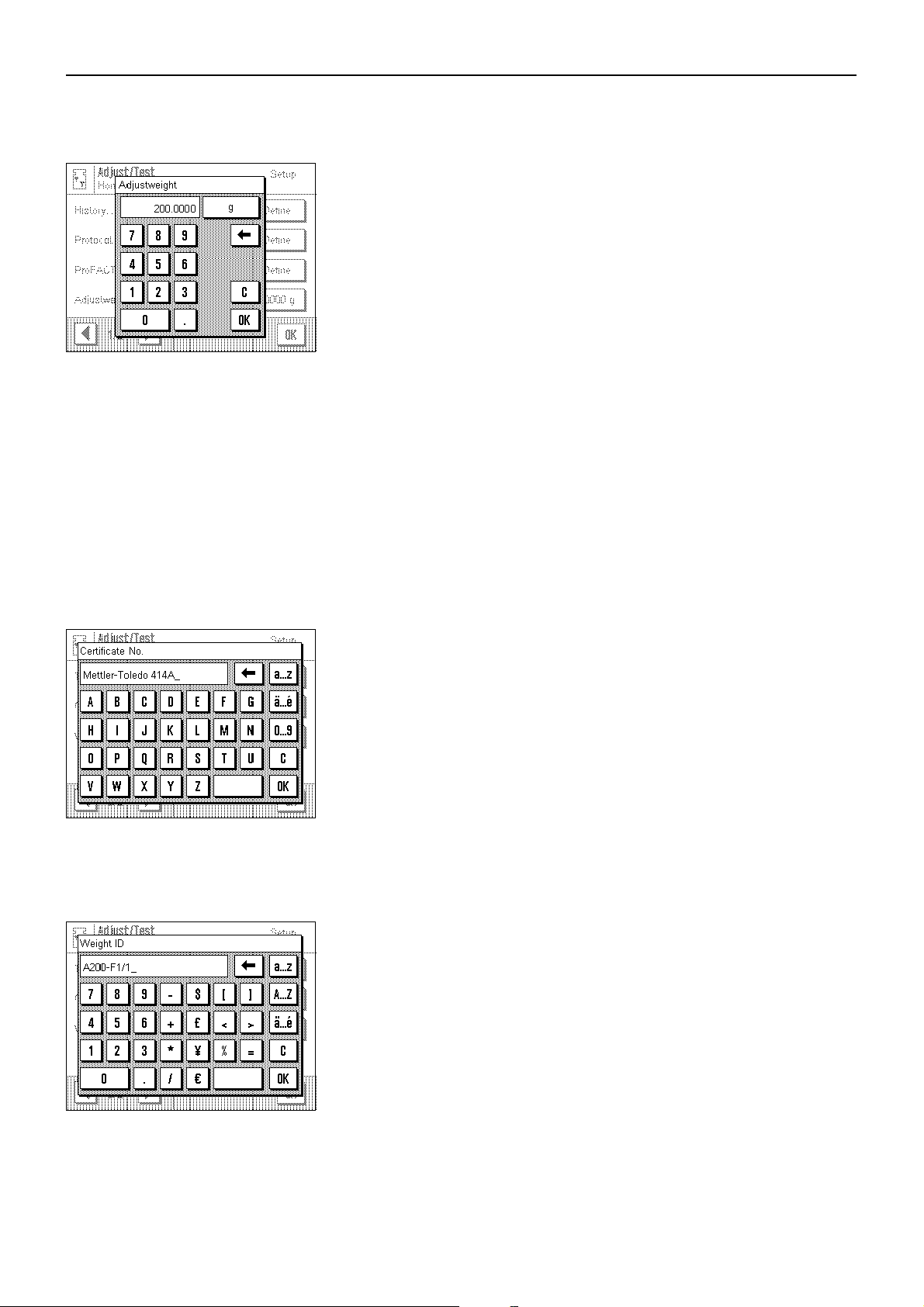
5.3.4 Defining an external adjustment weight
If you work with an external adjustment weight, you can define its weight and unit here.
(Note: Depending on country-specific regulations, this function may not be available
for certified balances). An input window appears which looks like a pocket calculator
and can be used like one. Enter the weight of the external adjustment weight. Check the
weighing unit: it is shown to the right of the weight. If you touch the weighing unit, the
selection of available units appears.
Note: The units are not automatically converted, i.e. once you have input a value in a
particular unit, this value is unchanged, even if you change the weighing unit.
Factory setting: Depends on model
5.3.5 Defining an external test weight
If you work with an external weight to check the adjustment, you can define its weight
and unit here. The same input window appears as for the external adjustment weight.
Factory setting: Depends on model
5.3.6 Entering the weight certificate designation
Adjustment weights are generally delivered with a certificate. You can enter the
designation and/or number of the certificate delivered with the weight here (max. 20
characters). This makes it possible to unambiguously link the adjustment weight used
to a specific certificate. The certificate designation is then printed out on the adjustment
record. The input window allows input of alphanumeric characters.
Factory setting: None
5.3.7 Defining the weight identification
Here you can assign a designation to the adjustment weight used (max. 20 characters). This makes identifying the adjustment weight easier. The weight identification is
then printed on the adjustment report. The same alphanumeric input window appears
as for the certificate designation.
Factory setting: None
Page 29
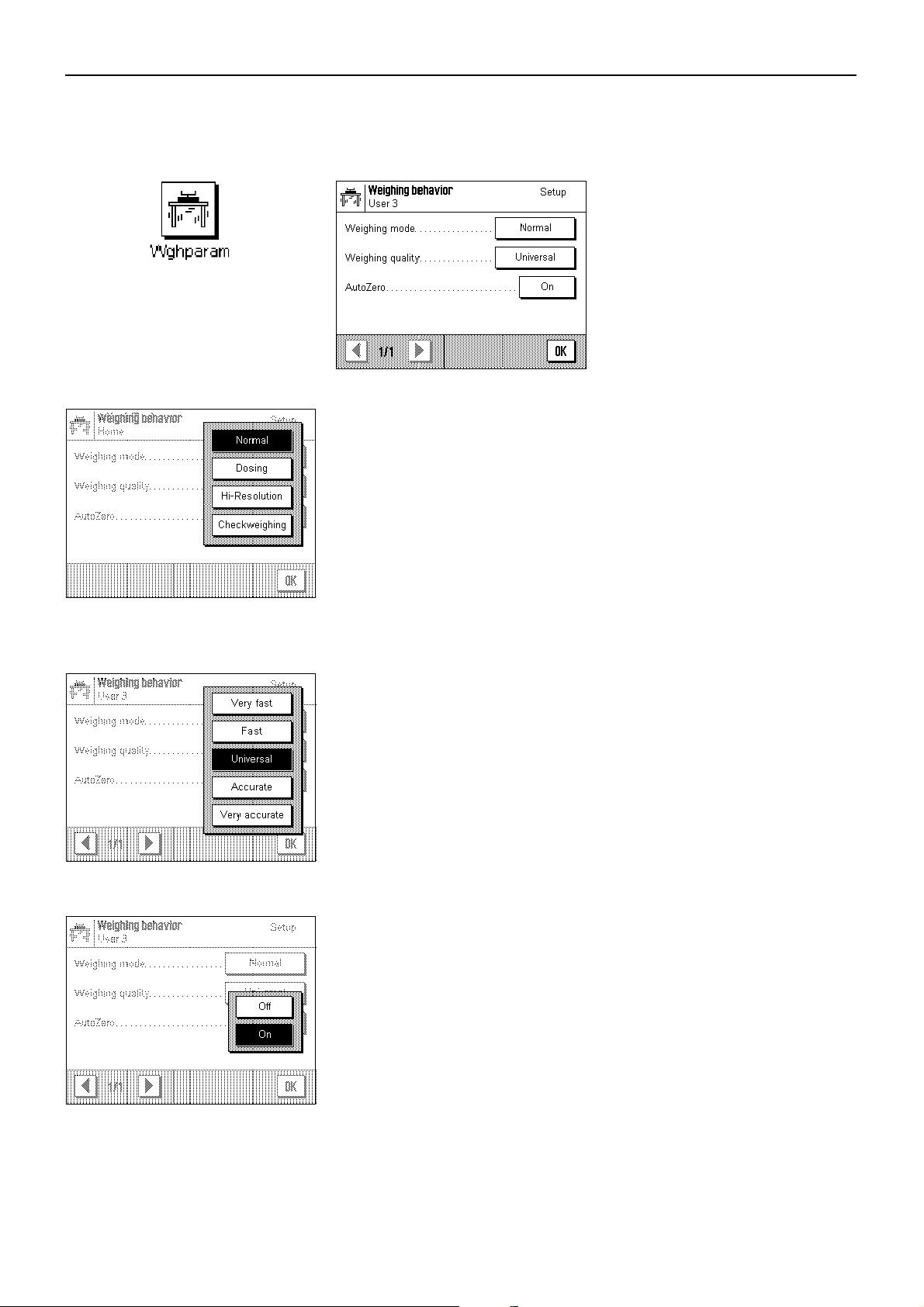
5.4 Specifiying the weighing parameters
“Weighing mode”
You can use this setting to match the balance to the type of weighing. Select weighing
mode “Normal” for all normal weighing processes, or “Dosing” for dispensing liquid or
powdery weighing samples. With this setting the balance responds very quickly to
minutest changes in weight. The “Hi-Resolution” setting is not available on all balances.
It is suitable for weighing procedures where highest possible precision is required, and
speed of weighing is of secondary importance (e.g. when weighing with comparator
balances). When the “Absolute weighing” setting is used, the balance only responds
to large changes in weight, and the weighing result is very stable.
Factory setting: “Normal”
Chapter 5: System settings
29
“Weighing quality”
You can use this setting to specify whether speed or precision of weighing has first
priority. If it is most important to have the result available rapidly, select “Very fast”. On
the other hand, if weighing accuracy has first priority, select “Very accurate”. In between,
3 other settings are available.
Factory setting: “Universal”
“AutoZero”
This switches auto-zeroing (“AutoZero”) on and off. If auto-zeroing is switched on, the
balance continually corrects any zero point drift that may occur.
Factory setting: “On” (= switched on)
Page 30
Chapter 5: System settings
30
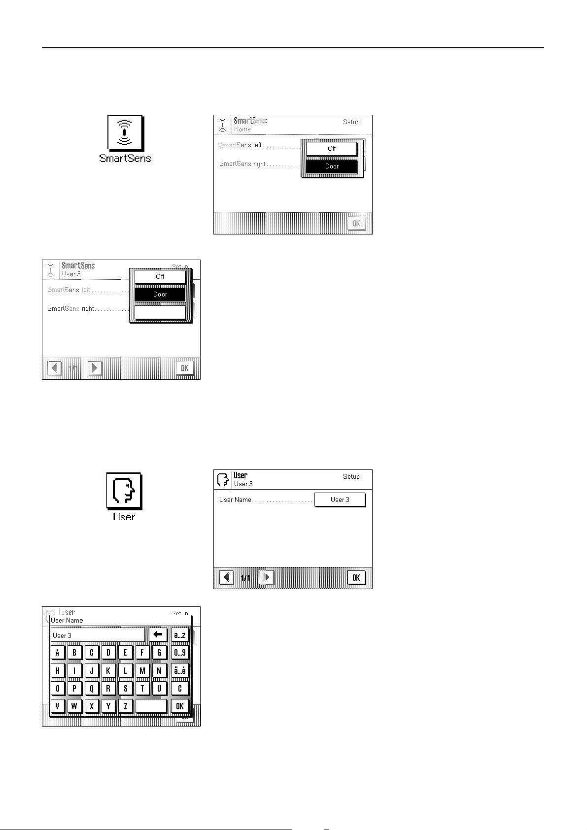
5.5 “SmartSens” settings
1
“SmartSens left”, “SmartSens right”
You can use this setting to define the function of the left-hand and right-hand
“SmartSens” sensors.
–“Off”: SmartSens is inactivated
–“Door”: Opens/closes the glass draft shield (on MX/UMX balances you can also
choose whether the draft shield should open to the left or right).
–“1”:Resets the display to zero
Factory setting: “Door” (for both sensors)
Note: In setting mode (menus), SmartSens is always inactivated.
5.6 Renaming the user profile
“User Name”
Here you can change the name of the current user profile. Both large and small letters,
as well as figures, can be used for the name. The maximum length for the name is 20
characters. Use a name for the user profile that allows unambiguous identification.
Factory setting: “Fast”, “Acurate”, “User X” (“X” = 3 – 8)
Note: At the factory, the first two user profiles have already been given settings for very
fast and very accurate weighing, respectively. So that this is immediately clear, these
two profiles have been given the names “Fast” and “Accurate”.
Page 31

5.7 Selecting the door function
“Door Function”
The automatic door function eases your work by making the doors of the glass draft
shield open or close automatically whenever specific functions require them to do so.
For example, the glass draft shield opens automatically after zeroing or taring, and
prompts you to put the material for weighing, or the tare weight, onto the weighing pan.
The door function is also activated during adjustment with an external weight, and when
checking this, or when carrying out series weighings. If you prefer to operate the glass
draft shield by using the «2» key, or the “SmartSens” sensors, or by hand, you can
deactivate the automatic door function.
Factory setting: “Automatic”
Chapter 5: System settings
31
Page 32

Chapter 5: System settings
32
5.8 Selecting peripheral devices
Various peripheral devices can be connected to your balance. In this menu you can
specify which device should be connected. Important: In contrast to the other system
settings, these settings apply to all user profiles.
The following settings can be selected:
–“Printer”: Printer
–“Host”: External computer (bidirectional commounication: the
–“Secondary display”: Secondary (auxiliary) display
–“Bar code”: Bar code reader
balance can send data to the PC and receive commands
or data from it)
The same settings are available for each of these devices. “Off” means that no device
of this type should be connected to the RS232C interface. “RS232 fixed” activates the
interface for the selected device. Important: You can only activate one single device
(“RS232 fixed”), all other devices must be deactivated (“Off”). If you activate another
device, the device that was formerly selected is automatically deactivated.
If you have activated a device, you can use the “Define” button to set the interface
parameters for communication with this device (baud rate, parity, handshake, end-ofline characters, and font). The parameters are preset for the correspondingly optimal
METTLER TOLEDO devices (for accessories and options, see Chapter 12).
Note: No interface parameters can be defined for the “Secondary display” setting: they
are preset to fixed values.
Factory setting: “Host”
(9600 baud, 8 data bits/no parity, XON/XOFF protocol,
end-of-line characters <CR><LF> ANSI/WINDOWS-font)
Important: When connecting a METTLER-TOLEDO printer, the “IBM/DOS” character set
must be selected, so that special characters (e.g. “ºC”) can be correctly printed.
Page 33

5.9 Terminal settings
Chapter 5: System settings
33
“Brightness”
Here you can set the brightness of the display. Touch the arrow buttons to adjust the
brightness in the range 0% to 100% as required. Each time one of the two arrow buttons
is touched, the brightness is instantly adjusted so that the change can be seen
immediately.
Factory setting: 80%
“Contrast”
Sets the contrast of the display in the range 0% to 100%. Adjustment is done in the same
way as for brightness.
Factory setting: 50%
“Font”
Selects the font for displaying the weighing result. There is a choice of 3 fonts.
Note: You can also make this adjustment directly in weighing mode by touching the
weighing result. A window appears in which you can select the font directly.
Factory setting: Round letters (first setting at top of list)
“Beep”
Sets the volume of the beep in the range 0% to 100%. Setting to 0% switches the beep
off. To make the setting, there is a sliding adjuster similar to those for setting the
brightness and contrast.
Factory setting: 75%
“Touch Function”
If you switch off the touch function for the “Touch Screen”, the display no longer responds
to touch in weighing mode, and so you can no longer make settings by touching the
display (exception: function keys). Important: In setting mode the touch function is
always active, because otherwise you can no longer make any settings.
Factory setting: “On”
Page 34

Chapter 5: System settings
34
5.10 Resetting to the factory settings
Here you can reset all the settings to the factory settings. Important: Resetting affects
all the settings (application-dependent settings and system settings) for the active
user profile!
If you select “Set”, for safety reasons you will be asked whether you really want to reset
to the factory settings. Select either “OK” to reset to the factory settings or “C” to keep the
existing settings.
5.11 Date and time
Important: In contrast to the other system settings, the settings for date and time
apply to all user profiles!
“Date Format” (for the display)
The following date formats are available:
“D.MMM.YYYY” Example: 4. DEC 1999
“MMM D YYYY” Example: DEC 4 1999
“DD.MM.YYYY” Example: 04.12.1999
“MM/DD/YYYY” Example: 12/04/1999
Factory setting: “D.MMM.YYYY”
Page 35

Chapter 5: System settings
35
“Date”
Sets the current date. An input window appears which looks like a pocket calculator and
can be used like one. Enter the current date in format day–month–year (DD.MM.YYYY),
irrespective of which date format you selected for the display.
Note: You can also make this adjustment directly in weighing mode by touching the
date. A window appears in which you can enter the date directly.
“Time Format” (for the display)
Here you can specify the format to be used for displaying the time. The following time
formats are available:
“24:MM” Example: 15:04
“12:MM” Example: 3:04 PM
“24.MM” Example: 15.04
“12.MM” Example: 3.04 PM
Factory setting: “24:MM”
“Time”
Sets the current time. Enter the current time in 24-hour format (hh.mm.ss), irrespective
of the time format you selected for the display. The input window is the same as for the
date, except that there are two additional buttons “+1H” and “–1H” which can be used
to put the time forward or back by one hour respectively. This makes it possible to
change over quickly to summer time or winter (standard) time. Note: You can also set
the time directly in weighing mode by touching the time in the display.
5.12 Selecting the dialog language
Here you can select the language in which you wish the balance to communicate.
Factory setting: Depends on the language package which has been installed.
The factory setting is usually the language of the destination
country.
Page 36

Chapter 5: System settings
36
5.13 Security settings
“Password”
Here you can specify the password for the current user profile. The password protects
the following areas of the current user profile:
– Access to the system settings
– Calling up the user profile.
If one of these areas is called up, the corresponding password must first be entered.
Note: If a password is defined for the “Home” profile, it only protects access to the system
settings.
The password consists of a sequence of up to 10 characters. You can use the “Clear”
button to delete the current password and thereby deactivate password protection. If no
password is specified, “no password” appears in the display.
Warning: Make a note of your password! If you forget it, contact your METTLER TOLEDO
dealer.
Factory setting: No password
“Balance ID”
Here you can assign an identification to the balance (up to a maximum of 20
characters). This can be used, for example, to identify the balance within a network. The
balance identification is also printed out on adjustment records and weighing reports.
This makes it possible to link the records and reports to a specific balance.
Factory identification: No balance identification
Page 37

5.14 Energy-saving function and battery change date
“Standby”
Here you can specify how long the balance can remain unused before it switches over
to “Standby” mode. “Standby” mode is the same status as when the balance is switched
off with the «On/Off» key. To switch the balance on again, the «On/Off» key has to be
pressed.
Factory setting: “Off” (“Standby” mode deactivated)
Chapter 5: System settings
37
“Battery change”
Your balance has a memory which is protected by a battery so that all the settings are
saved even if the balance is disconnected from the power supply. The average service
life of the battery is about 5 years. The battery can only be changed by a service
technician. After the battery has been changed, the service technician enters the date for
the next battery change. When this date is reached, the battery symbol appears under
the time display in weighing mode to remind you that the battery should be replaced.
You cannot make any changes in this field: you can only check the date when the next
battery change is due.
5.15 Recording the system settings
-------------------- Adj./Test
History
Selection
Manual adjust.
Temp. adjust.
Time adjust.
Protocol
Date
Time
User
Balance Type
When you are working in the system settings you can print them out at any time by
touching the «8» key (provided a printer is connected and activated in the peripheral
settings as output device).
The system settings printed are those for the currently active user profile.
The illustration at left shows part of a record of the system settings.
Page 38

Chapter 6: The “Weighing” application
38
6 The “Weighing” Application
In this chapter we will introduce you to the “Weighing” application. You will find information for practical work with this application,
and about the application-specific settings that are available (you will find information about non-application-specific system settings
in Chapter 5).
6.1 Selecting the application
If the “Weighing” application is not already active, touch the «6» key. In the selection
window, touch the symbol for the “Weighing” application. The balance loads the
6
6.2 Settings for the “Weighing” application
You already learned how to carry out a simple weighing in Chapter 3. As well as the work steps described there (operating the glass
draft shield, taring, a simple weighing, and manually printing the weighing result), your balance provides a large number of
possibilities for adapting the “Weighing” application to your specific needs.
Note: If your settings should not apply to the “Home” profile, first use the «4» key to select the desired user profile.
application and is then ready to be used for weighing.
6.2.1 Overview
7
The application-dependent settings can be accessed with the «7» key. When this key
is pressed, the first of 3 menu pages with application-dependent settings is displayed.
Note: You can change some of the most frequently used settings directly by touching
the corresponding zone in the display (Section 4.2).
The following settings are available for the “Weighing” application:
“Function keys”: Here you can specify which function keys should appear at the
bottom edge of the display. These keys allow direct access to
certain functions (Section 6.2.2).
“SmartTrac”: Selects the display mode for the graphical weighing-in aid or to
show a stopwatch (Section 6.2.3).
“Info field”: Here you can specify which information fields should be display-
ed (Section 6.2.4).
“WeighEntry”: Provides a choice between entering the weight manually or
automatically (Section 6.2.5).
Page 39

Chapter 6: The “Weighing” application
39
Touching the buttons with the arrow symbols returns you to the second menu page.
“Display Unit”: Specifies the unit for displaying the results (Section 6.2.6).
“Info Unit”: Specifies an additional weighing unit to be displayed as an
information field in the display (Section 6.2.6).
“Custom Unit 1”: Defines Custom Unit 1 (Section 6.2.7).
“Custom Unit 2”: Defines Custom Unit 2 (Section 6.2.7).
By touching one of the buttons with the arrow symbol you can either return to the first
menu page or turn to the third menu page.
On the third menu page, the following settings are available:
“Protocol”: Specifies the information to appear on the weighing reports
(Section 6.2.8).
“Print key”: Specifies the behavior of the «8» key for printing the weighing
results (Section 6.2.9).
“Identification”: Used for defining identifications (Section 6.2.10).
“Bar code”: These settings only apply if a bar code reader is connected. You
can specify how its data should be processed (Section 6.2.11).
--------------------- Function keys
Adjust.int
1/10d
SmartTrac
No SmartTrac
Info field
WeighEntry
Manual
Display Unit
g
Info Unit
mg
Custom Unit 1
Formula
F * Net
Factor
0.000000
When you have made all the necessary settings, touch the “OK” button to return to the
application.
In the sections following below, we will give you a detailed introduction to the various
settings for the “Weighing” application.
Recording the application-specific settings
When you are working in the menus for the application-specific settings, you can record
the settings at any time by touching the «8» key (provided a printer is attached and
activated as output device in the system settings).
The application-specific settings printed out are those of the currently active user profile.
The illustration at left shows part of a record of the application-dependent settings.
Page 40

Chapter 6: The “Weighing” application
40
6.2.2 Select function keys
Function keys make it possible for you to access certain functions and settings of the application directly. The function keys are
displayed within the application at the bottom edge of the display (see Section 4.2). Touching a key initiates the corresponding
function.
In this menu you specify which function keys should be available in the application. You can call up the menu for the function keys
directly from the application by touching the corresponding zone in the display (Section 4.2).
The function keys are displayed in the application with a number. The numbers determine the sequence of the function keys in the
display. If you activate or deactivate a function key by touching it, the sequence of the keys is automatically updated. To specify a
completely new sequence, first deactivate all the function keys and then activate them in the desired sequence. You can use “STD”
to reset to the factory settings. Touch “OK” to save the changes (or touch “C” to quit the input window without saving the changes).
The following function keys are available:
“Adjust.int” and “Adjust.ext”: Adjusts the balance using an internal or external adjustment weight. You will find
instructions for making and recording the adjustment in Section 6.4.
“Test int” and “Test ext”: Checks the balance adjustment using an internal or external test weight. You will find
instructions for carrying out the checks in Section 6.4.
“PreTare”: Numeric input of a fixed tare value (tare preset). You will find information about
entering the tare value in Section 6.3.1.
“ID1”, “ID2” and “ID3”: Input of identifications (descriptive texts) for individual weighing procedures. Note:
Instead of “ID1”, “ID2”, and “ID3”, the specified designations appear (Section
6.2.10). You will find infromation about working with identifications in Section
6.3.6).
“1/10d”, “1/100d” and “1/1000d”: You can use these function keys to change the resolution of the weighing result
(Section 6.3.2).
“Nominal”: You can use this function key to specify the desired target weight (Section 6.3.3).
“–Tol” and “+Tol”: You can use these function keys to specify the accuracy (tolerances) with which you
wish to weigh in (Section 6.3.3).
“M+”, “CL Last”, “CL Sum” and “Result”: These function keys allow you to use the statistics (Section 6.3.5).
Factory setting: “Adjust. int” and “1/10d” activated.
Page 41

Chapter 6: The “Weighing” application
41
6.2.3 “SmartTrac” and stopwatch
“SmartTrac” is a graphical weighing-in aid which makes it easier for you to weigh in to a specified target value. “SmartTrac” appears
in the application at the right-hand side of the display below the weighing result (Section 4.2).
In this menu you can select the display mode for “SmartTrac” or switch it off. Instead
of “SmartTrac”, you can also display a stopwatch.
Note: You can also call up this menu directly from the application by touching the
corresponding zone of the display (Section 4.2).
Factory setting: “SmartTrac” 1 switched on
You will find information about the various “SmartTracs” and the stopwatch in Section
6.3.4.
6.2.4 Selecting information fields
The information fields keep you constantly informed about the setting values, results obtained, etc. The information fields are
displayed in the application below the weighing result (Section 4.2).
In this menu you specify which information fields should be displayed in the application. You can call up the menu for the information
fields directly from the application by touching the corresponding zone of the display (Section 4.2).
The numbered information fields are displayed in the application. The numbers determine the sequence of the information fields in
the display. Important: For reasons of space, only a maximum of 4 of the available information fields can be displayed. If you activate
more than 4 information fields, only the first 4 are shown in the display. When you touch an information field to activate or deactivate
it, the fields are automatically resequenced. To specify a completely new sequence, first deactivate all the information fields and then
activate them in the desired sequence. You can use “STD” to reset to the factory settings, or touch “C” to quit the input window without
saving the changes. If you wish to save your changes, touch “OK”.
The following information fields are available:
“PreTare”: This information field shows the value that was input for the tare preset using the
function key with the same name.
“ID1”, “ID2” and “ID3”: These information fields show the identifications that were input using the function
keys with the same name. Note: Instead of “ID1”, “ID2”, and “ID3”, the specified
designations are displayed (Section 6.2.10).
“Target”: This information field displays the target weight that was input using the function key
with the same name.
Page 42

Chapter 6: The “Weighing” application
42
“–Tol” and “+Tol”: These information fields show the tolerances on the target weight that were input using
the function keys with the same name (Section 6.3.3).
“n”, “x”, “s”, “s.rel”, “Sum”, “<T–”,
“>T+”, “Min”, “Max” and “Diff” These information fields show the following statistical values:
“n”: Cumulative number of weighings
“x”: Mean weight of all saved weighings
“s”: Absolute standard deviation
“s.rel”: Relative standard deviation (in %)
“Sum”: Cumulative weight of all saved weighings.
“<T–” Number of weight values below the lower tolerance limit
“>T+” Number of weight values above the upper tolerance limit
“Min” Lowest weight value of the current series of measurements
“Max” Highest weight value of the current series of measurements
“Diff” Difference between the lowest and highest weight values
You will find information about how to use the statistics in Section 6.3.5.
“Info Unit”: This information field shows the weighing result in the second unit you chose (Section
6.2.6).
Factory setting: No information fields activated.
6.2.5 Manual/automatic transfer of weight values
In this menu item you specify whether the balance should operate with automatic weight transfer.
“Manual”: When this setting is used, and series weighings are carried out, the ”M+” function key
must be touched after each weighing to accept the weight value into the statistics. This
setting is recommended for dispensing to a target value, because with automatic
weight acceptance, there is a danger that the balance accepts the weight before the
dispensing process is complete.
“Automatic”: Each time a weighing is carried out, the balance detects the change in weight and
automatically writes the weight value into the statistics without a key having to be
touched.
Factory setting: “Manual”.
Page 43

Chapter 6: The “Weighing” application
43
6.2.6 Selecting weighing units
In the “Display Unit” and “Info Unit” menus, you specify which weighing units you wish to work with. By choosing different units,
you can have the weighing result displayed in two different weighing units simultaneously.
The same selection of units is available for both the “Display Unit” and the “Info Unit”.
When the “Display Unit” is changed, the current weighing result, the saved weighing
results (sum), and the statistical values are displayed in the new unit. On the other hand,
the values for tare preset, target weight, and tolerances are still displayed in the unit
which was selected at the time these values were defined.
The “Info Unit” is used for the information field with the same name (Section 6.2.4).
Factory setting: AX balances MX/UMX balances
“Display Unit”: “g” (gram) “mg” (milligram)
“Info Unit”: “mg” (milligram) “µg” (microgram)
6.2.7 Defining custom weighing units
You can use the two menus “Custom Unit” and “Free Unit” to define your own weighing units.
You can use a custom weighing unit to perform calculations based directly on the
weighing result as soon as it is obtained (e.g. for surface areas or volumes). The custom
weighing units are available in all menus and input fields in which you select weighing
units.
Note: This function is not available on certified balances.
The menus for defining the two custom weighing units are identical. The following fields
are available:
“Formula”: Here you define how the value for the “Factor” (which you specify afterwards) should
be calculated. Two calculation formulae are available, in which “F” represents the
factor and “Net” the net weight value. The first formula multiplies the net weight by the
factor, whereas the second formula divides the factor by the net weight. The formula
can be used, for example, to take immediate account of a known error factor in the
weight determination.
“Factor (F)”: Here you specify the factor to be applied to the weighing result (net weight), using
the formula previously selected.
“Name”: Enter a name for your custom weighing unit (max. 4 characters).
“Result display”: Here you define the display increments for the weighing result. The weighing result
is rounded by the display increment (e.g. with a display increment of 0.05, a
measured result of 123.4777 is displayed as 123.50). Note: This function can only
be used to reduce the resolution of the weighing result, so do not enter a value that
exceeds the maximum resolution of your balance!
Factory setting: No custom weighing units defined.
Page 44

Chapter 6: The “Weighing” application
44
6.2.8 Defining the weighing record
In this menu you specify the information to appear on the weighing reports.
To make it clearer, this extensive menu is divided into 3 submenus in which you can
specify the options for the title of the record, recording the individual values, and the
weighing result.
Options for the record titles
In this submenu, which has two pages, you specify the information to be printed in the
title of the weighing record.
By touching the corresponding box, you activate the desired information. The checked
information will be printed on the record. You can use “STD” to reset to the factory
settings, or touch “C” to quit the input window without saving the changes. If you wish
to save your changes, touch “OK”.
Factory setting: No title information activated.
On the first page of the menu, the following title options are available:
“Title 1” and “Title 2”: The specified record titles are printed
(Section 6.2.10).
“Date” and “Time”: The current date and time are printed
out (Section 5.11).
“User”: The name of the active user profile is
printed on the records.
“Balance Type” and “Serial number”: This information is read from the elec-
tronics system of the balance and cannot
be changed by the user.
“Balance ID”: The specified balance identification is
printed out (Section 5.13).
On the second page of the menu, the following title options are available:
“Nominal”: The target weight entered using the
function key with the same name is
printed on the record.
“–Tol” and “+Tol”: The tolerances entered using the function
key with the same name are printed on
the record.
Page 45

Chapter 6: The “Weighing” application
45
Options for recording the individual values
In this submenu you specify the information to be printed on the record for each
individual weighing result.
Factory setting: Single values are printed with no further information.
The following items of information relating to individual values are available to be
printed on the weighing records:
“ID1”, “ID2” and “ID3”: The identifications entered using the
function keys with the same names are
printed out (Section 6.3.6).
“Pre Tare”: The value for the tare preset entered
using the function key with the same
name is printed on the record (Section
6.3.1).
“Single value”: Here you specify whether individual
values are to be printed on the record,
or only the final result (e.g. with series
weighings).
Options for recording the final result
In this submenu you specify the information to be printed on the record for the final result.
These settings are intended mainly for series weighings in which the statistics are used
(Section 6.3.5).
Factory setting: All information items for the end result are activated.
On the first page of the menu, the following information items for the record of the end
result are available:
“n”: Number of samples whose weight has
been determined.
“<T–” and “>T+”: Number of samples whose weight was
below or above the upper tolerance
limit.
“x”: Mean weight of all samples.
“sd” and “rsd”: Absolute and relative standard devia-
tion within the measurement series.
“Min” and “Max”: Lowest and highest weight determined
in the current measurement series.
Page 46

Chapter 6: The “Weighing” application
46
On the second page of the menu, the following information items for the record of the
end result are available:
“Diff”: Difference between the lowest and high-
est weight of the weighing serie.
“Sum”: Sum of all individual weights.
“Visum”: Adds an extra line to the record for a
signature.
6.2.9 Parameters for manual record printing
You can use the settings in the “Print key” menu to specify the behavior of the «8» key (print report).
“Stable”: When the «8» key is pressed, the record is only printed when the weighing result is
stable.
“Dynamic”: When the «8» key is pressed, the record is printed immediately, irrespective of
whether the weighing result is stable.
“Off”: When the «8» key is pressed, no record is printed out; the key is inactive.
Factory setting: “Stable”.
Page 47

Chapter 6: The “Weighing” application
47
6.2.10 Defining identifications and record titles
In the “Identification” menu you specify titles for the weighing records and designations for the identifications.
An identical alphanumeric input field is available for all types of input (shown illustrated at right).
“Title 1” and “Title 2” : The designations entered appear in the title of the weighing records. The maximum
length of the record title is 20 characters.
“ID1 Label”, “ID2 Label”, “ID3 Label”: The designations entered (max. 20 characters) appear below the corresponding ID
function keys and as designation of the respective information fields (Section 6.3.6).
The ID designations are also printed on the weighing record.
In practice, “ID1 Label” can, for example, be called “Client”, “ID2 Label” “Job”, and
“ID3 Label” “Lot”.
Factory setting: No record titles specified
Designations “ID1”, “ID2”, and “ID3” as placeholders for identifications
Page 48

Chapter 6: The “Weighing” application
48
6.2.11 Parameters for processing bar code data
If there is a bar code reader connected to your balance, you can specify in the “Bar code input” menu how this data should be
processed.
The following settings can be selected:
“ID1”, “ID2”, and “ID3”: The captured data is treated as identification text and assigned to the corresponding
identification (Section 6.3.6). Note: Instead of “ID1”, “ID2”, and “ID3”, the specified
designations are displayed (Section 6.2.10).
“PreTare”: The bar code data is interpreted as the value for the tare preset (Section 6.3.1).
“To Host”: The bar code data is not processed in the balance, but transmitted directly to a
connected PC. If no PC is connected, or if it cannot accept this data, the data is
ignored.
“Off”: No bar code data is processed. This is the setting to use when no bar code reader
is connected.
Factory setting: “ID1”.
Note: When you connect a bar code reader to your balance, you must configure the interface in the system settings to match (Section
5.8).
6.3 Working with the “Weighing” application
You have already learned how to do a simple weighing in Chapter 3. In this chapter we will show you how to use the various functions
of the “Weighing” application in practice.
6.3.1 Manually entering the tare preset
You normally determine the tare by placing the weighing container on the balance and then touching the «1» key. However,
if you are going to work with the same weighing container for a long period of time, you can enter its weight manually instead. This
saves you having to tare when you place the weighing container on the balance. When the weighing container is taken off the balance,
the tare weight is shown as a negative value; when it is replaced, the display shows zero and the balance is immediately ready for
weighing again.
For you to be able to enter a tare preset value, the corresponding function key must be
activated (Section 6.2.2). After the function key is touched, the window for entering the
tare value opens.
Page 49

Chapter 6: The “Weighing” application
49
Key the desired tare value in. Check the weighing unit: this is displayed to the right of
the tare value. If you touch the weighing unit, the units available for selection are
displayed. Note: The units are not converted automatically, i.e. if you input a value in
a particular unit, this value remains, even if you change the weighing unit.
After you have entered the value, touch “OK” to activate the tare preset.
If you have activated the corresponding information field (Section 6.2.4), the value
which has been input for the tare preset will be displayed below the weighing result.
6.3.2 Changing the resolution of the weighing result
Before it leaves the factory, the balance is set so that the weighing result is displayed with the maximum resolution depending on
the model (corresponding to 1d). You can change the resolution of the weighing result at any time during your work.
For you to be able to change the resolution of the weighing result, the corresponding
function keys must be activated (Section 6.2.2). You can use these function keys to
display the weighing result at a lower resolution:
“1/10d”: 10x lower resolution
“1/100d”: 100x lower resolution
“1/1000d”: 1000x lower resolution
6.3.3 Specifying the target weight and tolerances
Your balance provides you with several special functions to make weighing-in to a specified target value easier. For you to be able
to enter a target weight and the associated tolerances, the corresponding function keys must be activated (Section 6.2.2).
You can use this function key to specify the desired target weight. This makes weighingin to a target value easier for you, because the target value is also used by the
“SmartTrac” graphical weighing-in aid (Section 6.3.4).
When the function key is touched, the window for entering the target weight appears.
Key in the desired target value. Check the weighing unit which is displayed to the right
of the target value. If you touch the weighing unit, the units available for selection are
displayed. Note: The units are not converted automatically, i.e. if you input a value in
a particular unit, this value remains, even if you change the weighing unit.
After you have entered the value, touch “OK” to activate the tare preset.
If you have activated the corresponding information field (Section 6.2.4), the value
which has been input for the target weight will be displayed below the weighing result.
You can use these two function keys to specify the accuracy with which you wish to
weigh in. The selected tolerances are also used by “SmartTrac” (Section 6.3.4).
Page 50

Chapter 6: The “Weighing” application
50
When one or other of the function keys for the minus or plus tolerance is
window for entering the corresponding value appears. The input window is the same
as for the target value. Here, too, check the unit which is displayed to the right of the
tolerance value. You can specify the tolerance as a percentage (%) or as an absolute
value in one of the available weighing units.
After you have input the respective value, touch “OK” to activate the tolerance.
If you have activated the corresponding information fields (Section 6.2.4), the specified
tolerance values are displayed below the weighing result.
touched
, the
6.3.4 The “SmartTrac” graphical weighing-in aid
“SmartTrac” is a graphical weighing-in aid which makes weighing-in to a specific target value easier for you. In the application,
“SmartTrac” appears below the weighing result on the right-hand side of the display.
You can choose between various different display modes for “SmartTrac”, or turn it off.
Also, instead of “SmartTrac”, you can display a stopwatch.
To make the “SmartTrac” selection, a menu is available which you can call up either
with the «7» key or by directly touching the “SmartTrac” zone in the display.
Important: The marks for the target value and the upper and lower tolerance limits are
only shown if corresponding values for the target weight and tolerances have been
specified as described in the preceding section.
The various different “SmartTrac” display modes are described below.
SmartTrac 1
The vertical segments in the left-hand semicircle indicate that the present weight is below
the target value; if segments appear in the right-hand semicircle, the weight is above
the target value. The two lower quadrants symbolize the coarse range, and the two upper
quadrants the fine range. You can weigh-in rapidly until the segments in the lower
quadrant disappear, and then fine-dispense until the only segments visible lie between
the tolerance marks. If no more segments are visible, the target weight has been exactly
reached.
SmartTrac 2
The target weight is exactly reached when the tips of all 4 triangles touch each other.
The triangles below the horizontal line symbolize the coarse range, those above the line
symbolize the fine range for precisely weighing-in to the target value (represented by
the vertical line).
SmartTrac 3
The lower bar symbolizes the coarse range for fast weighing-in. The upper bar with the
two tolerance marks represents the fine range for precise weighing-in to the target value
(represented by the vertical line).
Page 51

Chapter 6: The “Weighing” application
51
SmartTrac 4
The target value is represented by the vertical line. During weighing-in, triangular
segments appear to the left and right of this line, which disappear toward the point at
the top as the fine range is approached. When the fine range is reached, a pointer
appears which makes precise fine-dispensing to the target value easy.
SmartTrac 5
The target value is represented by the vertical line located between the two tolerance
marks. In the coarse range, a horizontal pointer appears which moves upward during
weighing-in. The horizontal separating line symbolizes the boundary between the
coarse and fine ranges. When this is reached, a vertical pointer appears which moves
toward the right in the direction of the target weight while fine-dispensing continues.
SmartTrac 6
During weighing-in, first the glass flask respresenting the coarse range fills. As soon as
the fine range is reached, the increasing weight is shown in the vertical bar which also
has marks for the target value and the tolerance limits.
Stopwatch
The stopwatch is mentioned here for the sake of completeness, because it can be
activated in the same menu as “SmartTrac”. The stopwatch supports you when
performing time-critical tasks. To start the stopwatch, touch the key with the arrow
symbol. Touching the key again stops the stopwatch. The “0:00” key is used to reset
the stopwatch to zero.
6.3.5 Weighing-in and using the statistics
When you have specified the target weight and tolerances, and activated the appropriate “SmartTrac”, you can start weighing-in. If
you want to compare the weights of a series of identical weighing samples, you can use the statistics functions which are built into
your balance.
For you to be able to use the statistics, the 4 function keys shown at the left must be
activated (Section 6.2.2).
To make optimal use of the statistics functions, a printer should be connected to your
balance. If this is not the case, we recommend activating the information fields for the
statistics (Section 6.2.4). Even without a printer, the information fields give you a
summary of the statistical values. However, if a printer is connected to your balance,
you can leave the target weight and tolerances displayed, because all the statistical
values are on the record printed on the printer.
If you work with a weighing container, place this on the weighing pan and touch the
«1» key to set the display to zero. (If you have specified a tare preset, touching
this key is not necessary).
Page 52

Chapter 6: The “Weighing” application
52
Place the first sample on the weighing pan and wait until the stability detector is
extinguished. Touch the “M+” function key to accept the weight into the statistics. The
weight value measured is then printed out.
Note: If you have activated automatic weight transfer (Section 6.2.5) the weight is
accepted automatically as soon as the value becomes stable. If you have activated the
automatic door function (Section 5.7), the glass draft shield closes automatically for
the weight to be transferred and then opens again for you to place the next sample on
the pan.
Remove the first sample and then place the further samples on the pan in sequence.
Confirm each weight value with the “M+” function key.
Note: If you have placed a wrong weight on the pan by mistake and accepted the
weighing result, you can delete the last value with the “CL Last” function key. (This key
is only available if the memory already has values stored in it; otherwise, the key is
shown gray and cannot be operated.)
After you have weighed all the samples in, touch the “Result” function key. (This key
is only available if the memory already has values stored in it; otherwise, the key is
shown gray and cannot be operated.) This temporarily suspends the measurement
process, but you can continue the series at any time. When you want to finally terminate
the measurement process and clear the memory for a new series, touch the “CL Sum”
function key.
After you have touched the “Result” function key, the results of the weighing series
appear in the display. You can use the arrow keys to page backward and forward
between the different screen pages.
Page 53

Chapter 6: The “Weighing” application
53
------- Statistics ----Nominal 215.500 g
-Tol 1.5 %
+Tol 2.5 %
1 214.3149 g
2 214.3144 g
3 215.1928 g
4 215.9100 g
5 216.0705 g
n 5
<T- 2
>T+ 1
x 215.16052 g
sd 0.83853 g
rsd 0.39 %
Min 214.3144 g
Max 216.0705 g
Diff 1.7561 g
Sum 1075.8026 g
Visum
You can produce the record for the weighing results by touching the “Print” key.
The illustration on the left shows an example of a record. Which values are shown on
the record depends on the settings for the weighing record (Section 6.2.8). The
individual items of information on the weighing record have the following meanings:
“Nominal”: Specified target weight
“–Tol”: Specified lower tolerance
“+Tol”: Specified upper tolerance
“1”...“5”: Number and weight of each sample
“n”: Number of samples
“<T–”: Number of samples whose weight is below the lower tolerance limit
“>T+”: Number of samples whose weight is above the upper tolerance limit
“x”: Mean weight of all samples
“s”: Absolute standard deviation
“s.rel”: Relative standard deviation in %
“Min”: Lowest weight measured
“Max”: Highest weight measured
“Diff”: Difference between highest and lowest weight
“Sum”: Sum of all individual weights
........................
6.3.6 Working with identifications
Identifications are descriptive texts of individual weighing procedures which allow unambiguous cross-referencing of weighing
samples to specific jobs or clients. The identifications are also printed on the weighing records, or transmitted to a computer if one
is connected.
For you to be able to work with the identifications, the ID function keys must be activated
(Chapter 6.2.2).
At the factory, the ID function keys are given the designations “ID1”, “ID2”, and “ID3”.
You can replace these designations by more meaningful titles corresponding to your
application (Section 6.2.10). The chosen designations (e.g. “Client” for ID1, “Job” for
ID2 and “Lot” for ID3) appear below the corresponding ID function key.
When you work with identifications we recommend you to activate the corresponding
information fields (Section 6.2.4). The information fields have the same designations
as the respective ID function keys.
Page 54

Chapter 6: The “Weighing” application
54
The example on the left shows the balance display after the ID function keys, and the
ID information fields, have been activated.
The practical example described below is based on the designations shown in the
illustration above.
In the application, when you process a job for a client, and when weighing is complete,
touch the “ID1” (“Client”) function key and a field appears to input the client (see
illustration at left). Enter the name, and confirm your input with “OK”.
If you then touch the “ID2” (“Job”) key, a similar field appears for you to enter the job
designation, and when you touch the “ID3” (“Lot”) key, you can enter the lot
designation. Each designation can be up to 24 characters long.
Type AX204
Balance Lab. RF/1A
Nominal 48.0000 g
CLIENT Mettler-Toledo GmbH
Batch RF 414/01
Lot 07
PT 0.0000 g
30.0011 g
When you have completed all the inputs, you can again check the identifications you
have selected by means of the information fields in the display.
All the identifications remain stored until they are replaced by new designations.
If you have defined the weighing record so that the identifications should also be printed
out (Section 6.2.8), the specified ID designations (e.g.“Client”) and the text you entered
(e.g. “Mettler-Toledo GmbH”) are both printed out. If you forget to enter the identification
after a weighing operation, before the record is printed out you will be prompted to input
the identification. The illustration on the left shows a weighing record with the
identifications corresponding to the above example.
Page 55

Chapter 6: The “Weighing” application
55
6.4 Adjusting the balance and checking the adjustment
At the factory your balance was set for fully automatic adjustment using ProFACT. ProFACT adjusts and linearizes the balance
automatically as soon as a change in environmental conditions makes it necessary. However, you can also carry out a manual
adjustment and/or check using the internal weight, or an external weight, at any time.
In the descriptions following below, it is assumed that the respective function keys for adjustment and testing (Section 6.2.2) are
activated.
6.4.1 Fully automatic adjustment using ProFACT
ProFACT adjusts and linearizes your balance fully automatically based on pre-specified criteria (Section 5.3.3).
As soon as the pre-specified criterion is fulfilled (time and/or temperature criterion),
adjustment begins. While adjustment is taking place, a window is opened which
provides you with information about the adjustment process. If you are working with the
balance just at that moment, you can terminate ProFACT with the “Cancel” key. The
balance will start the adjustment again at the next opportunity. After completing the
adjustment, the balance automatically returns to the application. Each ProFACT
adjustment is automatically recorded according to your settings (Section 5.3.3). What
information in addition to the adjustment data is recorded, depends on your settings for
the adjustment and test record (Section 5.3.2). You will find an example of a record in
Section 6.4.6.
6.4.2 Adjustment using the internal weight
By touching this function key, you start adjustment (calibration) of the balance using
the built-in calibration weight.
You can hear the motor placing the internal weight on the weighing pan and then
removing it again. While adjustment is taking place, the window shown on the left is
opened. You can terminate the adjustment process at any time by touching the “Cancel”
key.
When the adjustment is complete, one or other of the following messages appears:
"Adjustment successfully completed". Touch “OK” to return to the application.
If a printer is connected to the balance, the adjustment is automatically recorded
according to the system settings you selected for adjustment and test (Section 5.3). You
will find an example of a record in Section 6.4.6.
Page 56

Chapter 6: The “Weighing” application
56
"An error has occurred while adjusting and the adjustment has been terminated."
This message also appears if you terminate the adjustment yourself. You can repeat the
adjustment process or return to the application by touching “OK”.
6.4.3 Adjustment using an external weight
By touching this function key, you start adjustment (calibration) of the balance using
an external calibration weight. Note: Depending on country-specific regulations, this
function may not be available on certified balances.
You are prompted to load the adjustment weight onto the pan. The weight needed for
adjustment is shown at the bottom edge of the window. If the automatic door function
is active (Section 5.7), the glass draft shield opens automatically for you to place the
weight on the pan.
Important: Make sure that you place the correct adjustment weight on the weighing pan;
otherwise, the adjustment process will be terminated with an error message. The
adjustment weight can be specified in the system settings (Section 5.3).
If the automatic door function is active, the glass draft shield closes automatically after
you have placed the weight on the pan; otherwise, you must close it manually by
touching the «2» key. While adjustment is taking place, the window shown on the left
is opened. You can terminate the adjustment process at any time by touching the
“Cancel” key.
When the adjustment process is complete, you will be prompted to unload the weight.
Remove the weight from the weighing pan.
Page 57

The balance confirms successful completion of the adjustment. Touch “OK” to return to
the application.
If a printer is connected to the balance, a record of the adjustment is automatically
printed according to the system settings you made for adjustment and test (Section
5.3). An example of an adjustment record is shown in Section 6.4.6.
If an error occurs during adjustment, a corresponding message appears similar to the
one for adjustment with the internal weight (see previous section).
6.4.4 Checking the adjustment with the internal weight
By touching this function key, you can use the internal weight to check the correct
adjustment (calibration) of your balance.
The checking procedure is similar to the procedure for adjustment using the internal
weight (Section 6.4.2).
Chapter 6: The “Weighing” application
57
The successful conclusion of the checking procedure is confirmed with the window
shown on the left. If a printer is connected to the balance, a record of the check is
automatically printed out according to the system settings you selected for adjustment
and test (Section 5.3). You will find an example of a record in Section 6.4.6.
If an error occurs during adjustment, a corresponding message appears.
6.4.5 Checking the adjustment with an external weight
By touching this function key, you can use an external weight to check the correct
adjustment (calibration) of your balance.
The checking procedure is similar to the procedure for adjustment using an external
weight (Section 6.4.3). When the check is complete, a message appears which is
similar to the one displayed after checking the adjustment with the internal weight. If a
printer is connected to the balance, a record of the check is automatically printed out
according to the system settings you selected for adjustment and test (Section 5.3). You
will find an example of a record in Section 6.4.6.
Page 58

Chapter 6: The “Weighing” application
58
6.4.6 Adjustment and test records (examples)
Record of an internal or ProFACT adjustment Record of an external adjustment
- Internal adjustment —
17.Apr 2000 11:51
METTLER TOLEDO
User User 3
Type AX204
SNR 1234567890
Balance Lab. RF/1A
Weight ID A200-F1/1
Certificate No. MT 414A
Temperature 24.3 °C
Adjustment done
Visum
........................
________________________
- External adjustment —
17.Apr 2000 11:55
METTLER TOLEDO
User User 3
Type AX204
SNR 1234567890
Balance Lab. RF/1A
Weight ID A200-F1/1
Certificate No. MT 414A
Temperature 24.3 °C
Nominal 200.0000 g
Adjustment done
Visum
........................
________________________
Record of an internal test Record of an external test
——–– Internal test ——––
17.Apr 2000 11:57
METTLER TOLEDO
User User 3
Type AX204
SNR 1234567890
Balance Lab. RF/1A
Weight ID A200-F1/1
Certificate No. MT 414A
Temperature 24.3 °C
Nominal 100.000 %
Actual 100.139 %
Diff 0.139 %
Test done
Visum
........................
________________________
––—— External test ——––
17.Apr 2000 11:59
METTLER TOLEDO
User User 3
Type AX204
SNR 1234567890
Balance Lab. RF/1A
Weight ID A200-F1/1
Certificate No. MT 414A
Temperature 24.3 0C
Nominal 200.0000 g
Actual 200.0001 g
Diff 0.0001 g
Test done
Visum
........................
________________________
Page 59

Adjustment history record
Chapter 6: The “Weighing” application
59
–––——— History ————–––
17.Apr 2000 12:02
METTLER TOLEDO
User User 3
Type AX204
SNR 1234567890
Balance Lab. RF/1A
Weight ID A200-F1/1
Certificate No. MT 414A
01 17.Apr 2000 10:04
internal
23.8 °C
02 17.Apr 2000 10:19
internal
23.8 °C
03 17.Apr 2000 10:39
internal
24.0 °C
04 17.Apr 2000 10:49
internal
24.0 °C
.
.
.
50 22.Apr 2000 16:51
internal
23.0 °C
________________________
The balance continually records the dates and results of all adjustments. The last 25
adjustments can be displayed and printed out (Section 5.3.1). An example of an
adjustment history record is shown on the left.
The earliest adjustments are printed first, and the most recent adjustment is printed at
the end of the record. As well as the date and time, the type of adjustment (internal
or external) and the ambient temperature are recorded.
Page 60

Chapter 7: The "Percent Weighing" Application
60
7 The "Percent Weighing" Application
In this chapter we will introduce you to the "Percent Weighing" application. You will find information for practical work with this
application and about the application-specific settings that are available (you will find information about non-application-specific
system settings in Chapter 5).
7.1 Introducing the "Percent Weighing" application
The "Percent Weighing" application allows you to weigh in to a specified value (100 %) and to detect deviations from this target
value. "SmartTrac" allows you to determine rapidly where the sample weight lies in relation to the tolerances.
Many of the application-specific settings are identical to the those in the "Weighing" application. However, for percent weighing you
have additional application-specific function keys and information fields available. In the descriptions that follow, only those settings
are described in detail which differ from the "Weighing" application.
7.2 Selecting the application
If the "Percent Weighing" application is not already active, touch the «6» key. In the
selection window, touch the symbol for the application.
6
Note: If you do not wish to work with the currently active user profile, first select the
desired profile with the «4» key.
After you have selected the application, the display shown at the left appears. Before
leaving the factory, the special function keys and information fields for percent weighing
have been acitvated. You can adapt these settings to your needs according to the
descriptions in the sections that follow.
7.3 Settings for the "Percent Weighing" application
A number of application-specific settings are available for percent weighing which you can use to adapt the application to your needs.
Note: Your settings apply for the currently active user profile. Make sure that the desired profile has been selected before you make
the settings.
7.3.1 Overview
7
The application-dependent settings can be accessed with the «7» key. When this key
is touched, the first of 3 menu pages with the application-dependent settings for percent
weighing appears.
Page 61

Chapter 7: The "Percent Weighing" Application
61
The following settings are available for the "Percent Weighing" application:
With only a few exceptions, these settings are identical to those for the "Weighing" application (Section 6.2). Only the settings that
are different are described below. These are in the following menus:
“Function keys”: Additional function keys are available for percent weighing.
“Info field”: Additional information fields are available for percent weighing.
“Display unit”: There is an additional display unit “%” for percent weighing.
“Info unit”: There is an additional information unit “%” for percent weighing.
“Protocol”: Additional items of information are available for the reports of percent weighing.
Please note that in contrast to the “Weighing” application there is only one custom unit available.
The specific settings for the “Percent Weighing” application are described in detail in the sections that follow below.
7.3.2 Special function keys for percent weighing
On the first page of the function key menu you have two additional settings for percent
weighing:
“Set100%”: You use this function key to specify the current weight value as the
target value (100%).
“VarRef%”: You use this key to define a variable reference for the current
weight value.
All other function keys are the same as for the “Weighing” application (Section 6.2.2).
Factory setting: “Set100%” and “VarRef%” are activated.
7.3.3 Special information fields for percent weighing
On the second page of the information fields menu you have two additional settings for percent weighing:
“Reference%”: This information field shows the reference value in percent.
“Reference”: This information field shows the absolute weight value of the
reference.
All other information fields are the same as for the “Weighing” application (Section
6.2.4).
Factory setting: “Reference%” and “Reference” are activated.
Page 62

Chapter 7: The "Percent Weighing" Application
62
7.3.4 Additional unit for percent weighing
In the menus “Display Unit” and “Info Unit” there is the additional setting “%” (percent).
7.3.5 Special record information for percent weighing
In the submenu with the options for recording the individual values you have additional settings for percent weighing:
“Reference%”: The reference value in percent is printed on the report.
“Reference”: The absolute weight value of the reference is printed on the report.
“Display Unit”: The selected display unit is printed on the report.
All other information printed on the report is the same as for the “Weighing” application
(Section 6.2.8).
Factory setting: “Display Unit” is activated.
7.4 Working with the “Percent Weighing” application
In this section you will learn how to work with the “Percent Weighing” application. You already know, of course, how to determine
tare, target, and tolerance values, and how to use statistical functions and identifications. You have already learnt about these
possibilities in the “Weighing” application (Section 6.3) so they will not be repeated here.
Place the reference weight on the weighing pan.
If the reference weight is to represent 100%, touch the function key “Set100%”.
As soon as the weighing result is stable, the measured weight is accepted as reference.
Displayed in the information fields are the reference value (100%) and the absolute
weight of the reference.
If you wish to assign a variable reference to the weight on the pan, touch the “VarRef%”
key instead. An input field appears in which you can enter the percentage value (e.g.
55%) to which the weight on the pan should correspond.
Reference% 100.0 %
Reference 19.0400 g
308.482 %
Place the weighing sample on the pan. The results display shows the weight of the
weighing sample as a percentage of the reference weight.
You can use the «8» key to print the weighing result. The illustration at left shows part
of an example of a report in which the reference as a percentage and the reference weight
are shown (depending on your individual settings your report may differ from this
example).
Page 63

Chapter 8: The “Density” Application
63
8 The “Density” Application
In this chapter we will introduce you to the “Density” application. You w ill find information for practical work with this application
and about the application-specific settings that are available (you will find information about non-application-specific settings in
Chapter 5).
8.1 Introducing the “Density” application
The “Density” application allows you to determine the density of solids and liquids, as well as of pasty and porous substances. Each
sample can be given an identification, and the integral statistics functions allow statistical evaluation of measurement series.
Determination of density is performed using Archimedes' principle which states that any body which is immersed in a liquid undergoes
a loss in weight equal to the weight of the liquid it displaces.
To carry out density determinations, you can use the below-the-balance hanger of your balance (Section 2.8). However, for
determining the density of solids we recommend you to work with the optional density kit which contains all the necessary accessories
and aids for convenient and precise density determination (you will find ordering information in Chapter 12). Separate instructions
are supplied with the density kit which explain how to install and use it.
For determining the density of liquids you also need a sinker, which you can also obtain from your METTLER TOLEDO dealer.
Alternatively, the “Density” application also supports density determination of liquids with a pycnometer. Pycnometers can be
obtained from specialist companies for laboratory equipment. For density determination of pasty substances a gamma sphere is
required. Your dealer will be pleased to tell you where you can obtain one. Please follow the instructions delivered with these
accessories: they contain useful information about working with them, handling them, and caring for them.
8.2 Selecting the application
If the “Density” application is not already active, touch the «6» key. In the selection
window, touch the symbol for the application.
6
Note: If you do not wish to work with the current user profile, first use the «4» key to select
the desired profile.
When the application is selected for the first time, the display shown at left appears.
Before leaving the factory, special function keys and information fields for density
determination have been activated. The balance is set for performing density determination of solids using water as auxiliary liquid. You can change these settings to meet
your needs as described in the sections following below.
Page 64

Chapter 8: The "Density" Application
64
8.3 Settings for the “Density” application
A number of application-specific settings are available for density determination which you can use to adapt the application to your
needs. Note: Your settings apply for the currently active user profile. Make sure that the desired profile has been selected before you
make the settings.
8.3.1 Overview
The application-dependent settings can be accessed with the «7» key. When this key is touched, the first of 3 menu pages with the
application-dependent settings for density determination appears.
The following settings are available for the “Density” application:
Some of the settings are identical to those for the “Weighing” application (Section 6.2). Only the settings that are different are described
below. These are in the following menus:
“Method”: You use this menu to select the type of density determination.
“Aux. liquid”: You use this menu to specify the auxiliary liquid you will work with.
“Function keys”: Additional special function keys are available for density determination.
“Info field”: Additional information fields are available for density determination.
“Protocol”: Additional items of information are available for the reports of density determination.
“Bar code”: Bar codes can be used to input sample identifications.
“Density decimal points”: You use this menu to specify the number of decimal places to be used for displaying the result of the
density determination.
The specific settings for the “Density” application are described in detail in the sections that follow below.
8.3.2 Selecting the method for density determination
In this menu you specify the type of density determination you wish to perform:
“Solid”: Density determination of solids using an auxiliary liquid.
“Liquid”: Density determination of liquids using a plunger.
“Gamma sphere”: Density determination of pasty substances using a gamma
sphere.
“Pycnometer”: Density determination of liquids using a pycnometer.
“Solid porous”: Density determination of porous solids using an auxiliary oil bath.
Factory setting: The “Solid” method is activated.
Page 65

Chapter 8: The “Density” Application
65
8.3.3 Selecting the auxiliary liquid
In this menu you can specify the auxiliary liquid you wish to work with. This setting is only relevant if you are determining the
density of solids! You can choose from the following auxiliary liquids:
“Water”: Distilled water is used as the auxiliary liquid. The density of
distilled water at various different temperatures is stored in the
balance (density table from 10°C to 30 °C) so it need not be
known.
“Ethanol”: Ethanol is used as the auxiliary liquid. The density of ethanol at
various different temperatures (from 10 °C to 30 °C) is also stored
in the balance so it need not be known.
“Other”: An auxiliary liquid of the user's choice, whose density at the
current temperature must be known.
Factory setting: “Water” is activated as auxiliary liquid.
8.3.4 Special function keys for density determination
Additional settings for density determination are available in the function key menu.
On the first page of the menu there are the following function keys for density
determination:
“Start”: You use this function key to start the density determination, so this
key must always be activated!
“Density AL”: You use this function key to enter the density of the auxiliary
liquid. This key is only needed if an auxiliary liquid other than
water or ethanol is being used.
“Temp. (AL)”: You use this function key to enter the temperature of the auxiliary
liquid. You only need to use this key if you are using distilled water
or ethanol, because for other liquids the density at the current
temperature always has to be entered. For methods which do not
use an auxiliary liquid the key can be used to input the ambient
temperature so that it appears on the determination reports.
“Vol. Sinker”: You can use this function key to enter the volume of the sinker.
You only need to activate this key if you wish to determine the
density of a liquid using a sinker.
“Vol. Pycno”: You can use this function key to enter the volume of the
pycnometer. You only need to activate this key if you wish to
determine the density of liquids using a pycnometer.
“Wgt. Pycno”: You can use this key to enter the weight of the pycnometer. You
only need to activate this key if you wish to determine the density
of liquids using a pycnometer.
“Result”: You can use this function key to display the results of the density
determinations (statistics). Note: If there are no results in the
statistics, the key is shown gray and cannot be operated.
Page 66

Chapter 8: The "Density" Application
66
On the last page of the menu there are the following function keys for density
determination:
“Sample ID”: You can use this function key to assign an identification to each
sample whose density you determine, so you can identify it
unambiguously when the results are displayed.
“Sample No.”: You can use this function key to assign a number to each sample
whose density you determine. This makes it easier to identify the
individual samples of a sequence.
“CL Sum”: You can use this function key to delete the results of a series of
density determinations you have stored (statistics) so you can
start a new series of measurements.
All other function keys are the same as for the “Weighing” application.
Factory setting: The “Start”, “Temp. (AL)” and “Result” function keys are
activated.
8.3.5 Special information fields for density determination
In the information fields menu you have additional settings for density determination.
On the first page of the menu you can choose from several information fields for density
determination which provide the following information:
“Method”: Method selected for density determination.
“Aux. Liquid”: Selected auxiliary liquid (for density determination of solids).
“Density”: Result of the last density determination.
“Density AL”: Density of the auxiliary liquid. For water or ethanol the density
displayed is read automatically from the internal density table; for
other auxiliary liquids the density value entered using the function
key with the same name is displayed.
“Temp. (AL)”: Temperature of the auxiliary liquid (distilled water, ethanol). The
temperature displayed is the value entered using the function key
with the same name.
On the second page of the menu there are the following additional information fields for
density determination:
“Sample ID”: Identification of the current sample.
“Sample No.”: Number of the current sample.
“Wgt. in Air”: Weight of the sample in air (for density determination of solids).
“Wgt. in Liquid”: Weight of the sample in the auxiliary liquid (for density determi-
nation of solids).
“Weight Pycno.”: Weight of the pycnometer (for density determination of liquids
using a pycnometer).
“Vol. Sinker”: Volume of the sinker (for density determination of liquids using a sinker).
“Vol. Pycno.”: Volume of the pycnometer (for density determination of liquids
using a pycnometer).
“Vol. Probe”: Volume of the current sample (calculated by the software).
All other information fields are the same as for the “Weighing” application (Section 6.2.4).
Factory setting: The “Method”, “Auxiliary liquid”, “Density” and “Temp. (AL)”
fields are activated.
Page 67

8.3.6 Special record information for density determination
In the “Protocol” menu there are special settings available for density determination.
In the submenu with the options for reporting the individual values you have additional
settings for density determination:
“Sample ID”: Identification of the samples.
“Sample No.”: Numbers of the samples.
“Method”: Selected method of density determination.
“Aux. Liquid”: Selected auxiliary liquid (for density determination of solids).
“Density AL”: Density of auxiliary liquid (for density determination of solids).
“Vol. Sinker”: Volume of sinker (for density determination of liquids using a
sinker).
“Temp. (AL)”: Temperature of auxiliary liquid (for water and ethanol) or ambient
temperature input for other methods.
“Wgt. in Air”: Weight of samples in air (for density determination of solids).
“Wgt. in Liquid”: Weight of samples in auxiliary liquid (for density determination of
solids).
“Volume Pyc.”: Volume of the pycnometer (for determining the density of liquids
using a pycnometer).
“Weight Pyc.”: Weight of pycnometer (for density determination of liquids using
a pycnometer).
Chapter 8: The “Density” Application
67
In the submenu with the reporting options the following additional items of information
are available for the report of density determination:
“Vol. Probe”: Volume of sample.
“Density”: Result of density determination.
All other information printed on the report is the same as for the “Weighing” application
(Section 6.2.8).
Factory setting: Density-specific report information “Method” and “Density”
activated.
8.3.7 Use of bar codes during density determination
In the “bar code” menu there are additional settings available for using bar code data when determining densities:
“Off”: No bar code reader is connected, or its data is not to be used.
“Sample ID”: The bar code data received is treated as sample identification text.
“Sample No.”: The data received is interpreted as sample numbers.
Factory setting: “Off”.
Page 68

Chapter 8: The "Density" Application
68
8.3.8 Specifying the number of decimal places for the result
In the ”Density decimal points” you can specify the number of decimal places for displaying the result of the density determination.
You can choose between the following settings:
“1” ... “5”: The result of the density determination is shown in the correspon-
ding information field and on the reports with the number of
decimal places selected.
Factory setting: “3”.
8.4 Working with the “Density” Application
In this section you will learn how to work with the “Density” application and the various methods of determining density. It is assumed
that the “Density” application has already been selected.
8.4.1 Determining the density of non-porous solids
When determining the density of non-porous solids the solid is first weighed in air and then in the auxiliary liquid. The difference in
weight gives the buoyancy force which is used by the software to calculate the density.
In the application-specific settings select “Solid” as the method (Section 8.3.2) and
specify the desired auxiliary liquid (Section 8.3.3).
Activate the appropriate function keys and information fields (Sections 8.3.4 and 8.3.5).
Note: The example illustrated at left shows settings for determining the density of solids
using distilled water as auxiliary liquid. If you use a liquid other than water or ethanol,
activate function key “Density AL” instead of “Temp. (AL)”.
If you use water or ethanol as auxiliary liquid, enter the temperature using the function
key “Temp. (AL)” (density tables for these two liquids are stored in the balance). The
illustration at left shows the input field to be used.
Page 69

Chapter 8: The “Density” Application
69
If you use an auxiliary liquid other than water or ethanol, activate the function key
“Density AL” and use this key to enter the density of the auxiliary liquid being used at
the current temperature. This is necessary because there are no density tables in the
balance for liquids other than water and ethanol. The value entered appears in the
information field with the same name, which you should also activate. Note: In the
example at left, the activated function key “Temp. (AL)” is not required for density
determination using an auxiliary liquid other than water or ethanol. However, you can
use this key to enter the current ambient temperature, which can then be printed out on
reports and shows the temperature at which the density result was determined.
Touch the «1» key on the terminal to tare the balance.
Touch the “Start” function key to start the density determination. After a short pause you
will be prompted to place the solid on the weighing pan (weighing in air).
If you are working with the below-the-balance hanger, hang the solid on the hanger. If
you are working with the optional density kit, follow the instructions supplied with the
kit.
The weight of the solid on the weighing pan appears in the lower left corner of the
window.
Touch the “OK” key to accept the weight value.
After a short pause you will be prompted to place the solid in the auxiliary liquid.
If you are working with the below-the-balance hanger, place the container with the
auxiliary liquid below the hanger. If you are working the optional density kit, follow the
instructions supplied with the kit. In either case, ensure that the solid is immersed at least
1 cm in the liquid and that there are no air bubbles in the container.
The weight of the solid in the liquid appears in the lower left corner of the window.
Touch the “OK” key to accept the weight value.
The balance now determines the density of the solid, and you will then be asked whether
you wish to accept the result of the density determination into the statistics.
Touch the “OK” key to accept the density value into the statistics. If you do not wish to
accept the result into the statistics, touch “Cancel” instead. The result is then held until
the next measurement and is shown in the “Density” information field, but it is not
accepted into the statistics.
You will find information about using the density statistics in Section 8.5.3.
You can use the «8» key to print out the result of the current density determination.
You will find an example of a report and corresponding explanations in Section 8.5.2.
Page 70

Chapter 8: The "Density" Application
70
8.4.2 Determining the density of liquids using a sinker
To determine the density of liquids, use is often made of a sinker whose volume is known. The sinker is first weighed in air, and then
in the liquid whose density is to be determined. The difference in weight gives the buoyancy force which is used by the software to
calculate the density.
In the application-specific settings, for the method select “Liquid” (Section 8.3.2).
Activate suitable function keys and information fields (Sections 8.3.4 and 8.3.5). The
example at left shows appropriate settings for determining the density using a sinker.
Note: The function “Temp. (AL)” and the information field with the same name activated
in the example at left are not required for this method. However, you can use these to
input the current ambient temperature, which can then be printed out on the report and
shows the temperature at which the density result was obtained.
Touch the “Vol. Sinker” function key and enter the volume of the sinker (in this example
10.00000 cm3).
Touch the «1» key on the terminal to tare the balance.
Touch the “Start” function key to start the density determination. After a short pause, you
will be prompted to mount the sinker (for weighing in air).
If you are working with the below-the-balance hanger, hang the sinker on the hanger.
If you are working with the optional density kit, follow the instructions delivered with the
kit.
The weight of the sinker is displayed in the lower left corner of the window.
Touch the “OK” key to accept the density value.
After a short pause you will be prompted to pour the liquid whose density is to be
determined into a container. If you are working with the below-the-balance hanger,
place the container with the the liquid in it under the hanger. If you are working with the
optional density kit, follow the instructions delivered with the kit. In either case, ensure
that the sinker is immersed at least 1 cm in the liquid and that there are no air bubbles
in the container.
The weight of the sinker in the liquid is displayed in the lower left corner of the window.
Press the “OK” key to accept the weight value.
The balance now determines the density of the liquid, and you will then be asked whether
you wish to accept the result of the density determination into the statistics.
Touch the “OK” key to accept the density value into the statistics. If you do not wish to
accept the result into the statistics, touch the “Cancel” key instead. The result is then held
until the next measurement and is displayed in the “Density” information field, but it
is not accepted into the statistics.
You will find information about using the density statistics in Section 8.5.3.
You can use the «8» key to print out the result of the current density determination.
You will find an example of a report with corresponding explanations in Section 8.5.2.
Page 71

Chapter 8: The “Density” Application
71
8.4.3 Determining the density of pasty substances using a gamma sphere
The density of pasty substances is usually determined using a gamma sphere whose volume is known. The pasty substance is
weighed first without, and then with, the gamma sphere.
In the application-specific settings select the method “Gamma sphere” (Section 8.3.2).
Activate the suitable function keys and information fields (Sections 8.3.4 and 8.3.5).
The example at left shows appropriate settings for determining the density of pasty
substances using a gamma sphere. Note: The function key “Temp. (AL)” and the
information field with the same name which are activated in the example shown at left
are not required for this method of density determination. You can, however, use them
to enter the current ambient temperature which can then be printed out on the reports
and shows the termperature at which the density result was obtained.
Touch the “Vol. AL” function key and enter the volume of the gamma sphere (in this
example 10.00000 cm3).
Touch the «1» key on the terminal to tare the balance.
Touch the “Start” function key to start the density determination. After a short pause you
will be prompted to place the sample on the weighing pan (without the gamma sphere).
The weight of the sample appears in the lower left corner of the window.
Touch the “OK” key to accept the weight value.
After a short pause you will be prompted to immerse the gamma sphere in the sample
substance.
The weight of the sample with the gamma sphere appears in the lower left corner of the
window.
Touch the “OK” key to accept the weight value.
The balance now determines the density of the pasty substance and you will then be
asked whether you wish to accept the result into the statistics.
Touch the “OK” key to accept the density value into the statistics. If you do not wish to
accept the result into the statistics, touch the “Cancel” key instead. The result is held until
the next measurement and is displayed in the “Density” information field, but is not
accepted into the statistics.
You will find information about using the statistics in Section 8.5.3.
You can use the «8» key to print out the result of the current density determination.
You will find an example of a report with corresponding explanations in Section 8.5.2.
Page 72

Chapter 8: The "Density" Application
72
8.4.4 Determining the density of liquids using a pycnometer
The density of liquids is often determined using a pycnometer, which is a glass container whose own capacity and weight are known.
The liquid is poured into the pycnometer and weighed.
In the application-specific settings select the method “pycnometer” (Section 8.3.2).
Activate suitable function keys and information fields (Sections 8.3.4 and 8.3.5). The
example at left shows suitable settings for determining the density of liquids using a
pycnometer. Note: The function key “Temp. (AL)” and the information field with the
same name which are activated in the example shown are not required for this method
of density determination. However, you can use them to enter the current ambient
temperature which will then be printed out on the reports and shows the temperature at
which the density result was obtained.
Touch the function key “Wgt. Pycno” and enter the weight of the pycnometer (in this
example 43.828 g).
Touch the function key “Vol. Pycno” and enter the volume of the pycnometer (in this
example 50.331 cm3).
Touch the «1» key on the terminal to tare the balance.
Touch the “Start” function key to start the density determination. After a short pause you
will be prompted to place the filled pycnometer on the weighing pan.
After the filled pycnometer has been placed on the pan its weight appears in the lower
left corner of the window.
Touch the “OK” key to accept the weight value.
The balance now determines the density of the liquid and you will then be asked whether
you wish to accept the result into the statistics.
Touch the “OK” key to accept the density value into the statistics. If you do not wish to
accept the result into the statistics, touch “Cancel” instead. The result is held until the
next measurement and is displayed in the “Density” information field, but it is not
accepted into the statistics.
You will find information about using the density statistics in Section 8.5.3.
You can use the «8» key to print out the result of the current density determination.
You will find an example of a report with corresponding explanations in Section 8.5.2.
Page 73

Chapter 8: The “Density” Application
73
8.4.5 Determining the density of porous solids
To determine the density of porous solids the solid is first weighed in air. In contrast to non-porous solids this requires additional
use of an oil bath which seals the pores of the solid with oil before it is weighed in the auxiliary liquid.
In the application-specific settings select the method “Solid porous” (Section 8.3.2)
and specify the desired auxiliary liquid (Section 8.3.3).
Activate suitable function keys and information fields (Sections 8.3.4 and 8.3.5).
Note: The example at left shows settings for determining the density of porous solids
using distilled water as auxiliary liquid. If you use an auxiliary liquid other than water
or ethanol, you should activate the function key “Density AL” instead of “Temp. (AL)”.
If you use water or ethanol as auxiliary liquid, use the “Temp. (AL)” key to enter their
temperature (density tables for these two liquids are stored in the balance). The
illustration at left shows the corresponding input field.
If you are using an auxiliary liquid other than water or ethanol, activate the “Density AL”
function key and use it to enter the density of the auxiliary liquid you are using at the
current temperature. This is necessary because for liquids other than water and ethanol
there are no density tables in the balance. The value input appears in the information
field with the same name, which you should also activate. Note: The function key
“Temp. (AL)” which is activated in the example shown at left is not required for density
determination using an auxiliary liquid other than water or ethanol. You can, however,
use it to enter the current ambient temperature which will be printed out on the reports
and shows the temperature at which the density result was obtained.
Touch the «1» key on the terminal to tare the balance.
Touch the “Start” key to start the density determination. After a short pause you will be
prompted to place the solid on the weighing pan for the first weighing in air.
If you are working with the below-the balance hanger, hang the solid on the hanger. If
you are working with the optional density kit, follow the instructions delivered with the
kit.
The weight of the solid on the weighing pan (or hanger) appears in the lower left corner
of the window.
Touch the “OK” key to accept the weight.
After a short pause you will be prompted to immerse the solid in the oil bath and then
to replace it on the weighing pan (or hanger) for the second weighing in air.
Place the oil-soaked solid in the same place again (weighing pan or hanger) as for the
first weighing in air.
The weight of the oil-soaked solid is displayed in the lower left corner of the window.
Touch the “OK” key to accept the weight value.
Page 74

Chapter 8: The "Density" Application
74
After a short pause you will be prompted to immerse the oil-soaked solid in the auxiliary
liquid. If you are working with the below-the-balance hanger, place the container with
the auxiliary liquid beneath the hanger. If you are working with the optional density kit,
follow the instructions delivered with the kit. In either case, ensure that the solid is
immersed at least 1 cm in the liquid and that there are no air bubbles in the container.
The weight of the oil-soaked solid in the liquid is displayed in the lower left corner of the
window.
Touch the “OK” key to accept the weight value.
The balance now determines the density of the solid and you will then be asked whether
you wish to accept the result ot the density determination into the statistics.
Touch the “OK” key to accept the density value into the statistics. If you do not wish to
accept the result into the statistics, touch “Cancel” instead. The result is held until the
next measurement and displayed in the “Density” information field but not accepted into
the statistics.
You will find information about using the density statistics in Section 8.5.3.
You can use the «8» key to print out the result of the current density determination.
You will find an example with explanations in Section 8.5.2.
8.5 Additional functions of the “Density” application
You can assign an identification and a number to each sample. This makes it easier to identify the results of the individual samples.
You can use the statistics to evaluate complete series of measurements. These functions are described in the sections that follow
below.
8.5.1 Sample identification
If you have activated the two function keys “Sample ID” and “Sample No.” (Section
8.3.4) you can assign an identification text and a number to each sample.
For each of the two functions there is an identical alphanumeric input field.
The identifications you enter (texts and numbers) appear on the reports and in the
statistics, which ensures that the individual measurement values can be identified
unambiguously.
You can also activate the two information fields “Sample ID” and “Sample No.” (section
8.3.5) so that the texts and numbers you have entered are also shown in the display.
The illustration at left shows an example with the function keys and information fields
for activated sample identification.
Page 75

Chapter 8: The “Density” Application
75
8.5.2 Printing out the result of a density determination
You can use the «8» key to print out the result of the current density determination. Shown at left is an example of a report together
with explanatory notes.
------ DENSITY ---- Mettler-Toledo GmbH
LAB RF
08.Jun 2000 17:25
User User 6
Type AX204
SNR 1234567890
Balance Lab. RF/1A
Customer MCR Company
Order DW 616
Batch 02
Sample ID: Xotophene 40%
Sample No.: 22-B1
Method: Solid porous
Aux. Liquid: Water
Temp. (AL): 21.500 C
Density AL:
0.99791 g/cm3
Wgt. in Air: 16.7516 g g
Wgt. in Liquid:
1.0000 g g
The example at left shows an example of a report of a density determination of a solid.
Your settings in the “Protocol” menu determine which items of information are printed
out.
In this density determination the identification keys have also been used which you
already know from the “Weighing” application (Section 6.3.6). In this example, the ID
keys are used to identify the customer, order, and test series.
In this example the sample identification has also been used (Section 8.5.1) and the
corresponding inputs for the ID and the number of the current sample are printed on the
report.
Density: 1.061 g/cm3
===============
Visum
........................
Page 76

Chapter 8: The "Density" Application
76
8.5.3 Using the density statistics
Statistics are maintained for the density determinations. They store the last 10 results of density determinations you made and
accepted into the statistics. Note: The statistics do not differentiate between the methods used for the density determinations, but
simply store the last 10 results made and accepted.
To use the density statistics, the two function keys “Result” and “CL Sum” must be
activated (Section 8.3.4).
You can call up the statistics with the “Result” function key.
Note: If the statistics do not contain any values, the key is shown gray and cannot be
operated.
The statistics displayed are the values you have activated in the “Result” submenu of
the report settings (Section 8.3.6). The individual items of information in the density
statistics have the following meanings:
“n”: Number of samples
“x”: Mean density of all samples
“s”: Absolute standard deviation
“s.rel”: Relative standard deviation in %
“Min”: Lowest density determined
“Max”: Highest density determined
“Diff”: Difference between highest and lowest densities
The statistics can be printed out if required.
If you wish to close a measuring series, touch the “CL Sum” function keyy to clear
(delete) the statistics.
Page 77

Chapter 9: The “Minimum Weighing” Application
77
9 The “Minimum Weighing” Application
In this chapter we will introduce you to the “Minimum Weighing” application. You will find information for practical work with this
application and about the application-specific settings that are available (you will find information about non-application-specific
settings in Chapter 5).
9.1 Introducing the “Minimum Weighing” Application
The “Minimum Weighing” application must be put into operation and programmed by a service technician. If you need this
application, but it is not available in the applications menu, please contact your METTLER TOLEDO dealer.
The “Minimum Weighing” application ensures that the weighing results lie within defined tolerances specified by your quality
assurance system.
In your own laboratory the service technician will use weights to determine the necessary minimum weighings based on the
requirements of your QS, and will then load these values into the balance. Up to 3 tare values can be defined with the corresponding
minimum weighings. The service technician also sets the weighing parameters to the values needed to comply with the tolerances.
These system settings cannot be changed by the user. The minimum weighing settings apply to all user profiles!
When he has finished programming the balance, the service technician issues a certificate in which the measurements, as well as
the tolerances and the corresponding tare and minimum weights, are recorded. If you work with the “Minimum Weighing” application
you can be sure that the weighing results comply with the specifications of the certificate and therefore with your QS guidelines.
9.2 Selecting the application
If the “Minimum Weighing” application is not already active, touch the «6» key. In the
selection window touch the symbol for the application.
6
Note: If you do not wish to work with the current user profile, first use the «4» key to select
the desired profile.
When you have selected the application, the display shown at left appears. The special
minimum weighing function key and information field have been activated at the factory.
You can change these settings to suit your needs according to the description in the
sections that follow below. The value shown for minimum weighing (0.5 g
in the example shown at left) is calculated from the respective tare weight and the
programmed values and cannot be changed.
Page 78

Chapter 9: The “Minimum Weighing” Application
78
9.3 Settings for the “Minimum Weighing” application
A number of application-specific settings are available for minimum weighing which you can use to adapt the application to your
needs. Note: Your settings apply for the currently active user profile. Make sure that the desired profile has been selected before you
make the settings.
9.3.1 Overview
The application-dependent settings can be accessed with the «7» key. When this key is touched, the first of 3 menu pages with the
application-dependent settings for minimum weighing appears.
The following settings are available for the “Minimum Weighing” application:
With only few exceptions, these settings are identical to those for the “Weighing” application (Section 6.2). Only the settings that
are different are descrilbed below. These are in the following menus:
“Function keys”: A special function key is available for minimum weighing.
“Info field”: There are three additional information fields for minimum weighing.
“MinWeigh”: Special information can be called up for minimum weighing.
“Protocol”: Additional information for minimum weighing can be printed on the reports.
Please note that in contrast to the “Weighing” application there are no custom units for minimum weighing.
The specific settings for the “Minimum Weighing” application are described in detail in the sections that follow below.
9.3.2 Special function keys for minimum weighing
On the first page of the function keys menu there is an additional setting for minimum weighing:
“–>0<–”: You can use this function key to reset the display value to zero.
Since the minimum weighing value is significantly affected by the
tare value, a difference has to be made between taring and
zeroing (resetting the display to zero). Use this function key to
reset the display to zero, and for taring use the «1» key on
the terminal.
In the “Minimum Weighing” application the function key for selecting the resolution of
the weighing result (“1/10d”, “1/100d” and “1/1000d”) is not available. All the other
function keys are the same as for the “Weighing” application (Section 6.2.2).
Factory setting: “–>0<–” is activated.
Page 79

Chapter 9: The “Minimum Weighing” Application
9.3.3 Special information fields for minimum weighing
On the first page of the information fields menu there are three additional settings for minimum weighing:
“MinWeigh”: This information field shows the minimum weighing value requi-
red. The value depends on the reference tare and is programmed
on the balance by the service technician.
“Ref. Tare”: This information field shows the reference tare used as the basis
for the required minimum weighing. This value is also programmed on the balance by the service technician.
“Tare”: This information field shows the current tare value.
All other information fields are the same as for the “Weighing” application (Section
6.2.4).
Factory setting: “MinWeigh” is activated.
9.3.4 Information menu for minimum weighing
79
In the application-specific settings there is an additional menu for minimum weighing:
The “MinWeigh” menu is for information only, you cannot use it to make any settings.
To ensure that the certified values are maintained, the balance must be checked at
regular intervals by the service technician. This menu shows when the next test must
be carried out. When this date is reached, a symbol of a weight with a clock appears
below the time to remind you that the test should be carried out. In the lower section of
the menu a maximum of 3 pairs of values for minimum weighing and tare are displayed.
These values, which are programmed by the service technician, indicate the reference
tare weights for which minimum weighing is required (in the example at left, a tare
weight of 10 g requires a net minimum weighing of 1 g). These values are also
displayed in the corresponding information fields (see Chapter 8). This information can
also be printed out if required.
9.3.5 Special record information for minimum weighing
In the submenu with the options for reporting individual values, there are additional settings for minimum weighing:
“Tare”: The current tare value is printed on the report.
“Display Unit”: The selected display unit is printed on the report.
“Info Unit”: The selected information unit is printed on the report.
All other information items printed on the report are the same as for the “Weighing”
application (Section 6.2.8).
Factory setting: “Tare” and “Display Unit” are activated.
Page 80

Chapter 9: The “Minimum Weighing” Application
80
9.4 Working with the “Minimum Weighing” Application
In this section you will learn how to work with the “Minimum Weighing” application. When you work with “Minimum Weighing” you
can, of course, also specify target values and tolerances and use statistical functions and identifications. You already know these
possibilities from the “Weighing” application (Section 6.3) so they will not be described again here.
Touch the “–>0<–” function key to set the display to zero.
Place the tare (weighing container) on the weighing pan and touch the «1» key
on the terminal to tare the balance. The balance then determines the tare value, after
which it displays the symbol “Net” (net weight) next to the weighing result.
The corresponding information field then displays the minimum weighing required for
the current tare (3.0 g in the example at left). If you have activated the corresponding
information fields, the tare reference value (which determines the minimum weighing)
and the tare weight which has been determined are displayed. The small symbol below
the time indicates that, at the moment, the minimum weighing has not been reached,
and the current weight value may therefore possibly not lie within the tolerances
specified by the QA system.
T 15.0154 g
*N 2.8817 g
Now place the weighing sample on the weighing pan. As soon as the required minimum
weighing is reached, the small symbol below the time disappears.
Should you wish to weigh further weighing samples, if necessary you can reset the
display to zero with the “–>0<–” function key. The determined tare, and therefore also
the required minimum weighing, are retained.
You can use the «8» key to print the weighing result out. The illustration at left shows
part of an example of a report in which the current tare value and the net weighing-in
are printed. (Depending on your individual settings, your own report may differ from this
example). The star to the left of the net weight indicates that the minimum weighing
according to the above example has not been reached, and the value may possibly not
fulfil the QA requirement.
Page 81

Chapter 10: Loading Applications via the Internet
81
10 Loading Applications via the Internet
In the interest of our customers METTLER TOLEDO continuously develops new applications. The existing applications are also
continuously developed further and improved. To make it as easy as possible for you as our customer to gain rapid benefit from these
further developments METTLER TOLEDO provides the latest versions on the Internet.
10.1 Operating principle
You will find full information about your balance together with updates on the METTLER TOLEDO website at the following address:
www.mt.com/ax
We recommend you to put a bookmark in your web browser at this address so that in the future you can go direct to this Internet
website.
The full packages contain not only applications but also the balance program. If the selected package contains an application which
is not yet described in these operating instructions (or which has since been updated) you can also download the corresponding
instructions in Adobe Acrobat® PDF format. To open PDF documents you need Adobe Acrobat Reader® which is already installed on
many computers. If it is not installed on your computer, you can download this program free of charge from the Internet (e.g. from
www.adobe.com).
Together with the application package the so-called e-Loader will also be loaded onto your computer. You can use this program to
transfer the applications from your computer onto your balance. The e-Loader can also be used to backup you balance settings before
the new application package is transferred to the balance. When the application has been transferred, you can reload the backedup settings onto the balance.
In the sections that follow below you will find detailed information about downloading application packages from the Internet and
transferring the applications from you computer to the balance.
10.2 Prerequisites
To be able to download applications from the Internet and then onto your balance you need the following:
– PC with Microsoft Windows® operating system (version 95, 98, NT 4.0, or 2000)
– Internet connection and web browser
– computer-to-balance connection cable (RS232 cable, 9-pin sub-D plug m/f, order number 11101051)
10.3 Downloading the application package from the Internet
In a first step you must download the software from the Internet onto your computer as follows:
Connect your computer to the Internet.
In your browser select the Internet address www.mt.com/ax and then click on the “Software” link.
Click on the relevant application package in the language required.
Enter the data needed for registration.
Download the software package onto your computer.
Page 82

Chapter 10: Loading Applications via the Internet
82
10.4 Loading the application package onto your balance
After you have downloaded the application package from the Internet, before you can transfer it to your balance you must connect
the balance to the serial interface of your computer with the RS232 cable. Note: If your balance also has additional optional interfaces,
take care that the cable is always connected to the RS232C interface installed as standard !
Set the interface on the balance to the following values (you will find detailed information about these settings in Chapter 5.8): for
peripheral device select “Host”, then set the following communication parameters: baud rate 9600; parity 8 bit/none; handshake
none; end-of-line <CR><LF>.
Check that the corresponding communication parameters on your computer are set to the same values.
Start the e-LoaderVXXX installation program you have downloaded from the Internet (“XXX” represents the version number). This
program installs the e-Loader on your computer.
Follow the step-by-step instructions which guide you through the installation.
When the installation is complete, the e-Loader starts automatically. The illustration at
left shows the startup screen of the e-Loader.
Before you update the softare on your balance, you should select the dialog language
and check the settings described below.
Select the language in which you wish to be guided through the updating process. The
e-Loader will display all the instructions and infomation in the dialog language you
select.
Select the interface of the computer to which the balance is connected.
Use the “Help” menu to check that the communication with the balance is functioning
(in the example at left, the e-Loader is confirming that a balance is connected).
If the e-Loader indicates that no balance is connected, first check that the correct
interface has been selected and then, if necessary, that the communication settings on
the computer and on the balance are correct and identical.
Page 83

Chapter 10: Loading Applications via the Internet
83
When you have made the necessary settings and checked the connection, you can start
the updating process. You do this by clicking on “Start Software Update Procedure”.
Follow the instructions of the e-Loader which will guide you through the updating
procedure step by step. The e-Loader will ask you whether you wish to backup the
current balance settings onto your computer. We recommend you to make this backup.
It saves you having to input all your settings again by hand, because during the updating
process they will be reset to the factory settings. When the updating process is complete,
the e-Loader asks whether you wish to restore the backed-up data onto the balance.
When the updating process is complete, you can close the e-Loader. Your balance now
functions with the newly loaded software.
10.5 Backing up and restoring your balance settings
As well as updating the balance software, the e-Loader also has a data backup feature which can be used to make a backup copy
of the current balance settings on a computer. If you use this you always have a backup copy of your settings which you can restore
onto your balance any time you need it. This feature can also be used to copy the settings from one balance to another.
To backup the current settings from a balance onto a computer, start the e-Loader and
call up the data backup function as shown in the illustration at left.
The dialog at left prompts you to confirm the data backup and to change the path for
saving the backup file if necessary.
To restore the balance settings from the computer to the balance, call up the restore
function as shown in the illustration at left.
When you have started the restore function, you can use the “Browse” button to select
the settings file -to be transferred to the balance. Remember that when you do this, all
the current settings in the balance will be overwritten !
Page 84

Chapter 11: Further important information
84
11 Further important information
11.1 Error messages occurring during normal operation
Most error messages appear in plain text directly in the respective application, and usually accompanied by a text describing how
to correct the error. Error messages of this type are self-explanatory and therefore not mentioned below.
The following two error messages can appear instead of the weighing result:
Overload
The weight on the pan exceeds the weighing capacity of the balance. Reduce the weight
on the weighing pan.
Underload
Ensure that the weighing pan is correctly in place, can move freely, and does not catch
on the draft cover.
Error when switching on (weight display flashes)
When the balance was switched on (i.e. when it was connected to the power supply
or switched on from standby mode) one or more limits were exceeded. The usual reason
for this message to appear is when there is a weight on the weighing pan when the
balance is switched on. Remove the weight.
Taring or zeroing was interrupted by touching the «On/Off» key
Taring or zeroing was interrupted by touching the «On/Off» key. The message is
automatically extinguished after 3 seconds. Following this, tare/zero again.
11.2 Further error messages
During normal operation, the following error messages should not occur. If the message re-appears after switching the balance off
and on again, please contact the customer service department of your dealer.
“ERROR 4”
Cause: EAROM error
Occurs: When switching on (connecting to the power supply or switching on from standby mode)
Correction: Switch balance off and on again. If the message re-appears, notify customer services.
“ERROR 6”
Cause: No primary calibration
Occurs: When connecting the balance to the power supply
Correction: Notify customer services.
Page 85

Chapter 11: Further important information
11.3 Cleaning and service
Periodically clean the weighing pan, the draft cover, the housing, and the terminal of your balance using the brush supplied with it.
To clean the weighing chamber thoroughly, pull the draft cover and/or draft disk (which on the UMX balance
is made up of several parts) and the weighing pan vertically up and off (on the MX/UMX balances it may be
necessary to turn the weighing pan slightly to remove it). When you replace these parts, make sure they are
in the correct position (see Chapter 2).
Your balance is made from high quality, resistant materials and can therefore be cleaned with a commercially
available, mild cleaning agent. Observe the following instructions:
– Never use cleaning agents containing solvents or abrasives – this can cause damage to the foil cover of
the terminal and the glass cover of the display!
– Take care that no liquids penetrate into the balance, the terminal, or the AC adapter!
– Never open the balance, the terminal, or the AC adapter: they do not contain any components that can be
cleaned, repaired, or replaced by the user!
Ask your METTLER TOLEDO dealer about servicing possibilities – regular servicing by an authorized service
technician guarantees consistent weighing accuracy for years and prolongs the service life of your balance.
85
Page 86

Chapter 12: Technical data and accessories
86
12 Technical data and accessories
In this chapter you will find the most important technical data for your balance. Accessories from the METTLER TOLEDO range increase
the functionality of your balance and open up additional areas of application. In this chapter you will find a list of the options currently
available.
12.1 General data
Power supply
• Power supply connector with AC/DC adapter: Primary: 100-240V, -15%/+10%, 50/60Hz, 0.7A
Secondary: 12VDC +/-5%, 2.08A (with electronic overload protection)
• Power supply cable: 3-core, with country-specific plug
• Power supply to the balance: 12 VDC +/-5%, 2.08A, maximum ripple 120 mVpp
Protection and standards
• Overvoltage category: Class II
• Degree of pollution: 2
• Protection: Protected against dust and water
• Standards for safety and EMC: See Declaration of Conformity (separate brochure 11780294)
• Range of application: For use only in closed interior rooms
Environmental conditions
• Height above mean sea level: Up to 4000 m
• Ambient temperature: 5-40° C
• Relative air humidity: Max. 80% at 31°C, linearly decreasing to 50% at 40 °C, noncondensing
• Warm-up time: At least 120 minutes after connecting the balance to the power supply; when switched
on from standby-mode, the balance is ready for operation immediately.
Materials
• Housing: Die-cast aluminum, lacquered
• Terminal: Die-cast zinc, lacquered, and plastic
• Weighing pan: Chrome steel
Standard equipment
• Delivered with balance: AC adapter with country-specific power cable
RS232C interface
Protective cover for the terminal
Feedthrough for below-the-balance weighing
Antitheft device (AX models only)
Cleaning brush
Cleaning tweezers (MX/UMX models only)
Weighing tweezers (AX26, AX26DR, AX205, AX205DR, MX5, UMX2, and UMX5 only)
• Documentation: Operating instructions and booklet "Weighing the right way with METTLER TOLEDO"
Production certificate
Instructions for the “METTLER TOLEDO Standard Interface Command Set” (MT-SICS), in
English
Page 87

Chapter 12: Technical data and accessories
12.2 Model-specific data
Data for the AX balances
AX26 AX26DR AX205 AX205DR AX105DR
Comparator
Readability
In fine range 1µg2µg 0.01 mg 0.01 mg 0.01 mg
In coarse range –– 0.01 mg –– 0.1 mg 0.1 mg
Maximum load
In fine range 22 g 3g 220g 81g 31g
In coarse range –– 21 g –– 220 g 110 g
Taring range 0..22g 0..21g 0..220g 0..220g 0..110g
Repeatability
At full load 2 µg4µg 0.03 mg 0.04 mg 0.04 mg
In range 0.. 60 g –– –– 0.015 mg 0.015mg 0.015mg
87
Linearity
Over the entire range ±6 µg ±8 µg ±0.1 mg ±0.15 mg ±0.15 mg
Within 500mg ±4 µg ±6 µg ±0.08 mg ±0.08 mg ±0.08mg
Within 10 g –– –– ±0.03 mg ±0.03mg ±0.03 mg
Stabilization time
Typical 14 .. 18 s 10 .. 14 s 8 .. 12s 2 .. 5s 2 .. 5 s
In fine range –– 14 .. 18 s –– 8 .. 12 s 8 .. 12s
Adjusting weights
Number of built-in weights 2 2 2 2 2
External weights Selectable Selectable Selectable Selectable Selectable
Sensitivity
Temperature drift (10.. 30 °C) ±1.0ppm/°C ±1.0ppm/°C ±1.0ppm/°C ±1.0 ppm/°C ±1.0 ppm/°C
Long-term stability (proFACT) ±1.0 ppm/year ±1.0 ppm/year ±1.0 ppm/year ±1.0ppm/year ±1.0 ppm/year
Separation cell/electronics Optional (SE kit) Optional (SE kit) Optional (SE kit) Optional (SE kit) Optional (SE kit)
Dimensions
Balance (Wx Dx H) [mm] 241x505x293 241x 505x 293 241x505x293 241x505x293 241x 505x 293
Weighing pan [mm] ∅ 28 mm ∅ 3 2 mm 80 x 80 80 x 80 80 x 80
Effective height of draft shield [mm] 240 240 240 240 240
Page 88

Chapter 12: Technical data and accessories
88
Model-specific data for AX balances (continued)
AX204 AX304 AX504 AX504DR
Readability
In fine range 0.1mg 0.1mg 0.1mg 0.1mg
In coarse range –– –– –– 1mg
Maximum load
In fine range 220g 310g 510g 81 g
In coarse range –– –– –– 510g
Taring range 0..220g 0..310g 0..5100g 0..510g
Repeatability
At full load 0.07mg 0.1mg 0.1mg 0.2mg
In range 0 .. 60 g –– –– –– 0.1 mg
Linearity
Over the entire range ±0.2 mg ±0.3mg ±0.4 mg ±0.5mg
In fine range –– –– –– ±0.4mg
Stabilization time
Typical 2 .. 5s 2 .. 5 s 3 .. 6 s 2 .. 4 s
In fine range –– –– –– 3 .. 6s
Adjusting weights
Number of built-in weights 2 2 2 2
External weights Selectable Selectable Selectable
Sensitivity
Temperature drift (10.. 30 °C) ±1.0ppm/°C ±1.0ppm/°C ±1.0 ppm/°C ±1.0 ppm/°C
Long-term stability (proFACT) ±1.0ppm/year ±1.0 ppm/year ±1.0ppm/year ±1.0 ppm/year
Separation cell/electronics Optional (SE kit) Optional (SE kit) Optional (SE kit) Optional (SE kit)
Dimensions
Balance (Wx Dx H) [mm] 241x 505x293 241x505x293 241x 505x 293 241x505x293
Weighing pan [mm] 80 x 80 80x 80 80x80 80x80
Effective height of draft shield [mm] 240 240 240 240
Page 89

Chapter 12: Technical data and accessories
Data for MX/UMX balances
UMX2 MX5 UMX5
Comparator
Readability 0.1 µg1µg0.1µg
Maximum load 2100mg 5100 mg 5100 mg
Taring range 0 .. 2100 mg 0 .. 5100 mg 0 .. 5100 mg
Repeatability
At full load 0.25µg0.9µg0.4µg
In range 0.. 2 g 0.25µg0.8µg 0.25 µg
In range 2..5 g –– 0.9µg0.4µg
Linearity
Over the entire range ±1 µg ±4µg ±4µg
Within 500mg ±0.5 µg ±2 µg ±2µg
89
Stabilization time
Typical 10 .. 16s 9 .. 12s 15 .. 20 s
Adjustment weights
Number of built-in weights 2 2 2
External weights Selectable Selectable Selectable
Sensitivity
Temperature drift (10.. 30 °C) ±1.0ppm/°C ±1.0 ppm/°C ±1.0 ppm/°C
Long-term stability (proFACT) ±1.0 ppm/year ±1.0ppm/year ±1.0 ppm/year
Separation cell/electronics Separated Separated Separated
Dimensions
Weighing cell (Wx Dx H) [mm] 128x287x 113 128x287x113 128x287x113
Control unit (W x D x H) [mm] 224 x366x 94 224 x366x94 224 x366 x94
Weighing pan dia. [mm] 16 27 16
Effective height of draft shield [mm] 55 55 55
Page 90

Chapter 12: Technical data and accessories
90
12.3 Dimensions
Dimensions of the AX balances
293
170
151.59.5
241
60
224
155.5 90.6
48 239
10.9
190 305.5
505
On
Off
O/T
80
222 69
18 0
80
Page 91

Dimensions of the MX/UMX balances
Chapter 12: Technical data and accessories
91
260
113.5
42
35.5
174 26
287.5
104 °
80
114 53
67.5
220
116
100
128
365.5
210155.5
224 60
127.5 150
On
Off
O/T
30
METTLER TOLEDO
162 885.8
202 94
Page 92

Chapter 12: Technical data and accessories
92
12.4 Specifications of the RS232C interface
Interface type: Voltage interface according to EIA RS-232C/DIN 66020 (CCITT V24/V.28)
Max. cable length: 15 m
Signal level: Outputs: Inputs:
+5 V ... +15 V (RL = 3 – 7kΩ) +3V ... 25 V
–5V ... –15 V (RL = 3 – 7kΩ) –3 V ... 25 V
Connector: Sub-D, 9-pole, female
Operating mode: Full duplex
Transmission mode: Bit-serial, asynchronous
Transmission code: ASCII
Baud rates: 150, 300, 600, 1200, 2400, 4800, 9600, 19200 (software selectable)
Bits/parity: 7-bit/even, 7-bit/odd, 7-bit/none, 8-bit/none (software selectable)
Stop bits: 1 stop bit
Handshake: None, XON/XOFF, RTS/CTS (software selectable)
End-of-line: <CR><LF>, <CR>, <LF> (software selectable)
GND
Data
Pin 2: Balance transmit line (TxD)
Pin 3: Balance receive line (RxD)
9
15
6
Handshake
Pin 5: Ground signal (GND)
Pin 7: Clear to send (hardware handshake) (CTS)
Pin 8: Request to send (hardware handshake) (RTS)
Page 93

Chapter 12: Technical data and accessories
93
12.5 Accessories
You can increase the functionality of your balance with accessories from the METTLER TOLEDO range. The following options are
available:
Printer
GA42: printer for recording results GA-42
LC-P43 (with LC option only): printer for recording results LC-P43
LC-P45: printer with built-in applications (GLP compliant calibration and adjustment records,
statistical evaluations, totalization, etc.) LC-P45
Optional interfaces
LocalCAN 11100071
RS232C (second RS232C interface) 11100070
MiniMettler (downward compatibility to AT/MT balances) 11100072
Cable for RS232C interface (for standard interface or option 11100070)
RS9 – RS9 (m/f), connection cable for computer or LC-P45 printer, length = 1 m 11101051
RS9 – RS25 (m/f), connection cable for computer (IBM XT or compatible), length = 1 m 11101052
RS9 – RS9 (m/m), connection cable for devices with DB9 socket (f), length = 1m 21250066
Cable for LocalCan interface (option 11100071)
LC-RS9: cable for connecting a PC with RS-232C, 9-pin 229065
LC-RS25: cable for connecting a printer or PC with RS-232C, 25-pin (m/f) 229050
LC-CL: cable for connecting a device with METTLER TOLEDO CL interface (5-pin) 229130
LC-LC03: extension cable for LocalCAN, 0.3m 239270
LC-LC2: extension cable for LocalCAN, 2m 229115
LC-LC5: extension cable for LocalCAN, 5m 229116
LC-LCT: cable branch (T-connector) for LocalCAN 229118
Cable for MiniMettler interface (option 11100072)
MM – RS25f: RS232C connection cable for IBM XT or comp., length = 1.5 m 210491
MM – RS9f: RS232C connection cable for IBM AT or comp., length = 1.5m 210493
MM – RS25m: RS232C connection cable for printer, length = 1.5m 210492
Control cable, open-end, functions: door operation, data transfer, length = 2m 210494
CL connection cable for devices with MT current loop interface, length = 1.5m 47936
Connection cable for METTLER TOLEDO DL12, DL18, DL21, DL25, DL35, and DL37 titrators 23618
Connection cable for METTLER TOLEDO DL67, DL70ES, and DL77 titrators 214103
Connection cable for METTLER TOLEDO DL50, DL53, and DL55 titrators 51107196
Connection cable for AX as reference piece-counting balance 33868
Page 94

Chapter 12: Technical data and accessories
94
Auxiliary display (displays only the weight value and unit, if defined)
RS/LC-BDL: auxiliary display with RS232 connection and external power supply 224200
Foot switch
Double foot switch (print and tare commands) for MiniMettler interface with cable length = 2m 210580
LC-FS foot switch with adjustable function for balances with LocalCAN interface 229060
Draft shield
Inner draft shield for all AX balances except comparators 210270
Draft shield element for all MX balances 11100075
AX-SE options
AX-SE kit: separate evaluation electronics for weighing in contaminated environments 11100030
Extension cable between cell and evaluation electronics for AX-SE and MX/UMX, length 0.6 m 211535
Extension cable between cell and evaluation electronics for AX-SE and MX/UMX, length 5 m 11100080
Terminal accessories
5 m terminal cable including cover 11100081
Filter weighing (filter sets to reduce environmental effects on high-precision weighings)
Filter for AX to 105 mm 210470
Filter for MX/UMX to 50 mm 211214
Filter for MX/UMX to 110 mm 211227
Density kit
AX density kit: kit for density determination of solids 210485
Antitheft device
Universal lock 11600361
Transport case
Transport case for AX balances (with room for balance, AC adapter, and accessories) 11100090
Transport case for MX/UMX balances (with room for balance, AC adapter, and accessories) 11100091
Funnel set
Funnel set for MX/UMX balances 211220
Protective covers
Protective cover for terminal 11100830
Protective dust cover for AX balances 11100089
Page 95

Chapter 13: Appendix
95
13 Appendix
In this chapter you will find aids for converting weight units, creating SOPs, and a comprehensive index for the entire operating
instructions.
13.1 Conversion table for weight units
Unit Gram Milligram Ounce Troy ounce Grain Pennyweight
g mg oz ozt GN dwt
(avdp)
1 g 1 1000 0.03527396 0.03215075 15.43236 0.6430149
1 mg 0.001 1 0.0000352740 0.0000321508 0.01543236 0.000643015
1 oz 28.34952 28349.52 1 0.9114585 437.500 18.22917
1 ozt 31.10347 31103.47 1.097143 1 480 20
1 GN 0.06479891 64.79891 0.002285714 0.002083333 1 0.04166667
1 dwt 1.555174 1555.174 0.05485714 0.05 24 1
1 ct/C.M. 0.2 200 0.007054792 0.006430150 3.086472 0.1286030
1 mo 3.75 3750 0.1322774 0.1205653 57.87134 2.411306
1 m 4.608316 4608.316 0.1625536 0.1481608 71.11718 2.963216
1 tl (HK) 37.429 37429 1.320269 1.203370 577.6178 24.06741
1 tl (SGP/Mal) 37.79937 37799.37 1.333333 1.215278 583.3334 24.30556
1 tl (Taiwan) 37.5 37500 1.322773 1.205653 578.7134 24.11306
Unit Carat Momme Mesghal Tael Tael Tael
ct/C.M. mo m tl tl tl
(metr.) (Hong Kong) (Singapore) (Taiwan)
koil (Malaysia)
1 g 5 0.2666667 0.216999 0.02671725 0.02645547 0.02666667
1 mg 0.005 0.000266667 0.000216999 0.0000267173 0.0000264555 0.0000266667
1 oz 141.7476 7.559873 6.151819 0.7574213 0.75 0.7559874
1 ozt 155.5174 8.294260 6.749423 0.8309993 0.8228570 0.8294261
1 GN 0.3239946 0.01727971 0.01406130 0.001731249 0.001714286 0.001727971
1 dwt 7.775869 0.4147130 0.3374712 0.04154997 0.04114285 0.04147131
1 ct/C.M. 1 0.05333333 0.04339980 0.005343450 0.005291094 0.005333333
1 mo 18.75 1 0.8137461 0.1001897 0.09920800 0.1
1 m 23.04158 1.228884 1 0.1231215 0.1219152 0.1228884
1 tl (HK) 187.1450 9.981068 8.122056 1 0.9902018 0.9981068
1 tl (SGP/Mal) 188.9968 10.07983 8.202425 1.009895 1 1.007983
1 tl (Taiwan) 187.5 10 8.137461 1.001897 0.9920800 1
Page 96

Chapter 13: Appendix
96
13.2 SOPs - standard operating procedures
In the documentation of a GLP test, the SOPs are a small, but very important part.
Practical experience confirms that SOPs written in-house are followed much better than SOPs written by an an external, anonymous
source.
You will find below a brief overview of the responsibilities in relation to SOPs, as well as a checklist for creating an SOP.
Responsibilities in relation to SOPs
Head of testing laboratory Instructs SOPs to be created
Approves SOPs with date and signature
Testing supervisor Ensures that SOPs are available
Approves SOPs as deputy to laboratory head
Employees Follow the SOPs and other guidelines
GLP quality assurance Checks whether valid SOPs are available
Checks whether the SOPs are followed
Checks how and when changes are documented
Checklist for creating SOPs
Administrative matters Yes No
1. Use of SOP forms
2. Name of testing laboratory
3. Date of creation of SOP
4. Archive reference for SOPs
5. Page number (1 of n)
6. Title
7. Date of release
8. Modification number
9. Designation of departments/offices responsible for implementation
10. Date and signatures:
a) Author
b) Person checking
c) Person authorized to approve
11. Distribution list
Page 97

Chapter 13: Appendix
Contents of the SOP Yes No
1. Introduction and objective
2. Material required
3. Description of work steps
4. Description of documentation
5. Data processing and evaluation
6. Documents, samples, etc., to be preserved
7. Archiving information
97
Page 98

Chapter 14: Index
98
14 Index
A
AC adapter 10, 12
Accessories 10, 93
Adjustment 25, 40, 55
Adjustment and test reports 26
Adjustment using an external weight 56
Adjustment using the internal weight 49
Adobe Acrobat Reader 81
Application 19, 20
Application package 81
Automatic weight transfer 42, 52
Automatic door function 31, 52
AutoZero 29
Auto-zeroing 29
Auxiliary liquid 63, 65
B
Backup file 83
Balance identification 36, 44
Bar code 48, 67
Bar code reader 48, 67
Battery 37
Beep 33
Below-the-balance hanger 63
Below-the-balance weighing 16
Brightness of the display 33
C
CE Declaration of Conformity 9
Certificate 77
Checking the adjustment 57
Cleaning 85
Control unit 11
Conventions 9
Coupling elements 13
D
Data backup 83
Data backup function 83
Date 19, 35, 45
Date formats 34
Decimal places 68
Delivered items 11
DeltaTrac 60
Density 63
Density statistics 76
Dialog language 35
Dimensions 90, 91
Display 19
Display contrast 33
Draft cover 11
E
E-loader 81
Energy-saving functions 37
Environmental conditions 86
Equipment 9
Error messages 84
Ethanol 65
External adjustment weight 28
External testing weight 28
F
Factor 43
Factory settings 34
Font 33
Formula 43
Fully-automatic adjustment 27, 55
Function keys 19, 40
G
Gamma sphere 63, 71
Glass draft shield 13
GLP 9, 93, 96
Good Laboratory Practice 9
H
Help function 18, 23
Home profile 20
I
Identifications 40, 41, 45, 47, 53, 74
Information fields 19, 41
Interface 93
Internet 81
ISO 9001 9
J
K
Keys 17, 18
Page 99

Chapter 14: Index
99
L
Level indicator 12
Leveling 12
Location 12
M
Mean weight 42, 53
Method for density determination 64
Minimum weighing 77
N
O
Oil bath 73
Operation 20
Overload 84
P
Password 36
Pasty substance 71
Percent weighing 60
Peripheral devices 10, 32
Power supply 12, 86
Power supply voltage 10, 12
ProFACT 27, 55
Pycnometer 63, 72
Q
Quality assurance system 77
R
Reading angle 14
Reading the weighing result 17
Record 37, 39, 44, 46, 47, 53, 54
Record printout 46
Record title 44, 47
Reference 61
Reference tare 79
Reference value 61
Reference weight 62
Resolution 40, 49
Restore function 83
RS232C interface 32, 92
S
Safety 10
Sample identification 74
Security settings 36
Selecting an application 19
Self-test 12
Service 85
Settings 20
Setting up the balance 11
Sinker 63, 70
SmartSens 18, 30
SmartTrac 19, 41, 50
Software 20
Solids 68, 73
SOP 9, 96
Standard deviation 42,53
Standard operating procedures 9, 96
Standby 37
Statistics 40, 42, 45, 51,66
Stopwatch 19, 41, 51
Sum 42, 53
Switching the balance off 17
Switching the balance on 17
System settings 24
T
Tare preset 40, 41, 45, 48
Target value 61
Target weight 40, 41, 44, 49, 53
Taring 17, 78
Technical data 86
Terminal 18
Tests 25
Time 19, 34, 35, 44
Time formats 35
Tolerances 40, 42, 44, 49, 60
Touch function 33
TouchScreen 19, 33
Transporting the balance 15
U
Underload 84
Updates 81
Updating procedure 82
User profile 18, 20, 30
V
Variable reference 62
Verlauf 25
Page 100

Chapter 14: Index
100
W
Water 65
Web browser 81
Weighing accuracy 29
Weighing application 38
Weighing cell 11
Weighing mode 29
Weighing pan 11
Weighing parameters 29
Weighing result 19
Weighing unit 19, 43
Weight certificate 28
Weight identification 28
Weight units 95
Working procedure 22
Z
Zeroing 78
 Loading...