

Page 1

User Manual
T2650 Case Aggregation 3.2
Document Version A
Page 2

Intentionally left blank
2 / 34 T2650 Case Aggregation 3.2 - User Manual - Document Version A
Page 3

Table of Contents
1 General Information 5
1.1 Scope......................................................................................................................... 5
1.2 Intended Use ............................................................................................................... 5
1.3 Service ....................................................................................................................... 5
1.4 Language ................................................................................................................... 5
1.5 Visibility of Buttons and Screens .................................................................................... 5
2 Important Safety Information 6
2.1 Safety Labels and Notice Labels .................................................................................... 6
2.2 General Protective Procedures ....................................................................................... 7
2.3 Safety Information for Various Activities........................................................................... 7
2.4 Special Hazards .......................................................................................................... 8
2.1.1 Hazard Notifications ...................................................................................... 6
2.1.1.1 Definitions of Signal Words ...................................................................... 6
2.1.1.2 Meaning of Hazard Alert Symbols.............................................................. 6
2.3.1 Transporting and Moving the Equipment .......................................................... 7
2.3.2 Installing...................................................................................................... 8
2.3.3 Operating the Equipment and Monitoring the Inspection Process......................... 8
2.3.4 Testing and Verifying the Equipment ................................................................ 8
2.3.5 Maintaining, Cleaning and Sanitizing the Equipment ......................................... 8
2.4.1 Electricity ..................................................................................................... 8
2.4.2 Moving Parts ................................................................................................ 8
2.4.3 Strobe Lights ................................................................................................ 9
2.4.4 Lights and Laser Sensors ............................................................................... 9
3 System Description 10
3.1 Overview of the T2650 Case Aggregation ....................................................................... 10
3.2 Technical Data ............................................................................................................ 12
3.3 Dependencies.............................................................................................................. 12
3.4 Workflow .................................................................................................................... 13
4 Components 14
4.1 Operational Area.......................................................................................................... 14
4.2 Brief Description .......................................................................................................... 14
5 Installation 15
6 Device Settings at Line Format 16
6.1 PLC............................................................................................................................ 16
6.2 HRC ........................................................................................................................... 18
7 Handling 20
7.1 T2650 Top/Down ........................................................................................................ 20
7.2 T2650 Bottom/Up........................................................................................................ 21
7.3 Further Information....................................................................................................... 21
7.4 System Shutdown ........................................................................................................ 21
8 Troubleshooting 23
8.1 System Behavior After Loss of Power.............................................................................. 23
8.2 Contact Technical Service ............................................................................................. 23
8.3 Alarm Messages.......................................................................................................... 23
9 Cleaning and Maintenance 24
9.1 Visual Inspection and Cleaning of the System.................................................................. 24
9.2 Visual inspection of Gaskets/Seals ................................................................................. 24
9.3 Spare Parts and Warranty............................................................................................. 24
9.4 General Advice on Stainless Steel Maintenance................................................................ 24
9.5 Cleaning the Touch Screen............................................................................................ 25
T2650 Case Aggregation 3.2 - User Manual - Document Version A 3 / 34
Page 4

10 Transport and Storage 26
10.1 Transporting the System ............................................................................................... 26
10.2 Preparing for Transport................................................................................................. 26
10.3 Storing the System, Accessories and Spare Parts ............................................................. 26
11 Interfaces 27
11.1 Overview of the Interfaces ............................................................................................. 27
11.1.1 Ethernet ....................................................................................................... 27
11.1.2 USB............................................................................................................. 27
11.1.3 Keyboard Connection .................................................................................... 28
11.1.4 Serial Ports (COM1, COM2 and COM3) ........................................................... 28
12 Further Information 29
13 Disposal 30
Glossary 31
4 / 34 T2650 Case Aggregation 3.2 - User Manual - Document Version A
Page 5

1 General Information
1.1 Scope
This manual describes how to configure and use the T2650 Case Aggregation. It is intended for personnel
who operate the T2650 in order to perform one of the following aggregation steps:
• Single Layer Case Aggregation
• Multi Layer Case Aggregation
For information on how to use the Pilot Line Manager (PLM) software (if installed) see the PLM Operating
Manual.
1.2 Intended Use
This system is intended to be used solely for print verification on products and label printing purposes. Any
other use or use that exceeds the aforementioned scope is not in compliance with the intended use. The
manufacturer/supplier is not liable for any damage arising from misuse.
Intended use also includes the compliance with the operating manual, including any maintenance recommendations or instructions issued by the manufacturer.
1.3 Service
If you wish to contact the Service Department, please have as much information on hand as possible:
• Machine type
• Serial number
• Line name
• METTLER TOLEDO PCE order number and date
• Software version
• Precise wording of the displayed error message or detailed fault description
• Your contact details
The Service Department will send you a technical questionnaire to analyze your technical request.
Completing this questionnaire will help us to solve your technical issue in an efficient way.
Country E-Mail Address Phone
Austria AT01-MB-Service-MA-A@mt.com +43 1 6041990
France serviceclients@mt.com +33 825 00 15 15
Germany ServicePID@mt.com +49 5121 933 160
Korea MT-KR.ServiceSupport@mt.com +82 2 3498 3566
Switzerland PIsupport.ch@mt.com +41 44 944 47 47
USA, Mexico Service.CIVision@mt.com +1 630-446-7716
Rest of the World MTPCE.Service@mt.com +49 6251 8545-555
1.4 Language
This English document is the original document.
1.5 Visibility of Buttons and Screens
Always remember that many PLM features need certain user rights. This means if your screen does not offer
buttons shown in the user manual, it is likely that you need more user rights which have to be assigned to
your profile by an administrator. The usual way to assign user rights is to add a user to a user group. Thus
the user obtains all user rights belonging to that group.
T2650 Case Aggregation 3.2 - User Manual - Document Version A 5 / 34
Page 6
2 Important Safety Information
All information related to safety in this manual is important. The information in this chapter is general. There
is other important safety information that you must read throughout the manual.
Important Safety Message
Read and understand all the safety information in the following sections as
well as the safety messages in the rest of this manual.
If you do not follow the safety information and messages, this may lead to property
damage and personal injury up to and including death.
2.1 Safety Labels and Notice Labels
The ISO3864 safety labels are installed at potentially hazardous areas on the equipment. They give special
safety-related notifications. The locations of these labels are given in the drawings supplied with your
equipment. There are three types of safety labels:
• Hazard notifications
• Mandatory procedures
• Prohibitive procedures
Additionally, NOTICE labels may appear on your equipment.
The meanings of the different kinds of labels are explained in the following sections.
Before you transport, install, operate or work on the equipment, find out about the location and meanings of
the labels. Maintain the labels so that they are clear of obstructions and are readable. Do not remove any
labels. Replace any label that is no longer readable.
2.1.1 Hazard Notifications
A hazard notification consists of the following:
• Hazard alert symbol (yellow triangle with black symbol)
• Signal word (DANGER , WARNING , or CAUTION )
• Special notifications related to the hazard (as required)
The signal word labels are attached next to the hazard alert symbol labels on the equipment.
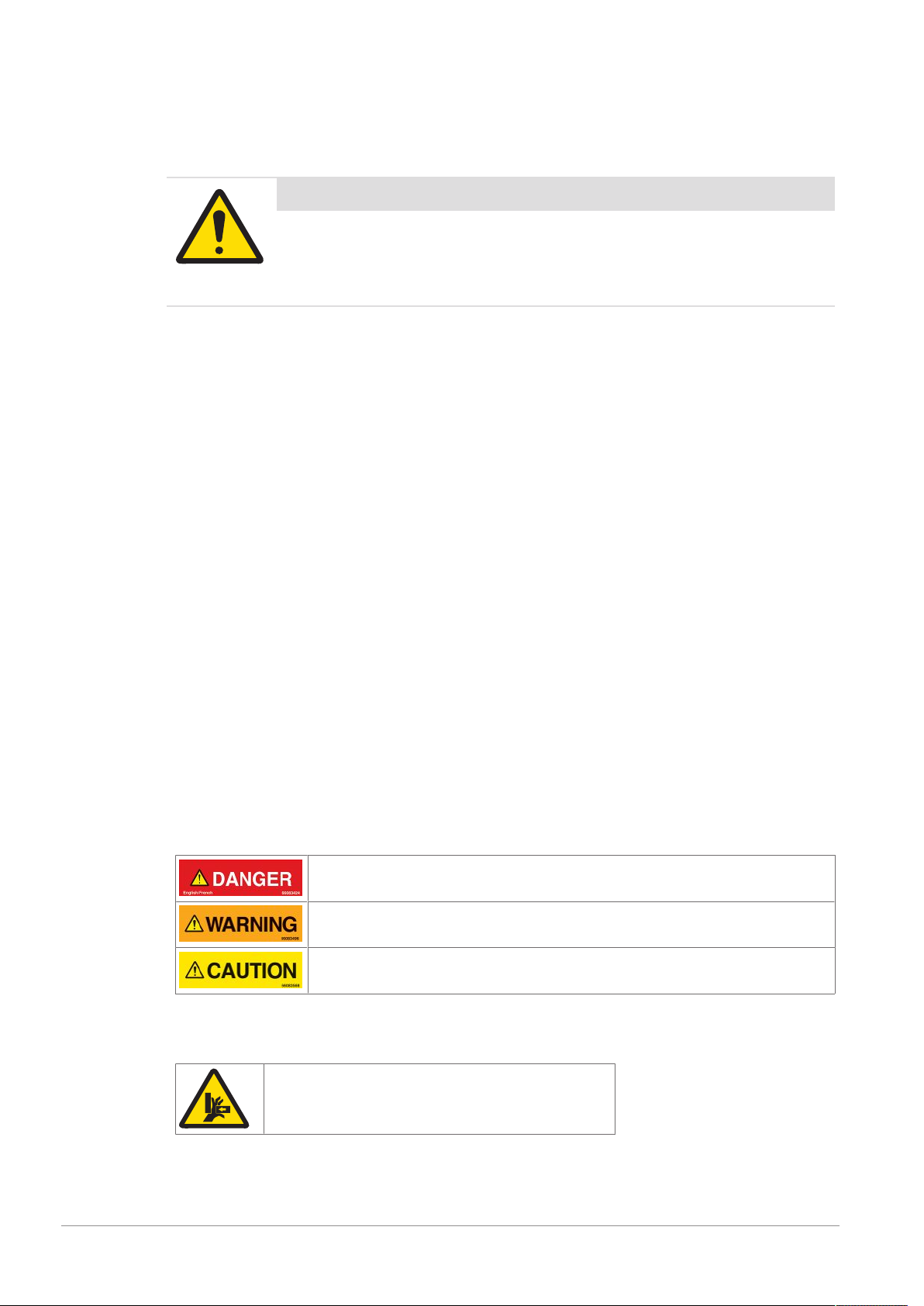
2.1.1.1 Definitions of Signal Words
Signal words describe the level of risk of a particular hazard. The color of the safety label background
indicates the risk, as shown in the following table. The definitions of the signal words are based upon the
ISO3864 definitions.
DANGER (red): This signal word indicates an imminently hazardous situation which,
if not avoided, will result in death or serious injury.
WARNING (orange): This signal word indicates a potentially hazardous situation
which, if not avoided, could result in death or serious injury.
CAUTION (yellow): This signal word indicates a potentially hazardous situation
which, if not avoided, could result in minor or moderate injury.
2.1.1.2 Meaning of Hazard Alert Symbols
The following hazard alert symbols may be installed on your equipment.
Crushing
6 / 34 T2650 Case Aggregation 3.2 - User Manual - Document Version A
Page 7
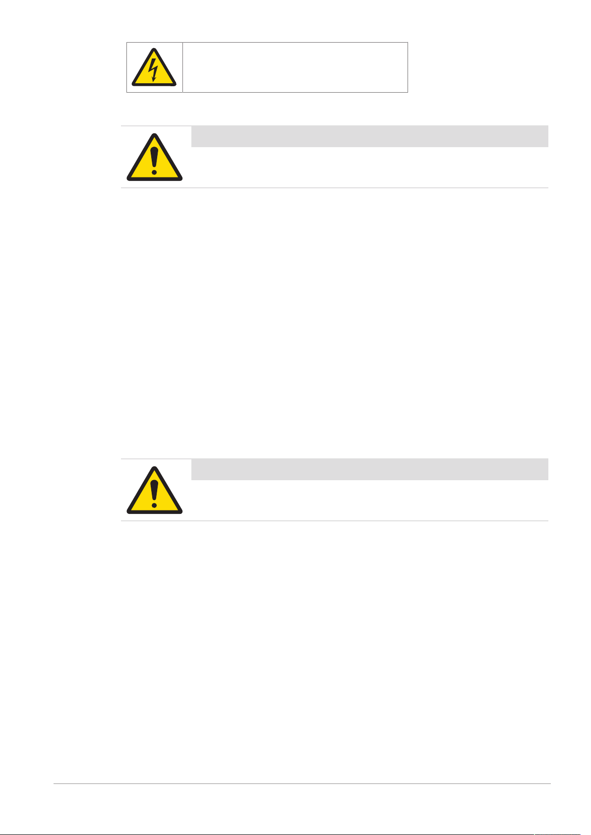
Electrical shock
2.2 General Protective Procedures
Important Safety Message
Make sure that all personnel who work on or near the equipment are capable
of performing all operations in a safe way.
• Keep the manual in a convenient location near the equipment. Replace the manual if it becomes lost or
damaged.
• Wear Personal Protective Equipment (PPE) in accordance with your plant's safety procedures.
• Understand the hazards of the equipment and the risks related to those hazards before working on or
near the equipment.
• Obey all safety procedures of the local plant.
• Do not wear loose clothing, jewelry, long hair, or anything that can become entangled with the
equipment.
• Be careful around the equipment to avoid hitting your head, arms, or other body parts against the
equipment. Be careful if the equipment is over your head.
• Be careful not to trip over cables or other parts of the equipment.
• Do not move quickly in the area around the equipment.
• Do not climb, hang onto, or use any of the part of the equipment as a support.
• Obey the lockout tagout (LOTO) procedures of the plant.
• If there is a safety-related malfunction when you are operating the equipment, press the emergency stop
device. Tell the responsible supervisor, and follow the applicable steps approved by your company to fix
the malfunction.
2.3 Safety Information for Various Activities
Important Safety Message
Read and understand all parts of the manual before using or working on any
equipment.
The following sections list safety information for particular activities or groups of activities. Refer to the
correct sections in the manual for more detailed instructions.
2.3.1 Transporting and Moving the Equipment
• Only transport or move the equipment if you have the applicable training as defined by your company.
• Your company has sole responsibility for the safe moving and transporting of the equipment.
• Use safe moving procedures during transporting to maintain stability and to prevent the equipment from
tipping or falling.
• Disconnect the electrical supply, the pneumatic supply, and the communication cables before you move
the equipment.
• Use the correct lifting devices. If you use a forklift, lift the equipment at the correct lift points as shown by
the blue lift point labels.
• Blue lift point labels are placed on the equipment to show recommended locations for lifting. These lift
point locations were tested with the manufacturer's forklift trucks. A qualified rigger must make sure that
the lift points are correct for your lifting equipment.
• When you lift the equipment by hand, obey the safe lifting procedures of your company.
T2650 Case Aggregation 3.2 - User Manual - Document Version A 7 / 34
Page 8

2.3.2 Installing
Only install the equipment if you have the applicable training as defined by your company.
2.3.3 Operating the Equipment and Monitoring the Inspection Process
• Before beginning operation, make sure that the area is safe.
• Know the location and effect of each emergency stop button that controls the equipment.
• Do not operate the equipment without protective guards and doors in place.
• Do not reach into path of the products when any conveyors are in motion.
• Do not reach into the area around any sorting device, when the equipment is turned on.
• Make sure the safety circuit is working correctly.
• Do regular inspections of the equipment.
• If there is a fault or change in the equipment behavior, stop the equipment and inform responsible
personnel.
2.3.4 Testing and Verifying the Equipment
Only do testing and verifying of the equipment if you have applicable training as defined by your company.
2.3.5 Maintaining, Cleaning and Sanitizing the Equipment
• Remove all power from the equipment before doing any work.
• Keep the equipment in good working order.
• Follow a preventative maintenance program.
• Replace parts when needed.
• Obey the lockout tagout (LOTO) procedures of the plant.
• Test (validate) the safety circuit after parts are replaced.
• Only use METTLER TOLEDO approved spare parts and accessories.
• Do not make any unauthorized modifications to the equipment.
• Replace safety labels if damaged, missing, or unreadable.
• Do a visual check of the equipment at least once during a shift to identify any visual damage or faults.
Report any equipment changes to the responsible supervisor immediately.
• When required for a hygienic production environment, do regular sanitizing of the equipment according
to your company's procedures.
• After cleaning or sanitizing, check all cables, connectors, and pneumatic hoses for leakage, loose
connections, rub marks and damage. Tighten, repair, or replace any faulty cables and air tubing, as
necessary.
2.4 Special Hazards
The following sections describe special instructions for equipment that may have special hazards.
2.4.1 Electricity
• Only work on the electrical systems if you have the applicable electrical training as defined by your
company.
• Keep all electrical enclosure doors closed. If the doors have locks on them, keep them locked.
• Remove all power from the equipment before doing any work.
2.4.2 Moving Parts
• Product inspection equipment moves automatically, intermittently and without notice. Some surfaces
may get hot. Do not place hands or any other body parts on or near the moving parts.
The following are examples of moving parts:
– Conveyor belts and rollers
– Rejectors and product diverters
– Motors
8 / 34 T2650 Case Aggregation 3.2 - User Manual - Document Version A
Page 9

– Gearboxes
– Side grips
– Automatic position adjusters
– Encoders
– Pneumatic cylinder
– Solenoids
• Only operate the equipment with all safeguards in place.
• Make sure that all safeguards are in correct operating condition.
• Do not climb, sit, stand, walk, or ride on the conveyor.
2.4.3 Strobe Lights
• Strobe lights can cause seizures in individuals with photosensitive epilepsy.
• Individuals with photosensitive epilepsy must not operate the equipment.
• Do not operate the equipment when excessively fatigued or after consuming alcohol.
• Do not look directly at the lights, especially at close distances.
• Avoid placing the equipment in areas with reduced lighting.
• If lights are inside of an enclosure, do not open the enclosure doors when lights are flashing.
2.4.4 Lights and Laser Sensors
• Do not stare directly at any lights or lasers.
• Avoid prolonged exposure to ultraviolet (UV) light, infrared (IR) light, and lasers.
T2650 Case Aggregation 3.2 - User Manual - Document Version A 9 / 34
Page 10
3 System Description
3.1 Overview of the T2650 Case Aggregation
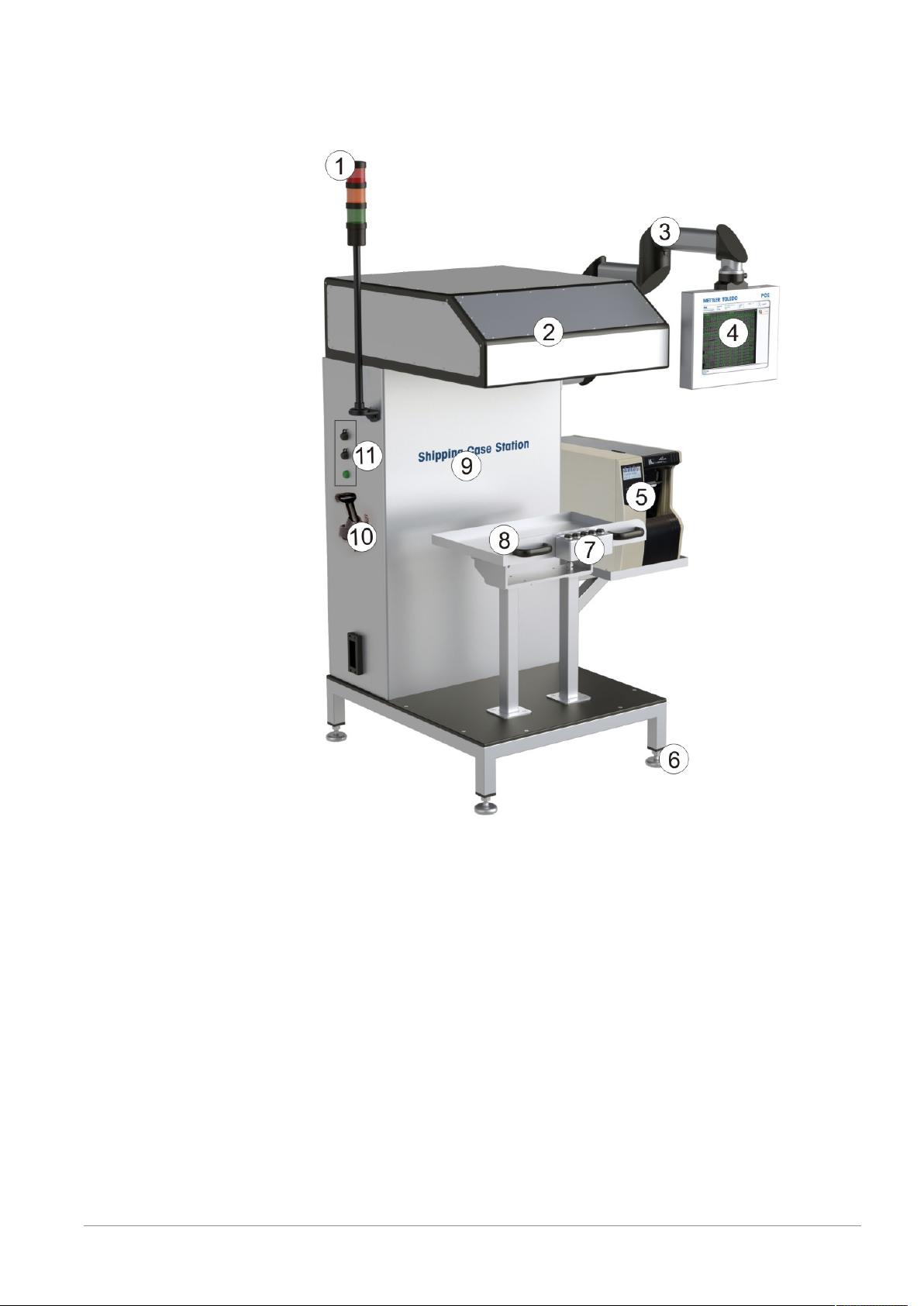
Model T2650 Bottom/Up
1 Stack light
2 Swivel arm
3 Touchscreen
4 Printer
5 Vertical adjustment for the entire system
6 Camera with positioning unit
7 Control unit with buttons: "Start/stop", "Confirm", "Picture reset", "Case Full"
8 Table with glass window
9 USB ports, Ethernet port and UPS LED
10 Hand scanner
- Foot pedal
10 / 34 T2650 Case Aggregation 3.2 - User Manual - Document Version A
Page 11
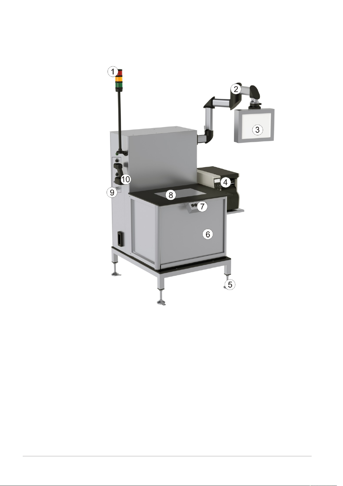
Model T2650 Top/Down
1 Stack light
2 Camera with positioning unit
3 Swivel arm
4 Touchscreen
5 Printer
6 Vertical adjustment for the entire system
7 Control unit with buttons: "Start/stop", "Confirm", "Picture reset", "Case Full"
8 Tilting table
9 Control cabinet
10 Hand scanner
11 USB ports, Ethernet port and UPS LED
- Foot pedal
T2650 Case Aggregation 3.2 - User Manual - Document Version A 11 / 34
Page 12

3.2 Technical Data
Technical Details
Technical Details Shipping Case Station
Measures (HxWxD) in mm 2095 x1400 x1128
Control cabinet (HxWxD) in mm 1200 x 800 x 300
Power supply 115/230V VAC 50/60 Hz, Single Phase, 800 VA
Interfaces Serial (COM1, COM2 [and COM3]), RS232C, USB
(expandable via hub), Ethernet (RJ45)100/1000
MBit/s
System power consumption Approx. 800 VA
3.3 Dependencies
In order for the machine to run correctly and to use the full functionality you need to have the following
versions installed:
• PLM 4.17 or latest version
• HRC 3.12 or latest version
• VRC 2.0.0.0
12 / 34 T2650 Case Aggregation 3.2 - User Manual - Document Version A
Page 13

13 / 34 T2650 Case Aggregation 3.2 - User Manual - Document Version A
3.4 Workflow
Page 14

4 Components
The T2650 contains the following components
• Central operation via HMI (PLM optional)
• High-resolution camera, typically 11 megapixels
• High-performance LED lighting (maintenance-free)
• Evaluation processor (Windows-based)
• UPS
• Central main switch; 24 DC power supply unit
• Electronically adjustable camera lens
• Monitor for visualization purposes
• Signal lamp
• Foot pedal
4.1 Operational Area
The verification of all items is performed by the High Resolution Camera. The data matrix codes are
collected automatically and aggregated by the PLM.
4.2 Brief Description
The PCE Shipping Case Station is a complete solution and can therefore easily be used as a "standalone"
unit for manual packaging. The system includes software for managing and controlling the installed
equipment, as well as for analysing the data determined by the PCE High Resolution Camera.
T2650 Top/Down:
Manually place the box beneath the camera and trigger the reading with the foot pedal or by tilting the table.
The PLM verifies the subsequently determined data.
T2650 Bottom/Up
Manually place the folding box(es) on top of the glass window and trigger the reading with the foot pedal.
The PLM verifies the subsequently determined data.
Code Reading
The Shipping Case Station automatically verifies all 1D codes (eg. code 39, 93, 128) or 2D codes
(Datamatrix, QR-Code) with a single shot. A label is generated based on the information gathered. The socalled "parent-child" connection is therefore reproduced quickly and reliably.
Stack Light Color Meaning
Color Meaning
Green System running
Yellow
Red System stopped
Calibration of the position of the camera after turning on the T2650.
14 / 34 T2650 Case Aggregation 3.2 - User Manual - Document Version A
Page 15

5 Installation
The PLM is installed on the T2650 Case Aggregation before delivery.
§
1 Connect the T2650 to the power supply. The input voltage should be between 115 and 230 VAC.
2 Adapt the PLM according to the desired formats.
3 Take the necessary steps detailed in the PLM user manual.
T2650 Case Aggregation 3.2 - User Manual - Document Version A 15 / 34
Page 16

6 Device Settings at Line Format
6.1 PLC
For the PLC there are no predefined device formats to load. This chapter describes the settings and
parameter of the PLC in the line format.
NOTICE
Dropdown Lists not yet Supported
Do not use the dropdown lists in the PLC device format as they are not yet supported.
1. Select Production > Add/Edit line format > <select line format from list> Devices.
2. Select the PLC tab.
3. Activate the option Activated.
4. Press Add.
5. Type the name of the device format into the field Name:.
6. Press Save.
The parameter fields appear.
7. Edit the settings of the PLC and press Save.
Which parameter fields appear at the PLC tab is depending on the system settings of the PLC.
T2650 Top/Down
Figure: Production > Add/Edit line format > Devices > (PLC tab)
Frequently used parameters are:
16 / 34 T2650 Case Aggregation 3.2 - User Manual - Document Version A
Page 17

Name Description
AutoCaseFull If the parameter is set to 'true' and the expected amount of good layers is reached,
the PLC automatically generates the case full message. If the parameter is not active,
you have to press the case full button on the machine manually.
AutoReset If the parameter is set to 'true' and the expected counts of codes per layer is not
found by the camera, you have to press Confirm. This confirmation will automatically confirm the PLM message, reset the picture and re-trigger the camera for a new
picture. Instead of pressing one of the confirm buttons, you could also press the foot
pedal.
Layer The number of layers inside a case.
LayerHeight Height of the layers in millimeter.
OneHeightMode If the parameter is set to 'true, the camera changes position according to the layer
height for the first reading. The different layers of the case are not stockpiled. Instead,
each layer is placed on the table, a picture is taken, and the layer is packed into the
case. Throughout production the camera is kept on the initial layer height.
TableHeight Enter the number the display of the table crank shows, in millimeters without decimal
places.
T2650 Bottom/Up
Figure: Production > Add/Edit line format > Devices > (PLC tab)
Frequently used parameters are:
Name Description
AutoCaseFull If the parameter is set to 'true' and the expected amount of good layers is reached,
the PLC automatically generates the case full message. If the parameter is not active,
you have to press the case full button on the machine manually.
T2650 Case Aggregation 3.2 - User Manual - Document Version A 17 / 34
Page 18

Name Description
AutoReset If the parameter is set to 'true' and the expected counts of codes per layer is not
found by the camera, you have to press Confirm. This confirmation will automatically confirm the PLM message, reset the picture and re-trigger the camera for a new
picture. Instead of pressing one of the confirm buttons, you could also press the foot
pedal.
Layer The number of layers inside a case.
6.2 HRC
The parameters available depend on the selected pre-configured format. This chapter describes the settings
and parameters of the HRC in the line format.
1. Select Production > Add/Edit line format > <select line format from list> Devices.
2. Select the HRC tab.
3. Activate the option Activated.
4. Press Add.
5. Type the name of the device format into the field Name:.
6. Press Save.
The parameter fields appear.
7. Edit the settings of the HRC and press Save.
Figure: Production > Add/Edit line format > Devices > (HRC tab)
Frequently used parameters are:
Name Description
ChildRank The rank in which the items that have to be aggregated were aggregated before
scanning.
18 / 34 T2650 Case Aggregation 3.2 - User Manual - Document Version A
Page 19

Name Description
ContentSize Number of items contained in whole case.
Select the AI 37 from the dropdown list to get the value from the reader on rank > 1
during production and leave the input field empty.
Do not select an AI but type a value in the input field if you want to use a fix value.
OffsetRank The number of the rank where the labels that have to be scanned come from.
layerSize Number of items contained in one layer.
Select the AI R36 from the dropdown list to get the value from the reader on rank > 1
during production and leave the input field empty. You have to select the AI if you
want to aggregate partial units as well.
Do not select an AI but type a value in the input field if you want to use a fix value.
NOTICE
Partial Unit
The AI R36 (layer size) on the rank of partial unit is required. For further information see
PLM user manual, chapter "PCE_PARTIAL_UNIT module".
NOTICE
One Layer Only
If the case has only one layer, layer size and content size must have the same value.
For further information see PLM user manual, chapter "Device Settings at Line Format - High Resolution
Camera".
Further Information on Aggregation
For further information see PLM user manual, chapter "Aggregation".
T2650 Case Aggregation 3.2 - User Manual - Document Version A 19 / 34
Page 20

7 Handling
7.1 T2650 Top/Down
Single-Layer Case
Precondition: PLM is installed, settings are correct and full functionality of the system is given.
§
1 Turn on the main switch. The PCE Line Manager software (PLM) and the High Resolution Camera
software (HRC-AI Software) will start up automatically.
2 Log-in to the PLM, select the desired line format and start an order. (The specific procedure is detailed in
the PLM user manual.) The Home view is displayed.
3 Select the "HRC" to show the results of the camera reading on the monitor.
4 Place a case with the individual products on the tilting table below the High Resolution Camera.
5 Press the foot pedal or move the tilting table to the acquisition position (horizontal) to start the image
acquisition. The results will be shown on the monitor (with green borders for “good” codes and red
borders for “bad” codes).
6 Replace “bad” products, if necessary, and start the image acquisition again using the foot pedal.
ð When all codes are read as “good”, the label printer will print automatically. This label can be
checked by using the handheld scanner (optional) or a Smart Camera (optional), if required. Stick
the label onto the case.
ð The item to case aggregation is completed.
Multi-Layer Case
The operation for multi-layer cases is almost the same as for single-layer cases, apart from the following
changes:
• If a processing result of a layer contains "bad" products, press the "picture reset" button. Replace all
"bad" products and start a new image acquisition using the foot pedal or by moving the tilting table to
the acquisition position. If "bad" products still remain, repeat the previous step until all products are read
as “good”.
• If the top layer contains completely “good” products, press the “case full“ button. The printer will then
print the label for the case.
20 / 34 T2650 Case Aggregation 3.2 - User Manual - Document Version A
Page 21

NOTICE
Behavior is configurable
Depending on the PLC settings at the line format, the T2650 might behave differently. See
also chapter [PLC}Page16].
7.2 T2650 Bottom/Up
Multi-Item Case
Precondition: PLM is installed, settings are correct and full functionality of the system is given.
§
1 Turn on the main switch. The PCE Line Manager software (PLM) and the High Resolution Camera
software (HRC-AI Software) will start up automatically.
2 Log-in to the PLM, select the desired line format and start an order. (The specific procedure is detailed in
the PLM user manual.) The Home view is displayed.
3 Select the "HRC" to show the results of the camera reading on the monitor.
4 Place all items (folding boxes or bundles) on the table.
5 Press the foot switch to start the image acquisition. The results will be shown on the monitor (with green
borders for “good” codes and red borders for “bad” codes).
6 Replace “bad” products, if necessary, and start the image acquisition again using the foot switch.
ð When all codes are read as “good”, the label printer will print automatically. This label can be
checked by using the handheld scanner (optional) or a Smart Camera (optional), if required. Stick
the label onto the case.
ð The item/bundle to case aggregation is completed.
NOTICE
Behavior is configurable
Depending on the PLC settings at the line format, the T2650 might behave differently. See
also chapter [PLC}Page16].
7.3 Further Information
The following manuals are also necessary for operation of the T2650:
• PLM (PCE Line Manager)
• HRC - AI (High Resolution Camera - Aggregation Inspection)
Printer
For Maintenance, Refill and Troubleshooting and all other tasks concerning the printer, refer to
printer manual.
7.4 System Shutdown
Make sure the order is suspended or finished before switching off the power.
Switching of while an order is running may cause a loss of production data.
To shut down the system, perform the following task.
T2650 Case Aggregation 3.2 - User Manual - Document Version A 21 / 34
Page 22

− Switch off the power switch
Main Switch
ð System will shut down properly thanks to the uninterruptible power supply.
22 / 34 T2650 Case Aggregation 3.2 - User Manual - Document Version A
Page 23

8 Troubleshooting
8.1 System Behavior After Loss of Power
When power to the system is restored, the system will automatically restart.
The operating procedure corresponds to the procedure used after the main power switch has been turned
on.
8.2 Contact Technical Service
If you encounter persistent problems and would like to call Technical Service or the service hotline, please
be ready to provide as much information as possible:
• Type (model)
• Serial number
• Year of manufacture
• PCE order number and order date (if known)
• Software version displayed on the terminal
• Wording of the error message displayed or a precise description of the problem this enables us to help
you more efficiently.
8.3 Alarm Messages
Plain-text alarm messages appear at the terminal in the info field of the basic display and provide information about particular processes or malfunctions. For information about the alarm messages refer to the
Alarm List. For some alarms you can find more detailed information in the appendix of the PLM user
manual, in the chapter "Troubleshooting Guide".
T2650 Case Aggregation 3.2 - User Manual - Document Version A 23 / 34
Page 24

9 Cleaning and Maintenance
9.1 Visual Inspection and Cleaning of the System
Interval What?
Daily General visual inspection
As needed
• Clean the system and terminal using soft cloths dampened with a mild solution of soap and water or a
commercially available glass and plastic cleaner.
Cleaning of the glass table (T2650 Bottom/Up) or
the glass (T2650 Top/Down)
WARNING
Cleaning the system when it is hot may cause severe damage.
Only clean the system with liquid when it is cooled down to room temperature.
WARNING
Careless cleaning may cause severe damage.
Never use a high pressure jet to hose down the system.
Do not use caustic cleaning agents containing solvents to clean the system and the
terminal. Never use pure alcohol or concentrated acid or lye.
Use particular care when cleaning in order to avoid damage and, above all, to prevent
water from entering the system.
9.2 Visual inspection of Gaskets/Seals
Recommended inspection
interval
Monthly Perform a general visual inspection.
What needs to be done?
if necessary, clean the light barriers.
9.3 Spare Parts and Warranty
CAUTION
For safety and warranty reasons, only Technical Service or technical
personnel authorized by PCE are permitted to replace a motor or the terminal.
If you would like to perform these maintenance tasks yourself, please contact our service
hotline for information about the required training for your personnel.
Keep spare parts on hand
Keeping spare parts on hand – especially for wear parts – can help reduce downtime. Please
contact us if you have any questions.
9.4 General Advice on Stainless Steel Maintenance
Stainless steel generally provides much better protection against corrosion when compared with steel or
aluminium. Stainless steel, however, does not always remain rust-free. Stainless steel can also become
dirty or rusty to some extent, depending on the operational use and the conditions in the working
environment. The most common causes are surface rust (fine iron particles in the air), active gases, the
accumulation of sediments and the build-up of salts. These superficial damages can be easily removed by
using a stainless steel spray daily. After cleaning with soap and water, you should check that the residue is
washed off with a suitable amount of water.
24 / 34 T2650 Case Aggregation 3.2 - User Manual - Document Version A
Page 25

9.5 Cleaning the Touch Screen
The display surface is made from glass and the casing from stainless steel. To ensure efficient operation,
the surface of the touch screen should be cleaned regularly. Only special cleaning wipes and cleaning
agents should be used:
• Commercial cleaners for computer equipment
• Alcohol-based disinfectants
CAUTION
Solvents can damage the display.
Never use diluting agents, benzene, abrasives or other strong solvents, as these can
damage the display!
T2650 Case Aggregation 3.2 - User Manual - Document Version A 25 / 34
Page 26

10 Transport and Storage
10.1 Transporting the System
CAUTION
Risk of injury and damage to property
When the system is transported using a lift truck or other similar vehicle, its upper section
should be held in place by one additional person (or two additional persons, if
necessary) to prevent the system from tipping over.
The weight of the system is considerable, and its center of gravity varies depending on the specific structural
design desired by the customer. It is therefore difficult to provide recommendations for specific lifting points.
You can find more detailed (i.e. order-specific) information on the center of gravity in the accompanying
documents.
10.2 Preparing for Transport
• Shut off the system and have it disconnected from the power supply by a qualified electrician.
CAUTION
The system must never be subjected to major mechanical stresses (impacts,
etc.). Impacts – regardless of the direction from which they act on the system
– or falls can destroy the system.
Make sure that any protruding parts such as light barrier holders, etc. do not become bent
and do not injure anyone.
Take particular care to protect plastic covers.
10.3 Storing the System, Accessories and Spare Parts
• Store the system upright in the original packaging in a clean and dry place until it is to be installed.
• Keep all electronic parts delivered in antistatic bags in their bags until the parts are to be used. This
ensures that they are optimally protected.
26 / 34 T2650 Case Aggregation 3.2 - User Manual - Document Version A
Page 27

11 Interfaces
11.1 Overview of the Interfaces
All interfaces are located on the IPC unit of the system. The unit is mounted inside the cabinet (depending
on the design).
IPC Overview
a Power connector (24V AC-IN or phoenix plug)
b DVI port
c Display port
d RS232 port (COM1)
e 2 x Ethernet
f 4x USB 3.0
11.1.1 Ethernet
Ethernet port
Ethernet is a computer networking technology for local networks. The ethernet interface is a pluggable
connection. A connection (link) is indicated by a steady yellow LED (on right side of connector) and data
transmission (active) is indicated by a green LED (on left side of connector, flashes during data transfer).
11.1.2 USB
Interfaces are for internal use only
All interfaces are for internal use only and cannot not be used by operators.
USB port
T2650 Case Aggregation 3.2 - User Manual - Document Version A 27 / 34
Page 28

USB is a serial I/O interface. The USB ports comply with the USB 2.0 specification and are located on the
IPC and on the outside of the control cabinet.
If you require more USB ports, then a USB hub can be used to expand one of the ports and to provide
additional connections. PCE is responsible for the technical design of the hub.
11.1.3 Keyboard Connection
USB port
It is possible to connect a standard external keyboard to the System via USB port.
11.1.4 Serial Ports (COM1, COM2 and COM3)
Serial port
Depending on the IPC variant, the terminal has two or three serial ports: COM1, COM2, COM3, COM4).
Possible interface type: V24/RS232C interface, with or without handshake lines, with a maximum transmission distance of 10 m.
28 / 34 T2650 Case Aggregation 3.2 - User Manual - Document Version A
Page 29

12 Further Information
Inside the control cabinet of your equipment, you find the following further documentation:
• CE Certificate of Conformity
• Wiring diagram
T2650 Case Aggregation 3.2 - User Manual - Document Version A 29 / 34
Page 30

13 Disposal
In conformance with the European Directive 2012/19/EU on Waste Electrical and
Electronic Equipment (WEEE) this device may not be disposed of in domestic waste. This
also applies to countries outside the EU, per their specific requirements.
Please dispose of this product in accordance with local regulations at the collecting point
specified for electrical and electronic equipment. If you have any questions, please contact
the responsible authority or the distributor from which you purchased this device. Should
this device be passed on to other parties, the content of this regulation must also be
related.
30 / 34 T2650 Case Aggregation 3.2 - User Manual - Document Version A
Page 31

Glossary
Case
A case is a packaging unit at the aggregation process.
It consists of several items or bundles. It is usually
aggregated to a pallet.
COM
Serial interfaces for bidirectional data transfer between
the PC and peripheral devices.
DVI
Digital Visual Interface
HMI
Human Machine Interface
HRC
High Resolution Camera
HRC-AI
High Resolution Camera - Aggregation Inspection.
High Resolution Camera Software. Software of the HRC
HxWxD
Height x Width x Depth
IPC
Industrial PC
LED
Light-emitting diode
PCE
Pharmacontrol Electronic GmbH
PLC
Programmable logic controller
QR-Code
Quick response code
RS232
Standard for a serial interface
UPS
Uninterruptible power supply
USB
Universal Serial Bus
VA
Volt Ampere
VAC
Volt Alternating Current
T2650 Case Aggregation 3.2 - User Manual - Document Version A 31 / 34
Page 32

Intentionally left blank
32 / 34 T2650 Case Aggregation 3.2 - User Manual - Document Version A
Page 33

Page 34

Pharmacontrol Electronic GmbH
Harzstraße 1
64646 Heppenheim, Germany
Tel. +49 6252 6736 0
Fax +49 6252 6736 111
www.mt.com
Subject to technical changes.
© Pharmacontrol Electronic GmbH 05/2018
T2650 Case Aggregation 3.2 - User Manual - Document Version A
www.mt.com/pce
For more information
 Loading...