

Page 1

User Manual
T2611 - Manual Serialization
Document Version E
Page 2

Intentionally left blank
2 / 40 T2611 - Manual Serialization - User Manual - Document Version E
Page 3

Table of Contents
1 Introduction 5
1.1 Intended Audience........................................................................................................ 5
1.2 Intended Use and Foreseeable Misuse ............................................................................ 5
1.3 Original Language ....................................................................................................... 5
1.4 Contacting METTLER TOLEDO Service............................................................................. 5
1.5 Additional Documents .................................................................................................. 6
2 Safety Notes 7
2.1 Safety Labels and Notice Labels .................................................................................... 7
2.2 General Protective Procedures ....................................................................................... 8
2.3 Safety Information for Various Activities........................................................................... 8
2.4 Special Hazards .......................................................................................................... 9
2.1.1 Hazard Notifications ...................................................................................... 7
2.1.1.1 Definitions of Signal Words ...................................................................... 7
2.1.1.2 Meaning of Hazard Alert Symbols.............................................................. 7
2.1.2 Mandatory Procedures................................................................................... 7
2.3.1 Transporting and Moving the Equipment .......................................................... 8
2.3.2 Installing...................................................................................................... 9
2.3.3 Operating the Equipment and Monitoring the Inspection Process......................... 9
2.3.4 Testing and Verifying the Equipment ................................................................ 9
2.3.5 Maintaining, Cleaning and Sanitizing the Equipment ......................................... 9
2.4.1 Electricity ..................................................................................................... 9
2.4.2 Strobe Lights ................................................................................................ 9
3 Equipment Overview 10
3.1 Equipment Function ..................................................................................................... 10
3.2 Equipment Description.................................................................................................. 11
4 Transporting, Moving, and Storage 13
4.1 Transporting the Equipment........................................................................................... 13
4.2 Storing the Equipment .................................................................................................. 14
4.3 Unpacking the Equipment ............................................................................................. 14
5 Installation 15
5.1 Mechanical and Electrical Installation............................................................................. 15
5.2 Setting up the Equipment .............................................................................................. 15
5.2.1 Set up the hand scanner ................................................................................ 15
5.2.2 Set up the Smart Camera ............................................................................... 16
5.2.2.1 Setting up a Product in SMC ..................................................................... 17
5.2.2.2 Final Result for SMC setup........................................................................ 25
5.2.3 Set up the printer........................................................................................... 26
6 Operation 27
6.1 Starting the Equipment.................................................................................................. 27
6.2 Setting the Box Size...................................................................................................... 27
6.3 Workflow .................................................................................................................... 28
6.3.1 Workflow 1: Print - Verify - Commission .......................................................... 28
6.3.2 Workflow 2: Decommission ........................................................................... 31
6.4 Shutting down the Equipment........................................................................................ 32
7 Maintenance 33
7.1 Changing the Printer Cartridge....................................................................................... 33
8 Cleaning 35
8.1 Visual Inspection and Cleaning of the System.................................................................. 35
8.2 Visual inspection of Gaskets/Seals ................................................................................. 35
8.3 Cleaning the Touch Screen............................................................................................ 35
8.4 Cleaning the Print Head................................................................................................ 35
8.5 General Advice on Stainless Steel Maintenance................................................................ 36
T2611 - Manual Serialization - User Manual - Document Version E 3 / 40
Page 4

9 Disposal 37
10 Technical Data SMC Series 3 38
4 / 40 T2611 - Manual Serialization - User Manual - Document Version E
Page 5

1 Introduction
1.1 Intended Audience
This manual is written for non-technical personnel. For the purpose of this manual, non-technical personnel
are those who do not have specialized knowledge and training in the installation, commissioning,
integration, validation, or major maintenance of the equipment.
This manual gives basic information for the following activities:
• Transporting and setting the equipment in place
• Setting up a product and changing a product
• Operating the equipment
• Maintaining and cleaning the equipment
1.2 Intended Use and Foreseeable Misuse
In this manual, the METTLER TOLEDO vision solution, including all of its components, is referred to as the
"equipment".
The equipment must only be used for the visual inspection of products, according to the procedures in this
manual. Any other use of the equipment is considered misuse.
Common foreseeable misuses include the following:
• Replacing or modifying parts without approval from METTLER TOLEDO
• Operating the equipment beyond the limits of the technical specifications
• Not obeying the instructions and safety notes described in this manual
• Using the equipment in a hazardous environment
1.3 Original Language
The original manual is written in English. If you are reading a translated version of this manual, and you
also need the English original manual, you can ask METTLER TOLEDO to supply it. If you have a question
about the intended meaning of any translated text, consult the original English-language manual.
1.4 Contacting METTLER TOLEDO Service
Contact your authorized METTLER TOLEDO Service representative about the following products and services:
• Installation
• Integration
• Start-up support
• Commissioning
• Performance verification and audit services to certify that your equipment is maintaining its performance
levels
• Certified, genuine parts
• Emergency repairs and support
• Service contracts customized to your needs
• Customer training
For more information, contact your local and authorized METTLER TOLEDO Service representative using the
link below (and, if necessary, select the applicable country):
http://www.mt.com/contact
When you contact the Service Department, have the following information available, if applicable:
• METTLER TOLEDO order number and date
• Equipment name, model, or type
• Serial number
• Production line name
• Software version
• Precise wording of the displayed error message or detailed fault description
• Pictures or videos of the part or problem
T2611 - Manual Serialization - User Manual - Document Version E 5 / 40
Page 6

1.5 Additional Documents
For details on the individual components of the T2611 Manual Serialization refer to the respective User
Manual:
• User Manual PLM or User Manual PLM direct
• Hardware User Manual Smart Camera (SMC)
• Software User Manual SMC Optical Character / Code Verification
• User Manual on printer (for example Bluhm Weber or Wolke printer)
The following additional documentation is included with your equipment:
• CE Certificate of Conformity (when applicable)
• Wiring diagrams and engineering drawings
6 / 40 T2611 - Manual Serialization - User Manual - Document Version E
Page 7
2 Safety Notes
Important Safety Message
Read and understand all the safety information in the following sections as
well as the safety messages in the rest of this manual.
If you do not follow the safety information and messages, this may lead to property
damage and personal injury up to and including death.
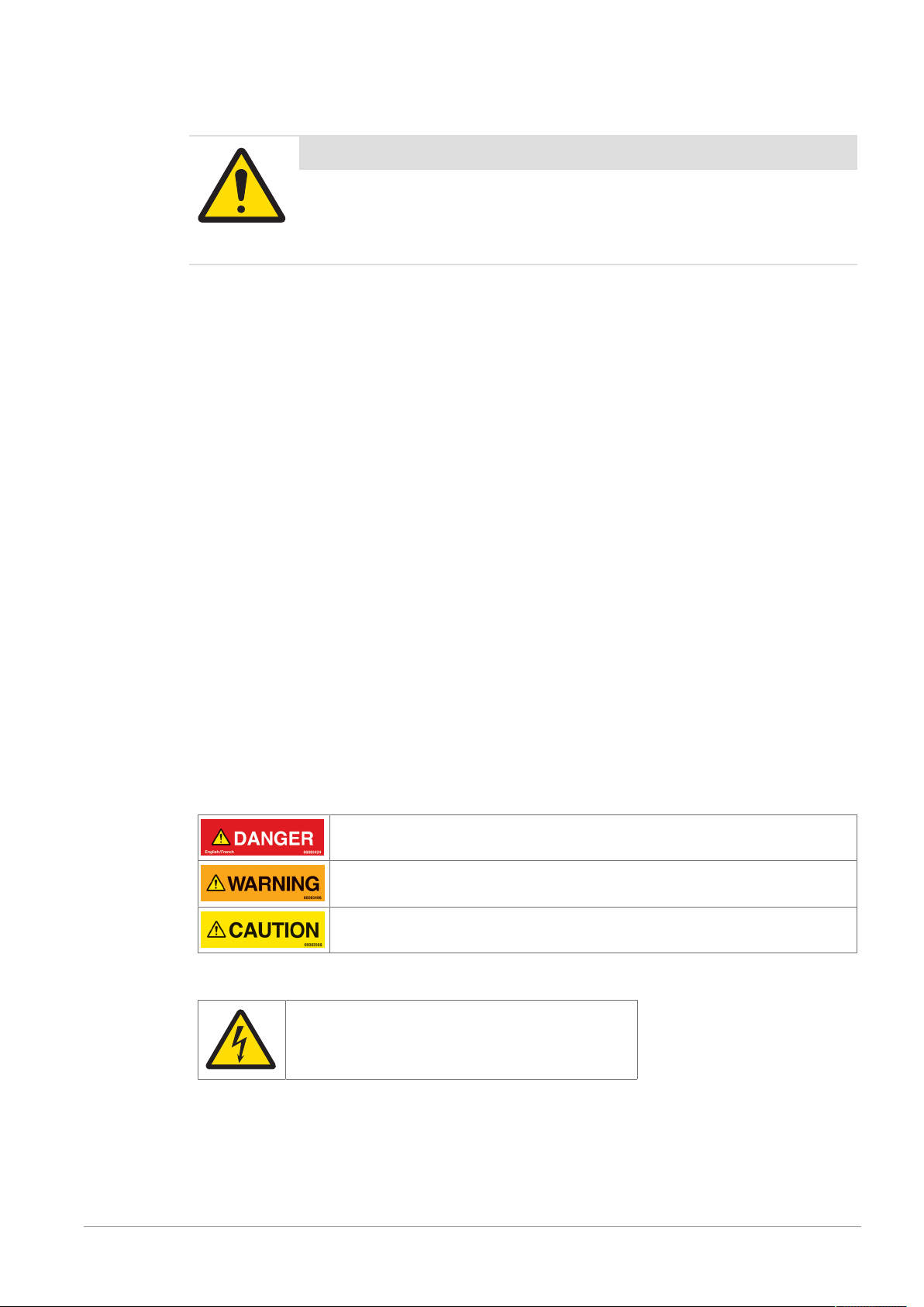
2.1 Safety Labels and Notice Labels
The ISO3864 safety labels are installed at potentially hazardous areas on the equipment. They give special
safety-related notifications. The locations of these labels are given in the drawings supplied with your
equipment. There are three types of safety labels:
• Hazard notifications
• Mandatory procedures
• Prohibitive procedures
Additionally, NOTICE labels may appear on your equipment.
The meanings of the different kinds of labels are explained in the following sections.
Before you transport, install, operate or work on the equipment, find out about the location and meanings of
the labels. Maintain the labels so that they are clear of obstructions and are readable. Do not remove any
labels. Replace any label that is no longer readable.
2.1.1 Hazard Notifications
A hazard notification consists of the following:
• Hazard alert symbol (yellow triangle with black symbol)
• Signal word (DANGER , WARNING , or CAUTION )
• Special notifications related to the hazard (as required)
The signal word labels are attached next to the hazard alert symbol labels on the equipment.
2.1.1.1 Definitions of Signal Words
Signal words describe the level of risk of a particular hazard. The color of the safety label background
indicates the risk, as shown in the following table. The definitions of the signal words are based upon the
ISO3864 definitions.
DANGER (red): This signal word indicates an imminently hazardous situation which,
if not avoided, will result in death or serious injury.
WARNING (orange): This signal word indicates a potentially hazardous situation
which, if not avoided, could result in death or serious injury.
CAUTION (yellow): This signal word indicates a potentially hazardous situation
which, if not avoided, could result in minor or moderate injury.
2.1.1.2 Meaning of Hazard Alert Symbols
Electrical shock
2.1.2 Mandatory Procedures
Mandatory procedures alert personnel to special, required actions. The round labels have blue backgrounds
and white symbols. The symbols describe the required action. The following table lists the mandatory
procedures labels which may be installed on your equipment.
T2611 - Manual Serialization - User Manual - Document Version E 7 / 40
Page 8
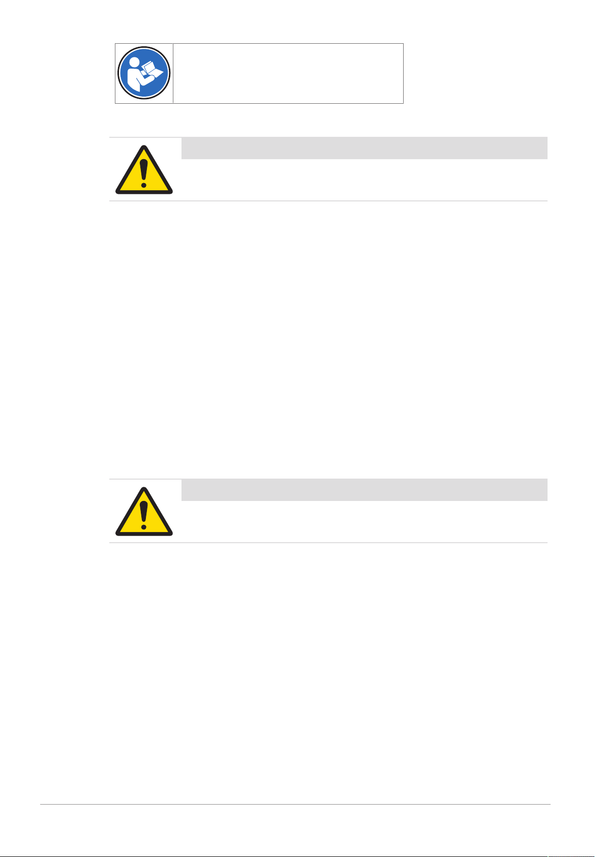
Read the manual
2.2 General Protective Procedures
Important Safety Message
Make sure that all personnel who work on or near the equipment are capable
of performing all operations in a safe way.
• Keep the manual in a convenient location near the equipment. Replace the manual if it becomes lost or
damaged.
• Wear Personal Protective Equipment (PPE) in accordance with your plant's safety procedures.
• Understand the hazards of the equipment and the risks related to those hazards before working on or
near the equipment.
• Obey all safety procedures of the local plant.
• Do not wear loose clothing, jewelry, long hair, or anything that can become entangled with the
equipment.
• Be careful around the equipment to avoid hitting your head, arms, or other body parts against the
equipment. Be careful if the equipment is over your head.
• Be careful not to trip over cables or other parts of the equipment.
• Do not move quickly in the area around the equipment.
• Do not climb, hang onto, or use any of the part of the equipment as a support.
• Obey the lockout tagout (LOTO) procedures of the plant.
• If there is a safety-related malfunction when you are operating the equipment, press the emergency stop
device. Tell the responsible supervisor, and follow the applicable steps approved by your company to fix
the malfunction.
2.3 Safety Information for Various Activities
Important Safety Message
Read and understand all parts of the manual before using or working on any
equipment.
The following sections list safety information for particular activities or groups of activities. Refer to the
correct sections in the manual for more detailed instructions.
2.3.1 Transporting and Moving the Equipment
• Only transport or move the equipment if you have the applicable training as defined by your company.
• Your company has sole responsibility for the safe moving and transporting of the equipment.
• Use safe moving procedures during transporting to maintain stability and to prevent the equipment from
tipping or falling.
• Disconnect the electrical supply, the pneumatic supply, and the communication cables before you move
the equipment.
• Use the correct lifting devices. If you use a forklift, lift the equipment at the correct lift points as shown by
the blue lift point labels.
• Blue lift point labels are placed on the equipment to show recommended locations for lifting. These lift
point locations were tested with the manufacturer's forklift trucks. A qualified rigger must make sure that
the lift points are correct for your lifting equipment.
• When you lift the equipment by hand, obey the safe lifting procedures of your company.
8 / 40 T2611 - Manual Serialization - User Manual - Document Version E
Page 9

2.3.2 Installing
Only install the equipment if you have the applicable training as defined by your company.
2.3.3 Operating the Equipment and Monitoring the Inspection Process
• Before beginning operation, make sure that the area is safe.
• Make sure the safety circuit is working correctly.
• Do regular inspections of the equipment.
• If there is a fault or change in the equipment behavior, stop the equipment and inform responsible
personnel.
2.3.4 Testing and Verifying the Equipment
Only do testing and verifying of the equipment if you have applicable training as defined by your company.
2.3.5 Maintaining, Cleaning and Sanitizing the Equipment
• Remove all power from the equipment before doing any work.
• Keep the equipment in good working order.
• Follow a preventative maintenance program.
• Replace parts when needed.
• Obey the lockout tagout (LOTO) procedures of the plant.
• Test (validate) the safety circuit after parts are replaced.
• Only use METTLER TOLEDO approved spare parts and accessories.
• Do not make any unauthorized modifications to the equipment.
• Replace safety labels if damaged, missing, or unreadable.
• Do a visual check of the equipment at least once during a shift to identify any visual damage or faults.
Report any equipment changes to the responsible supervisor immediately.
• When required for a hygienic production environment, do regular sanitizing of the equipment according
to your company's procedures.
• After cleaning or sanitizing, check all cables, connectors, and pneumatic hoses for leakage, loose
connections, rub marks and damage. Tighten, repair, or replace any faulty cables and air tubing, as
necessary.
2.4 Special Hazards
The following sections describe special instructions for equipment that may have special hazards.
2.4.1 Electricity
• Only work on the electrical systems if you have the applicable electrical training as defined by your
company.
• Keep all electrical enclosure doors closed. If the doors have locks on them, keep them locked.
• Remove all power from the equipment before doing any work.
2.4.2 Strobe Lights
• Strobe lights can cause seizures in individuals with photosensitive epilepsy.
• Individuals with photosensitive epilepsy must not operate the equipment.
• Do not operate the equipment when excessively fatigued or after consuming alcohol.
• Do not look directly at the lights, especially at close distances.
• Avoid placing the equipment in areas with reduced lighting.
• If lights are inside of an enclosure, do not open the enclosure doors when lights are flashing.
T2611 - Manual Serialization - User Manual - Document Version E 9 / 40
Page 10

3 Equipment Overview
3.1 Equipment Function
The T2611 Manual Serialization is a desktop device for small batch serialization. The system contains a
printer for printing a serialized code onto a carton and a Smart Camera to check the Datamatrix Code and
Human Readable Text. The software allows configuration and visualization.
Supported carton sizes:
• Length (L) = 50 ... 360 mm
• Width (W) = 60 ... 190 mm
• Height (H) = 25 ... 220 mm
Smaller heights upon request.
The printer together with the Smart Camera can be moved up and down to allow flexible vertical printing
areas.
10 / 40 T2611 - Manual Serialization - User Manual - Document Version E
Page 11
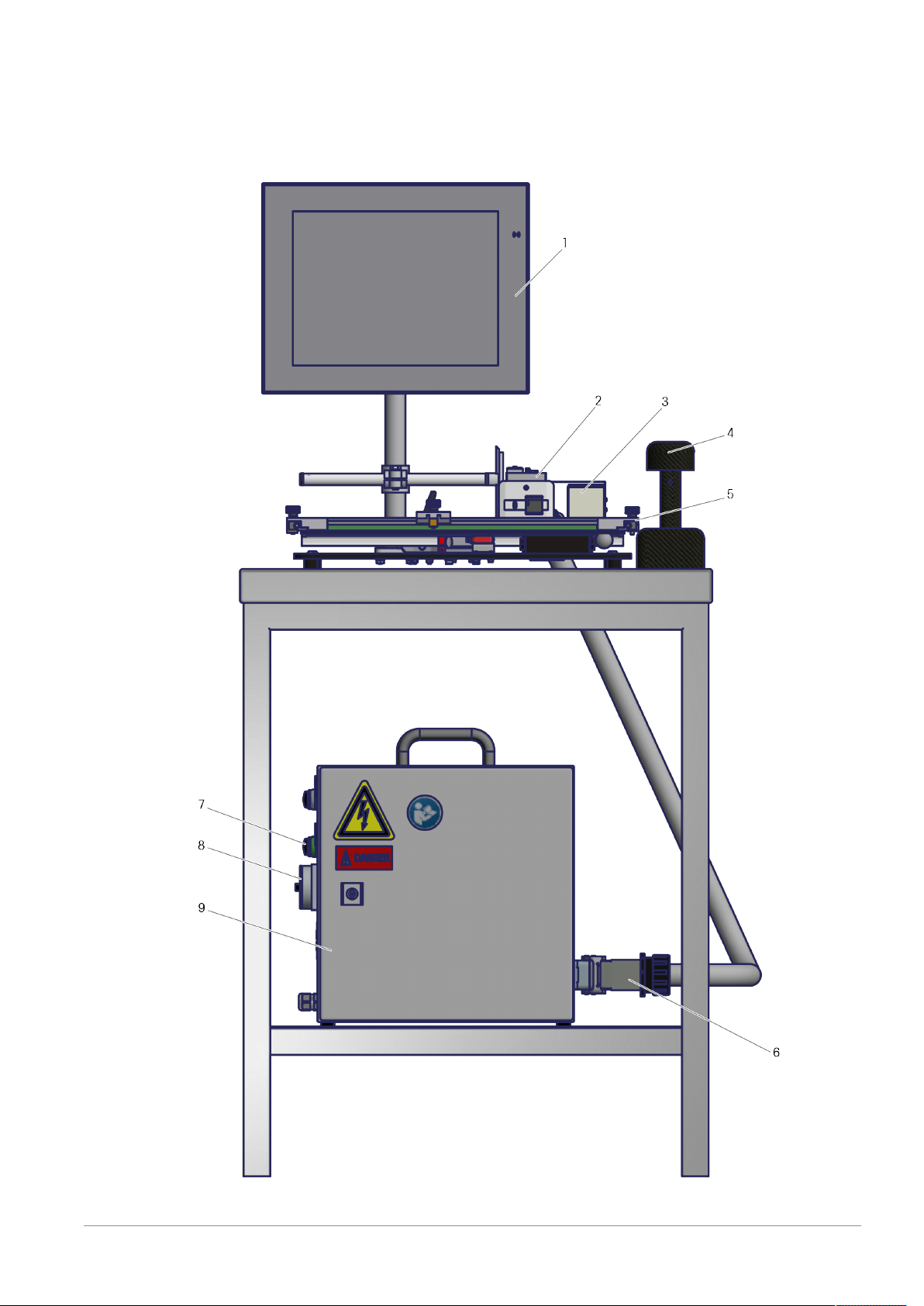
3.2 Equipment Description
The following image is a simplified representation of a T2611 Manual Serialization with a Bluhm printer
(standard option) and an SMC. Other configurations, for example, with a Wolke printer, are possible upon
request. The overall design and principle of operation is the same. Specifications may vary depending on
the selected configuration.
T2611 with Bluhm printer and SMC
T2611 - Manual Serialization - User Manual - Document Version E 11 / 40
Page 12

# Description
1 15" Display Unit
The display unit includes an integrated IPC for PLM/PLM direct.
2 Printer
The printer prints serialized information onto the cartons. The printer communicates to the PLM
or to the PLM direct via Ethernet.
The print head can print a maximum print height of 12mm. Human Readable Text and
Datamatrix Code must fit into this height.
3 Smart Camera
Type320 with 8mm lens
Field of view: 90mmx70mm. All serialized information (Human Readable Text and
Datamatrix Code) must be within the field of view. The maximum print height is 12mm.
4 Bluetooth Hand Scanner
The hand scanner is used for the decommissioning of serial numbers.
5 Moving Plate
The moving plate moves above the fixed ground plate. The carton is placed on the moving plate
and moved manually by the operator. An encoder is mounted to the ground plate and allows
proper printing independently from the speed of the moving plate.
6 Harting Connector
Connects the control cabinet with the devices. Allows operators to easily disconnect the cabinet.
Status light for power supply
7
Main switch
8
9 Control Cabinet
Dimensions (WxHxD): 380mmx422mmx210mm
LEDs at Bluhm printer
As an example, the following picture shows the status LEDs of a Bluhm printer (standard option).
LEDs at Bluhm printer
1
3
Network
Sensor
Ink
2
Status
4
For details on the printers refer to the respective printer manuals.
12 / 40 T2611 - Manual Serialization - User Manual - Document Version E
Page 13

4 Transporting, Moving, and Storage
WARNING
Lift the system only under the supervision of a competent person who has
sufficient and applicable training.
WARNING
Obey the applicable safety regulations at all times during lifting operations.
NOTICE
METTLER TOLEDO accepts no liability for damage to the system caused by
using incorrect lifting procedures or inadequate lifting equipment.
NOTICE
The equipment can be considerably damaged by shocks or by dropping. Be
careful when moving the equipment and do not tip it or drop it.
4.1 Transporting the Equipment
WARNING
If you unplug the Harting connector to split control cabinet and moving plate
for transport, use carefulness since the connection is very tight.
WARNING
If the equipment is not properly secured when transporting, it may tip over or
drop. This may cause serious injury or death.
Only qualified personnel are allowed to transport the equipment. Secure the
equipment and keep it upright when transporting. Use an appropriately sized
forklift or similar cart.
Make sure that the transport protection is locked and
the moving plate can't move before transporting the
device.
Follow these instructions when transporting the equipment in its original packaging:
• Do not unpack the equipment from its crate or other packaging before reaching the location where it is
to be installed.
• Use lifting and transporting equipment that has the appropriate loading capacity.
T2611 - Manual Serialization - User Manual - Document Version E 13 / 40
Page 14

• Do not tilt or drop the equipment while transporting.
4.2 Storing the Equipment
Follow these instructions for storing the equipment:
• Until the equipment is installed, leave it upright in its original crate or packaging.
• Store the equipment in a clean, dry, climate-controlled room. This protects the equipment from physical
damage and harmful exposure to dirt, dust and moisture.
• Keep all electronic parts in the protective, anti-static pouches until they are used.
If you do not operate the system for some time and want to store it until you use it again, you need to do
the steps that follow:
1 Clean and sanitize the system according to the procedures of your company.
2 Make sure that every part of the system is dry.
3 Wrap the system in cling film or a similar packaging material.
4 Add applicable moisture-absorbing packages, such as desiccant (silica gel) inside the wrapped system.
5 Store the system in a dust-free and dry location in accordance with the environmental conditions below:
ð Temperature range: -10°C (14°F) to 50°C (122°F)
ð Relative humidity: 30% to 85% (non-condensing)
If you want to store the system while it is still packed in the crate after you have received it, follow step 5.
4.3 Unpacking the Equipment
Pharmacontrol Electronic GmbH supplies the equipment in a crate wrapped in plastic wrapping and
banding.
Pharmacontrol Electronic GmbH supplies the equipment attached to a wooden pallet. The pallet may or
may not be inside a wooden or cardboard crate.
Only unpack the equipment after it has reached its final destination.
NOTICE
Take care not to disturb the positioning of the components when removing the
wrapping.
Follow these steps to unpack the equipment:
1. Remove the plastic wrapping and banding.
2. Remove the sidewalls. Then, remove the top of the crate, wood support pieces, and the corner posts.
3. If applicable, remove and discard any blocks and metal brackets that attach the casters or adjustable
feet to the pallet.
4. Loosen and remove the nuts on the bolts which attach the machine feet to the crate. Then, remove the
bolts.
5. Follow the procedure in Moving the Equipment and Setting it in Place to lift the equipment off the pallet
and set it in place.
6. Carefully remove all shrink wrap, bubble wrap, and plastic strapping that may be around the
components of the equipment.
7. Bolts may loosen during shipment. Check to make sure that all of the bolts on the equipment are tight
and secure. Tighten any loose bolts.
8. Recycle or discard the packaging materials.
14 / 40 T2611 - Manual Serialization - User Manual - Document Version E
Page 15

5 Installation
5.1 Mechanical and Electrical Installation
WARNING
Electrical Damage
Switch off the control cabinet before you unplug the connector between the control cabinet
and the ground plate.
WARNING
Electrical Damage
Do not remove the handle from the control cabinet.
NOTICE
The main switch of the control cabinet shall be easily accessible and located between 0.6
m (2.0 ft) and 1.5 m (4.9 ft) above floor level.
Place the ground plate with printer and HMI on a stable ground (e.g. table).
For the electrical connection refer to the technical manual.
CAUTION
Cable between control cabinet and moving plate
Make sure that the cable between control cabinet and moving plate is placed safe and
that no tripping hazards occur.
Do not change the lower mechanical adjustments!
5.2 Setting up the Equipment
You need to have administrator rights for PLM for creating and setup of the 3 devices:
• Hand Scanner
• Smart Camera
• Printer
5.2.1 Set up the hand scanner
1. Go to System Settings and press Create/edit device
2. Press Add
3. Select "Honeywell_Scanner" and press OK.
T2611 - Manual Serialization - User Manual - Document Version E 15 / 40
Page 16

4. Fill in the field for device name "Hand Scanner Decommission" and press OK.
5.2.2 Set up the Smart Camera
The Smart Camera reads barcodes, data matrix codes and human readable text and compares it with the
data received from the PLM. When the data is valid, the item is further processed. If data is invalid, the item
will be discarded.
When creating the Smart Camera as a device in PLM, you can choose between two different class names:
• PCE_SMC
• PCE_SMC_PRC
The class has the additional parameter 'CommandTimeOut'.
The Smart Camera is editable under System Settings > Edit device settings > (<select
Smart Camera tab>). At the tab menu on the top you can switch between the screens.
System Settings > Edit device settings > (<select smart camera tab>)
Edit the settings at the input fields and dropdown lists.
The table below gives an overview of these settings:
Parameter Description Default value Allowed values
Name Name that has been assigned in the
Camera Alphanumeric
device management settings.
Description Optional description - Alphanumeric
boxingRank Hierarchy level (1) Unit Drop-down list
internalFormats Camera manages internal formats Chechmark set Checkbox
automaticMode When automatic mode is active, manual
Checkmark set Checkbox
operation of the device is not possible.
needDeviceFormat Device appears on the line format Checkmark set Checkbox
showDeviceFrame Activates/deactivates the display of the
Checkmark set Checkbox
device in the menu “overview”.
logLevel Setting of how much data is logged
INFO Drop-down list
(TRACE/DEBUG/INFO/WARN/ERROR)
PLCName Name of the camera for the PLC Cam1 Drop-down list
readerMode PRINT_INSPECTION
PRINT_INSPECTION Drop-down list
AGGREGATE_READER
LINKING_READER
AGG_INSPECTION
LINEFORMAT
autoVerifyAggUnit Possibility of combining with one reading
Checkmark not set Checkbox
process the verification and commission
into the database.
16 / 40 T2611 - Manual Serialization - User Manual - Document Version E
Page 17

preAggregationReject
autoReject Relevant for aggregation modes only with
forceAggCache The parameter is relevant only for aggre-
useWildcards Activates/deactivates the transfer of the
ConnectGui Activates/deactivates the image
ip IP address of the device 192.168.100.215 Valid IP address
errorImages Activates/deactivates the permanent
debugStatistics
CommandTimeOut Maximum waiting time (milliseconds) for
Units scanned by aggregation reader are
validated direct after read and rejected by
PLC. Default the validation process starts
with the covering box close signal
(content size is reached or close button)
activated setting "autoVerifyAggUnit". If
enabled, the units are not added to aggregation cache if the reading was bad/
incomplete. There is no UI notification in
this case.
gation reader modes with enabled
delayed aggregation where the aggregation cache is closed only after "aggregationReady" signal from PLC. If enabled,
any bad/incomplete/good reading will be
pushed into the delayed aggregation
queue and must be consumed by an
external aggregation ready/abort signal.
Otherwise only good reading is
consumed.
serial number through a placeholder
(*****) it is only checked for length, not
for contents.
processing on the camera
storage of SMC error images in the PCE
Line Manager database.
Stores communication between the PCE
Line Manager and the camera in txt data.
Only for error searches, otherwise this
should be switched off.
response from the device after sending a
command (for example, reference code).
Checkmark not set Checkbox
Checkmark not set Checkbox
Checkmark not set Checkbox
Checkmark set Checkbox
Checkmark set Checkbox
Checkmark not set Checkbox
Checkmark not set Checkbox
5000 Alphanumeric
5.2.2.1 Setting up a Product in SMC
This chapter describes how to set up a product in the Smart Camera. Some step sequences have to be
repeated in order to set several fields. For this the steps are numbered.
Step Action
1 Press Home.
T2611 - Manual Serialization - User Manual - Document Version E 17 / 40
Page 18

Home
Step Action
2 Select the camera bar.
The following screen appears (It may be that the software automatically skips this screen. In this case you
do not need to press menu at this point and you see the subsequent screen):
Home > (<select smart camera bar>)
Step Action
3 Press Menu.
The following screen appears:
Home > (<select smart camera bar>) > Menu
Step Action
18 / 40 T2611 - Manual Serialization - User Manual - Document Version E
Page 19

4 Press Product management.
The following screen appears:
Home > (<select smart camera bar>) > Menu > Product management
Step Action
5 Press New product.
The following dialog (New product name) appears:
Home > (<select smart camera bar>) > Menu > Product management > New product
Step Action
6 Enter a unique product name.
7 Press Enter on the keyboard.
T2611 - Manual Serialization - User Manual - Document Version E 19 / 40
Page 20

The following dialog (Live image) appears:
Home > (<select smart camera bar>) > Menu > Product management > New product > (enter product name) > Enter
(at the keyboard)
Step Action
8 Select live Image.
9 Place item underneath the Smart Camera.
The following screen appears:
Home > (<select smart camera bar>) > Menu > Product management > New product > (enter product name) > Enter
(at the keyboard) > Live Image
Step Action
10 Select Next.
20 / 40 T2611 - Manual Serialization - User Manual - Document Version E
Page 21

The following dialog (Control) appears:
Home > (<select smart camera bar>) > Menu > Product management > New product > (enter product name) > Enter
(at the keyboard) > Live Image > Next
Step Action
11 Press OCV control.
The screen looks as follows:
Home > (<select smart camera bar>) > Menu > Product management > New product > (enter product name) > Enter
(at the keyboard) > Live Image > Next > OCV control
To set the control window for the expiry date proceed as follows.
Step Action
12 Move the yellow control window in a way that it is arranged around the expiry date. See below.
To set the control window you can use the navigation arrow keys as described in the following table. You
can also move the control window and adjust its borders by dragging and dropping the borders.
Button Function
Navigation arrow keys for functions at the modes. The mode is
selected at the button in the middle.
Button Mode
T2611 - Manual Serialization - User Manual - Document Version E 21 / 40
Page 22

‘scrolling’ The control window can be moved using the arrow keys.
‘zoom in’ The control window can be enlarged using the arrow keys.
‘zoom out’ The control window can be reduced using the arrow keys.
Step Action
13 After the control window is set to the right position, press OK to confirm.
The following Dialog (Threshold) appears:
Home > (<select smart camera bar>) > Menu > Product management > New product > (enter product name) > Enter
(at the keyboard) > Live Image > Next > OCV control (arrange control window) > OK (set threshold)
Step Action
14 Move threshold in a way until you can clearly read the font.
15 Then press OK to confirm.
The following dialog (Window with measuring arrows?) appears:
Home > (<select smart camera bar>) > Menu > Product management > New product > (enter product name) > Enter
(at the keyboard) > Live Image > Next > OCV control (arrange control window) > OK (set threshold) > OK
Step Action
16 Select Yes.
22 / 40 T2611 - Manual Serialization - User Manual - Document Version E
Page 23

After pressing Yes, the following dialog (Font Memory) appears:
Home > (<select smart camera bar>) > Menu > Product management > New product > (enter product name) > Enter
(at the keyboard) > Live Image > Next > OCV control (arrange control window) > OK
At this dialog you have to choose the font memory you would like to use.
Step Action
17 Select ocrb.
The following dialog (Prepare another control?) appears:
Home > (<select smart camera bar>) > Menu > Product management > New product > (enter product name) > Enter
(at the keyboard) > Live Image > Next > OCV control (arrange control window) > OK (set threshold) > OK > Yes
(select font memory)
To set another control window for the <LOT> field you have to repeat the steps (11-15).
Step Action
18 PressYes. (You are automatically led back to proceed from step 11)
19 Repeat steps 11–15
T2611 - Manual Serialization - User Manual - Document Version E 23 / 40
Page 24

Home > (<select smart camera bar>) > Menu > Product management > New product > (enter product name) > Enter
(at the keyboard) > Live Image > Next > OCV control (arrange control window) > OK (set threshold) > OK > Yes
(select font memory)
Step Action
20 Select No.
The following screen appears:
Home > (<select smart camera bar>) > Menu > Product management > New product > (enter product name) > Enter
(at the keyboard) > Live Image > Next > OCV control (arrange control window) > OK (set threshold) > OK > Yes
(select font memory) > No
At this screen you see the calculated position of measurement lines.
Step Action
21 Press Next to leave the screen.
24 / 40 T2611 - Manual Serialization - User Manual - Document Version E
Page 25

After pressing next you get to the following screen:
Home > (<select smart camera bar>) > Menu > Product management > New product > (enter product name) > Enter
(at the keyboard) > Live Image > Next > OCV control (arrange control window) > OK (set threshold) > OK > Yes
(select font memory) > No > Next
You can return to production or add a new control window. To add another control window press Add
control window. You will be redirected to step 11. To return to production close the Product management
dialog by pressing x and press Production at the Main Menu dialog.
5.2.2.2 Final Result for SMC setup
The complete configuration in the end should look like following screenshot:
• DM0 = Data Matrix Search Window
• OCV0-x = Optical Character Verification for GTIN, Batch, Expiry, Serial and others
• The wide DM0 window is used to catch the Data Matrix Code. OCV windows will be moved related to
DM Code.
For optimization of DM Code reading results please adjust the two values marked red:
• Additional information such as linkage of windows or teaching characters for OCV will be found within
the user manual "Optical Character / Code Verification 7.xxx".
T2611 - Manual Serialization - User Manual - Document Version E 25 / 40
Page 26

5.2.3 Set up the printer
1. Go to System Settings and press Create/edit device
2. Press Add
3. Select your printer and press OK.
4. Assign a useful name to your printer (for example: "BluhmWeber Printer").
NOTE: The printer will not be shown within the device list after it was created.
26 / 40 T2611 - Manual Serialization - User Manual - Document Version E
Page 27

6 Operation
6.1 Starting the Equipment
1. Turn on the T2611 at the main switch.
2. Log in with user name and password (for details see PLM user manual).
6.2 Setting the Box Size
Before starting a production run, you have to set the box size.
Top view
1
3
5
1 Insert the box (1).
2 Move the first guiding rail (2) to the box (1).
3 Tighten the screw (3).
4 Move the second guiding rail (4) towards the printer. Ensure that the distance between the box (1) and
5 Tighten the screw (5).
T2611 - Manual Serialization - User Manual - Document Version E 27 / 40
Box
Screw
Screw
the printer front plate is approximately 2mm to 5mm (see picture below).
2
4
Guiding rail
Guiding rail
Page 28

Distance between Box and Printer
When setting the box size, you have to ensure that the distance between the box (2) and the printer front
plate (1) is approximately 2mm to 5mm.
Side view
1
Printer with printer front plate
6.3 Workflow
There are two principal workflows which can be handled with the T2611:
• Workflow 1: Print - Verify - Commission
With this workflow you can serialize the requested cartons and all good cartons will be part of the order.
• Workflow 2: Decommission
With this workflow you can take cartons you do not want to ship out of an order.
NOTE: In the following chapter, the workflows are described with the help of a Bluhm printer. Other printers
are possible. The overall procedure at the T2611 is the same.
NOTICE
Malfunction and damage due to faulty handling
This chapter only provides basic knowledge on the components of the T2611.
For details on the correct handling of the PLM refer to the PLM manual.
For details on the correct handling of the SMC software refer to the SMC OCV manual.
For details on the correct handling of the printer refer to the respective printer manual.
6.3.1 Workflow 1: Print - Verify - Commission
2
Box
1 Create your required label templates.
Depending on the printer model, you can use Bluhm "idesign touch", for example.
2 Adjust the trigger point in accordance with the printer manual.
28 / 40 T2611 - Manual Serialization - User Manual - Document Version E
Page 29

3 Create a line format and the devices (printer, SMC) in the PLM (see PLM user manual for details).
4 Create the hand scanner device (globally, see PLM user manual for details).
5 Press Home. Select the Smart Camera by pressing on the respective tab.
T2611 - Manual Serialization - User Manual - Document Version E 29 / 40
Page 30

6 Teach-in the camera (see OCV manual).
NOTE: Before you can teach-in the camera, you have to provide a product that contains the printed
information that the camera has to inspect. To do so, you can start a test run via PLM (see PLM user
manual for details).
NOTICE
It is very important that the Datamatrix searching area extends the maximum horizontal
way (see figure below).
7 Create or import an order.
8 Start the order.
9 Navigate to the camera menu to see the reading result of the camera (Home > Smart Camera device
tab).
10 Place the carton on the moving plate.
11 Move the moving plate to the start position (left end, strobe lights are off).
NOTICE
The carton print side should be as flat as possible to avoid bad printing.
12 Start moving the plate to the right end.
Move the plate consistently and do not stop until you reach the right end.
While the plate is moving, the strobe lights are on and the printer prints the requested serial number
onto the carton. The camera verifies the code with the serial number and the human readable characters
during the movement of the carton.
Move the plate back to the starting position on the left end.
ð If the camera was able to read the code and the reading result was good, you can see a green frame
and the strobe lights are off.
ð If the camera was able to read the code and the reading result was bad, you can see a red frame.
NOTICE
The actual working speed for cartons may vary and depends on various factors (e.g. print
quality, size, carton surface, camera settings).
30 / 40 T2611 - Manual Serialization - User Manual - Document Version E
Page 31

NOTICE
If you remove the carton before the reading has been finished, an offset of serial number
might occur. In that case stop and restart production to get synchronization again.
13 Place the next carton on the moving plate and start moving the plate to the right end and back to the left
end.
ð The reading result will be displayed.
14 Go on with all cartons you need.
15 Stop the order.
ð The machine is ready for the next order or for shut down.
6.3.2 Workflow 2: Decommission
1 Select the hand scanner for decommissioning.
2 Open the requested order and select Show Hierarchy.
3 Scan the carton.
ð The result will be shown at the PLM.
4 Stop the order.
ð The machine is ready for the next order or for shut down.
T2611 - Manual Serialization - User Manual - Document Version E 31 / 40
Page 32

6.4 Shutting down the Equipment
1. Shut down PLM/PLM direct by selecting the upper right user button.
2. Select PLM shutdown.
3. Turn off the main switch.
32 / 40 T2611 - Manual Serialization - User Manual - Document Version E
Page 33

7 Maintenance
7.1 Changing the Printer Cartridge
NOTICE
Malfunction and damage due to faulty handling
This chapter only provides basic knowledge. For details on the correct handling of printers
refer to the respective printer manuals.
NOTE: As an example, this chapter explains changing the printer cartridge of a Bluhm printer.
1 Release the lever and remove the printer cartridge.
2 Insert a new printer cartridge into the printer.
T2611 - Manual Serialization - User Manual - Document Version E 33 / 40
Page 34

3 Tighten the printer cartridge with the help of the lever.
34 / 40 T2611 - Manual Serialization - User Manual - Document Version E
Page 35

8 Cleaning
8.1 Visual Inspection and Cleaning of the System
Recommended inspection
interval
Daily Perform a general visual inspection.
What needs to be done?
WARNING
Cleaning the system when it is hot may cause severe damage.
Only clean the system with liquid when it is cooled down to room temperature.
WARNING
Careless cleaning may cause severe damage.
Never use a high pressure jet to hose down the system.
Do not use caustic cleaning agents containing solvents to clean the system and the
terminal. Never use pure alcohol or concentrated acid or lye.
Use particular care when cleaning in order to avoid damage and, above all, to prevent
water from entering the system.
• Clean the system and terminal using soft cloths dampened with a mild solution of soap and water or a
commercially available glass and plastic cleaner.
8.2 Visual inspection of Gaskets/Seals
Recommended inspection
interval
Monthly Perform a general visual inspection.
What needs to be done?
8.3 Cleaning the Touch Screen
The display surface is made from glass and the casing from stainless steel. To ensure efficient operation,
the surface of the touch screen should be cleaned regularly. Only special cleaning wipes and cleaning
agents should be used:
• Commercial cleaners for computer equipment
• Alcohol-based disinfectants
CAUTION
Solvents can damage the display.
Never use diluting agents, benzene, abrasives or other strong solvents, as these can
damage the display!
8.4 Cleaning the Print Head
Clean the print head every 30 minutes or if the print quality is not sufficient.
T2611 - Manual Serialization - User Manual - Document Version E 35 / 40
Page 36

To clean the print head, press a lint free cloth on the print head. Do not move the cloth, just press it down.
8.5 General Advice on Stainless Steel Maintenance
Stainless steel generally provides much better protection against corrosion when compared with steel or
aluminium. Stainless steel, however, does not always remain rust-free. Stainless steel can also become
dirty or rusty to some extent, depending on the operational use and the conditions in the working
environment. The most common causes are surface rust (fine iron particles in the air), active gases, the
accumulation of sediments and the build-up of salts. These superficial damages can be easily removed by
using a stainless steel spray daily. After cleaning with soap and water, you should check that the residue is
washed off with a suitable amount of water.
36 / 40 T2611 - Manual Serialization - User Manual - Document Version E
Page 37

9 Disposal
In conformance with the European Directive 2012/19/EU on Waste Electrical and
Electronic Equipment (WEEE) this device may not be disposed of in domestic waste. This
also applies to countries outside the EU, per their specific requirements.
Please dispose of this product in accordance with local regulations at the collecting point
specified for electrical and electronic equipment. If you have any questions, please contact
the responsible authority or the distributor from which you purchased this device. Should
this device be passed on to other parties, the content of this regulation must also be
related.
T2611 - Manual Serialization - User Manual - Document Version E 37 / 40
Page 38

10 Technical Data SMC Series 3
The following specifications apply to the SMC Series 3.
Housing Aluminum,
Dimensions as example for camera type no. 320 and housing size 21: LxWxH:
91mmx55mmx55mm
Protection of housing IP65: dust-tight and protection against water jets. No ingress of dust. Water-
protected by a nozzle against enclosure from any direction.
Power supply 24ˆV DC, min. 20V, max. 28V,
Current during start up: max. about 1A,
Current during operation: about 150mA
Image processing Internally, with special machine vision processor.
Inputs 3 inputs 24VDC, max. 28V permanent, response threshold: High: about
>13V, Low: about <7V
Outputs 4 Outputs 24VDC, type PNP, max. 100mA permanent, max. 400mA peak
short-circuit-proof, protected against overload and protected against external
voltage
Interface Ethernet 100/1000Mbit/s, LAN
Interface RS-232
Illumination White LEDs in flash operation
Standard lens (1) C-Mount, 12mm focal length
Standard distance
between object and
camera housing (1)
Standard visible area (1) LxW: 95mmx71mm
Camera inclination angle 0-10 degrees in relation to vertical and product horizontal
Environmental conditions
at transport and storage
Environmental conditions
at operation
Weight 430g
135mm
-20°C (-4°F) to +80°C (+176°F),
Max. humidity 90%, non-condensing
0°C (+32°F) to +50°C (+122°F),
Max. humidity 80%, non-condensing
(1) Other configurations are available.
38 / 40 T2611 - Manual Serialization - User Manual - Document Version E
Page 39

Intentionally left blank
T2611 - Manual Serialization - User Manual - Document Version E 39 / 40
Page 40

Pharmacontrol Electronic GmbH
Harzstraße 1
64646 Heppenheim, Germany
Tel. +49 6252 6736 0
Fax +49 6252 6736 111
www.mt.com
Subject to technical changes.
© Pharmacontrol Electronic GmbH 02/2019
T2611 - Manual Serialization - User Manual - Document Version Een
www.mt.com/pce
For more information
 Loading...