

Page 1
Enter
Setup
Reset
Step
METTLER TOLEDO
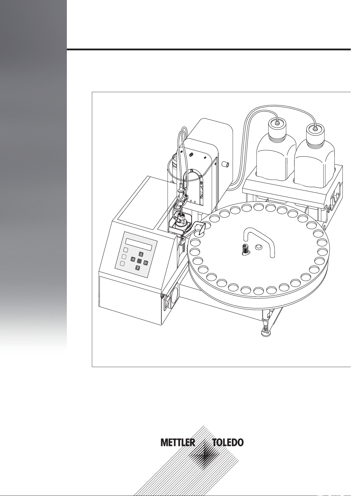
SC30
Sample Delivery and Cleaning Unit
SC30
Operating Instructions
Page 2

Page 3

Table of contents
Introduction1 5
Safety Measure2 6
Layout of the Instrument3 7
Installing SC304 9
Operating of the SC unit5 23
Care and Maintenance6 32
Disposal 7 35
The Instrument3.1 7
Terminal3.2 8
Installing the Power Purge Unit (PPU)4.1 13
Sample Vials4.2 14
Connecting SC unit with the Density Meter (DM)4.3 16
Connecting the SC unit with the Refractometer (RM)4.4 17
4.5 19
4.6 21
Connecting the SC unit with the Density Module (DX) combined
with the Refractometer (RM)
Connecting the SC unit with the Refractive Index Modules (RX)
combined with the Density Meter (DM)
Registering the SC unit in the measuring instrument 5.1 23
Activating additional equipment5.2 23
Useful settings for the measuring instrument5.3 23
Setting up the SC unit5.4 24
Adjusting the measuring instrument5.5 26
Entering an Adjustment method in the measuring instrument5.5.1 26
Performing an adjustment5.5.2 27
Performing the Cell Test (with air) for the Density Meter5.6 28
Entering a measuring method5.7 28
Performing an Offline Cleaning5.7.1 28
Activating Automatic Error Detection5.7.2 28
Setting the Sampling Speed5.7.3 29
Running a pre-defined sample series5.8 29
Defining series5.8.1 30
Using viscosity correction5.8.2 30
Performing a instrument test with a known liquid standard5.8.3 31
Using error detection5.8.4 31
Daily Performance Check6.1 32
Periodic Performance Check6.2 33
Adjusting the Sampling Mechanism6.3 33
Error Messages and Malfunctions8 36
Technical Specifications9 37
Standard Equipment10 38
Connection tubes10.1 40
Optional Accessories11 41
Table of contents 3
Page 4

Page 5

1Introduction
The Sample Delivery and Cleaning Unit turns your METTLER TOLEDO Density Meter DM40 / DM45 DeltaRange /
DM50 or Refractometer (RM40 / RM50) or combined with the Refractive Index Modules (DM/RX) or Density
Modules (RM/DX) into a fully automated measuring system for the quality control of liquid samples.
Such a measuring system is capable of
●
measuring series of samples as well as adjusting and checking the instrument automatically at the push of
a button.
●
detecting measuring errors automatically or ruling them out in advance:
•
The samples are pushed and not aspirated (as is often the case in other systems) into the measuring
cell. In most cases this will exclude erroneous measurements due to air bubbles.
•
The sampling nozzle is completely cleaned and dried inside and out after each measurement, depending
on the sequence settings. Sample carryover can be safely ruled out.
•
Before measurement, the samples can be stored in sealable sample vials. The vials are opened by the
Sample Delivery and Cleaning Unit only just before the measurement takes place. A change in the sam
ple's properties due to evaporation or contamination is, therefore, not possible.
•
The most frequent sources of error in measuring refractive indices and densities are air bubbles, inhomo
geneous samples, solvent residues in the system, or scattered light caused by solid particles. These are
automatically recognized by the system and the user is warned accordingly.
●
performing multiple measurements of the samples automatically, and directly displaying and printing the
mean and standard deviation of individual results.
●
preventing permanent contamination of the measuring cell. The measuring system can be rinsed automati
cally with up to two solvents: the first solvent removes the sample; the second solvent is a solvent of high
vapor pressure in order to dry the entire system. Both solvents are mixed with air and pumped through the
system at high speed. The resulting pulsating flow causes a mechanical and thus very effective cleaning.
●
fulfilling special requirements:
•
The SC unit is able to handle very highly viscous samples. The high pressure built up by the peristaltic
pump used to move the sample into the measuring cell and back into the vial makes it possible to mea
sure samples with a viscosity of up to 30'000 mPa·s.
•
The sampling speed of the SC unit may be adjusted very accurately. If small vials are used for the sam
ples it is possible to perform density or refractive index measurements of samples that are available in
small quantities only.
•
By equipping the SC unit with a highly corrosion resistant sampling nozzle made of Hastelloy (option),
the system is able to handle very aggressive samples such as concentrated hydrochloric acid.
•
The SC unit is able to handle samples which contain particulate material of a small grain size. If the grain
size exceeds 0.4 mm, however, the SC unit needs to be equipped with an external drain valve
(ME51327346).
●
returning the samples to the vial after the measurements. This setting is a must when using the heated ver
sion, to ensure that the sample doesn’t leave the heated area (risk of solidification). The built-in sample
recovery function pushes the samples back into the vials after the measurements (the shortest and quickest
way to empty the cell!).
Thus, the SC unit helps you to reduce the workload associated with measuring densities and refractive indices,
to ensure reliable results and to increase safety in the workplace.
5Introduction
Page 6
2Safety Measure
These instruments have been tested for the applications documented in the appropriate operating instructions.
However, that does not absolve you of the responsibility to check for yourself the suitability of the products sup
plied by us for the procedures and purposes for which you intend to use them. You should therefore observe the
following safety measures.
Measures for your protection
●
Ensure that you plug the supplied power cable into a socket that is grounded! In the
absence of grounding, a technical fault could be lethal.
●
Only use the power supply which was supplied with the device.
Risk of electric
shock
●
Never work in an environment subject to explosion hazards! The housing of the
instrument is not gas tight (explosion hazard due to spark formation, corrosion
caused by the ingress of gases).
●
Risk of explosion
Test highly combustible, poisonous or corrosive substances under an extractor
hood and follow the normal laboratory rules and precautions.
●
Wear safety glasses and other items for personal safety (protective gloves and
clothing) when working with the equipment. The samples, the rinsing liquids and
the air are under pressure when working with the system. A splashing out of liquids
may therefore not be excluded.
●
Be especially careful when measuring highly viscous samples. The overpressure
created in the vial during sampling may cause the sample to splash out if the sam
pling nozzle is quickly moved out of the membrane.
●
Never work without having the protective cover mounted on the equipment. The
movable parts of the equipment may hurt you.
●
When using chemicals and solvents, comply with the manufacturer's instructions
and the general lab safety rules!
Risk of corrosion
●
If the instrument is not going to be used for a longer period of time, clean the diaphragm pump and tubing
connections by rinsing the instrument with water (for more information about rinsing the instrument, refer to
"Manual operation: Automation> Action: Rinse" in your Operating Instructions of your measuring instru
ment).
●
We recommend storing the instrument in the cardboard box in which it was delivered.
Only have the instrument serviced by an authorized METTLER TOLEDO Service agent!
6 Safety Measure
Page 7
3Layout of the Instrument
PPU
PPU IN
PPU
Enter
Setup
Reset
Step
METTLER TOLEDO
SC30
3.1The Instrument
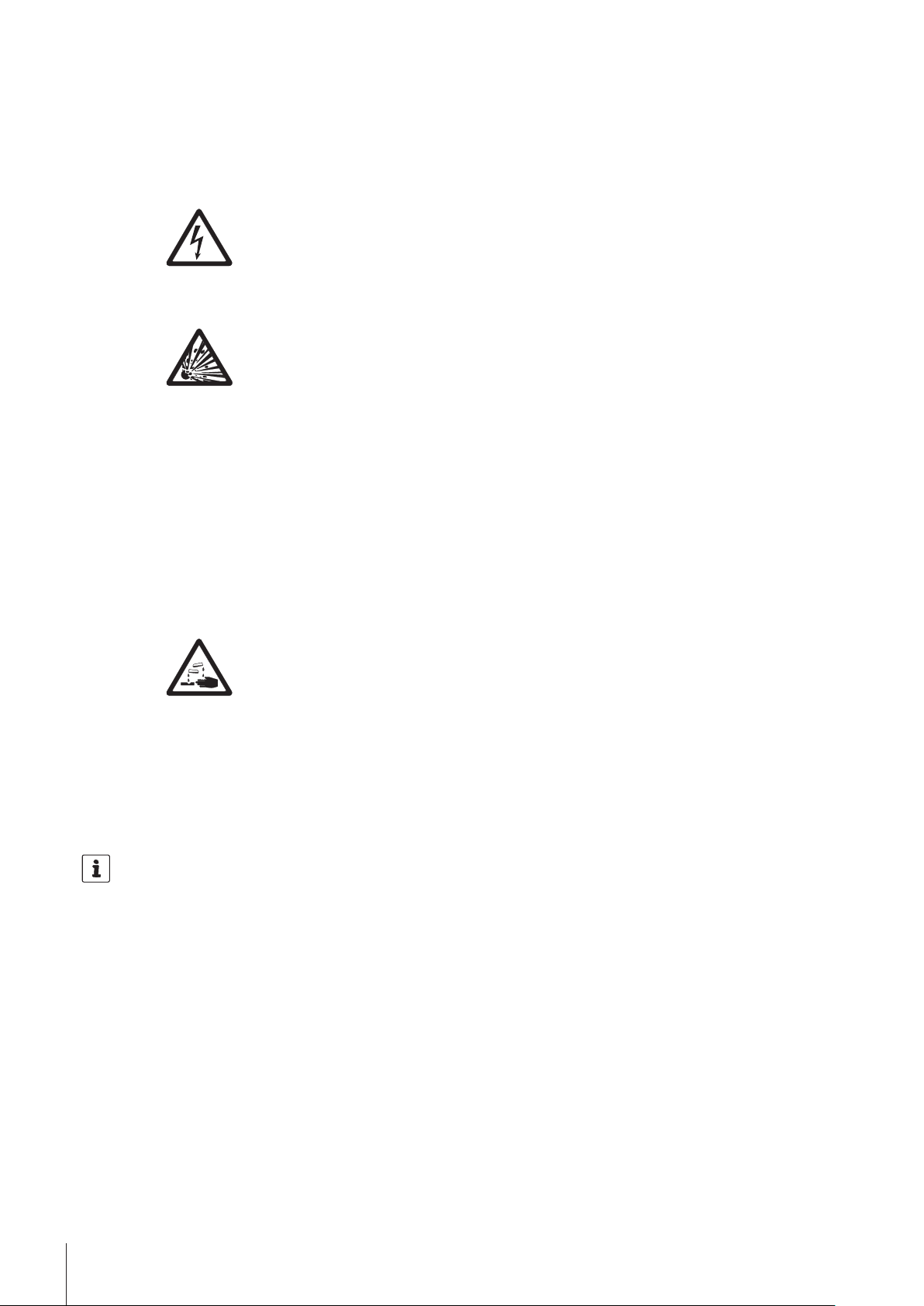
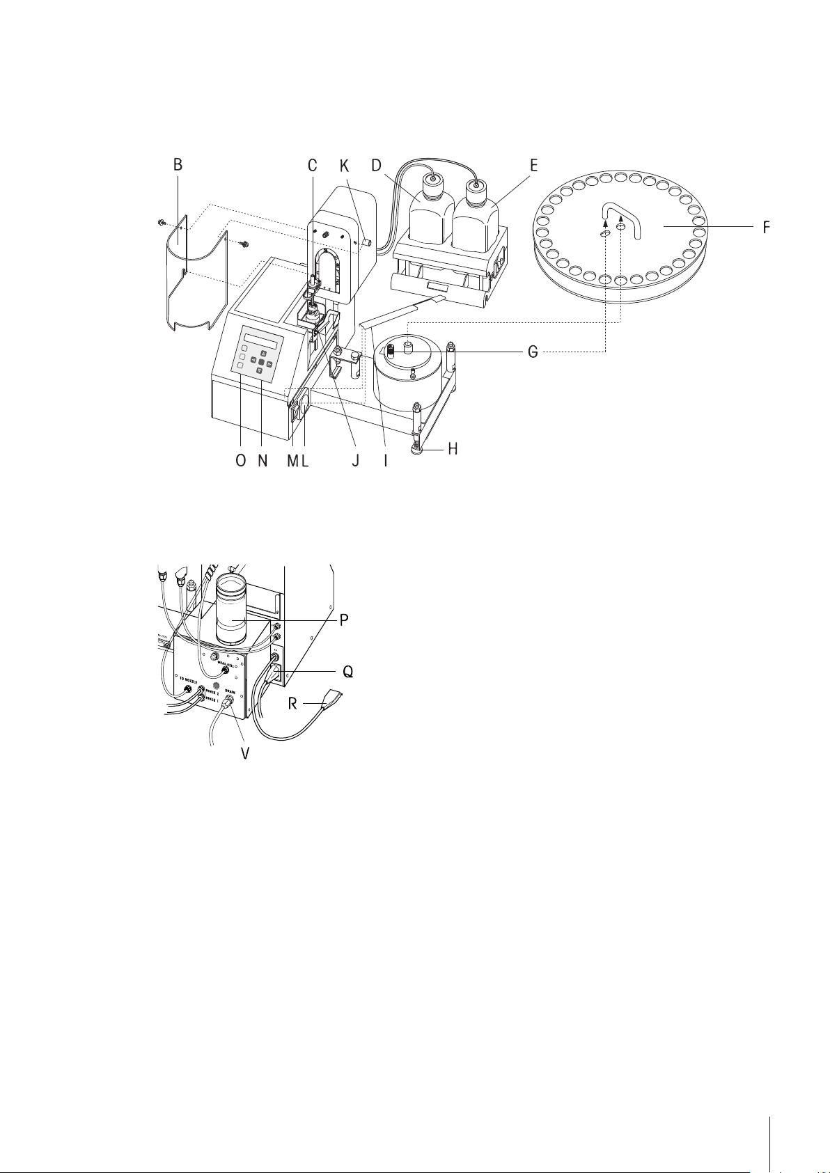
SC30 Overview
A Peristaltic pump .
To build up the overpressure for sampling and sample recovery
B Protective cover
The cover protects the user from movable parts (sampling nozzle).
7Layout of the Instrument
Page 8
C Sampling nozzle
EnterSetup
Reset
Step
METTLER TOLEDO
D Rinsing liquid 1 (solvent capable of dissolving the samples, e.g., water)
E Rinsing liquid 2 (highly volatile solvent, e.g., acetone)
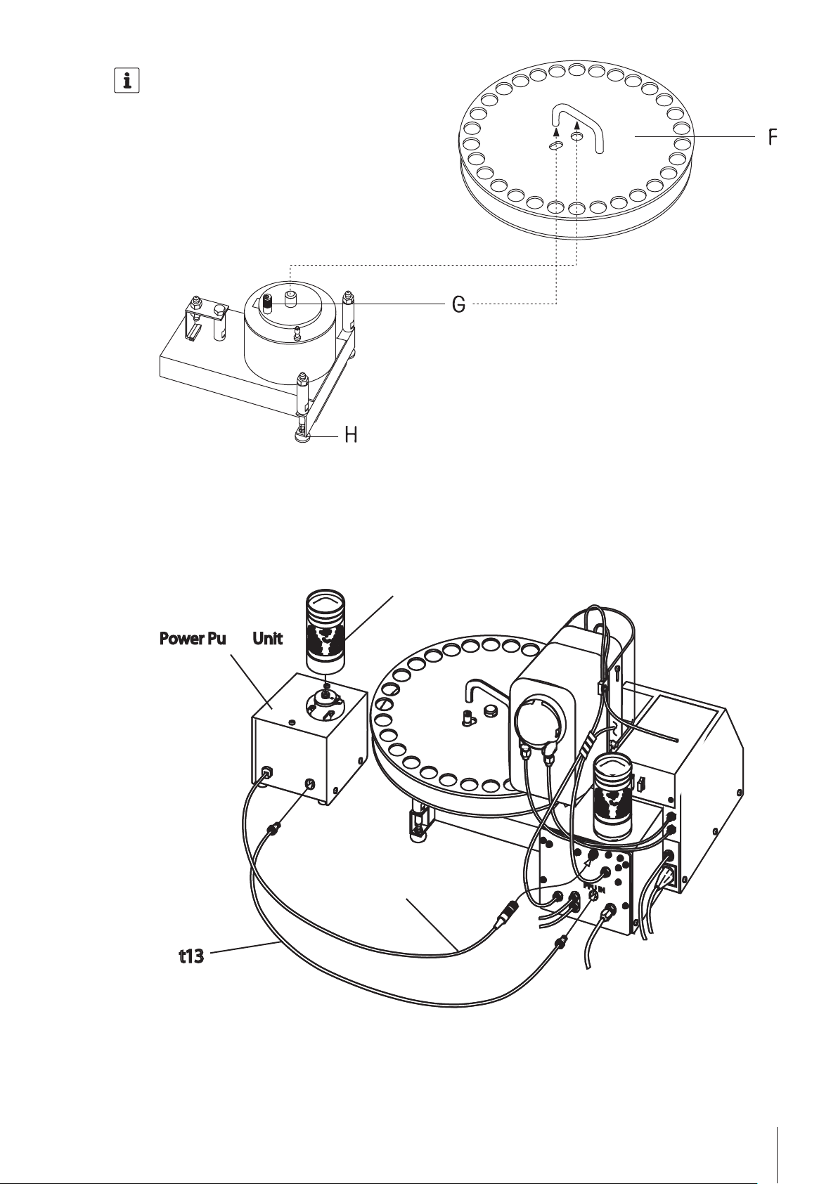
F Turntable for 30 samples
G Transportation pin for turntable
This pin is eccentric and allows adjustment of the turntable.
H Foot (height adjustable)
I Protective cover for power switch and ventilator
J Rinsing pot
This is where the sampling nozzle is cleaned and dried after the measurements.
K Potentiometer to adjust the sampling speed
L Air filter
M Power switch
To switch the SC30 and the connected instrument on and off.
O Terminal
P Desiccator
To dry the measuring cell and the tubing. After a measurement and before an adjustment air is
pumped through the system. This air is drawn in through the desiccator (filled with silica gel) and
thereby dried.
Q Power supply
Connect the power cable here. The instrument automatically adjusts to the mains voltage of your
country if this lies between 100 and 240 V.
R Power cable to connect the power supply of the measuring system.
T Serial interface
For connecting the measuring instrument with SC30.
V Connector for the waste tube
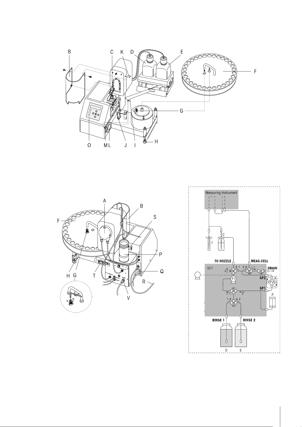
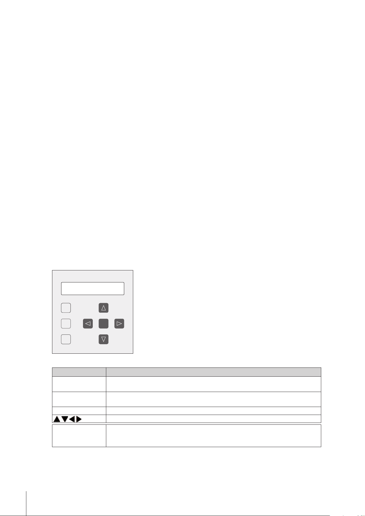
3.2Terminal
Buttons Description
Reset Stops all actions of the SC unit and aborts the running task on the main instrument
(emergency stop).
Setup The Setup menu is used to detect the SC unit at the measuring systemTo leave the "Set
up" menu, press Setup again.
Enter Confirms settings in the Setup dialog.
Selects the menu items in the "Setup" menu.
Step Rotates the turntable. If this key is pressed quickly, the turntable rotates one position
forwards (clockwise). If this key is pressed for more than 2 seconds, the turntable
rotates until position 1 is at the sampling position.
8 Layout of the Instrument
Page 9
4Installing SC30
Enter
Setup
Reset
Step
METTLER TOLEDO
SC30
PPU IN
PPU
The Sample Delivery and Cleaning Unit can be connected to all METTLER TOLEDO Density Meters (DM40/
DM45 DeltaRange/ DM50 Density Meters) and Refractometers (RM40/ RM50).
In the following there are instructions for installing the SC unit and to connect it to your measuring instrument.
SC unit front view
●
Put the protective cover (I) for the power switch and the ventilator in the designated holder.
●
Put the turntable (F) on the SC unit.
Make sure that the transportation pin (G) is located in the oval hole of the turntable.
SC unit rear view
●
Install the desiccator (P) on the SC unit.
●
Connect SC unit with the provided power cable (Q).
The power cable R can be used to connect your measuring system (see below).
9Installing SC30
Page 10
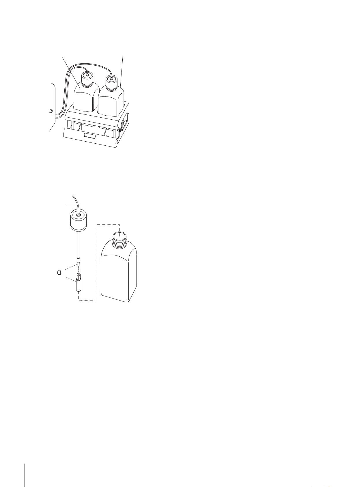
Rinsing
liquid 1
Rinsing
liquid 2
t1
t2
●
t1 / t2
Prepare the rinsing liquids.
Fill one bottle (rinsing liquid 1) with a solvent capable of dissolving your samples (e.g., water if you are
measuring aqueous solutions) and the other (rinsing liquid 2) with a highly volatile solvent (e.g., acetone).
●
Place the bottles in the holder.
●
Push the tubes for the rinsing liquids (t1 and t2) through the bottle's covers and install the filters (a). Screw
the covers onto the bottles.
●
Connect the tubes for the rinsing liquids to the SC unit (t1 to input "RINSE 1"; t2 to input "RINSE 2") and
screw them tight by hand.
10 Installing SC30
Page 11
PPU IN
PPU
t6
SC pump compartment view
/
●
Put an appropriate waste receptacle (e.g., a plastic canister, not included) under the lab table.
•
Put the screw and the plastic seal (ring) onto the thick waste tube (t10).
•
By hand, screw tube (t10) tightly onto the "DRAIN" connector.
•
Place the other end of the tube in the waste receptacle.
•
Caution! The waste receptacle may not be hermetically sealed! The air used for pumping and drying must
be able to escape unhindered!
●
Place an empty vial in a position before the vial holder.
●
Using the step key, position the vial just right of the sampling needle.
The sampling nozzle will not move when no vial is detected at this position!
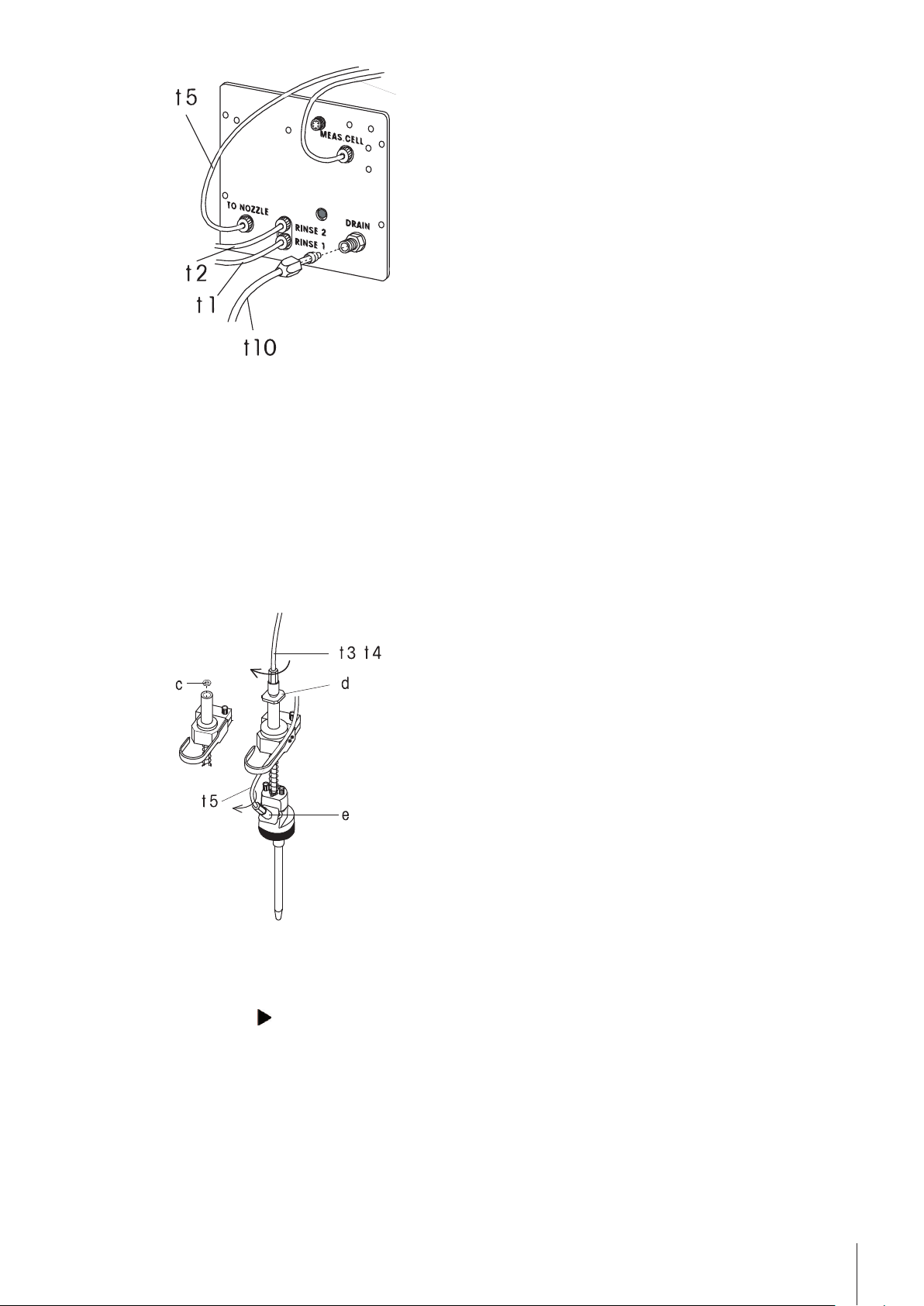
Sampling nozzle
Prepare the sampling nozzle as follows:
●
Switch on SC unit.
●
Press the -key.
- The sampling nozzle is going up.
●
●
●
●
Note: An audio-signal will sound if no vial is detected at the current position.
Press Reset as soon as the sampling nozzle is up between the rinsing pot and the turntable.
Completely screw the locknut (e) onto the tube (t5).
By hand, screw the tube (t5) clockwise into the sampling nozzle and tighten the locknut clockwise
Connect the other end of the tube (t5) to the "TO NOZZLE" port on the SC unit (see figure above: "SC pump
compartment view").
11Installing SC30
Page 12
●
By hand, tighten the connection well in the clockwise direction.
●
Place the seal (c, a white Teflon washer) into the thread above the sampling nozzle. The system will leak if
that Teflon washer is missing!
●
By hand, tighten the inlet tube of your measuring system (t3) on the sampling nozzle well in the clockwise
direction. Then tighten the locknut (d) well by hand in the clockwise direction.
Before the measurement the sampling nozzle is pressed onto the sample vial, and the sample vial is sealed
with a perfluoroelastomer seal. Air is pumped into the vial through a collar and the sample, due to the pressure
build up, is pressed into the measuring cell of the attached measuring instrument. If the sample recovery func
tion is activated, the sample is pushed back into the vial after the measurement. The sampling nozzle moves to
the rinsing pot where it is cleaned and dried inside and out.
Vial holder orientation
●
The horizontal orientation of the sample vial holder is adjusted with 2 screws (x).
Adjust the turntable
1 Close a vial with a cap and put it onto the turntable one position before the sampling position.
2 Press Step on the SC unit.
The vial moves into the sampling position.
3 Press the -key.
The sampling nozzles moves to the vial.
4 Press Reset before the needle of the sampling nozzle touches the membrane of the vial.
5 Verify the correct adjustment of the turntable by repeating the steps a) to d) above for at least 2 vials.
Repeat the adjustment if necessary.
12 Installing SC30
Page 13
z
Power Purge Unit㩷
y
t13
PPU IN
PPU
If the needle of the sample nozzle should not be in the center of the membrane, loosen the screw of the trans
portation pin (G) and turn it until the needle is located exactly in the center of the vial. Make sure not to touch
the turntable while adjusting it in order to avoid a faulty adjustment of the turntable due to the play of its drive.
Tighten the screw of the transportation pin (G).
4.1Installing the Power Purge Unit (PPU)
The Power Purge Unit (PPU) is an external diaphragm pump. It has a considerably higher delivery rate than the
diaphragm pump (P1), which is built-in in the SC unit. The PPU pumps additional dry air to the system during
the first rinsing cycle and the drying procedure. This drastically reduces the time required to complete the clean
13Installing SC30
Page 14
ing procedure: In general, depending on the viscosity and stickiness of the sample, rinsing times for the first
rinsing procedure are cut by half and the drying time required is cut down to approximately 20%.
The Power Purge Unit is required for cleaning and drying when working with the heated version of the SC unit.
The Power Purge Unit is installed as follows:
1 Remove the plug from the tube connector "PPU IN" of the SC unit.
2 Screw the Connection tube t13 of the PPU into this connector.
3 Test for tightness: Gently pull on the Teflon tube. If you have the feeling that the tube end is still moving ever
so slightly, you need to tighten this screw even more, until the tube end is firmly pressed against its socket.
4 Attach the cable (y) of the Power Purge Unit to the power outlet marked with "PPU"on the SC unit.
5 Install the drying tower (z) on the PPU.
6 Position the PPU in such a way that it is slightly elevated to the SC unit (on the SC unit, on an elevated shelf
behind the SC).
Operating the measuring system is done in the same way, with or without the use of a PPU. However, you
have to consider during the setup of the instrument, that you have to enter appropriate times to specify the dura
tion of drying the measuring cells. The high flow rate of dry air from the PPU results in the Auto Purge function
"Purge Auto" of the sequence to react very slowly. This results in unnecessary long drying times.
Therefore you should always use the setting "Purge Set" for the drying process of the measuring cells. If you
use acetone as second rinsing liquid, please use the following times to specify the duration of the drying proce
dure, independently of the used measuring instrument.
Method for adjustments: "Purge Time": 90 s
Method for measurements: "Purge Time": 30 s
If you use ethanol as the second rinsing liquid, enter in both cases the double span of time for the drying proce
dure.
For special samples, like for example honey (very sticky), or concentrated acids or bases (strongly exothermal
reaction with water) it could be advantageous to adapt the air: water ratio in the rinsing cycle of the SC unit (in
the respective method function of your density meter). You can change this in the Clean function of your mea
suring method: Change the air addition to ‘Low’ or to ‘Very low’.
To use the Power Purge Unit, you have to activate it in the "Setup" of your measuring system (refer to the refer
to the Operating Instructions of you measurement instrument:: "Setup > Hardware > Automation").
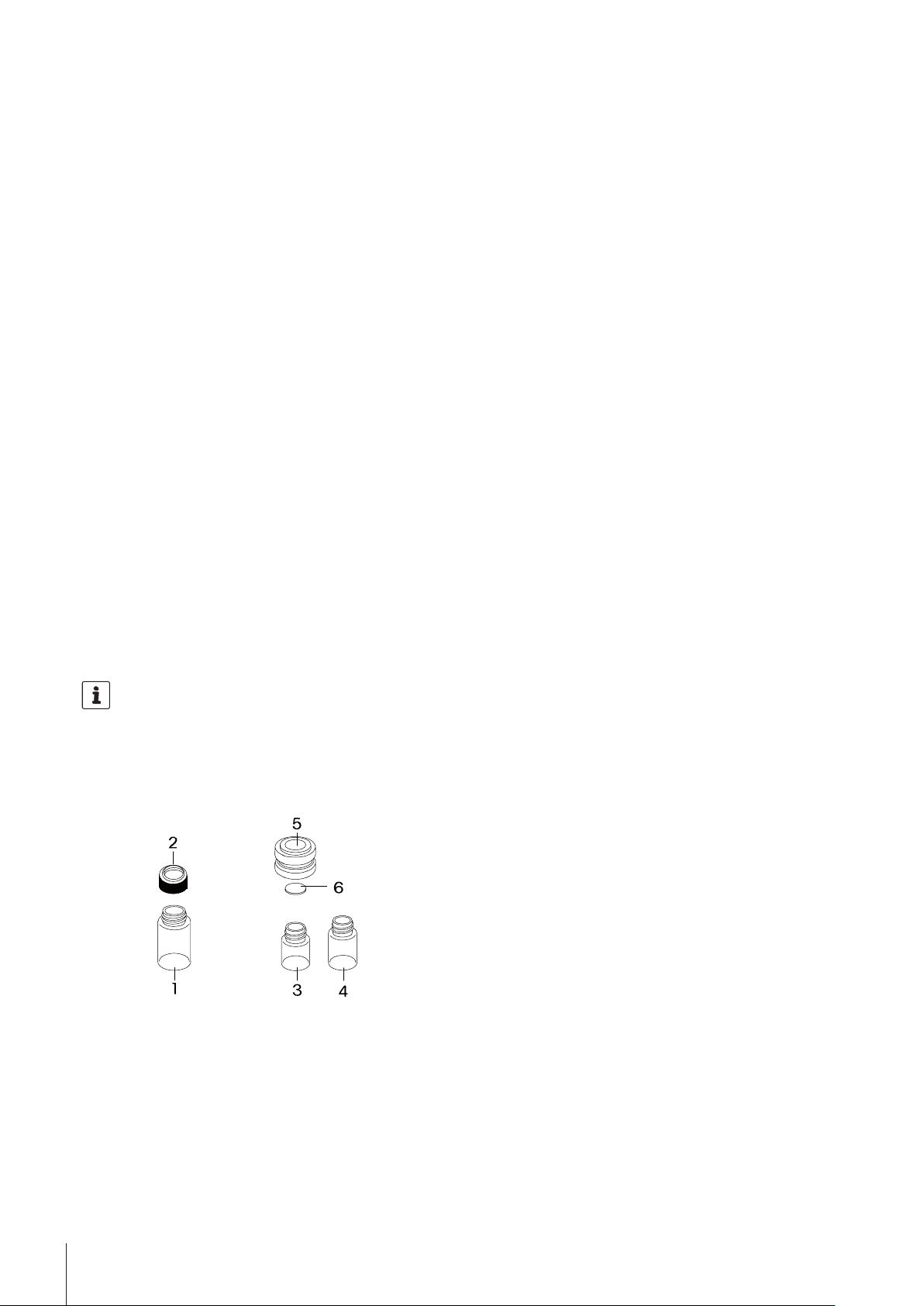
4.2Sample Vials
METTLER TOLEDO offers two different types of sample vials suitable for the SC unit Sample Delivery and Clean
ing Unit (see picture).
14 Installing SC30
Page 15

●
20 mL sample vials. These vials are available in borosilicate glass or in PP. They can be used without
cap, or they can be sealed with a cap with built-in membrane. We recommend to close the vials with a cap
for the following cases:
•
The membrane prevents the properties of the sample from changing due to evaporation or contamination
prior to the measurement.
•
The sampling nozzle is wiped off after the measurements before it moves to the rinsing pot for cleaning.
Advantage: Less time and cleaning solvent required to clean the sampling nozzle, no drops of the sample
may fall down onto the instrument when the nozzle moves from the vial to the rinsing pot.
•
The sealing of the vial during sampling is better. The sealing is done by the sampling nozzle directly on
the cap. When measuring very highly viscous samples, the time required for sampling is shorter if a
sealed vial is used.
●
6 and 9 mL sample vials. These small vials (3, 4) have to be used with an adaptor (5, order no.
51322304) and must always be sealed with a membrane (6, order no. 51322305). Before and after
measurements, these vials may be sealed with a screw cap (order no. 51322306). If you clean and dry
the system after each measurement or if you work with a Heating Option, we recommend you use this type
of vial.
To seal these types of vials, always make sure that the slits in the membrane face down (into the vial). If
this is not the case, a piece of the membrane could be cut by the sampling needle and clog the tubings!
15Installing SC30
Page 16

4.3Connecting SC unit with the Density Meter (DM)
PPU IN
PPU
PPU IN
PPU
j
Enter
Setup
Reset
Step
METTLER TOLEDO
SC30
Power Supply
SC 30 connected with the density meter (DM)
●
Place your measuring instrument to the left of the SC unit on the lab table.
●
Connect the "RS" port on the SC unit with the "Automation" port on the measuring instrument with the
RS232 cable (m). Tighten the connectors on both ports.
Connect tube (t3).
Mount the locknut at the free end of (t5), connect it to the sample nozzle (angled connector at front), and
secure the locknut.
●
Connect the tubes to the measuring cell as shown in the pictures above.
●
Mount the locknut at the free end of (t5), connect it to the sample nozzle (angled connector at front), and
secure the locknut.
●
Loosen the holder (k) for the tubes on the left side of the sampling mechanism of the SC unit.
●
Pull the relevant tubes through the tube holder and tighten the holder. Make sure that the length of the tubes
above the tube holder allows for complete free movement back and forth by the sampling nozzle!
●
Attach tube (t6) to the output of the measuring module and to the "MEAS.CELL" connection on the back of
the SC unit (see figure above "SC unit rear view").
●
Connect SC unit with the power cable (j).
16 Installing SC30
Page 17

●
PPU IN
PPU
Power Supply
j
PPU IN
PPU
Enter
Setup
Reset
Step
METTLER TOLEDO
SC30
Connect the SC unit to the power supply of the measuring instrument with the power cable. Connect the
power socket of your measuring instrument with the provided cable (n).
4.4Connecting the SC unit with the Refractometer (RM)
SC 30 connected with RM
●
Install the Refractive Index Flow Cell on the Refractometer RM (refer to the Installation Information: "Refrac
tive Index Flow Cell").
●
Place your measuring instrument to the left of the SC unit on the lab table.
17Installing SC30
Page 18

●
Connect the "RS" port on the SC unit with the "Automation" port on the measuring instrument with the
RS232 cable (m). Tighten the connectors on both ports.
Connect tube (t3).
Mount the locknut at the free end of (t5), connect it to the sample nozzle (angled connector at front), and
secure the locknut.
●
Connect the tubes to the measuring cell as shown in the pictures above.
●
Mount the locknut at the free end of (t5), connect it to the sample nozzle (angled connector at front), and
secure the locknut.
●
Loosen the holder (k) for the tubes on the left side of the sampling mechanism of the SC unit.
●
Pull the relevant tubes through the tube holder and tighten the holder. Make sure that the length of the tubes
above the tube holder allows for complete free movement back and forth by the sampling nozzle!
●
Attach tube (t6) to the output of the measuring module and to the "MEAS.CELL" connection on the back of
the SC unit (see figure above "SC unit rear view").
●
Attach tube t6 and t4 to the flow cell of the Refractometer (RM).
●
Connect SC unit with the power cable (j).
●
Connect the SC unit to the power supply of the measuring instrument with the power cable. Connect the
power socket of your measuring instrument with the provided cable (n).
18 Installing SC30
Page 19

4.5Connecting the SC unit with the Density Module (DX) combined with the
PPU IN
PPU
t8
t4
RM
DX
SC30
RM
DX
t6
t5
SC30:
“TO NOZZLE“
t4
RM in
RM out
DX in
t3
DX out
SC30:
“MEAS. CELL“
t6
Enter
Setup
Reset
Step
METTLER TOLEDO
SC30
j
PPU IN
PPU
6
t4
Power Supply
Power Supply
t3
t6
Refractometer (RM)
SC30 connected with DX combined with RM
●
Place the Density Module (DX) to the left on the Refractometer (RM).
●
Connect the the Density Module (DX) with the Refractometer (RM). For more information about connecting
the DX module to RM, refer to "DX Installation Information: Getting Started".
●
Place the measuring instruments to the left of the SC unit on the lab table.
●
Connect the "RS" port on the SC unit with the "Automation" port on the measuring instrument with the
RS232 cable (m). Tighten the connectors on both ports.
19Installing SC30
Page 20

●
Connect tube (t4).
Mount the locknut at the free end of (t5), connect it to the sample nozzle (angled connector at front), and
secure the locknut.
●
Attach tube (t3) to the output of RM and to the input of DX (low-lying connector).
●
Connect the tubes to the measuring cell as shown in the pictures above.
●
Mount the locknut at the free end of (t5), connect it to the sample nozzle (angled connector at front), and
secure the locknut.
●
Loosen the holder (k) for the tubes on the left side of the sampling mechanism of the SC unit.
●
Pull the relevant tubes through the tube holder and tighten the holder. Make sure that the length of the tubes
above the tube holder allows for complete free movement back and forth by the sampling nozzle!
●
Attach tube (t6) to the output of the measuring module and to the "MEAS.CELL" connection on the back of
the SC unit (see figure above "SC pump compartment view").
●
Connect SC unit with the power cable (j).
●
Connect the SC unit to the power supply of the measuring instrument with the power cable. Connect the
power socket of your measuring instrument with the provided cable (n).
20 Installing SC30
Page 21

PPU IN
PPU
PPU IN
PPU
j
t6
t4
Enter
Setup
Reset
Step
METTLER TOLEDO
SC30
t4
Power Supply
Power Supply
t4
t5
SC30:
“TO NOZZLE“
t4
DM in
DM out
RX in
t4
RX out
SC30:
“MEAS. CELL“
t6
RX
DM
RX
DM
SC30
SC30
4.6Connecting the SC unit with the Refractive Index Modules (RX) combined
with the Density Meter (DM)
SC30 connected with RX combined with DM
●
Install the Refractive Index Flow Cell on the Refractive Index Module (RX) (refer to the Installation Informa
tion: "Refractive Index Flow Cell").
●
Place the Refractive Index Module (RX) on the Density Meter (DM).
21Installing SC30
Page 22

The RX module can also be turned sideways to keep the total volume of the tubes as small as possible. Use the
RX fixing device ME 51337025.
●
Connect the Refractive Index Module (RX) with DM. For more information about connecting the RX module
to DM, refer to "RX Installation Information: Getting Started".
●
Connect the "RS" port on the SC unit with the "Automation" port on the measuring instrument with the
RS232 cable (m). Tighten the connectors on both ports.
●
Connect tube (t4).
Mount the locknut at the free end of (t5), connect it to the sample nozzle (angled connector at front), and
secure the locknut.
●
Attach tube (t4) to the output of DM (high-lying connector) and to the input of RX.
●
Connect the tubes to the measuring cell as shown in the pictures above.
●
Mount the locknut at the free end of (t5), connect it to the sample nozzle (angled connector at front), and
secure the locknut.
●
Loosen the holder (k) for the tubes on the left side of the sampling mechanism of the SC unit.
●
Pull the relevant tubes through the tube holder and tighten the holder. Make sure that the length of the tubes
above the tube holder allows for complete free movement back and forth by the sampling nozzle!
●
Attach tube (t6) to the output of the measuring module and to the "MEAS.CELL" connection on the back of
the SC unit (see figure above "SC pump compartment view").
●
Connect SC unit with the power cable (j).
●
Connect the SC unit to the power supply of the measuring instrument with the power cable. Connect the
power socket of your measuring instrument with the provided cable (n).
22 Installing SC30
Page 23

5Operating of the SC unit
5.1Registering the SC unit in the measuring instrument
When the measuring instrument is connected to the Sample Delivery and Cleaning Unit (SC) and the system is
switched on, the SC unit has to be registered in the measuring instrument.
In order to register the SC unit you have to perform the following steps:
1 Press Setup at your SC unit.
The Setup menu opens.
2 Press the or -keys until the entry "Interface" appears.
3 Press Enter.
"Port Mode ?" is shown.
4 Press the or -keys until "Port Mode? Unit-->" appears.
This mode is used for detecting the SC unit on the LiquiPhysics Excellence system.
Note: If your SC unit is used with an older DExx or RExx, then the Port Mode must be set to "Computer"
or "Printer".
5 Confirm with Enter.
Additionally, you have to perform the following steps in the Setup of your measuring instrument:
Navigation: Setup > Hardware > Automation
1 Tap Automation in the Hardware dialog of you measuring system to select the Sample Delivery and Clean
ing Unit (SC)
The Automation dialog opens.
2 Tap New.
The Automation parameters dialog opens.
3 Select the required SC unit in the "Type" drop-down list. Here, you also have to activate the PPU.
4 For rinsing the system, define the related solvents. These names can be selected later-on from the methods.
By default, water is preset for solvent1 and acetone for solvent 2.
5 Tap Save.
The specified SC unit appears as new type in the Automation dialog.
When the SC unit is connected to the measuring system it will be automatically detected by the measur
ing system. The "Status"= "installed" is shown.
5.2Activating additional equipment
If you want to use additional equipments such as Power Purge Unit, External Drain Valve or Limit Sensor, you
have to activate them in your measuring system as follows:
Navigation: Setup > Hardware > Automation > Automation Parameters
1 Tap Automation in the Hardware dialog.
The Automation dialog opens.
2 Select the required SC unit from the list.
The Automation parameters dialog opens.
3 Activate the required equipment.
4 Tap Save.
For more information about activating of additional equipment, refer to the Operating Instructions of your mea
surement instrument: "Setup > Hardware > Automation").
5.3Useful settings for the measuring instrument
Enter the user and country specific settings (time, date, operator names) according to the operating instructions
of the measuring instrument. If you are using the SC unit with a Density Meter, you should also enter the
23Operating of the SC unit
Page 24

atmospheric pressure of your location to ensure correct adjustment of the instrument. Set up all other peripheral
instruments (printer, barcode reader) according the Operating Instructions of your measuring instrument.
Consider the sample viscosity
In the Fill dialog (Navigation: Methods / Products > Methods > Method > Fill) and in the
Sample dialog (Navigation: Methods / Products > Methods > Method > Sample), you can
change the settings for the automatic adjustment of the sampling speed in relation to the measured sample's
viscosity. (For more information about the considering of the pump speed and viscosity, refer to the Operation
Instructions: "Methods and Products: Methods> Method Function: Fill or Sample" ).
5.4Setting up the SC unit
All settings contained in the Setup menu of the SC unit are listed below. When the SC unit is used together with
a measuring instrument, some settings are overwritten.
●
Automatic Power Switch Off
●
Sampling Speed (can only be activated, if no measuring system is connected)
●
Sampling and Draining (can only be activated, if no measuring system is connected)
●
Interface
●
Beep
●
Display Contrast
●
Serial and Version Numbers
●
Technical Service
Numbers are entered in the "Setup" menu of the SC unit with the , , , keys.
Press Setup. Select the desired menu with the and -keys. Confirm with Enter.
To leave the Setup menu, press Setup again.
Automatic Power Switch Off (Setup 00: Auto Power Off)
If you wish the measuring system (SC unit and measuring instrument connected to it)
to be automatically switched off after finishing a series of measurements, select "Yes"
for "Auto Power Off" with the -key and confirm with Enter. After leaving the "Setup"
menu, the symbol appears at the top right of the display. To disable the automatic
power switch off, select "No" and confirm with Enter.
If the Auto Power Off function is to be used, the density meter should not get its power through the SC unit but
have a separate power feed, so that it can be left running all the time.
Sampling Speed (Setup 01: Sampling Speed)
This setting is only available if the SC unit is used alone.
The samples should not be pushed into the measuring cell of the attached instrument at
too high a speed, as air bubbles may form and consequently falsify the results. The
sampling speed can be adjusted with the potentiometer (see "Layout of the Instru
ment"). This setting is usually determined with water. For sampling, the sample is
pressed into the measuring cell of the attached instrument at the set speed ("Sam
ple(Lo)"). This speed is dependent on the viscosity of the sample. At the speed set for
water, very viscous samples move very slowly or not at all. For this reason, the SC unit
is equipped with an automatic adjustment of the sampling speed to the measured sam
ple's viscosity:
If sampling is not completed by a set amount of time ("High speed after (s)", the sam
pling speed is set to the maximum. This allows the system to measure samples of dif
fering viscosities without having to change the setting of the potentiometer.
With the arrow keys enter the time (in seconds) after which the sampling speed is to be
switched from the set speed to the maximum, and confirm with Enter.
Recommended setting: 15 seconds.
If you enter "0", the sampling speed will not be changed by the SC unit.
24 Operating of the SC unit
Page 25

Sampling and Draining (Setup 02: Sequence Mode)
Drain Mod e?
Drain
This setting is only available if the SC unit is used alone.
Automatic Detection of the Sample Vials
Depending on the setting for "Stop Mode", the system either measures the number of samples you defined and
automatically skips the empty positions on the turntable, or it measures a series of consecutive samples and
stops measuring as soon as an empty position on the turntable is reached.
Select the desired setting for "Stop Mode" with the and -keys and confirm with
Enter.
●
"Set": The measuring system tries to measure the number of samples you entered.
Empty positions on the turntable are automatically skipped.
●
"Auto": The samples may be placed on the turntable one after the other starting at
any position. After Measure is pressed on the instrument, SC30 automatically
searches for the first position on the turntable which contains a vial. The measure
ments are done and the series is stopped as soon as an empty position is reached.
If "Home" was selected in the "Changer" menu of the measuring instrument, the first sample to be measured
must be placed in position 1 of the turntable.
Sampling
Because the SC unit delivers the samples to the measuring cells of the attached instruments via overpressure,
sample vials must be used that will be sealed by the sampling nozzle during sampling. The amount of time
necessary for sampling is usually controlled by the attached instrument (preset time in seconds or sample
detection by the measuring cell and automatic shutdown of the sample pump, defined in the sequence parame
ters of the measuring method).
Draining / Sample Recovery
This setting needs to be changed only if a specific manual operation from the SC display is to be launched.
Your main LiquiPhysics Excellence instrument will change this parameter automatically according to the defini
tion in the method. After measurement, the samples are either pumped into the waste container or back into the
sample vial.
Select "Drain" or "Return" with the and -keys and confirm with Enter.
●
"Drain": The samples are pumped into the waste container after measurement.
●
"Return": The samples are pumped back into the sample vials after measurement.
Interface (Setup 03: Interface)
The serial interface is used for the printout of the instrument settings or for controlling the SC unit from a com
puter.
Select "Unit", "Printer" or "Computer" with the and -keys and confirm with Enter.
●
"Unit": This setting must be chosen if the SC unit is to be used together with a
LiquiPhysics instrument (default setting from factory).
●
"Printer": The instrument settings can be printed out on a RS-P42 printer.
If you want to print out the SC units settings, connect a RS-P42 printer to the serial
interface and confirm "Printer" with Enter. Select "Print?" "Yes" with the -key and
confirm with Enter.
If you do not wish to print out the settings, select "Print?" "No" with the -key and
confirm with Enter.
●
"Computer": The SC unit can be remote controlled from a computer. If you confirm
"Computer" with Enter, you will be prompted to enter the transmission parameters
for the serial interface ("Baud Rate", "Parity", "Stop Bits" and "Data Bits"). Enter the
transmission parameters with the arrow keys and confirm each entry with Enter.
25Operating of the SC unit
Page 26

Beep (Setup 04: Beep)
Serial :
Version:
Select "Yes" or "No" with the -key and confirm with Enter.
●
"Yes": The SC unit acknowledges every keystroke, error and the end of every mea
surement with a beep.
●
"No": The beep is switched off.
Display Contrast (Setup 05: LCD Contrast)
Adjust the contrast for the display with the and -keys (0 = dark, 6 = bright) and
confirm withEnter.
Serial and Version Numbers (Setup 06: Serial/Version No.)
The instrument's serial number ("Serial") and the software version for the instrument
("Version") are displayed.
Technical Service (Setup 07: Maintenance)
The following options appear in the menu:
●
"Memory Clear": Select "Yes" with the -key and confirm with Enter if you want to return all the instrument's
settings to the default settings. If you select "No" and confirm with Enter, all your current settings remain.
●
"Keypad Check": Select "Yes" with the -key and confirm with Enter in order to test the SC unit's keypad.
The SC unit acknowledges the individual keys as follows: <Start> : 32; <Stop>: 30; <Step>: 20; <Setup>:
31; : 11; : 10; Enter: 22; : 12; : 21. To leave the keypad test, you need to switch the SC unit
off and then on again.
●
"Display Check": Select "Yes" with the -key and confirm with Enter to test the SC unit's display. To termi
nate the display test, press Stop.
●
"Sensor Check": Select "Yes" with the -key and confirm with Enter to perform a test of the sample sensor.
You are then asked to put a vial filled with a liquid (e.g. distilled water) in the turntable and to press Enter
to perform the test of the sample sensor.
●
"RS Check": Select "Yes" with the -key and confirm with Enter to test the SC unit's serial interface. To per
form this test you need an RS-232 test plug (optional). If the interface test fails, "NG" appears on the dis
play.
5.5Adjusting the measuring instrument
If you want to adjust your measuring instrument before each series of measurements, you must always place a
standard for adjustment (normally, deionized water) in front of the samples.
Start positions to choose from:
●
Home
Position number 1 on the turntable. The changer will move to position 1 for the start of a sample.
●
Current
The system will start looking for the first vial to come.
●
Absolute
The system will move to the defined position on the turntable for the start of a sample.
(For more information about turntable positions, refer to the Operation Instructions of your measuring system in
"Manual operation: Automation> Action: Rotate turntable").
5.5.1Entering an Adjustment method in the measuring instrument
Navigation: Methods / Products > Methods
It is presumed that your measuring instrument is adjusted with air and distilled water.
1 Tap New in the Methods dialog.
The Method templates dialog opens.
2 Select the ADJUSTMENT method template.
The Configuration dialog opens.
26 Operating of the SC unit
Page 27

3 Select the related SC unit in the "Automation" drop-down list..
4 Tap OK.
The ADJUSTMENT dialog opens. In this dialog you can modify the method functions.
For more information about adjusting and testing the measuring instrument, refer to the Installation Infor
mation: "Getting started").
5 You might want to insert an additional Clean function in this method before the function Fill, to ensure a
thorough cleaning and complete drying of the system also before starting the adjustment.
We suggest to enter 60seconds for "Rinse duration 1" and 20seconds for the "Rinse duration 2" parame
ter. The system is flushed with rinsing liquid 1 for 60 seconds, rinsing liquid 2 for 20 seconds and com
pletely dried before (if the "Dry" parameter is activated) before and after the adjustment.
6 Tap Save.
This method can now be started.
5.5.2Performing an adjustment
The measuring instrument should be switched on for at least 30 minutes prior to any adjustment.
The measuring instrument is adjusted as follows:
●
Place a vial with dionized water on the turntable.
●
Start your “Adjustment” method.
●
The turntable of the SC30 rotates until it finds the first vial (start position Current) and then starts the adjust
ment.
●
The adjustment of the measuring instrument is performed automatically.
●
The system is cleaned and dried (if the method was set up that way), adjusted with air and finally with
water. At the end of the procedure the system is cleaned and dried once more.
For more information about performing an adjustment, refer to the Installation Information of the Density
Meter: "Getting Started > Adjusting the Measuring Cell".
If the system could not perform the adjustment, then an error message appears on the display of the measuring
instrument. If this is the case, check the following and then repeat the adjustment:
1 Have the rinsing liquids been connected properly, i.e., is the distilled water connected to the "RINSE 1" input
and the highly volatile solvent (acetone) to the "RINSE 2" input?
2 Are all screw joints (on top of the sampling nozzle, the measuring cell's in- and output) tight?
3 Was the sample vial with the distilled water closed tightly?
4 Are the settings for the sequence in the “adjustment” method really correct?
●
The measuring instrument must be adjusted from time to time due to long-term drift of the electronics or
changes in the measuring cell (e.g., chemical corrosion).
●
Each adjustment leads to changes in the instrument settings. That means, if an adjustment is not performed
correctly, then all the following measurements will be incorrect! Therefore, we recommend that you check
your measuring instrument daily (better yet, before each sample series) with the "Cell Test" function, rather
than performing frequent adjustments. Readjust the instrument only after the instrument test has failed twice
in a row.
●
You can insert a second "Clean" function in your method, just prior to the "Fill" function. With this setting the
system is also thoroughly cleaned just prior to starting the adjustment (or test, or measurement).
●
If you have changed the measuring temperature (Navigation: Methods / Products > Methods >
Method > Measure > Cell > Meas. temperature) in your measurement method, you must
give the instrument enough time for the measuring cell temperature to completely stabilize before performing
an adjustment.
●
If you are adjusting a Density Meter at a certain temperature for the first time, you have to deactivate the
"Cell Test" parameter before performing the adjustment. After the adjustment, activate the "Cell Test" parame
ter in method.
27Operating of the SC unit
Page 28

5.6Performing the Cell Test (with air) for the Density Meter
Performing the "Cell test" method function, the instrument measures the density of the dry air in the measuring
cell after each rinse and drying cycle, and compares it to the nominal density of air at these conditions. This
means, you can check whether the density measuring cell has been contaminated. If the density measuring cell
has been contaminated, the error message "Cell Test Failed" will be displayed and printed out at the end of the
rinse and drying cycle. If this is the case, you should either increase the length of the rinsing cycle in your mea
suring methods or use a different solvent that is better at dissolving your samples.
For more information about performing a cell test refer to Installation Information: "Testing the Measuring Cell".
The maximum permissible deviation of the measured air density during the test may not exceed the tolerance
that was defined for the test. If the deviation exceeds the specified tolerance, the error message "Cell Test failed"
is displayed and printed out.
If some of your samples are rather viscous (viscosity > 10 mPa·s), you should configure your density meters
so that all adjustments are made with the viscosity correction (for more information about the viscosity correc
tion, refer to "Methods and Products> Methods> Method function> Sample" in the Operating Instructions.
●
The "Cell test" must not be used the first time the instrument is adjusted at a specific temperature.
●
The "Cell test" method function is only available for density meters.
5.7Entering a measuring method
Navigation: Methods / Products > Methods
It is presumed that your measuring instrument is adjusted with air and distilled water.
1 Tap New in the Methods dialog of your measuring instrument.
The Method templates dialog opens.
2 Select the MEASURE method template.
The Configuration dialog opens.
3 Select SC unit in the "Automation" drop-down list.
4 Tap OK.
The MEASURE dialog opens. In this dialog you can modify the method functions. (For more information
about defining measuring methods, refer to the Operating Instructions: "Methods and Products: Method
function> Measurement").
5 Tap Save.
This method can now be started.
For more information about performing a measurement refer to the Installation Information: "Getting started".
The system is cleaned and completely dried after each measurement. This is the standard workflow for measur
ing different types of samples in a row.
5.7.1Performing an Offline Cleaning
In daily routine operation it is often the case that the cleaning cycle in the measuring method is more set up for
a reasonable high throughput than for complete cleaning and drying. In such situations we recommend the fol
lowing approach:
●
Perform an offline cleaning with a cleaning method. This can be done when no samples need to be mea
sured, or in the end of the day. This method uses prolonged durations for the rinsing and drying of the sys
tem.
●
Perform a "measurement” with a dedicated solvent. The sole purpose of such a "cleaning sample” would be
to ensure a prolongued contact time inside the cell, and in the collecting vessel (S), for more in-depth
cleaning. We recommend to perform such a "measurement” approximately once a week, to avoid building
up and baking in (especially also in the collecting vessel) of sample residues over time.
5.7.2Activating Automatic Error Detection
The "Error detection" function available in the density meters (DM) and the refractometers (RM) makes it possi
ble to automatically detect the most frequent sources of errors in density and refractive index measurements.
28 Operating of the SC unit
Page 29

For more information about errors in analyses, refer to the Operating Instructions: "Analysis Sequence> Analy
sis Termination" and "Methods and Products> Methods> Method Function> Measure> Subfunction: Error
identification".
The following sources of errors are detected by this function:
●
air bubbles that found their way into the measuring cell or developed during the measurement,
●
air bubbles that found their way into the measuring cell or developed during the measurement,
●
residues of solvent in the measuring cell,
●
solid particles in the sample (e.g., dust),
●
inhomogeneous sample
The "Error detection" function effects multiple measurements of each sample. The mean and the standard devia
tion of the individual results are automatically calculated. The "Error detection" function works as follows:
The sample is pushed into the measuring cell, the measurement is performed and the result (density and/or
refractive index) is stored. Afterwards, the sample pump is reactivated for a short period of time in order to
move the sample forwards. Another measurement is performed and the result is stored. This last step is repeat
ed several times. At the end, the instrument calculates the mean and the standard deviation of the individual
measurements.
1 Tap the "Measure" method function in the MEASURE dialog.
(Navigation: Methods / Products > Methods > MEASURE
The "Measure" dialog opens.
2 Tap the "Error detection" button.
The "Error detection" diaog opens, where you can activate "Bubble Check" and "Multiple measurement"
(refer to Methods and Products: "Measure” > Subfunction Error information in the DM or RM Operating
Instruction)
If you want to activate the "Multiple measurement" you have to enter the number of measurements, the
refill ratio and the maximum standard deviation (Max. SD).
Note: The value for "Max. SD" must to be selected in agreement with the homogeneity of the measured
samples (lower for homogenous samples, higher for inhomogeneous samples). However, the value for
"Max. SD" should not be lower than twice the resolution of the measuring instrument.
3 Confirm with OK and save your entries.
You can start your method now.
5.7.3Setting the Sampling Speed
The samples should not be pushed into the measuring cell of the attached measuring instrument too quickly,
as air bubbles may form and falsify the measured values. The sampling speed must be set in such a way that
a thin fluid (e.g., water) reaches the measuring instrument's measuring cell within 3 seconds of sample pump
activation. If viscous samples are measured, the sampling speed will automatically be reduced by the viscosity
of the sample.
This reduced sampling speed can be set at the potentiomenter (K) (refer to drawing in section "Layout of the
Instrument> The Instrument"). For normal non-viscous samples (e.g. water or edible oil) the turning knob is
set to the beginning of the solid bar marking approximately.
For more information about the setting the sampling speed, refer to the Operating Instructions of your measuring
instrument: "Methods and Products> Method function> Fill"
5.8Running a pre-defined sample series
The sample data (numbers and names of the samples, measuring method and viscosity correction) are entered
in the measuring instrument before the series is started.
In the example given below it is presumed that you measure three samples (for more information about how to
perform a measurement (incl. setup settings, cleaning -, adjusting and testing the measuring cell), refer to the
Installation Information of your measuring system: "Getting Started").
29Operating of the SC unit
Page 30

Make sure that the correct measuring method has been selected Select the appropriate method (Navigation:
Methods / Products > Methods > Method). For more information about defining series, refer to
the Operation Instruction: "Series".
5.8.1Defining series
1 Select Series (Navigation: Home > Series)
The Series list dialog opens.
2 Tap New.
3 Enter the series ID in the related data field and save your entry.
The Series dialog opens. Here you can insert a new method or you can change the parameters for a
listed method you want to assign to.
4 You can assign a method to the series in "Method ID" list box.
5 You can enter the sample ID in the related data field.
If you use a barcode reader scan in the sample identification barcodes of the three samples, one after the
other. If no barcode reader is available, enter the sample IDs using the keypad
6 Tap OK and save your new series.
The Start button is available.
7 Tap Start.
The Start analysis dialog opens (for more information about the Start analysis dialog, refer to your
measurement instrument's Operating Instruction, section "Analysis sequence").
Here you can define the SC30 start position before you start the series or the items (sample ID and the
correction factor for the method which will be applied) or define the position of the samples on the
turntable (refer to the Operating Instructions: "Manual operation: Automation > Action: Rotate turntable")
8 Determine the "SC30 start position" at the turntable in the Start analysis dialog. The following positions can
be determined:
"Home": Position 1
"Absolute position": You can enter a specific position.
"Current position": the turntable moves to the next sample, regardless of its position.
By default the "Current position" is used.
9 Fill three sample vials to about 80% with the samples you want to measure.
10 Close the sample vials and place them on the turntable.
If you have selected "Home" for "Start Position", you must place the first sample in position 1 of the
turntable.
If you select "Current position", however, you may leave one or more positions on the turntable empty
between the samples.
11 When starting a measurement method or a product from the editor, homescreen or via shortcut , you can
select the option "Continous run". If this parameter is activated, the vials are sequentially processed until an
empty space is found on the sample changer.
5.8.2Using viscosity correction
If you are performing density determinations of viscous samples select the viscosity correction for the corre
sponding samples (this parameter is available in the method function "Sample: Navigation: Home >
Methods / Products > Methods):
1 For viscous samples you can activate the "Viscosity correction" (Navigation: Methods / Products >
Methods > Method > Sample).
You can select a visosity < 2000mPa*s (normal selection), or > 2000mPa*s (only for very highly vis
cous samples – this will always apply a maximum correction to the sample density, even if the sample has
no viscosity at all!).
Note: If you want to measure very highly viscous samples with a viscosity greater than 10'000 mPa·s, you
can enter a value in the "Viscosity value" data field.
2 Confirm with OK and save the method.
3 Enter the Series ID in the Series item dialog (refer to the Operating Instruction: "Series"). The sample ID
receives postfix "-01", where the number is incremented.
30 Operating of the SC unit
Page 31

4 Tap Start in the Start analysis dialog.
5.8.3Performing a instrument test with a known liquid standard
If you want to check the cell, the measuring system performs an instrument test at the corresponding positions
instead of a normal measurement. You may thus place a vial with a know standard (e.g. distilled water at
around room temperature) at the beginning of each sample series on the turntable. The system then performs
an instrument test before the samples are measured. If this test fails, the series is interrupted automatically.
Your samples are thus only measured if the system is working correctly.
5.8.4Using error detection
If you have activated automatic error detection (Navigation: Methods / Products > Methods >
Method > Measure), a multiple measurement of each sample will be performed. After each measurement,
the system will be cleaned and dried according to the settings in the method. For more information about error
detection, refer to the measuring instrument's Operating Instruction: "Methods and Products: Methods> Method
Function> Measure> Subfunction Error identification".
After an error message appears, then please check the following:
●
Are all tube connections tight?
●
Are there any air bubbles or solid particles (e.g., dust) in your samples?
●
Is the liquid used in the "Rinse-1" cycle really able to dissolve the measured samples completely? If you are
measuring mainly aqueous products but some among them contain oils, fats or proteins, you cannot use
pure water as first rinsing liquid. In such cases we recommend you use water containing 0.2 to 0.5 % (2 5 ml per liter) of deconex 12 NS (ME 51322309) as the first rinsing liquid.
●
Is the liquid used in the "Rinse-2" cycle really highly volatile (e.g., could the solvent contain a lot of water)?
●
Are the measuring cells sufficiently cleaned in the sequence of this method, or (if you are measuring similar
samples without cleaning the cell entirely after each measurement) is the over-sampling rate large enough.
31Operating of the SC unit
Page 32

6Care and Maintenance
6.1Daily Performance Check
Test your measuring system at regular intervals:
Measuring Instrument
Verify the condition of the instrument and the precision of the system regularly with a "Test" method (refer to the
measuring instrument's Installation Information: Getting started> Testing the Measuring Cell).
Refractive Index Measuring Cell (if present)
Periodically dismantle the flow cell unit of the refractive index measuring cell and clean the prism's surface with
a soft tissue paper and an appropriate solvent.
Desiccator
The silica gel in the desiccator must be replaced or re-activated (i.e., dried in an oven) when its color has gone
from orange (dry) to pink (damp). If this is not done, the system cannot be completely dried and thus, a cor
rect adjustment of the density measuring cell with air is no longer possible!
This is especially important in high relative humidity surroundings, and when measuring at low temperatures
(below room temperature).
Tube Connections
The tube connections can become loose over time. Check them periodically for tightness and tighten them if
necessary.
Sampling Nozzle
Sampling nozzle
If the sampling nozzle leaks liquid at the top, or if you frequently have air bubbles in the tube above the sam
pling nozzle, you may have to replace the teflon seal in the screw joint at the top of the sampling nozzle
If sampling takes very long, or if solvent is coming out at the top of the rinsing pot during the rinsing cycle, then
the perfluoroelastomer cap at the sampling nozzle needs to be replaced.
If liquid is seeping out at the fastening mechanism at the top of the sampling nozzle (t), then the O-ring (u,)
needs to be replaced. Call MT service to do this, or proceed as follows:
- dismantle the sampling nozzle,
- loosen the screws take the sampling nozzle out and exchange the O-ring.
When reassembling the sampling nozzle, make sure that the length of the needle is set correctly: Press the
sampling nozzle into the rinsing pot and adjust the length so that it nearly touches the bottom of the rinsing pot.
32 Care and Maintenance
Page 33

Air Filter
To guarantee proper cooling of the electronics, the air filters need to be taken out and cleaned or replaced at
regular intervals. The air filters are only clipped onto the fans, do not remove the screws of the fan!
Peristaltic Pump
Make sure the tube of the peristaltic pump is not worn out. If this should be the case, remove the head of the
peristaltic pump by turning it counterclockwise and lifting it up, remove the tube connections on the head and
replace the complete head with a new one.
Screw Joints of the Density Measuring Cell
If air bubbles frequently enter the measuring cell, the cell connectors of the density measuring cell need to be
tightened slightly or replaced.
6.2Periodic Performance Check
Check at fixed time intervals (one month after installing the system and later on at least every three months)
whether the internal tube connections of the SC unit are still tight. To do this, proceed as follows:
1 Turn the SC unit off.
2 Remove all tube connections (waste tube, rinsing liquids, etc.) on the rear side of the SC unit.
3 Remove the four screws of the compartment containing all the valves and the diaphragm pump (see draw
ing above).
4 Slide the compartment out of the SC unit.
5 Check all the internal tube connections by turning all the white plastic screws clockwise (by hand, do not
use any tools!).
6 Slide the compartment carefully into the SC unit, mount the four screws and reconnect the external tube con
nections.
6.3Adjusting the Sampling Mechanism
Adjusting the Length of the Sampling Nozzle
When the SC unit leaves the factory, the sampling nozzle is not set to its maximum length, to be used with a
standard 20 mL vial without a cap. If required, adapt the length of the sampling nozzle as follows:
1 Remove the cover of the SC unit's sampling mechanism.
2 Put a vial into the holder (Rinse 2).
3 Press the -key on the SC unit. The sampling nozzle moves on top of the vial. When the motor stops,
press the Stop immediately (important!).
33Care and Maintenance
Page 34

4 Loosen the three screws (y) on the sampling nozzle.
Y
Y
5 If the sampling nozzle is too short (i.e. if its point is far away from the bottom of the vial) proceed as fol
lows:
- Hold the needle at its top and push it down into the vial until its point is located approximately 1.5 mm
above the bottom of the vial.
- Hold the needle and tighten the three screws.
6 If the sampling nozzle is too long (i.e. its point touches the bottom of the vial) proceed as follows:
- Press Enter and the -key on the automation unit simultaneously.
- Press Reset on the automation unit when the point of the needle is located approximately 1.5 mm above
the bottom of the vial.
- Press the part with the three screws tightly down onto the adapter and tighten the three screws of the sam
pling nozzle!
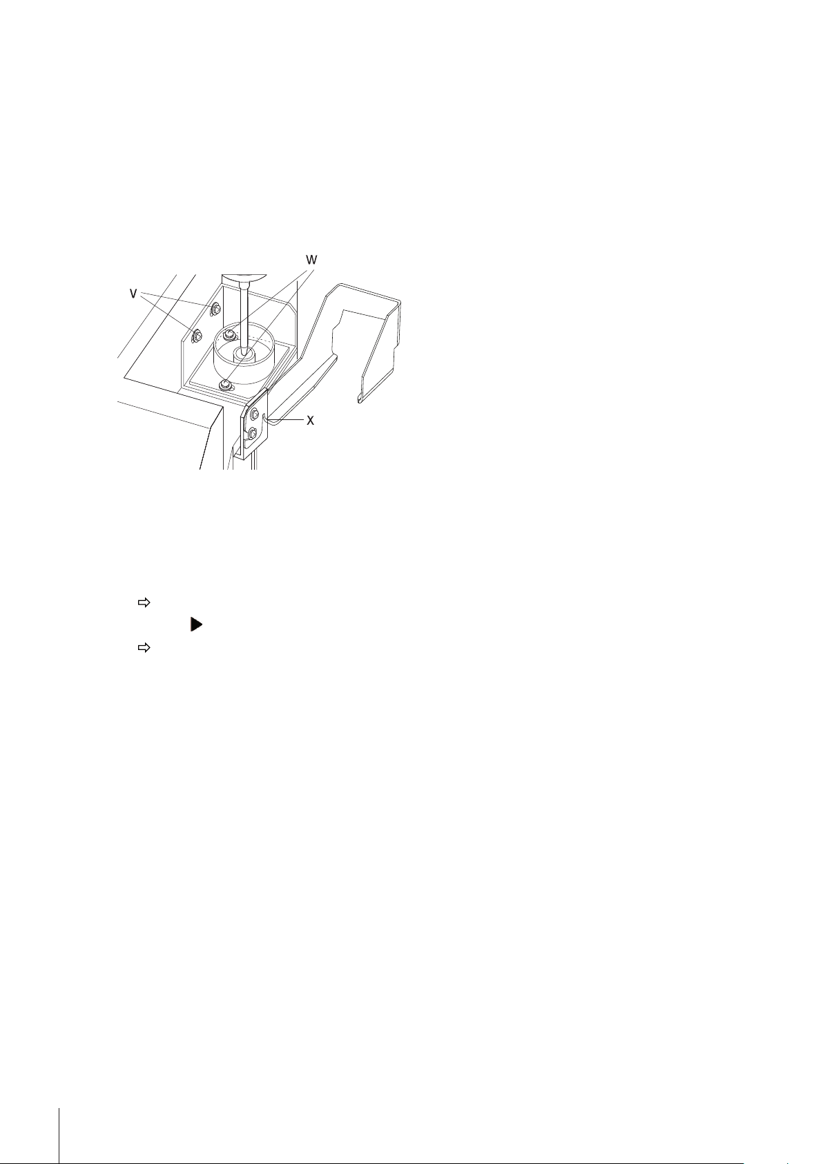
Rinsing Pot
The rinsing pot is attached to the SC unit with 2 screws (v). To move the rinsing pot forwards or backwards,
loosen both screws and push the rinsing pot into the desired position, then tighten the screws again. To move
the rinsing pot sideways, loosen the screws (w), push the rinsing pot into the desired position and tighten the
screws again.
34 Care and Maintenance
Page 35

7Disposal
In compliance with European Directive 2002/96/EC on Waste Electrical and Electronic
Equipment (WEEE), this instrument must not be disposed of together with domestic
waste. This also applies to countries outside the EU, per their specific requirements.
Please dispose of this product in accordance with local regulations at the collecting
point specified for electrical and electronic equipment.
If you have any questions, please contact the responsible authority or the distributor
from which you purchased this instrument.
Should this instrument be passed on to other parties (for private or professional use),
the content of this regulation must also be related.
Thank you for your contribution to environmental protection.
35Disposal
Page 36

8Error Messages and Malfunctions
The following error messages may appear on the measuring instrument's display:
Error message Cause Action
Nozzle Error!
Remove the interfer
ence
Connect Error!
Check connect
cable.
Table error
Remove the interfer
ence
The error messages below may appear on the SC unit's display:
Error message Cause Action
Nozzle Error! The SC unit's sampling nozzle is blocked. Remove obstacle.
Nozzle Timeout A movement of the sampling nozzle lasts
Table error The SC unit's turntable is not installed cor
Table Timeout The SC unit's turntable is blocked Press Reset on the SC unit and remove the
Table Not Found The SC unit's turntable is not installed cor
The SC unit's sampling nozzle is blocked. Remove obstacle.
Communication from measuring Instru
ment to the SC unit is not working properly.
Attach the connecting cable (m) properly
or replace it. Make sure that the selection
of the SC unit has been configured correct
ly on the measuring instrument.
The SC unit's turntable is not installed cor
rectly..
Move the turntable slightly by hand so that
it lies flat on the SC unit. Press Step on the
SC unit.
Press Reset on the SC unit and remove the
longer than 30 seconds.
obstacle.
Press Reset on the SC unit. Press the rectly..
key and then Step in order to move the
sampling nozzle into the drain pot and to
turn the turntable one position forwards.
obstacle.
Install the turntable correctly.
rectly.
If the error message "Out" (automatic error detection activated) appears frequently on the measuring instru
ment's display, please check the following:
●
Have your samples been properly degassed? If your measuring temperature is above ambient temperature,
you should degas your samples (e.g., in an ultrasonic bath) at a temperature above the measuring temper
ature.
●
Do your samples contain solid particles (e.g., dust) or are they inhomogeneous? If necessary, enter a high
er value for the "SD Limit".
●
Is the liquid used in the "Rinse-1" cycle really able to dissolve the measured samples completely? If you are
measuring mainly aqueous products but some among them contain oils, fats or proteins, you cannot use
pure water as first rinsing liquid. In such cases we recommend you use water containing 0.2 to 0.5 % (2 5 ml per liter) of deconex 12 NS (ME 51322309) as the first rinsing liquid and enter a time of at least 10 s
for "Rinse-2".
●
Are all tube connections tight? Tighten the tube connections by hand, if necessary.
●
Are the cell connectors of the density measuring cell tight? Tighten the cell connectors and screw joints by
hand, if necessary. Beware: The cell connectors are made of Teflon. Teflon is a soft material that deforms
(flows) permanently under pressure. The cell connectors should not be too tight or they will deform and
begin to leak!
●
Do large quantities of rinsing liquids remain in the measuring cells after cleaning? If necessary, adapt the
parameters in the sequence of your methods, work with different rinsing liquids or use a Power Purge Unit.
36 Error Messages and Malfunctions
Page 37

9Technical Specifications
SC30 Sample Delivery and Cleaning Unit
Sampling and cleaning
Turntable for 30 samples (20 mL vials, standard; 6 or 9 mL vials with
adapter, option)
Sampling by means of overpressure, speed adjustable maximum viscosity
of sample: 30'000 mPa·s minimum amount of sample: approx.
3 mL
Duration of sampling
1000 mPa·s
10'000 mPa·s
30'000 mPa·s
Draining / Purging with air
Rinsing with up to 2 rinsing liquids, adding air to the rinsing liquids
Display LCD (liquid crystal display), 2 lines, backlit
Ports 1 RS-232C for the measuring instrument
Power source AC 100 - 120 V / 200 - 240 V; 50/60 Hz
Ambient conditions temperature: 5 - 35°C
Materials (in contact with sample)
with a Density Meter borosilicate glass, PTFE (polytetrafluoroethylene), stainless steel
with an Refractometer
Power consumption 760 W max.
Dimensions 582 mm (W) x 392 mm (D) x 402 mm (H)
Weight 17 kg
approx. 25 seconds
approx. 160 seconds
approx. 990 seconds
(mechanical cleaning)
humidity: < 85 % RH (no condensation)
SUS304 (or Hastelloy C22)
sapphire, perfluoroelastomer and stainless steel SUS316, PTFE
(polytetrafluoroethylene), stainless steel SUS304 (sampling nee
dle)
37Technical Specifications
Page 38

10Standard Equipment
Enter
Setup
Reset
Step
METTLER TOLEDO
SC30
SC30
Enter
Setup
Reset
Step
METTLER TOLEDO
SC30
Sample Delivery and Cleaning Unit
Operating Instructions
1 SC30 Sample Delivery and Cleaning Unit SC30
1 Operating Instructions 51710903
1 Turntable for 30 samples 51327301
1 Power cable according to your
order
1 Connecting cable (for old generation DExx and DRxx) 105010
1 Connecting cable (RS-232C, 2 x 9 pin female) for
51190362
LiquiPhysics Excellence instruments
1 Connecting tube [t5] 51327329
1 Teflon seal ( c ) see optional equip
ment
2 Locknuts ( d, e ) 51322297
2 Connecting tubes [t1, t2] see optional equip
ment
38 Standard Equipment
1 Connecting tube [t3]
(M8 / M8 / L400 mm)
51337226
Page 39

1 Waste tube [t10] 51327327
1 Connecting tube [t6] 51324644
1 Protective cover [B] 51327303
1 Set:
51327330
- Table support
- Protective Cover (metal)
2 Filters for rinsing liquids 51328137
2 Bottles for rinsing liquids see optional equip
ment
1 Holder for bottles -
1 Desiccator tower 51337180
●
2 Bags silica gel (170 g each) see optional equip
ment
1 Air filter see optional equip
1 Allen wrench (M 2.5) -
1 Package of sample vials (glass, 20 mL, 148 pcs.) 51322310
Screw caps with seal (148 pcs.) 51322319
●
Starting Kit Small Sample Vials (includes 1 adapter, 5x 9mL vials, 1x 6mL vial,
10 septa, 6 screw caps, 1 mounting rod, instruction sheet)
ment
51322307
39Standard Equipment
Page 40

10.1Connection tubes
No. in Manual In standard delivery Spare part order number Tube
Tube Reference num
ber
t1 985210036 100 51322243 150 4
t2 985210036 100 51322243 150 4
t3 12002300148 50 51337226
t4 984340102 80 51322234 80 5
t5 (SC1) 984340316 110 51327329 120 3
t5 (SC30) 984340317 85 51327329 120 3
t6 984340238 80 51324644 120 3 (M)
t7 (attached) - not used - t8
t9
t10 985210050 200 51327327 150 1
t11=t6 984340238 80 51324644 120 3 (M)
t12 12002300048 35 51337226 40 5 (M)
t21 (attached) - 51322243 150 4
t22 (=t11a) 985210068 30 (M8) 51337223 40 2 (M)
t13 - - 51322243
(attached) 15 (SC1)
Length [cm] ME order
number
51337227
not used
36 (SC30)
+ 51322263
Length [cm] Type
40
55
51328032(30)
or
51328133(100)
150
screw + insert
5 (M)
5 (M)
-
4
Tube types
Type Connection 1 Tube Connection 2
1 none none
2 none
2 M none
3
3M
4 none none
5
5M
syringe adapter/
51337158
40 Standard Equipment
Page 41

11Optional Accessories
1 Head for peristaltic pump (complete) with small tube
(standard version ) [A]
1 Head for peristaltic pump (complete) with big tube
(faster pumping speed, for highly viscous samples)
1 Cap for sampling nozzle (black perfluoroelastomer) [w]
(including 2 discs of EP)
1 Packing silicone (5 pcs. white) to be used with51327326 51327435
1 Sampling needle made of Hastelloy C22
(to measure highly aggressive samples)
1 Standard sampling needle (stainless steel coated)
1 Package of Teflon seals (5 pcs.) [c] 51322203
51327324
51327325
51327326
51327420
51327430
1 Tube nozzle for density cell 51337158
1 Connecting tube 51322243
1 Connecting tube (M8/ M8, L= 550mm) 51337227
1 Connecting tube (M8/ M8, L400mm) 51337226
Standard vials 20 mL
- 1 Package of glass vials (20 mL, 148 pcs.)
- 210 Packages of glass vials (20 mL, 148 pcs each),
210*148pcs.
- 1 Package of plastic vials (PP, 20 mL, 148 pcs)
- Box with 1400 plastic vials (PP, 20 mL)
- Screw caps with seal (148 pcs, for 20 mL vials)
- Screw caps with seal (jumbo pack: 31'000 pcs.)
51322310
51327397
51322360
51322361
51322319
51322351
41Optional Accessories
Page 42

Small vials
- 9 mL sample vials (borosilicate glass, amber),
10 * 186 pcs.
- 6 mL sample vials (borosilicate glass),
10 * 186 pcs.
These small vials may only be used together with adapter
51322304 plus seal 51322305
51322312
51322313
1 Package of adapters for small sample vials (30 pcs. glass
51322304
fiber strengthened PTFE)
required for the 6 and 9 mL vials
1 Package of seals for small sample vials, 2'000 pcs. must
51322305
be used in adapter 51322304
1 Package of screw caps for small sample vials, 3'500 pcs.
51322306
polypropylene,
suitable for the 6 and 9 mL vials
1 Rod to insert the seals into the adapter and to push them out 51322308
1 Desiccator tower 51337180
●
1 Silica gel bag (170 g) 51337241
1 Bottle of deconex 12 NS (1.3 kg)
51322309
Concentrate for rinsing liquid 1 (aqueous)
1 Bottle for rinsing liquids [N, O] 51328127
1 Package of air filters (5 pcs.) 51326102
1 Power Purge Unit, including:
- 1 Connecting tube [t1, t2]
- 1 Screw connect
51327365
51322243
51322263
1 Blind plug (PPU connector) 51327380
Support for DM or RM 51337089
42 Optional Accessories
Page 43

1 Compartment containing all valves and diaphragm pump 51327328
1 Refractive Index Flow Cell complete required to connect an
RM refractometer to the SC1
External drain valve (pinch tube valve)
(required for the measurement of samples which contain par
ticulate material with a diameter > 0.4 mm). May not be used
together with a heating option! Tube not resistant against alde
hydes and ketones (e.g. acetone)!
51337024
51327346
43Optional Accessories
Page 44

Page 45

Page 46

Page 47

Page 48

Mettler-Toledo AG, Analytical
CH-8603 Schwerzenbach, Switzerland
Tel. +41 (0)44 806 77 11
Fax +41 (0)44 806 73 50
www.mt.com
www.mt.com
For more information
Subject to technical changes.
© Mettler-Toledo AG 03/2011
51710903
*51710903*
 Loading...