

Page 1
Refractometers
RM40 / RM50
Operating Instructions
Page 2

Page 3

Table of Contents
Introduction1 7
Description of the Refractometer2 8
Principles of Refractometry3 10
Description of Functions4 12
Setup5 15
Definition of the Refractive Index3.1 10
Method of Measurement3.2 10
Design of Measuring Cell3.3 10
Layout of the Terminal4.1 12
Operating the Touchscreen4.2 12
Homescreen4.3 12
The User Interface4.4 13
Entering Data in the User Interface.4.4.1 13
Shortcuts4.4.2 14
Adjustments & Tests5.1 15
Adjustment Sets5.1.1 16
Test Sets5.1.2 16
Hardware5.2 16
Cell5.2.1 17
Automation5.2.2 17
External Instruments5.2.3 19
Peripherals5.2.4 20
Sensors5.2.5 23
Auxiliary instruments5.2.6 24
User settings5.3 25
Language5.3.1 25
Screen5.3.2 25
Beep5.3.3 25
Shortcuts5.3.4 26
Keyboards5.3.5 26
Global Settings5.4 26
System5.4.1 26
User Management5.4.2 26
Users5.4.2.1 27
Account Policy5.4.2.2 27
User Groups5.4.2.3 27
Analysis and Resources Behavior5.4.3 28
Physical Properties5.4.4 29
Tables & Values5.5 29
Tables5.5.1 30
Auxiliary Values5.5.2 31
Maintenance & Service5.6 31
MT Service5.6.1 31
Import / Export5.6.2 32
Add External Cell5.6.3 33
Reset to Factory Settings5.6.4 33
Firmware5.6.5 33
Update5.6.6 33
Hardware / Firmware summary5.6.7 34
Board Tests5.6.8 34
Table of Contents 3
Page 4

Cell5.6.9 34
Export Adjustments / Tests / Measurements5.6.10 35
Methods and Products6 36
Methods6.1 36
Establishing Methods6.1.1 36
Creating a Method Copy6.1.2 38
Modifying or Deleting Methods6.1.3 38
Method Syntax6.1.4 38
Standard Data6.1.5 40
Condition6.1.6 40
Method Function6.1.7 41
Title6.1.7.1 42
Configuration6.1.7.2 42
Sample6.1.7.3 42
Fill6.1.7.4 44
Measure6.1.7.5 45
Calculation6.1.7.6 47
Clean6.1.7.7 48
Online Display6.1.7.8 50
Report6.1.7.9 50
Cell Test6.1.7.10 51
Temperature Compensation6.1.7.11 51
Adjustment6.1.7.12 52
Test6.1.7.13 52
Instruction6.1.7.14 52
Auxiliary Value6.1.7.15 52
Wait6.1.7.16 53
Auxiliary instrument6.1.7.17 53
PowerShower6.1.7.18 54
Stir6.1.7.19 55
Line rinse6.1.7.20 56
Park6.1.7.21 56
Products6.2 56
Create Products6.2.1 57
Linking Methods with Products6.2.2 57
Parameters for Products6.2.3 57
Calculations in Products6.2.4 59
Series7 60
Delete Series7.1 61
Creating a series copy7.2 61
Results and Statistics8 62
Statistics8.1 63
Information8.2 63
Data8.3 63
Manual Operation9 65
Automation9.1 65
Action: Dry9.1.1 65
Action: Rinse9.1.2 65
Action: Pump sample9.1.3 66
Action: Move to position9.1.4 66
Table of Contents4
Page 5

Cell9.2 66
Action: Cell conditioning9.2.1 67
Cell Test9.2.2 67
Analysis Sequence10 68
Starting an Analysis10.1 68
Start from Editor (Methods/Products/Series)10.2 69
Start from Homescreen10.3 69
Start via Shortcuts10.4 69
Start with Barcode Reader10.5 69
Start with Handheld Reader10.5.1 70
Start with Built-in Barcode Reader10.5.2 70
Start with ErgoSens10.5.3 70
Continuous run10.6 71
Analysis Termination10.7 71
Errors in the Analysis Sequences10.8 71
Malfunction Types: Error10.8.1 71
Malfunction Types: Terminate error10.8.2 71
Malfunction Types: Critical error10.8.3 72
Tasks and Online Screen11 73
Tasks11.1 73
"Tasks" Button11.1.1 73
Online Screen11.2 73
Method type: Measurement11.2.1 73
Method Type: Adjustment11.2.2 74
Method Type: Test11.2.3 74
Method Type: Clean11.2.4 74
Appendix12 75
Raw Data12.1 75
Result proposals12.2 76
Refractive Index for Water12.3 78
Density12.4 78
Critical errors12.5 80
Index 82
Table of Contents 5
Page 6

Page 7

1Introduction
Simple and compact
The METTLER TOLEDO RM40/RM50 refractometers are modern, compact instruments suitable for use in a vast
diversity of application areas. They can be used, for example, in quality control as well as in research and
development and meet the most demanding requirements.
These compact refractometers perfectly combine simple, easy-to-understand operation with an extremely high
level of measuring accuracy and outstanding reliability. With their plug & play capability, they automatically
detect external devices and sensors.
These refractometers can be operated as standalone instruments or run from a computer using the LabX PC
software. Straightforward user guidance on the large color touchscreen enables intuitive operation. User-defin
able shortcuts allow all functions to be activated directly from the home screen with a single click.
Touchscreen control of the instrument and the method function parameters are described in the Operating
Instructions. The Installation Instructions explain all the necessary steps for setting up your instrument. You are
then guided through the first refractive index measuring process with the aid of a practical example.
If you have any additional questions, METTLER TOLEDO is always available to assist you.
7Introduction
Page 8

2Description of the Refractometer
The RM40 / RM50 refractometers measure the refractive index nD of liquids. The two instruments differ in mea
suring precision. Both instruments:
●
measure liquids whose refractive indices range respectively from 1.3200 to 1.7000 (RM40) and to
1.58000 (RM50).
●
require only minimal sample quantities for measurements (0.5 mL),
●
maintain the temperature of the sample constant with the aid of a built-in Peltier thermostat in a range from
5 to 100°C (RM40) and 5 to 75°C (RM40).
●
directly indicate the sugar content of samples in various sugar units (Brix, invert sugar, HFCS42 or
HFCS55)
●
calculate the concentration of a solution by means of data from measured standard solutions, literature
tables or formulas
●
are equipped with an integrated test function that enables regular testing of the accuracy of the measure
ment,
●
enable checking of the product-related specification limits and generate rolling statistics.
The samples can be introduced manually with a syringe. For the optimal use of the RM refractometers, the fol
lowing pumps and sample changers are available:
●
A peristaltic pump (FillPal):
For the automatic filling, emptying and rinsing of the cell.
●
The autosampler InMotion™
The autosampler for a completely automatic measurement of up to 303 aqueous, low viscous samples in
series.
●
The automatic sample and cleaning unit (SC1):
for fully automated measurements of free-flowing and viscous samples. The system automatically cleans
and dries itself on completion of a measurement so that it is ready for the next measurement.
●
The sample changer (SC30):
The SC30 sample changer for the completely automatic measurement of up to 30 samples in series.
The following devices can be connected:
●
Computer for operation under LabX
●
External measuring cells:
•
METTLER TOLEDO DX40, DX45 or DX50 density - modules
•
METTLER TOLEDO RX40 or RX50 refractive index - modules
●
Barcode reader for scanning sample data, set values of certified standards and for starting measurements
●
finger print reader for user identification
●
Compact printer (USB-P25), to print out results
●
External instruments:
•
METTLER TOLEDO S20 – SevenEasy™ pH
•
METTLER TOLEDO S30 – SevenEasy™ Conductivity
•
METTLER TOLEDO S220 - SevenCompact™ pH/Ion
•
METTLER TOLEDO S230 - SevenCompact™ Conductivity
•
Lovibond colorimeters PFX880/ PFXi880, PFX950/ PFXi950 and PFX995/ PFXi995 series, Tintometer
•
Minolta colorimeters CM-5 / CR-5
●
USB stick
●
External sensors:
•
ErgoSens – Infrared movement sensor for the automatic start of measurements
•
LevelSens – Level sensor for waste bottle
•
AtmoSens – Air pressure sensor for measuring air pressure and taking the latter into account in adjust
ments and tests with air.
Special features of the refractometer:
8 Description of the Refractometer
Page 9

●
A maintenance-free LED is used as a light source for the measurements.
●
The measuring prism is made of sapphire. It is therefore extremely corrosion resistance and very robust. It
also has a high thermal conductivity.
●
For temperature measurement, NTC thermistors with extreme long-term stability are used. This means that
there is no need to regularly readjust the measuring cell.
9Description of the Refractometer
Page 10
3Principles of Refractometry
n
1
n
2
n
1
β
n
2
α
sin
sin
=
1
2
β
β
1
2
3
4
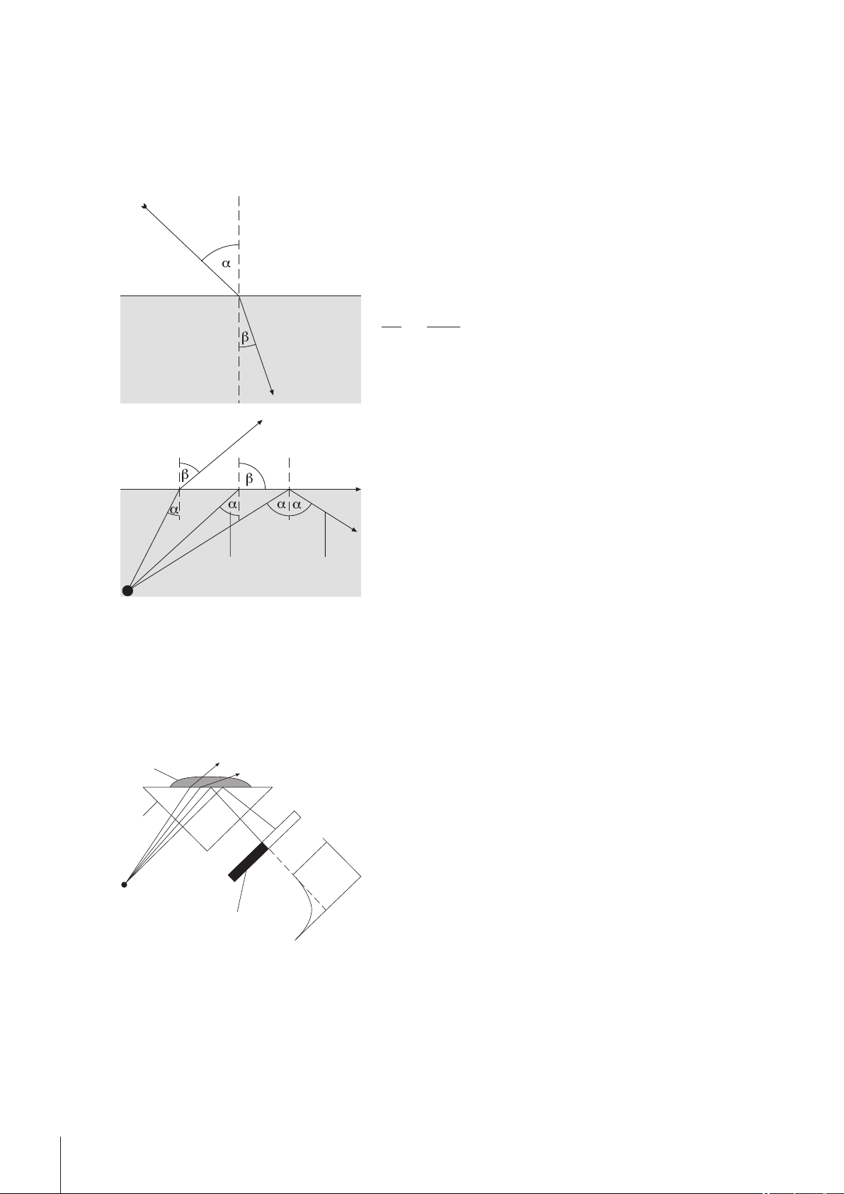
3.1Definition of the Refractive Index
The refractive index of a substance is the ratio of the speed of a light beam in a vacuum to its speed in the sub
stance (dimensionless).
If a light beam crosses at a certain angle from an optically less
dense to an optically denser medium (e.g. from air to water), it
is deflected; when the beam crosses from one medium to
another perpendicularly no directional change takes place.
According to Snell's law, the ratio of the refractive index of the
two media is proportional to the ratio of the incident and refrac
tive angle of the light beam:
If a light beam passes from an optically denser to a less dense
medium, it is also deflected. If the angle of incidence α is
increased, then it reaches a critical value, at which the light
beam no longer enters the less dense medium (refractive angle
= 90°). When this "critical angle" is exceeded, total internal
reflection occurs. The refractive index is calculated from this
critical angle α :
As refraction depends on the wavelength of the incident light, the refractive index n is measured as standard
with the D line of sodium (wavelength 589.3 nm) and designated nD.
The refractive index not only depends on the wavelength of the light but also on the temperature of the mea
sured sample. For this reason the temperature must always be stated along with the result, e.g. n
The standard temperature is 20 °C.
3.2Method of Measurement
= 90o —> sinβ =1
1: Critical angle
2: Total internal reflection
25
.
D
The light emitted from the light source passes through the
prism and hits the sample. In the process it is partly refracted
(angle of incidence < critical angle) and partly reflected (angle
of incidence > critical angle).
The reflected light is measured by means of an optical sensor
(CCD). The boundary between the dark and light area corre
sponds to the critical angle required for calculation of the
refractive index.
1: Light source
2: Prism
3: Sample
4: Optical sensor (CCD)
3.3Design of Measuring Cell
The light source is a light-emitting diode (LED), whose beam passes through a polarization filter, an interfer
ence filter (589.3 nm) and various lenses before it reaches the sample via the sapphire prism. The reflected
light (angle of incidence > critical angle) is deflected via a lens to the optical sensor that determines the critical
angle. The temperature in the prism/sample boundary is measured with a built-in sensor.
10 Principles of Refractometry
Page 11
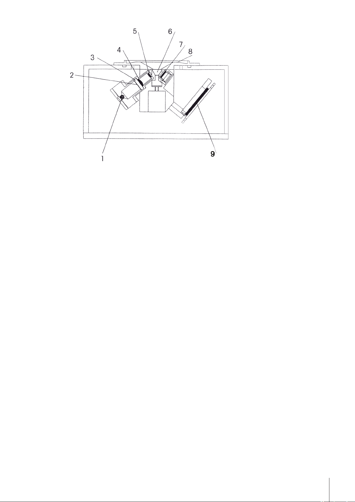
1: Light source
2: Polarization filter
3: Interference filter
4: Lens
5: Lens
6: Prism
7: Lens
8: Measuring cell
9: Optical sensor (CCD)
11Principles of Refractometry
Page 12

4Description of Functions
4.1Layout of the Terminal
The control panel of the terminal consists of an integrated touchscreen and the following buttons, located next
to the touch-sensitive surface of the display: You can press these buttons any time, regardless of which dialog
you are currently using.
●
Two Home buttons that bring you back to the Homescreen.
●
Info, opens the info screen that shows the data related to the specific device.
●
Reset that interrupts the ongoing task and processing of the pending tasks. To continue the waiting tasks,
open the task list (with the Tasks button) and click Resume.
4.2Operating the Touchscreen
The touchscreen is automatically activated when the instrument is switched on.
To select a button or an input element in the dialog window, you simply touch the screen using a soft blunt
object or a fingertip.
It is also possible to select input elements using a USB mouse. To do this, simply connect the mouse to a suit
able USB port on the instrument.
Never touch the surface of the touchscreen with pointed or sharp objects! This may damage the screen!
4.3Homescreen
Home is the first screen that is displayed when you start up the instrument or when you log in. Home is the
main screen. On the left-hand side of the screen you will see five buttons that lead to the following dialog win
dows:
●
Methods / Products: The button leads you to the method or product editor, in which you can create and
administer the methods or products (see "Methods and Products").
●
Series: In this dialog, you can create and manage series of individual samples, e.g. for using a sample
changer (see "Series").
●
Results: Here you administer the results of your analyses (see "Results and Statistics").
●
Setup: You can administer the following points here:
•
Adjustment and test sets
•
The hardware and all resources used by the instrument
•
User and global settings
•
Tables (internal and user defined) and auxiliary values
•
Maintenance and service of the instrument
●
Manual: This button takes you to manual operations.
In addition, there is another area that can be configured individually by each user (with the necessary autho
rization). Each user can store up to eight shortcuts here. With these shortcuts, defined methods, products,
series and manual operations can be started directly from the homescreen (see "Functional Description"): The
user interface > Shortcuts").
●
Standby display: The standby display continuously shows the current cell temperature (Tcell) and set tem
perature (Tset), even if no task is running.
Via the standby display in the Homescreen you open the Cell data dialog.
●
By pressing the home button on the control panel of the terminal, you return to Home.
See also
●
Methods and Products (page36)
●
Series (page60)
●
Results and Statistics (page62)
●
Shortcuts (page14)
12 Description of Functions
Page 13
4.4The User Interface
A
B
C
T
1
2
3
T
T
T
T
T
i
The graphical user interface consists of the following five basic elements:
●
The title bar at the top of the display specifies the name of the current dialog.
●
In the top right-hand corner you will see Tasks button, which signals the presence of ongoing processes
(see "Tasks and online screen: Tasks (page73)").
●
The navigation bar, located below the title bar, specifies the path to the current dialog.
●
The scroll bar on the right-hand side of the screen becomes visible if the content of the screen extends
beyond the viewable area. If this occurs, use either the arrows or the area in between them to move the
viewable area of the screen up or down.
●
Five buttons are located at the bottom of the screen. The function of these buttons varies and depends on
the context of the current dialog.
4.4.1Entering Data in the User Interface.
There are different types of input fields in the user interface. They allow you to enter data or select data from a
list. Input fields can also be deactivated and their contents are then displayed as information only and cannot
be changed in the corresponding dialog.
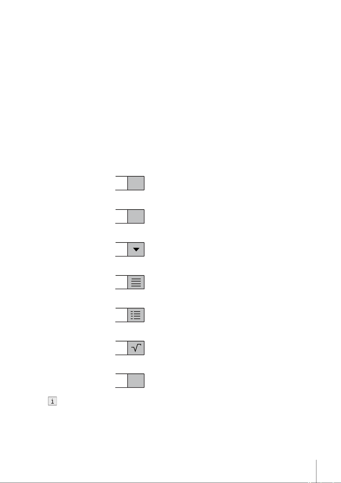
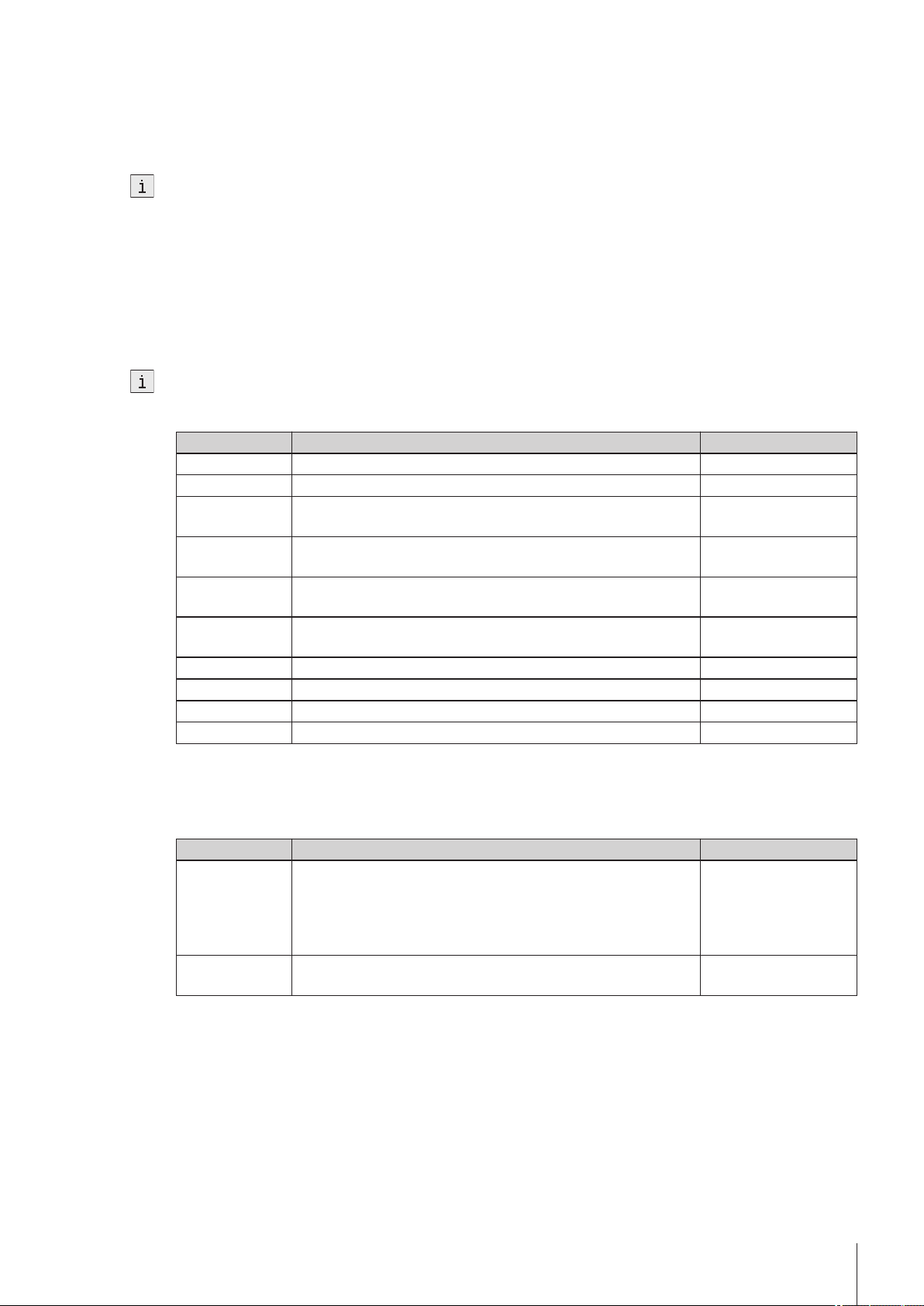
The various types of input fields are identified by an icon to the right of the screen:
Text input fields
Number input fields
Drop-down lists Selecting these fields opens a drop-down list from which you can
List fields Selecting these fields opens a menu list in a new window.
Parameter field Selecting these fields opens a new dialog with various additional para
Formula fields Freely definable formulas can be entered in these fields
In these fields text can be freely entered.
Numbers can be entered in these fields.
select an entry.
meters.
Info field
In addition to the input fields there are checkboxes that can be checked in order to select certain functionalities.
Checkboxes can affect the scope of the corresponding dialog, i.e. input fields can be hidden or visible depend
ing on whether the checkbox is checked.
The values in deactivated input fields are displayed as information only
and cannot be edited in the corresponding dialog.
13Description of Functions
Page 14
Sorting lists
There are lists that can be sorted alphabetically or numerically by column in ascending or descending order. To
do this, simply touch the parameter in the header row by which you would like to sort the list. A small arrow in
the header row indicates the parameter by which the list is sorted and whether it is sorted in ascending or
descending order.
4.4.2Shortcuts
Shortcuts allow you to start methods, series, and manual operations directly from the homepage. You can
locate shortcuts by means of the button AddToHome on the Homescreen. AddToHome is found in the respec
tive Start analysis dialog of the methods, products, series or of the manual operation.
Two types of shortcuts are supported.
Direct shortcuts which, when selected, start the task immediately without warning (only if the other settings
allow this), and
normal shortcuts which take you to the corresponding Start analysis start dialog from which you can start the
task.
Shortcuts are user-specific, i.e. each individual user can create shortcuts for the tasks that they would personal
ly like to conduct. Shortcuts are managed in Setup, under the subcategory "User Settings". Here you can delete
or modify shortcuts, or change their position on the Homescreen.
for methods
for products
for series
Shortcuts
(lead you initially to the
Start analysis dialog)
Direct shortcuts
(task starts immediately, directly and with
out advance warning)
for manual opera
tions
A maximum of 8 shortcuts can be saved on the Homescreen. As soon as this maximum is reached, "AddTo
Home" in the start dialogs of methods, products, series and manual operations is deactivated.
14 Description of Functions
Page 15
5Setup
This section tells you how to set up the refractometer acccordance with your requirements so that you can carry
out the measurements.
The following summary shows the buttons available in Setup for the various setting options:
Adjustment setsAdjustments & Tests Test sets
Hardware
User settings
Global settings
Maintenance & Service
Cell
Automation
External instruments
Peripherals
Sensors
Auxiliary instruments
Language
Screen
Beep
Shortcuts
Keyboards
System
User management
Analysis and resources behavior
Physical Properties
TablesTables & Values
Auxiliary values
MT service
Import / Export
Add external cell
Reset to factory settings
Firmware
Update
Hardware / Firmware summary
Cell
Touch screen adjustment
Export of adjustments / Tests / Measurements
The "Expired Resources" button
The Expired Resources button is located on the setup overview screen. It provides you with a summary of all
expired resources, stating the: type, name and expiration date of the respective resource.
Expired resources are entered if the setting "Monitoring adjustment set/test set/auxiliary value" is activated dur
ing setup.
Below you will find a detailed description of the setting options available in setup:
5.1Adjustments & Tests
Navigation: Home > Setup > Adjustments & Tests
Adjustment and test sets can be administered as described below. You can create new sets and delete existing
ones (when deleting you receive a prompt with the option to cancel). Before an adjustment or test can be per
formed, an adjustment or test set must be defined.
A maximum of six different adjustment sets or test sets respectively can be entered in the set list.
Before an adjustment or test can be performed, an adjustment or test set must be defined.
15Setup
Page 16
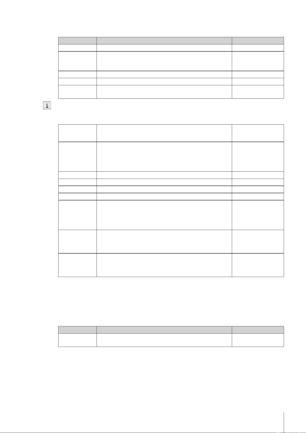
5.1.1Adjustment Sets
Via the button Adjustment sets you will obtain a list of the defined sets. The default set "Air&Water20.00C" is always available and cannot be deleted. When you click the sets, you obtain more detailed information about the individual sets. The parameters "Adjustment mode", "Temperature" and "Set name" are displayed.
Creating adjustment sets
You can create your own adjustment sets via the button New. The Adjustment set parameters dialog opens.
Parameters Description Displayed if
Adjustment mode Defines with which standard the adjustment will be performed.
Temperature Defines at which temperature the adjustment will be performed. Set name The set is uniquely identified in the system via this name. -
Delete adjustment sets
1 To delete a created set, click the desired entry in the Adjustment sets dialog.
2 In the Adjustment set parameters dialog, click the button Delete.
When a set is deleted, the set history will also be deleted. Methods that refer to the deleted set are no
longer executable.
5.1.2Test Sets
-
Set "Standards" requires a valid adjustment with "Air&Water" at
this temperature. (set "Air&Standard" and set "Water&Standard"
are not available for refractometers).
Via the button Test sets you receive a list of the defined sets. The default set "Water20.00C" is always available and cannot be deleted. When you click the test sets, you obtain more detailed information about the individual sets. The parameters "Test mode", "Temperature", "Set name" and depending on the mode "Standard name" are displayed.
Creating test sets
You can create your own test sets via the button New. The Test set parameters dialog is opened.
Parameters Description Displayed if
Test mode Defines with which standard the test will be performed. Temperature Defines at which temperature the test will be performed. Standard name Description of the standards "Test mode" = "Stan
Set name The set is uniquely identified in the system via this name. -
Delete test sets
1 To delete a created set, click the desired entry in the Test sets dialog.
2 In the Test set parameters dialog click the button Delete.
When a set is deleted, the set history will also be deleted. Methods that relate to the deleted set are no
longer executable.
5.2Hardware
Navigation: Setup>Hardware
In this dialog window you can configure all the hardware components connected to the meter. These include:
●
Cell
●
Automation
●
External instruments
●
Peripherals
●
Sensors
●
Auxiliary instruments
dard" or "Brix standard"
16 Setup
Page 17
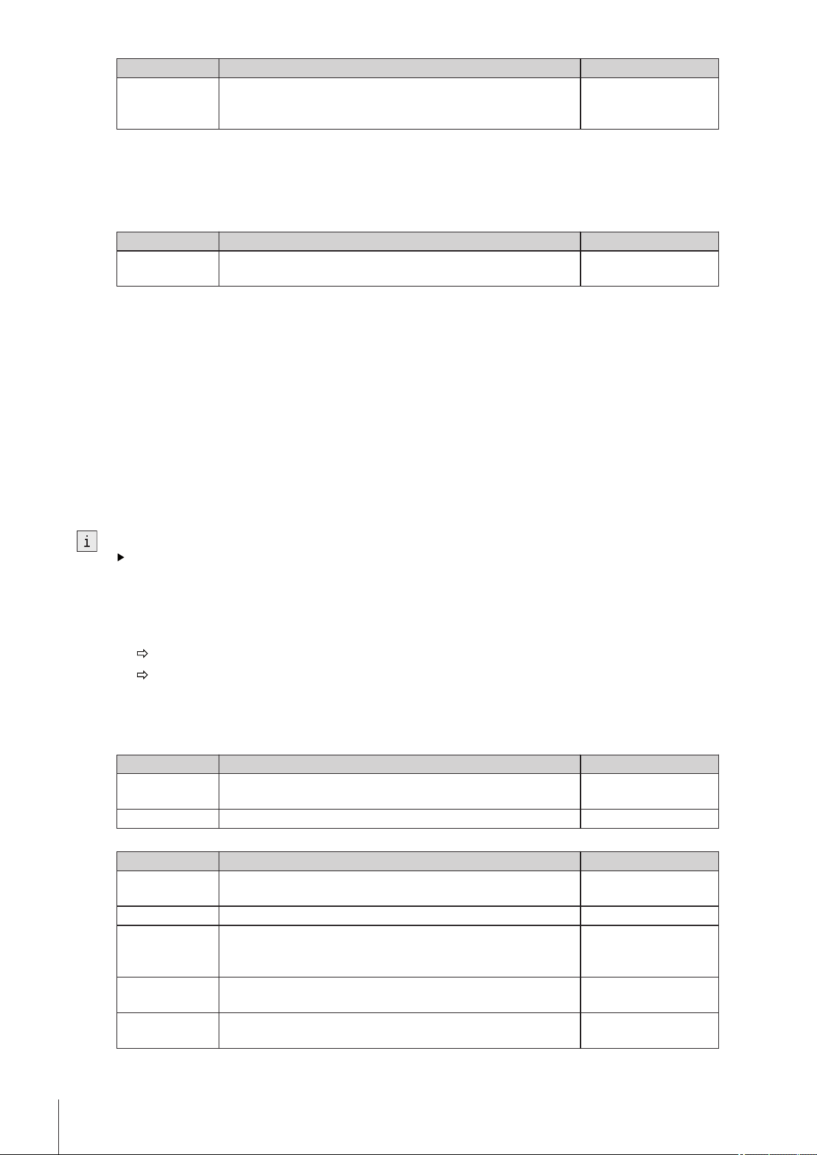
5.2.1Cell
Navigation: Home > Setup > Hardware > Cell
The measuring cell is connected via an internal interface in the compact device. The instrument can be extend
ed to create a 2–cell instrument (see also "Setup: Maintenance & Service > Add external cell (page33)").
– Touch the button Cell in the Hardware dialog.
Parameters Description Displayed if
Cell Name of the measuring cell Type Measuring cell type Status Shows whether the cell is connected. Serial number Serial number of the cell -
If an adjustment has been performed, an entry in the adjustment set appears in the setup of the corresponding
cell. If you touch the entry, the data of the most recent adjustment that was executed with the set will be dis
played.
Parameters Description Displayed if
Adjustment set By touching the set entry, you obtain the values for the most
Monitoring
adjustment set
Adjustment inter
val
Reminder Before the set expires, a message appears indicating that the
Days before expi
ration
If a test has been performed, an entry in the test set appears in the setup of the corresponding cell. If you touch
the entry, the data of the most recent adjustment that were executed with the set will be displayed.
Parameters Description Displayed if
Test set By touching the set you go to the values for the most recent test
Monitoring test
set
Test interval Service life of test "Monitoring test set"
Reminder Before the set expires, a message appears indicating that the
Days before expi
ration
Via the button History you go to a list that contains a maximum of ten adjustment or test entries for the selected
set. In the process the measured refractive index values are displayed (in the adjustment mode air and water
only the value for water). The history can be displayed in graphic form via the button Graph. You can view the
history data by touching an entry.
With single cell instruments you go directly to the list with the cell parameters
In the case of two cell instruments the connected cells are listed. You have to touch one of the displayed
cells so that the Cell parameters dialog opens.
The Cell parameters dialog is opened.
-
recent adjustment of this set.
Monitoring of the service life of the adjustment can be activated.
The process, if the service life of a set has expired, is defined in
the method function "Measure".
Validity of adjustment "Monitoring adjustment
set" activated
"Monitoring adjustment
adjustment or test has expired.
Specifies the number of days after which a warning is triggered. "Reminder" activated
for this set.
Monitoring of the service life of the test can be activated. The
process, if the service life of a set has expired, is defined in the
method function "Measure".
adjustment or test has expired.
Specifies the number of days after which a warning is triggered. "Reminder" activated
set / test set" activated
activated
"Monitoring adjustment
set / test set" activated
-
-
-
5.2.2Automation
Navigation: Home > Setup > Hardware > Automation
The automation units that can be installed are listed below:
17Setup
Page 18
●
DryPal (drying pump)
●
FillPal (sample pump)
●
SC1 (automation unit for a sample)
●
SC30 (automation unit for 30 samples)
●
InMotion (automation unit for up to 303 samples)
The peripheral devices have an automatic PnP (Plug and Play) – identification. They can also be manually cre
ated in the setup.
Via the button Automation in the Hardware dialog, you access a list with defined automation units. By touch
ing a list entry, you obtain more detailed information about the corresponding automation unit.
Parameters Description Displayed if
Type Instrument Type Power purge unit The external diaphragm (Optional) has a much higher output
than the diaphragm pump integrated in the SC1/SC30. The pump
"Type" = "SC1"/
"SC30"
is actually adjusted at the SC1/SC30.
Heating option This is where the heating option is activated. The temperature is
directly set on the heating unit.
Limit sensor Optical sensor that detects the sample and prevents it leaving the
heated area of the heating option (info field).
External drain
valve
Located in the heating unit. Prevents the samples flowing back
after filling process (info field).
"Type" = "SC1"/
"SC30"
"Type" = "SC1"/
"SC30"
"Type" = "SC1"/"SC30"
Solvent 1 Specifies the solvent at the connection Rinse 1 "Type" = "SC1"/
"SC30"
Solvent 2 Specifies the solvent at the connection Rinse 2 "Type" = "SC1"/
"SC30"
Speed "Low" Value for speed level "Low" of the FillPal or InMotion autosampler
(in % of the maximum speed).
Speed "Medium" Value for speed level "Medium" of the FillPal or InMotion
autosampler (in % of the maximum speed).
Speed "High" Value for speed level "High" of the FillPal or InMotion autosam
pler (in % of the maximum speed).
Rate at 100% Value for max. possible pump output (depending on the installed
"Type" = "FillPal" /
"InMotion"
"Type" = "FillPal" /
"InMotion"
"Type" = "FillPal" /
"InMotion"
"Type" = "InMotion"
pump which is defined as sampling pump).
Stirrer output Specifies the pump/stirrer port on the InMotion where your stirrer
"Type" = "InMotion"
is connected.
Sampling pump
output
PowerShower
output
Specifies the pump/stirrer port on the InMotion where your sam
pling pump is connected.
Specifies the pump/stirrer port on the InMotion where your pump
for PowerShower is connected.
"Type" = "InMotion"
"Type" = "InMotion"
Rate Value for required pump output for PowerShower. "Type" = "InMotion"
Beaker height Specifies the height of the used beakers. "Type" = "InMotion"
A distinction should be made between the following two cases in the installation of instruments:
1.
There is still no setup entry available in the unit (delivery state).
A new entry has been generated and the parameters automatically generated.
2.
A setup entry was previously manually created in the instrument:
The PnP parameters are automatically entered, the remaining parameters, previously edited by the user,
remain unchanged.
18 Setup
When a PnP instrument is unplugged, the status changes to "not installed".
Below is described how you can administer the various devices in setup. This includes the creation of devices
or changing the parameters in the setup.
Create automation units
So that methods for the application of automation units can be created and configured without the automation
unit being connected, these units must be created in the setup via the button New.
Page 19
Delete automation unit
It is not possible to delete the entry of a connected device.
If you want to delete an entry for a unit that is not connected from the list, a message with the termination
option appears indicating that after deletion the methods that use the external instruments will no longer be exe
cutable.
5.2.3External Instruments
Navigation: Home > Setup > Hardware > External instruments
The external instruments that can be installed are listed below. They all have automatic PnP – identification:
●
METTLER TOLEDO S20 – SevenEasy™ pH
●
METTLER TOLEDO S30 – SevenEasy™ Conductivity
●
METTLER TOLEDO S220 - SevenCompact™ pH/Ion
●
METTLER TOLEDO S220 - SevenCompact™ Conductivity
●
Lovibond colorimeters PFX880/ PFXi880, PFX950/ PFXi950 and PFX995/ PFXi995 series, Tintometer
●
Minolta colorimeters CM-5/ CR-5
●
The Lovibond colorimeters can be connected to the USB interfaces. For this purpose the USB – RS232
adapter is required (contained in the connection kit).
●
For each device type only one entry is possible.
Install devices
A distinction should be made between the following two cases in the installation of instruments:
1.
There is still no setup entry available in the unit (delivery state).
A new entry has been generated and the parameters automatically generated.
2.
A setup entry was previously manually created in the instrument:
The PnP parameters are automatically entered, the remaining parameters, previously edited by the user,
remain unchanged.
When a PnP instrument is unplugged, the status changes to "not installed".
●
Via the button External instruments in the Hardware dialog, you can obtain the list of instruments. By touching a list entry, you obtain more detailed information about the corresponding instrument.
Create device
So that methods can be created and configured with external instruments, without having to connect the instru
ment, the setup entries of the external instruments can be manually created via the button New.
●
The pH and conductivity meters can be assigned names individually using the "Instrument" parameter.
Delete devices
It is not possible to delete the entry of a connected device.
If you want to delete an entry for a unit that is not connected from the list, a message with the termination
option appears indicating that after deletion the methods that use the external instruments will no longer be exe
cutable.
SevenEasy™ / SevenCompact™ pH/ion and conductivity meters
1 Select the following for the SevenEasy™ and SevenCompact™ measuring instruments (also refer to the
operating instructions for the measuring instrument concerned):
Manual end point measured value acquisition,
set the unit [pH]" ([mV] not supported).
2 For the SevenCompact pH and conductivity meters, the following must also be selected (also refer to the rel
evant operating instructions):
an interval time of 1s (in menu>Interval measurements),
interface=printer (in menu>Data transmission),
"Send data to interface" (in "Type of data transmission").
19Setup
Page 20

3 For temperature compensation, set the unit [°C] at the measuring instruments. Two types of temperature
compensation exist:
- ATC (automatic temperature compensation) with a temperature sensor connected.
- MTC (manual temperature compensation) with no temperature sensor connected.
Note:
The pH or conductivity meters switch automatically, depending on the arrangement.
If the temperature unit at the pH meter or conductivity meter is set to [°C], the results "TpH" and "TCond" will
be converted to the temperature unit set in the instrument, i.e. either [°C] or [°F] . By contrast, if [°F] is set
at the pH or conductivity meter, no result will be calculated. "--" will be output in the results field.
The conductivity units are [mS/cm]/ [μS/cm] (depending on the range) or [mS/m][μS/m] (depending on the
range). However, the results are expressed in [μS/cm]. If you wish to have the result displayed in [mS/cm] or
[mS/m][μS/m], it will be necessary to recalculate the result using the "Calculation" method function.
Colorimeter
- Lovibond
The Lovibond colorimeter can be used for extinction or transmission measurements. The wavelengths are out
put in 5nm (in the range 420 – 710nm).
A color measurement may take longer than 25s.
- Minolta colorimeters CM-5 / CR-5
The Minolta colorimeters can be used for transmission measurements (liquids).
Transmission data are supplied in 10nm increments within the spectral range 360 – 740nm.
A color measurement takes approximately 1s.
The measurements involve high-energy light flashes. For this reason, color scales are not offered for reflection
measurements in the crude oil industry.
●
The CR-5 colorimeter does not supply any spectral data.
●
Calibration is possible directly at the colorimeter only. The USB link must be disconnected.
●
"Illuminant" and "Observer" can be set in the "Configuration" method function. For more information, see
"Methods and products: Method functions> Configuration (page42)".
- Color scales
Navigation: Home > Setup > Hardware > External instruments > Parameters
– Click on "Colorimeter".
The "External instrument parameters" dialog appears.
If a device has been connected, a list of color scales is displayed via the Color scales button, that were avail
able in the most recently connected device. If the device has been manually configured and no device has yet
been connected, then the list is empty.
See also
●
Continuous run (page71)
5.2.4Peripherals
Navigation: Home > Setup > Hardware > Peripherals
In the dialog Peripherals, the following devices and settings can be configured:
●
Barcode reader
●
USB stick
●
Fingerprint reader
●
Printer
●
Personal Computer (PC) – settings
●
Network settings
●
Network storage
20 Setup
Below is described how you can administer the various devices in setup. This includes the creation of devices
or changing the parameters in the setup.
Page 21
Barcode reader
Barcode readers have Plug&Play (PnP) recognition and can be installed via the USB interface.
The following barcode readers can be installed:
●
Handheld readers
●
Built-in readers
You can create the barcode readers via New. A maximum of one entry can be created for both types.
Parameters Description Displayed if
Type Instrument Type Serial number Serial number of the corresponding device Barcode Informa
tion
Sample ID: on the barcode there is only the sample ID.
Method ID: on the barcode there is the method ID (with this a
-
saved method can be selected during scanning).
Product ID: on the barcode there is the product ID (with this a
saved product can be selected during scanning).
Sample ID/Method ID: on the barcode there are the sample ID
and method ID (with this a saved method can be selected during
scanning).
Sample ID/Product ID: on the barcode there are the sample ID
and product ID (with this a saved product can be selected during
scanning).
Start pos. sample
ID
Number of char
acters
Start pos.
method ID
Number of char
acters
Start pos. prod
uct ID
Number of char
acters
Immediate start If this parameter has been activated, when a task is started with
Start position of the sample ID on the barcode "Barcode information"
with sample ID
Length of the sample ID on the barcode "Barcode information"
with sample ID
Start position of the method ID on the barcode "Barcode information"
with method ID
Length of the method ID on the barcode "Barcode information"
with method ID
Start position of the product ID on the barcode "Barcode information"
with product ID
Length of the product ID on the barcode "Barcode information"
with product ID
"Type" = "Handheld
the barcode reader, the Start analysis dialog is skipped and the
task is started immediately.
reader",
"Barcode information"
with method ID, product
ID or sample ID
Example of barcode with sample ID and method ID (161218522). (Sample ID=1612 and method ID 18522).
●
Start pos. sample ID 1
●
Number of characters 4
●
Start pos. method ID 5
●
Number of characters 5
USB stick
Commercially available USB sticks from USB Version 1.1 are supported.
Fingerprint reader
You can use a fingerprint reader to authenticate users on the titrator. In order to do this, the fingerprint reader
must be activated on the titrator. The following parameters are available for this:
Parameters Description Displayed if
Activate finger
Activates the connected fingerprint reader. -
print reader
21Setup
Page 22
Printer (and USB-RS232 data export)
●
Date can be printed with the USB-P25 (strip printer) or with a network printer.
●
Data can be exported using the USB data export box. The data are exported in the XML (UTF-8) formats.
●
For data export to an RS interface, you need the USB RS232 adapter (USB data export box).
●
As desired, data can be printed either as a summary or in a user defined format (via "Print Mode" parameter
"Report" method function; also see "Methods and products: Methods> Method functions> Report")
For printing/USB data export, the following should be taken into consideration:
●
In the "Report" method function, the "Print / USB-RS232 data export" parameter must be selected.
You can define the following parameters via the Printer button (Home>Setup>Hardware>Peripherals):
Parameters Description Displayed if
Printer type USB compact printer
The USB compact printer does not support all languages. This
printer can only print out a limited quantity of analysis data and
results.
USB-RS232 data export
For the RS-232 data export, the data is transmitted regardless of
the selected language. Only a limited quantity of data and results
can be exported.
Network printer
Every connected printer in your local network that supports HP
PLC 3 or Epson ESC/P 2 can be used.
Status Indicates whether the selected printer type is installed (info field). Only for printer type
"USB compact printer"
and "USB-RS232 data
export"
Baud rate The baud rate for data transmission via the USB-RS232 interface. "Printer type"= "USB-
RS232 data export"
Data bit The number of data bits is displayed (info field). "Printer type"= "USB-
RS232 data export"
Stop bit The number of stop bits is displayed (info field). "Printer type"= "USB-
RS232 data export"
Parity Defines the parity protocol. ("Even", "Odd", "None") . "Printer type"= "USB-
RS232 data export"
Handshake Data transmission via the RS-232 interface ("Xon-Xoff", "None"). "Printer type"= "USB-
RS232 data export"
Type Choose the printer protocol. "Printer type"= "Net
work printer"
Network name Define your local network name here. "Printer type"= "Net
work printer"
Port number Define your local port number here. "Printer type"= "Net
work printer"
Paper size Choose the print-format of the report (A4 / Letter). "Printer type"= "Net
work printer"
22 Setup
PC settings
Only one PC connected per measuring instrument can be present at one time. You can select if you wish to set
up a connection to the laboratory program "LabX".
Parameters Description Displayed if
Set up connec
tion to LabX at
If this parameter is activated, a connection to LabX will be estab
lished on startup.
-
start up
Changes to the PC settings are not implemented until after the measuring instrument is rebooted.
Page 23
Network settings
You can define the following parameters for the network – settings:
Parameters Description Displayed if
Type Type of network connection Obtain IP
address auto
matically
IP Address IP address of the instrument Subnet mask Subnet mask of the device Standard gate
way
The device automatically reboots after any change to the network settings.
Network storage
You can define the following parameters for a network – storage:
Transfer via Method for transferring data
Server PC or server name. Users should have read-write access. Maxi
Share name Name of the share folder User name Define your own user name. Domain Domain name for the user. Password Password for network share. Target folder Name of target folder for PDFs or results.
First folder level Can optional be used to sort data. (None | User name | Instru
Second folder
level
If this device has been activated, the device automatically obtains
an IP address.
Standard gateway of the device "Type" = "Ethernet"
Default: Network share
mum 60 alphanumeric characters.
Arbitrary IP address or name of server (for network share, only
server name allowed).
A pdf_export folder and a results folder are automatically creat
ed in the target folder when specified. If no target folder is speci
fied the folders are created in the root folder.
ment ID | Date | Method ID | Analysis comment)
Default: None
Can optional be used to sort data. (None | User name | Instru
ment ID | Date | Method ID | Analysis comment)
Default: None
"Type" = "Ethernet"
-
-
-
-
"First level folder" =
activated
5.2.5Sensors
Navigation: Home > Setup > Hardware > Sensors
Sensors can be activated in the setup. The following sensors can be connected:
ErgoSens: Infrared sensor for contactless start of measurement (see "Analysis sequence: Start of analyses").
Before you can use ErgoSens, it has to be activated:
Parameters Description Displayed if
Activate
ErgoSens
WasteSens or LevelSens: Level sensors for waste bottle.
It is determined whether the maximum filling level of the waste bottle is reached. If the maximum filling level
has been reached, a message appears prompting the operator to empty the waste bottle. The task is then inter
rupted.
Before you can use WasteSens or LevelSens, it has to be activated:
Activates the ErgoSens -
23Setup
Page 24
Parameters Description Displayed if
Activate
WasteSens/Lev
elSens
If you connect the density - module, you can use an air pressure sensor:
AtmoSens: Atmospheric pressure sensor for measuring the absolute air pressure.
If an AtmoSens is connected, the atmospheric pressure (if required) is measured with the AtmoSens. If no
AtmoSens is connected, the air pressure is read out from the current value from Home > Setup > Global
settings> Physical properties.
Parameters Description Displayed if
Verify AtmoSens
availability
activates the WasteSens or LevelSens -
If this parameter is activated, the use of the AtmoSens is enforced
for tasks which require the pressure.
5.2.6Auxiliary instruments
Navigation: Setup>Hardware>Auxiliary Instruments
Auxiliary instruments can be any instruments that access the 24V output or USB-RS232 adapter of the measur
ing instrument and that are to be used in a method.
An auxiliary instrument that accesses the 24V output is switched on for a predefined period and then switched
off again via the corresponding command. The instruments are controlled via the "Auxiliary instrument" method
function.
Auxiliary instruments form part of a method, while peripheral devices are classified as input/output devices
(printers, barcode readers etc.), which do not have direct access to methods.
Starting from the auxiliary instrument list, you can add new auxiliary instruments or select existing ones or
modify their parameters. In addition, the selected auxiliary instruments can be deleted.
A maximum of 30 auxiliary instruments can be entered.
Choose the New button in the Auxiliary Instruments dialog window to open the Auxiliary Instrument Para meters dialog.
-
1 Before a new auxiliary instrument can be added, you must first use the "Control type" parameter to select
the manner in which the auxiliary instrument is to be controlled:. The following values are available for
"Control type":
24V output
USB-RS-232
2 You can assign a name of your choice to the auxiliary instrument.
The parameters for the control types are listed below:
24V output
Parameters Description Displayed if
Control type Indicates which port on the measuring instrument is to be used
for the auxiliary instrument.
Name A name of your choice. -
USB-RS-232 interface
Parameters Description Displayed if
Control type Indicates which port on the measuring instrument is to be used
for the auxiliary instrument.
Name A name of your choice. Adapter Defines which adapter is used. Maximum 2 auxiliary instruments
of type USB-RS-232 can be used in the same method (by using
adapter 1 and 2)
Baud rate The baud rate for data transmission via the RS-232 interface of
the adapter.
Data bit Defines the number of data bits. "Control type" = "USB-
"Control type" = "USBRS232"
"Control type" = "USBRS232"
RS232"
-
-
24 Setup
Page 25
Stop bit Defines the number of stop bits. (2 stop bits can only be selected
Parity Defines the parity protocol. "Control type" = "USB-
Handshake Data transmission via the RS-232 interface of the adapter. "Control type" = "USB-
A suitable adapter (USB data export box) is required for the USB-RS-232 connection.
5.3User settings
Navigation: > >
These settings contains the options that can be made specifically for each currently logged in user.
You can configure the language, the screen settings (for the touchscreen), the layout of the alphanumeric and
numeric keyboard, the use of beeps, and shortcuts for each user.
5.3.1Language
Navigation: Home > Setup > User settings > Language
The following languages are available:
●
German
●
English
●
French
●
Italian
●
Polish
●
Portuguese
●
Spanish
●
Chinese
●
Russian
if 7 data bits are also selected at the same time.)
"Control type" = "USBRS232"
RS232"
RS232"
The language can be defined both for the operation of the terminal as well as for the protocols that are to be
printed out from a printer.
Parameters Description Displayed if
Touchscreen Language of the user interface Report Language of the printout* -
*
Chinese can not be selected as language for reports
5.3.2Screen
Navigation: Home > Setup > User – settings > Screen
The following parameters can be set in the screen settings:
Parameters Description Displayed if
Primary color Color of the user interface Brightness Brightness of the display Button shape Shape of buttons on the touchscreen Screen saver Activates screen saver Wait time Time for the display of the screen saver Activates screen saver
5.3.3Beep
Navigation: Home > Setup > User settings> Beep
The audio signal is set specifically for each user. You can activate the audio signal in the Audio-Signal set
tings dialog.
Parameters Description Displayed if
25Setup
Page 26
5.3.4Shortcuts
Navigation: Home > Setup > User – settings > Shortcuts
In this dialog, every user has the opportunity to administer his or her own selected shortcuts.
The list of all shortcuts for the logged in user can be viewed. Individual shortcuts can be selected and deleted.
You can determine the following parameters:
Parameters Description Displayed if
Description This text is the name of the shortcut that is displayed in the
Immediate start When the shortcut is pressed, the display switches directly over
Homescreen
Position
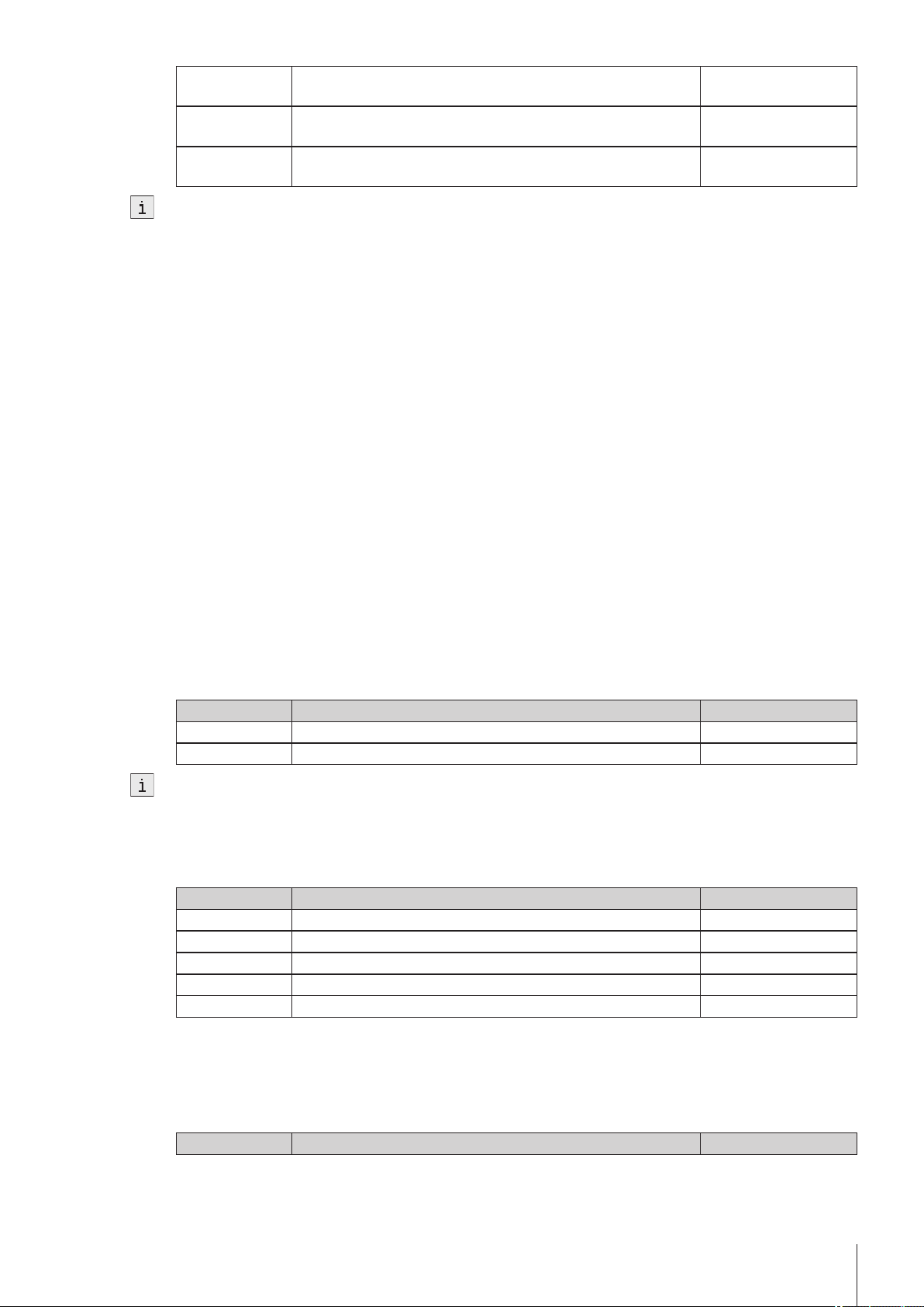
5.3.5Keyboards
Navigation: Home > Setup > User – settings > Keyboards
In the Keyboard settings dialog, you can define the layout for the alphanumeric and the numeric input fields.
The following settings are available:
Parameters Description Displayed if
ABC keyboard Defines the layout of the alphanumeric input field. 123 keyboard Defines the arrangement of the keys for the numeric input field. -
Homescreen.
to the online screen without opening the Start analysis dialog.
Selection of the position on the Homescreen -
5.4Global Settings
Navigation: Home > Setup > Global setting
In the Global Settings, you can make general settings to the measuring instrument that apply to all users of the instrument. The settings in this dialog can only be changed by users with the appropriate authorizations.
Global settings include:
●
The system settings
●
User management for creating user accounts and assigning rights.
●
The settings for Analysis and resources behavior.
●
Physical properties for defining the "Temperature unit" and the air pressure.
5.4.1System
Navigation: Home > Setup > Global settings > System
In the System settings dialog the following buttons are available:
●
Identification:In this menu you can give the measuring instrument a freely definable ID consisting of at
least four characters.
In addition the following information is displayed: Device, serial number and firmware version.
●
Date / time:You can define the format used to display the date and time and set the device date and time.
●
Data storage: If this parameter is activated, all results that are saved under Home > Results are deleted
(only when device is shut down).
5.4.2User Management
Navigation: Home > Setup > Global settings > User management
By means of the User management dialog you can administer users and account policies for the instrument.
A maximum of 30 different users can be defined, from which only maximum one may be logged in with the
instrument (1 user operation).
User accounts can be deleted and edited.
There is a default user with the user name "Administrator" (user group: Administrators). This cannot be deleted.
26 Setup
Page 27
5.4.2.1Users
Navigation: Home > Setup > Global settings > User management > User
Via the button New in the User dialog you can open the User parameters of the dialog. It is possible to define
new users here.
"User management" is the only area in which users with administrator rights are able to edit settings and, there
fore, create or make changes to users.
Create a new user in the User parameters dialog as follows:
1 Define a user name.
2 Assign the user to a group. The following user groups are available:
Administrator
Expert
Technician
Operator
For information on the rights of these user groups, see "Setup (Setup: Global settings> User management>
User groups (page27)".
The following parameters are available in the User parameters dialog:
Parameters Description Displayed if
User name The user is uniquely identified in the system via the name. Full Name Complete name of the user. User Group Selection of the user group for the user. Depending on the user
Reset password Resets the password for the user to "123456". Activates "Enforce pass
Lock user Locks the user. Activates "Enforce pass
Enforce pass
word change
Created by The administrator logged in at time of creation Created on Date of creation and time (info field) Modified by The administrator logged in at time of creation Modified at Change date and time (info field) -
-
group the user has various rights.
word/fingerprint"
word/fingerprint"
With the next login the entry of a new password will be enforced. Activates "Enforce pass
word/fingerprint"
5.4.2.2Account Policy
Navigation: Home > Setup > Global setting > User management > Account policies
The following parameters can be edited in the dialog:
Parameters Description Displayed if
Enforce pass
word/fingerprint
Min. password
length
If the parameter "Enforce password" is deactivated, then the instrument starts directly, i.e. not via the login
screen (only if one user is defined – corresponds to the factory settings). If several users are defined, the user
name can be selected in the login screen from a list.
5.4.2.3User Groups
Each user is assigned to a user group. The following four user groups (with decreasing rights going down
ward) should be distinguished:
●
Administrator
●
Expert
If this parameter has been activated, you can only log in by
entering the password (or via the fingerprint reader, if the para
meter "Activate fingerprint reader" is activated, in Home >
Setup > Hardware > Peripherals > Fingerprint
reader).
The minimum length of the user passwords Activates "Enforce pass
word/fingerprint"
-
27Setup
Page 28

●
Technician
●
Operator
The following table presents the user rights that are assigned to the corresponding user group:
List of user rights
Right Minimum required user group
Start analysis via Shortcuts. Operator
Start analysis via Start button in the Homescreen Operator
Start analysis with ErgoSens Operator
Start analysis from method editor (for method type:
Technician
measurement, cleaning and test), product and series
editor (for method type: measurement, cleaning, test
and adjustment)
Adding/deleting items for series in the Start analysis
Technician
dialog (does not apply for adjustment-type methods)
Executing manual operations Technician
Editing shortcuts
Technician
(Setup>User settings)
Including and excluding results Technician
Deleting results Expert
Adding/deleting items for series in the Start analysis
Expert
dialog (also applies for adjustment-type methods)
Setting the language for touchscreen and reports Expert
Start analysis from method editor (for method type:
Expert
measurement, cleaning, test and adjustment)
Editing methods, products, series Expert
Editing "Adjustments & Tests"
Expert
(Home > Setup )
Editing "Hardware"
Expert
(Home > Setup)
Editing "Analysis and resources behavior"
Expert
(Home > Setup > Global setting)
Editing "Tables & Values"
Expert
(Home > Setup)
Setting the language for reports Expert
Editing "Physical properties"
Expert
(Home > Setup > Global setting)
Running "Maintenance & Service" in Home >
Setup, except:
●
Importing/exporting user management and memo
Expert
ry copy
Running "Maintenance & Service"
(Home > Setup),
including:
●
Importing/exporting user management and memo
ry copy
Editing "User management"
(Home > Setup > Global setting)
5.4.3Analysis and Resources Behavior
Navigation: Home > Setup > Global settings > Analysis and resources behavior.
The following settings can be defined:
28 Setup
Administrator
Administrator
Page 29

Parameters Description Displayed if
Show required
resources at start
Confirm end of
the analysis
Reset statistics if
sample ID
changes
Verify USB stick
availability
Verify printer
availability
Information on
identification of
PnP resources
Verify network
storage availabil
ity
If this parameter is activated, all resources are shown during
startup that are required for performance of the analysis.
Note: If a required resource is not available, the "Needed
resources" dialog is also shown without this parameter having
being activated.
If this parameter is activated, the OK button is shown at the end
of the task. The task is not ended until you confirm with OK. This
parameter is especially used if the result should remain on the
online screen at the end of the measurement so that, for exam
ple, it can be copied.
If this parameter is activated, the rolling statistics will be interrupt
ed, if the sample ID differs from the previous analysis. If it is not
activated, the rolling statistics will only be interrupted if the
method ID (or product ID) differs from the previous analysis.
If this parameter is activated and a USB stick is used in the
method, the task will be checked when the start is started to see
if the USB stick is available. If none is available the task cannot
be started.
If this parameter is activated and a printer is used in the method,
the task will be checked when the task is started to see if the
printer is available. If the printer is not available the task cannot
be started (does not work for network printers).
If this parameter is activated, a message is shown when a PnP
resource is detected.
If this parameter is activated and network storage is used in the
method, the task will be checked when the task is started to see if
a network storage is available. If no network storage is available,
the task cannot be started.
-
-
-
-
-
-
-
5.4.4Physical Properties
Navigation: Home > Setup > Global setting > Physical properties
In the Physical properties dialog you can defined the parameters "Temperature unit" [oC] or [oF] and "Atmospheric pressure" in [hPa].
Parameters Description Displayed if
Temperature unit Temperature unit applicable for all ranges of the instrument
(global setting). Either Celsius or Fahrenheit can be selected. All
inputs or outputs are in the temperature unit selected here. The
setting is saved after a restart.
Atmospheric
pressure
The atmospheric pressure is only required when using the density - module.
Input of atmospheric pressure that is used for calculating the
nominal value of the air density. The atmospheric pressure is
required for an adjustment or a test with air or a cell test. If the
AtmoSens is connected, the reading will be displayed here.
5.5Tables & Values
Navigation: Home > Setup > Tables & values
The instrument has tables and auxiliary values that can be used for the calculation of results (see also "Results
(page62)").
With measurements the raw data (e.g. temperature value and refractive index) are delivered. These results are
fed into the relevant tables so that corresponding results can be displayed in the respective units.
Tables are always assigned to an application. The list can be sorted according to application.
There are two types of tables:
-
-
29Setup
Page 30

●
METTLER TOLEDO tables:
These tables are included in the factory settings, they are only listed and can be neither edited, viewed nor
deleted.
●
User-defined tables:
Tables are laid out in the form of a value table (X-Y). They can be created, edited and deleted.
Below is a description of how to create your own tables.
In addition to the tables, you can also administer the auxiliary values in setup. The auxiliary values can thereby
be used in formulas. By means of the method function "Auxiliary value", an auxiliary value from any desired
formula can be assigned raw data or calculated results.
See also
●
Results and Statistics (page62)
5.5.1Tables
Navigation: Home > Setup > Tables & values > Tables
By opening the Tables dialog you can see a list of available tables (METTLER TOLEDO and user-defined).
How to create tables in the setup is described below.
You can create a table with the New button.
Parameters Description Displayed if
Name Table name: The name uniquely identifies the table in the system.
Application Application area of table. Facilitates the sorting of the table list. Input value Table heading for the input value. Output value Table heading for the output value. Fit type Definition of the curve type for the calculation.
1 Save the new table.
2 Enter value pairs via New.
Parameters Description Displayed if
"Input value" Input value of the value pair (corresponding to the measuring cell
"Output value" Output value of the value pair (e.g. Brix) -
At least four value pairs must be entered and then saved via the Save button.
– Touch the button Graph. The fit function is graphically presented (the button Graph is only displayed if the
table has been saved).
Note: The axis labeling corresponds to the specified "Input" – (x-axis) and "Output" parameters (y-axis).
The table has been successfully entered. The coefficients are calculated according to the selected function.
There is a "delta" column that shows the deviation from the calculated value at the effective table point (only
for the "Fit type" = "Polynomial"). This column is not shown when the table is being edited.
The name is entered into the formula in the method function "Cal
culation".
-
• Linear interpolation: Corresponds to a segmented curve.
• Lagrange interpolation: Lagrange fit via four points
• 1 order polynom
• 2 order polynom
• 3 order polynom
A dialog opens with the name of the new table.
used, e.g. density or refractive index)
30 Setup
●
In the Table – parameters dialog, you can again remove the table via the Delete button.
●
A table must contain at least 4 and contain a maximum of 200 value pairs.
●
A maximum of 30 user-defined tables may be defined.
●
Tables cannot be deleted or modified when they are currently in use.
●
The table name must be unique.
Page 31

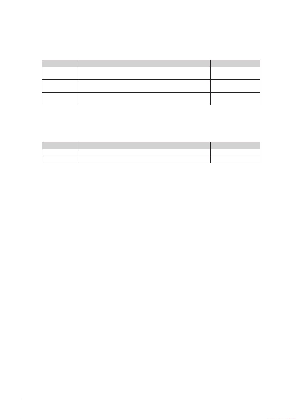
5.5.2Auxiliary Values
Navigation: Home > Setup > Tables & Values> Auxiliary values
Via the New button, you open the Auxiliary values parameters dialog. In it you can use the following parame
ters to define the auxiliary value:
Parameters Description Displayed if
Name Unique designation of the auxiliary value: The name is entered
Comment Short comment on the auxiliary value (e.g. about the unit) Value Numerical value Determination
method
Determination
date
Performed by Person who performed determination Monitoring auxil
iary value
Interval Specifies the time period for monitoring of the auxiliary value. "Monitoring auxiliary
Expiry date Expiry date of auxiliary value (info field) "Monitoring auxiliary
Reminder Defines whether a reminder should be issued before expiry of the
Days before expi
ration
●
A maximum of 100 auxiliary values can be saved in the instrument.
●
Auxiliary values cannot be deleted or modified when they are currently in use.
●
When an auxiliary value is assigned with the "Auxiliary value" method function, this is updated in the setup
immediately after completion of the method function.
-
into the formula in the method function "Calculation".
Type of determination method (info field) -
Date on which determination was performed (info field) -
Specifies whether the auxiliary value is to be monitored. -
value" activated
value" activated
"Monitoring auxiliary
auxiliary value.
value" activated
Specifies the number of days after which a warning is triggered. "Reminder" activated
5.6Maintenance & Service
Navigation: Home > Setup > Maintenance & Service
The following functions are available to you:
●
MT service
●
Import / Export
●
Add external cell
●
Reset to factory settings
●
Firmware
●
Update
●
Hardware / Firmware summary
●
Cell
•
One-point temperature alignment (only for density - module)
•
Whole-range temperature alignment
•
Fan check
•
Add manual adjustment
●
Export of adjustments / tests / measurements
5.6.1MT Service
Navigation: Home > Setup > Maintenance & Service> MT Service
31Setup
Page 32

Via the button MT Service you can open the Last MT services dialog window.
In this dialog, you can view and print out a list of the most recent (max. 10) METTLER TOLEDO services. Under
each date, the user name of the METTLER TOLEDO service technicians and the date and time of the service
appointment are displayed. The most recently performed service always appears at the top of the list.
Via the Settings button in the Last MT services dialog window you can open the Service data dialog window,
via which you can edit the service life of the last service due date. You can define whether a warning should be
issued before the service life expires (requires administrator rights). You can define the following parameters:
●
"Service life" (in days) of the most recently performed service.
●
"Reminder": Defines whether a reminder should be issued before expiry of the service life of the service.
●
"Days before expiration" Number of days before expiration of the service life on which the instrument should
issue a warning.
The entered value must be smaller than the value for the service life (only appears if "Reminder" has been
activated).
5.6.2Import / Export
Navigation: Home > Setup > Maintenance & Service> Import / Export
With the aid of this feature you can save the data on a UBS stick (export) or import data from a stick.
The following can be imported or exported:
●
Single method
●
All methods
●
Single product
●
All products
●
Single series
●
All series
●
Single table (only affects user-specific tables)
●
All tables (only affects user-specific tables)
●
User management
●
Memory copy
The following rules apply for Import / Export:
1.
Import/Export is only possible when a USB stick is connected.
2.
Import/Export is only possible when no task is running.
3.
Products can only be imported if referenced methods are already available on the device required for the
import.
4.
Series can only be imported if referenced methods or products of the series are already available on the
device required for the import.
– In the Maintenance & Service dialog, open the Import / Export dialog window. In this dialog, you can
define the following parameters:
"Action": Data can be exported to a USB stick or imported back from a USB stick.
"Data": Data that is to be exported or imported can be selected.
Memory copy
You can create a memory copy from your data. This includes adjustment and test data, auxiliary values, short
cuts and fingerprints, data relating to automation, peripherals and external instruments. When a firmware
upgrade of the instrument has to be done, the instrument can be restored from the memory copy. The memory
copy can also be imported to another instrument. In this case, the Test and Adjustment history are not imported
and an adjustment of the instrument is required.
Uploading data from a backup copy results in the existing data being overwritten by the data in the memory
copy. In this way you can restore the initial status.
32 Setup
Page 33

●
Not contained in a memory copy are
any saved results, default parameters for manual operations, internal tables, hardware for cell creation or
parameters for added external cells.
●
When you import / export user management settings the entire user management settings with all users and
their properties are exported or imported.
●
If the import is canceled, all previously imported users are deleted and only a default user (administrator) is
created.
●
You must have administrator rights before you can create and reimport a backup copy.
5.6.3Add External Cell
Navigation: Home > Setup > Mainten. & Service > Add external cell
Perform the action "Add external cell". In the Cell dialog box, the cell type must be selected (Home > Setup
> Hardware > Cell).
When you connect the external cell (module), the status changes to "installed" and the effective serial number
is entered.
If the external cell is removed, the entry in the cell list is retained. The status changes to "not installed". The seri
al number and the cell type however continue to be displayed.
5.6.4Reset to Factory Settings
Navigation: Home > Setup > Maintenance & Service > Reset to factory settings
With the button Reset to factory settings you can reset your settings.
If you do this all created data, amendments, settings, setup entries or results are lost.
Before you activate "Reset to factory settings" you should create a memory copy.
5.6.5Firmware
Navigation: Home > Setup > Maintenance & Service > Firmware
With the aid of this feature you can display a list showing the most recent firmware updates. The first entry in
the list corresponds to initial operation.
All list entries are saved with a date and FW version.
5.6.6Update
Navigation: Home > Setup > Maintenance & Service > Update
With the aid of this feature a firmware update of the instrument, device board and cells can be performed via a USB stick. After the button update is touched, all available and associated components that contain firmware are presented in a list (Instrument FW, cell FW, Device Board FW).
You must have administrator access rights.
- The instrument is in idle mode (no task is active).
- To update a cell, the cell must be connected. In the process each update must be performed separately for
each connected cell that is to be updated.
1 Via the button update you can open the Firmware – List dialog. Select the relevant components from this
list.
2 Plug in the USB stick with the firmware update files into the instrument.
The instrument recognizes the USB stick and enables the update.
3 Start the update.
The instrument reboots and starts the update program via the USB stick. The update can be performed in
the update program.
4 When the update program is terminated, the instrument reboots with the normal application.
Instrument update:
33Setup
Page 34

All results, settings, setup entries, methods, products and individual modifications are lost during the instrument
firmware update. On the other hand, the service history, the instrument firmware history and serial number are
all retained.
Cell update:
●
Only updates from connected and recognized cells are offered, whose update file is on the USB stick.
●
With the cell update, no changes are made to the application program and to the individual settings and
methods.
Device board update:
With the device board update, no changes are made to the application program and to the individual settings
and methods.
5.6.7Hardware / Firmware summary
Navigation: Home > Setup > Maintenance & Service > Hardware / Firmware summary
You can view a list with all connected components along with the corresponding information on hardware or
firmware. The list can be saved as a file on a USB stick. The file name contains the serial number of the device
and the current date and time. Example:
HW_SW_Info_5124560983_23_03_2010_08_23.cvs
5.6.8Board Tests
Navigation: Home > Setup > Maintenance & Service > Board tests
With this function, the interfaces of various boards can be tested:
●
Main board
●
Device board
●
External cell board, if an external cell is connected
The sequence for testing the boards is described below:
1 Via the button Board tests you can open the Boards dialog. In this dialog, buttons are provided, which
2 Touch the button for the desired board and you will receive an information list with the connections on the
3 Touch the Start button, to go to the list of test functions.
4 You can select another interface and proceed as described above or you can cancel the test with the Stop
5.6.9Cell
Navigation: Home > Setup > Maintenance & Service > Cell
Via the Cell you get to the service function of the cells.
This dialog window contains the following buttons:
Button Parameters
One-point temperature alignment Adjustment of the cell temperature to the set temperature. The
guide you to the corresponding board information for the connections.
board and the required resources that must be plugged into the corresponding connection.
- By touching a test, you change over to the corresponding test and this can then be started. Pop-ups guide
you through the test process and show you any errors identified.
- The test result is also displayed in the interface list.
button.
When all interfaces for the selected board have been tested and all have the status "successfully
passed", the results can be written onto the USB stick.
block thermistor is adjusted to the certified cell thermistor at the
current set temperature.
The One-point temperature alignment dialog shows the selected
cell, the set (Tset), the cell (Tcell) and the cell block temperature
(Tblock).
34 Setup
Page 35

Button Parameters
Whole-range temperature alignment Adjustment of the cell temperature to the set temperature across
the entire temperature range.
Note: The alignment takes about two hours.
The Whole range temperature alignment dialog shows the selected cell, the current values of the set (Tset),
cell (Tcell), cell block- (Tblock) and the ambient temperature (Tambient).
The alignment can be started when the temperature in the cell is stable and the cell is dry and clean.
Note:
●
If there is an error message, the current values are saved on the display so that it can be seen at which
temperature the error occurred.
●
With Stop the alignment can be interrupted at any time.
●
During alignment, the temperature per interval is saved in a file. This file can be saved on the USB stick.
Fan check The functional efficiency of the fans is tested.
The display is periodically updated.
Note: The instrument is not switched off when there is an error
display.
Add manual adjustment This function simulates an adjustment. It is used in order to per
form a measurement without previously adjusting the instrument.
Note: Only use for demonstration or method development
processes!
5.6.10Export Adjustments / Tests / Measurements
Navigation: Home > Setup > Maintenance & Service > Export of adjustments /
Tests / Measurements
With the aid of this function, the adjustment, test and measurement history can be saved on the USB stick so
that it can then be imported into an EXCEL file.
●
The histories can be viewed and exported.
●
The measurement history is only exported if the measured data agree with the current cell configuration (if
the external cell type is changed, the measured data cannot be exported from the previous cell).
35Setup
Page 36

6Methods and Products
Before you can perform a measurement you need a method. A method is an analysis program and consists of
a sequence of method functions (some with method subfunctions), which are processed by the instrument in
sequence.
Products are always linked to a method, and multiple products can be linked to the same method. It is therefore
possible to work with only a few methods.
Using the Print button, you can generate a PDF file containing the methods or product parameters and product
calculations.
The Print button is active only when a USB stick is connected.
How to create methods and products, how to access them and apply them is described below.
6.1Methods
A method basically consists of the configuration, sample feed, the actual measurement, cleaning, result calcu
lation and the creation of a report. These steps are defined as functions. The individual functions in turn consist
of parameters, whose values or names can be changed.
Method types
The instrument distinguishes between the following method types with different objectives:
●
MS (Measurement), for the performance of a measurement
●
ADJ (Adjustment), for an adjustment of the measuring cell(s)
●
TE (Test), for testing the measuring cell(s)
●
CL (Cleaning), for cleaning the measuring cell(s)
6.1.1Establishing Methods
When creating methods (max. number of methods: 30) you can make use of method templates with prede
fined method types and hence structures. The corresponding parameters thereby contain suitable default val
ues.
Select: Home > Methods / Products > Methods
1 Choose New to create a new method on the basis of a template.
2 Select the desired method type from the available templates. Now you can adjust this method to your own
specifications by adding or deleting method functions, or by adjusting the settings.
After a template has been chosen, the Configuration dialog opens. Here, according to the defined setup,
you can select the cell mode, the cell, automation unit and the external devices (pH, conductivity and
colorimeter) with which you wish to carry out the method.
Parameters Description Displayed if
Cell mode Defines the cell(s) Automation Defines the automation unit used by the method. The choice
available depends on the automation units defined in Home >
Setup > Hardware > Automation.
Note
●
●
-
If the filling and rinsing is performed with "FillPal" and drying
with "DryPal", then "FillPal+DryPal" must be selected.
If the InMotion autosampler is used together with a DryPal in
method type "Clean", both (InMotion and DryPal) must be
selected.
Lid handling Defines whether CoverUp (optional lid handling system on InMo
36 Methods and Products
tion) is used in the method.
Automation unit"=
"InMotion"
Page 37

pH Defines whether the pH meter is used in the method. "Method type"= "Mea
surement"
pH meter is defined in
"Home > Setup >
Hardware >
External
instruments".
Conductivity Defines whether the conductivity meter is used in the method. "Method type"= "Mea
surement"
Conductivity meter is
defined in "Home >
Setup > Hardware
> External
instruments"
Color Defines whether the colorimeter is used in the method. "Method type"= "Mea
surement"
Colorimeter is defined in
"Home > Setup >
Hardware >
External
instruments".
Up to the automation unit, these settings cannot be retrospectively modified.
Color settings
(Minolta only)
Illuminant The following illuminants can be selected:
Observer Viewing angle:
Activates "Illuminant" so that the illuminant type can be defined
and "Observer" so that the angle can be entered.
A, C, D65, D50, ID65, ID50, F2 to F12
2°C or 10°C; default 2°C
-
"Color settings" (Minol
ta only)" activated
"Color settings" (Minol
ta only)" activated
The parameters "Color settings" (Minolta only), "Illuminant" and "Observer" are used only with Minolta col
orimeters.
1 Confirm with OK.
2 In the "Title" method function, enter a new method ID. Afterwards, the new method will be stored under this
method ID.
3 Save the method.
You have now created a new method with its own ID. This method already has predefined method func
tions. To change the method functions proceed as follows:
4 Select available method functions to modify their parameters in line with your requirements.
5 Choose Insert to add additional method functions to the method.
6 Now use the arrow-shaped "Insert" button to select the required position for the new method function in the
method. (You will only be able to insert the method functions that are allowed in the corresponding location
based on the method syntax.)
Note: It is a good idea to save at regular intervals.
7 From the list, select the method function that you want to insert.
8 Modify the individual parameters of the method function.
The new method function will be displayed in the method.
9 To delete a method function, select the function in question and then choose Delete.
The method function will disappear from the method.
Note: Some essential method functions cannot be deleted.
(The "Delete" button is not available in these cases.)
10 After inserting all desired method functions, you can store the new method in the device by choosing Save.
When creating a new method, follow the rules specified by the device. These are described in Chapter "Method
Syntax – Rules for Establishing methods".
37Methods and Products
Page 38

6.1.2Creating a Method Copy
You can copy an existing method by changing the ID of the method in the method function "Title". When the
method is saved a new method is created.
6.1.3Modifying or Deleting Methods
Modifying a method
To modify a method, select: Home > Methods / Products > Methods
1 From the displayed list of methods, select the method that you want to modify.
2 As soon as the methods functions of the selected method appear on the screen, you can edit and save the
method.
Delete Method
It is simple to delete newly created methods. Select: Home > Methods.
1 Select the method that you want to delete.
2 Choose Delete method to delete the method from the memory.
Shortcuts, products and series that refer to the method will also be deleted.
6.1.4Method Syntax
The following rules describe in which point method functions can be inserted or deleted. Only the available
method functions are displayed for insertion.
Rules for method type "Measurement" (MS)
●
The following method functions cannot be deleted: Title, configuration, sample, filling, measure and online
display.
●
The method functions "Calculation" (R1, R2,….Rx) and "Temperature compensation" (TC1, TC2,…TCx) are
indexed.
●
A maximum of 20 method functions "Calculation" can be inserted.
The method function "Temperature compensation" can be inserted a maximum of five times, in each case
immediately after the method function "Measure".
Insertion of the "Report" method function is limited for the following method types:
- twice for "Measurement" and "Test"
- once for "Adjustment" and
- "Report" cannot be inserted for "Cleaning".
Method functions can be inserted in the method as follows:
38 Methods and Products
Page 39

Rules for method type "Adjustment" (ADJ)
●
The following method functions cannot be deleted: Title, Configuration, sample, Filling, Measuring and
adjustment.
●
The method functions are executed twice between "Sample" and "Adjustment".
The following method functions can be inserted in the method template:
Template Method function
Title
Instruction, Auxiliary instrument
Configuration
Instruction, Auxiliary instrument
Sample
Clean, Instruction, Auxiliary value, Wait, Auxiliary instrument, Line
rinse
Fill
Instruction, Auxiliary value, Instruction, Wait, Auxiliary instrument
Measure
Clean, Instruction, Auxiliary value, Wait, Auxiliary instrument, Line
rinse
Clean
Clean, Instruction, Auxiliary value, Wait, Auxiliary instrument, Line
rinse
Adjustment
Instruction, Auxiliary instrument
Report
Rules for method type "Test" (TE)
The following method functions cannot be deleted: Title, Configuration, Sample, Filling, Measure and Test.
The following method functions can be inserted in the method template:
Template Method function
Title
Instruction, Auxiliary instrument
Configuration
Instruction, Auxiliary instrument
Sample
Clean, Instruction, Auxiliary value, Wait, Auxiliary instrument, Line
rinse
Fill
Instruction, Auxiliary value, Wait, Auxiliary instrument
Measure
Report, Clean, Instruction, Auxiliary value, Wait, Auxiliary instrument,
PowerShower, Line rinse
Clean
Clean, Instruction, Auxiliary value, Wait, Auxiliary instrument
Test
39Methods and Products
Page 40

Report, Clean, Instruction, Auxiliary value, Wait, Auxiliary instrument,
PowerShower, Line rinse
Clean
Report, Clean, Instruction, Auxiliary value, Wait, Auxiliary instrument,
PowerShower, Line rinse
Report
Report, Clean, Instruction, Auxiliary value, Wait, Auxiliary instrument,
PowerShower, Line rinse
The "Report" method function can be inserted a maximum of two times. There is no limit on the other method
functions.
Rules for method type "Clean" (CL)
The following method functions cannot be deleted: Title and Configuration.
For the method type "Clean" at least a method function "Clean" or "Cell test" must be available.
The following method functions can be inserted in the method template:
Template Method function
Title
Instruction, Auxiliary instrument
Configuration
Clean, Instruction, Wait, Auxiliary instrument, Stir, Park, PowerShower,
Line rinse
Clean
Clean, Instruction, Wait, Auxiliary instrument, Stir, Park, PowerShower,
Line rinse
6.1.5Standard Data
The standard data are editable according to mode and standard.
Parameters Description Displayed if
Standard name Description of the standards Lot number Lot number / batch number of the standard Standard not air
Certification date Certification date of the standard Standard not air
Expiry date Std Expiry date of the standard Standard not air
nD nominal Nominal refractive index value of standard Cell = R
d nominal Nominal density of standard Cell = D
Uncertainty Limits of error of standard – belongs to the nominal value Standard not air
6.1.6Condition
A logical condition can be defined to determine whether a particular method function should be executed based
on a result (true or false). The condition is in the format of a formula. An empty condition is interpreted as true.
Formulas can be used in various method functions. In formulas you can enter the calculated results Rx, tem
perature-compensated values (TCx), tables, auxiliary values and raw data.
Formula Editor
Navigation: Home > Methods / Products > Methods > Method > Calculation
With the formula editor both numerical values and symbols can be entered. The symbols H, T and C are made
available when you select the 1 button in the formula editor.
If you touch H, the list of auxiliary values opens; T opens the table list; C opens the list of color scales for the
colorimeters. For colorimeters, it is possible to define whether measurements should be carried out in extinction
or transmission mode.
You can enter raw data manually or via insert via the button "Proposal". You will find the raw data in the
"Annex: Raw data".
40 Methods and Products
Page 41

Mathematical Functions and Operators
The following mathematical functions and operators can be used in formulas:
Functions Comparison operators
Logarithm to the base 10 lg(x) equal to =
Logarithm to the base e Ln(x) larger than >
Exponential to base 10 pw(x) or
larger than or equal to > =
scientific notation
Exponential to base e ex(x) smaller than <
Square sq(x) smaller than or equal to <=
Square root sr(x) x in the range of ... < x < ...
not equal to < >
Mathematical operators Logical operators
Addition + and AND
Subtraction - or OR
Multiplication *
Division /
●
Logical operators are only permitted within formulas of the subfunction "Condition".
●
The use of mathematical operators (+, -, * and /) within a parenthetical expression is not possible.
Formula Syntax
- Brackets
There are three types of brackets that can be used in formulas:
●
Round brackets "( )":
e.g. T[Table_name(d)] and mathematical operators ln(d)
●
Square brackets "[ ]"
- Table name T[Table_name()] , e.g. T[Brix_d_NBS(d)];
- Auxiliary value H[Auxiliary_value], e.g. H[Auxiliary_Value_1]
●
Curly brackets "{ }": Relation to the cell, e.g. d{DX}. if the cell is not specified, then the internal cell is used
as default.
- Fixed abbreviations
The following abbreviations are defined:
RM Internal refractive index cell
DX Density - module
RX Refractive index module
R1 ... Rx Results from the method function "Calculation"
TC1 … TCx Results from the method function "temperature compensation"
A, B, C, D, x, y Coefficients (A-D) and variables (x,y) can be used in formulas, e.g. Ax+B.
- Syntax examples
●
Simple raw result: R1 = nD
●
Temperature compensation: R1 = TC1
●
Tables: R1 = T[Brix_nD_20C (nD)]
The following values can be entered for tables:
- Internal tables: d, dRaw, TC
- User-defined tables: All generated analysis data
- Density modules: d, dRaw, TC
- Internal refractive index cell: nD, TC
6.1.7Method Function
All method functions for the instrument are listed below:
41Methods and Products
Page 42

6.1.7.1Title
The method function "Title" contains general method data.
Parameters Description Displayed if
Type Method type (measurement, adjustment, test, cleaning): Defined
Method ID The method is uniquely identified in the system via the method
Title Title of the method. Author Name of creator (info field) Created on Date of creation and time (info field) Modified at Change date and time (info field) Modified by User who made change (info field) Protect When this is activated, only the author or an administrator can
SOP On activation a text is displayed before the start. SOP-Text Displayed SOP text "SOP" activated
6.1.7.2Configuration
Used for making settings for cells, automation and external instruments.
The settings in the method function "Configuration" affect the parameters of the following method functions.
Parameters Description Displayed if
Cell mode Display of cells to be used in the method (info field) Automation Defines the automation unit used by the method. The choice
by the selection of the method template during creation of the
method (info field).
ID. Once the method has been saved, the method ID can no
longer be changed. A change of the method ID results in the cre
ation of a copy of the method.
edit or delete the method.
available depends on the automation units defined in Home >
Setup > Hardware > Automation.
Note
●
If the filling and rinsing is performed with "FillPal" and drying
with "DryPal", then "FillPal+DryPal" must be selected.
●
If the InMotion autosampler is used together with a DryPal in
method type "Clean", both (InMotion and DryPal) must be
selected.
-
-
-
-
Lid handling Defines whether CoverUp (optional lid handling system on InMo
External instru
ments
Color settings
(Minolta only)
Illuminant The following illuminants can be selected:
Observer Viewing angle:
The parameters "Color settings" (Minolta only), "Illuminant" and "Observer" are used only with Minolta col
orimeters.
6.1.7.3Sample
By means of the method function "Sample", sample data for the following method types are defined:
Method type: Measurement
Parameters Description Displayed if
Viscosity correc
tion
Automation unit"=
tion) is used in the method.
Display of external instruments (pH, conductivity, color) to be
used in the method is to be measured (info field)
Activates "Illuminant" so that the illuminant type can be defined
and "Observer" so that the angle can be entered.
A, C, D65, D50, ID65, ID50, F2 to F12
2°C or 10°C; default 2°C
Activation of the viscosity correction Density - Module
"InMotion"
-
-
"Color settings" (Minol
ta only)" activated
"Color settings" (Minol
ta only)" activated
defined
42 Methods and Products
Page 43

Viscosity ≤2000:
For samples with viscosity less than 2000 mPa*s
>2000:
For samples with viscosity greater than 2000 mPa*s
- Set value:
Density - Module con
nected
Viscosity correction
activated
With this selection, a known viscosity can be entered
Viscosity Value Viscosity of the sample "Viscosity" = "Set value"
Sample ID Sample ID can be entered; you can still change this ID at the
analysis start.
Correction factor This factor (f) can be included in the calculations. It can be
"Method type" = "Mea
surement"
changed before performance of the analysis in the Start analysis
dialog.
Comment A comment was entered before performance of the analysis in the
Start analysis dialog.
Method type "Adjustment" / "Test" = The standards will be shown
additionally.
Method type: Adjustment
Parameters Description Displayed if
Viscosity correc
tion
Activation of the viscosity correction Density - Module
defined
Viscosity ≤2000 (info field) Density - Module
defined
Viscosity correction
activated
Adjustment mode Controls the selection of the adjustment sets and the standard
specific data. The selection is filtered according to the modes of
the available sets in the Method > Setup > Adjustment
sets. The following adjustment modes are available:
- Air&Water (recommend settings)
- Air&Standard (only for density - module)
- Water&Standard (only for density - module)
- Standards
Adjustment set The adjustment set defines the standards and the temperature at
which the adjustment is performed. With Air&Water the instru
ment accesses its internally saved nominal value tables, with
Standard the nominal value must be entered by the user.
The selection of the sets is filtered via the adjustment mode.
The adjustment set must be entered for each cell.
Adj. temperature The adjustment temperature is displayed (info field). Standard 1 ... 2 Shows the parameters of the standard Comment A comment was entered before performance of the analysis in the
Start analysis dialog.
Method type "Adjustment" / "Test" = The standards will be shown
additionally.
Please note: For using an adjustment set "Standards" in an RM/RX, a valid adjustment based on Air&Water
must be stored in the instrument for the same temperature.
Method type: Test
Parameters Description Displayed if
Viscosity correc
tion
Viscosity ≤2000:
Activation of the viscosity correction Density - Module
defined
Density module speci
For samples with viscosity less than 2000 mPa*s
>2000:
For samples with viscosity higher than 2000 mPa*s.
fied and
viscosity correction acti
vated
43Methods and Products
Page 44

Test mode Controls the selection of the test sets and the standard specific
Test set The test set defines the standards and the temperature at which
Test temperature The test temperature is displayed (info field). Standard Shows the parameters of the standard Comment A comment was entered before performance of the analysis in the
You can find detailed information on the standards in "Methods and products: Methods > Standard data
(page40)".
6.1.7.4Fill
data. The selection is filtered according to the modes of the avail
able sets in the Home > Setup > Test sets. The following
test modes are available:
- Air (Internal standard value table) (only for density - module)
- Water (internal standard value table)
- Default
- Brix standard
the test is performed. The selection of the sets is filtered via the
test mode.
The test set must be entered for each cell.
Start analysis dialog.
Method type "Adjustment" / "Test" = The standards will be shown
additionally.
Sample feed via the automation unit specified in the method function "Configuration".
Parameters Description Displayed if
Prompt for sam
ple
Speed Pump speed
Max. speed after
[s]
Filling mode Defines the way in which the sample feed is to be stopped.
Fill time Filling time in [s] "Automation" =
Fill ratio Defines the percentage by which the cell is "overfilled". For exam
When activated a confirmation appears on completion of the
method function "Fill", stating that the task is interrupted until
confirmed.
"Automation" =
"SC1"/ "SC30":
• "Maximum": Sample feed with maximum pump speed
• "Reduced": Sample feed with speed set at the automation unit
• "Automatic": The pump speed changes according to the defined
time period from "Reduced" to "Maximum".
"FillPal" / "InMotion":
• "High"
• "Medium"
• "Low"
The corresponding pump speed can be set under Home >
Setup > Hardware > Automation .
The pump switches over to the maximum speed after this time "Automation" = "SC1"/
"Fixed duration": The sample feed is stopped after a certain time.
"Automatic": The measuring signal is used to detect when the
sample fluid has reached the measuring cell (not for "InMotion")
ple: After 10s pumping, the sample is recognized in the cell, the
fill ratio is 150%, i.e. the pump switches off after 15s (feed dura
tion +feed duration x("fill rate"-100)/100).
"FillPal"/ "SC1"/
"SC30" / "InMotion"
"SC30"
"Speed" = "Automatic"
"Automation" =
"FillPal"/ "SC1"/
"SC30"/ "InMotion"
"FillPal"/ "SC1"/
"SC30" / "InMotion"
"Filling mode" = "Fixed
duration"
"Automation" = "FillPal"
/ "SC1" / "SC30"
"Filling mode" = "Auto
matic"
-
44 Methods and Products
Page 45

Sample detectionatSelection of cell at which the sample detection is performed. "Automation" =
Max. fill duration Sample feed is stopped at the latest after this time, if no new
Pressure release Defines if the pressure shall be released after filling the cell(s). "Automation" = "SC1"/
6.1.7.5Measure
Via the method function "Measure", the measurement, data capture and error detection can be configured. It
contains the following subfunctions that are described below:
"Cell"
"Measured value acquisition"
"Error detection"
Subfunction Cell – method type: Measurement
Parameters Description Displayed if
Measurement
temperature
Adjustment set Defines which adjustment set is used. Action when
expired
Adj. temperature The adjustment temperature is displayed (info field). Verify test set Defines that a method can be executed for the valid test set (the
Test set Selection of test set to be verified "Verify test set" activat
Action This parameter defines the behavior with an expired test set and
sample is detected in the cell.
The task is continued to completion, however the method func
tions "Fill" and "Measure" are skipped.
Input of meas. temperature; the temperature can be defined per
cell.
This parameter defines the behavior if an adjustment set expired.
In Home > Setup > Cell the monitoring of the adjustment
set can be set.
Action:
• "Block": The method is no longer executable.
• "Warn: A message is shown at the method start. In spite of
this, the method is performed. The analysis is labeled with the
status "OK*".
• "None": No action
last test was passed with the corresponding test set).
whether the last test was valid or not.
(in Home > Setup > Cell it is possible to configure moni
toring of the test set):
• "Block": The method can no longer be run.
• "Warn": A notification is displayed when the method is started.
The method is still executed despite this notification. The analysis
is tagged with the status "OK*".
"FillPal"/ "SC1"/
"SC30"
"Filling mode" = "Auto
matic";
2-cell method
"Automation" =
"FillPal"/ "SC1"/
"SC30"
"Filling mode" = "Auto
matic"
"SC30"
-
-
-
ed
"Verify test set" is
enabled
Subfunction cell – method type: Adjustment
Parameters Description Displayed if
Adj. temperature The adjustment temperature is displayed (info field). -
Subfunction cell – method type: Test
Parameters Description Displayed if
Test temperature The test temperature is displayed (info field). Adjustment set Defines which adjustment set is used. -
45Methods and Products
Page 46

Action when
expired
This parameter defines the behavior if an adjustment set expired.
In Home > Setup > Cell the monitoring of the adjustment
-
set can be set.
Action:
• "Block": The method is no longer executable.
• "Warn: A message is shown at the method start. In spite of
this, the method is performed. The analysis is labeled with the
status "OK*".
• "None": No action
Adj. temperature The adjustment temperature is displayed (info field). -
Subfunction measurement acquisition – method types: Measurement, adjustment and test
Parameters Description Displayed if
Wait time R The refraction index measurement begins after this time has
elapsed. This wait time ensures that the prism is completely wet
ted with liquid. In the case of multiple measurements, each mea
surement is started after this wait time has elapsed.
Wait time Col The colorimetric measurement begins after this time has elapsed.
In the case of multiple measurements, only the first measurement
is started after this wait time has elapsed. All other measure
ments begin with no wait time.
End point Fixed duration:
External instrument =
Colorimeter ("Configu
ration" method tem
plate: "Color" activated)
The measurement is stopped after a certain time. This function is
used to shorten the measurement time if high precision is not
required. The measurement is stopped on achievement of the
maximum measurement reliability at the latest.
Automatic:
The measurement is ended if the defined stability criteria have
been achieved.
(For the method types "Adjustment" and "Test" the "End point"=
"Automatic" (info field))
Meas. duration Duration of measurement in [s] "End point" = "Fixed
duration"
Meas. reliability Setting of stability criteria for meas. value acquisition.
- Maximum: Highest reliability of measured
"End point" = "Automat
ic"
- High
- Medium
- Minimum: Fastest measurement
Max. meas.
duration
Maximum duration of measurement. If the measured value has
not stabilized by this time, the measurement will be canceled
"End point" = "Automat
ic"
with the status "Error". (depending on the stability criteria of the
parameter "Meas. reliability").
You record the following measuring errors with the bubble check or a multiple measurement:
●
air bubbles in the measuring cell (Bubble Check)
●
Solvent residues in the measuring cell
●
Solid particles in the sample
With the Bubble Check variations in the measuring signal are analyzed.
With Multiple measurement, n measurements are performed. Between measurements, the sample is subject
to continual movement. The standard deviation of the n measurements is added, and checked to see whether it
is smaller than the maximum standard deviation (Max. SD) defined in the method.
Parameters Description Displayed if
Bubble Check When this is activated, the system checks whether any bubbles
Multiple mea
surement
No. of measure
ments
46 Methods and Products
-
are present in the cell.
On activation several measurements are performed on the same
-
sample
Input of number of measurements "Multiple measurement"
activated
Page 47

Refill ratio Measurement for further movement of the sample between two
measurements. The refill ratio is calculated using the duration of
the sample addition. For example: The addition duration is 10s
and the refill ratio is 50%, i.e. pumping continues for 5seconds.
Max. SD Maximum permitted absolute standard deviation of the measure
ments for density, refractive index or color. When the deviation is
exceeded the measurement is interrupted with the status "Error".
The maximum standard deviation must be entered in the function
of the measuring cell type. The default value in the method is
provided for an R40 cell. This should be adjusted for an R50
cell, e.g. 0.00002.
For the calculation of the standard deviation SD of the color results, the first color result in the formula of the
"Calculation" method function with the smallest Rx index is used.
If no color result is included in the calculation, "–" will be displayed for the standard deviation, i.e. SD is within
Max. SD.
Single values (d1 to d10) are available as raw results and can be used in a calculation (i.e. for a 3-fold mea
surement all 3 single values can be reported).
Repeat if failed If this is activated, the measurement is repeated if a bubble check
has failed or if "Max. SD" or "Max. Deviation" are exceeded.
Note: If "Multiple measurement" is activated, all measurements
are repeated.
For "Repeat if failed", no wait time is included.
No. of meas.
points
Max. deviation The max. permissible absolute deviation of the measured values
Defines the number of measured points used for determining the
mean value.
Note: If multiple measurement is activated, only the measured
values from the last measurement repetition are used.
for the pH or conductivity meter. If this value is exceeded, the
measurement is interrupted with an "Error".
"Automation" =
"FillPal"/ "SC1"/
"SC30"/ "InMotion"
"Repeat if failed" acti
vated
"Multiple measurement"
activated
Multiple measurement
activated
"Bubble Check" activat
ed, or
"Multiple measurement"
activated, or
External instrument
defined (pH meter, con
ductivity meter, col
orimeter)
pH or conductivity
meter defined in method
pH or conductivity
meter defined in method
Subfunction Error detection – method type: Adjustment / Test
If you are using a density - module, the following additional functions are available:
Parameters Description Displayed if
Bubble Check When this is activated, the system checks whether any bubbles
6.1.7.6Calculation
A result can be defined by means of the method function "Calculation". For this purpose any desired formula
with raw data, tables or other calculated results can be entered (see also "Formula syntax and tables" and
"Results (page62)"). Results are displayed on the online screen. They are saved after the final "Calculation"
method function has completed.
Results receive an index Rx, by which they can be referenced in formulas of other method functions. The calcu
lation number (Rx) is increased (from R1 to R20) when the "Calculation" method function is inserted, indepen
dently of the sequence of the method functions. By means of the button "Results proposals" you can select the
predefined results with unit, coefficients and formulas. You will find the list of predefined results in the Annex.
Parameters Description Displayed if
Name Name of the result generated in the calculation Unit Unit of result Formula Formula input for the calculation. -
-
are present in the cell.
47Methods and Products
Page 48

Coefficients Specifies the coefficients that can be used in the formula.
Note: For powers to the base 10 the "e"-convention may be used
(e.g. 1.2e-4 --> 0.00012).
Variable x/ Vari
abley
A / B / C / D The coefficients that can be used in the formula "Coefficients" activated
Decimal places Defines the number of decimal places in the calculated result. Result limits Limit values for going above and below a result Lower limit Lower limit of the result "Result limits" activated
Upper limit Upper limit of the result "Result limits" activated
Interrupt if limits
exceeded
Statistics For the calculation, rolling statistics are activated. Print statistics Defines whether the statistics should be printed out for each sam
Formula (Condi
tion)
See also
●
Calculations in Products (page59)
Use of variables in the formula "Coefficients" activated
Defines that the measurement will be interrupted if the result is
outside the limits. It then receives the status "Error".
If this parameter is not activated, the measurement continues
even if the limit value is exceeded.
The analysis then receives the status "Limit exceeded"
ple.
Define a specific condition for calculation. "Condition" activated
"Result limits" activated
"Statistics" activated
-
6.1.7.7Clean
Cleaning the measuring cell by means of the automation unit specified in the method function "Configuration".
Parameters Description Displayed if
Drain Draining the measuring cell Drain Direction Defines the valve setting for draining:
Drain Mode Fixed duration:
Drain duration Draining time in [s] "Drain mode" = "Fixed
Drain ratio Duration of draining (in percentage of filling duration) "Drain mode" = "Auto
Rinse Cycle (1) Activation of the cleaning cycle "Automation" = "Fillpal"
Waste: A waste bottle is drained.
Vial: It is drained into a vial.
Draining is stopped after a defined time.
Auto:
The drain duration depends on the sample feed (total duration
equals the time for which the pump was in operation during fill
ing).
"Automation" = "SC1" /
"SC30"
"Automation" =
"FillPal"/ "InMotion"
(only for drain direction:
Waste)
"Drain" activated
"Automation" = "InMo
tion" (only drain mode:
Fixed duration)
"Drain" activated
duration"
matic"
/ "SC1" / "SC30" /
"InMotion"
"Automation" = "InMo
tion" (only method type
"clean", 2 rinse cycles
possible)
48 Methods and Products
Page 49

Solvent Automation unit SC1 / SC30: Selecting the solvent. The selection
"Rinse cycle" activated
depends on the solvents entered in Home > Setup >
Hardware > Automation
The solvents are listed in the list field along with the connection.
The name of the solvent is displayed during method execution in
the notification that prompts the rinse process.
Rinse Mode "Fixed duration":
Rinsing is stopped after a defined rinse duration.
Automatic:
The rinse duration depends on the sample feed (Total duration is
the time for which the pump was in operation for filling).
"Automation" =
"FillPal"/ "SC1"/
"SC30" / "InMotion"
"Automation" = "InMo
tion" (only rinse mode:
Fixed duration)
"Rinse cycle 1" activat
ed
Rinse duration Rinse time in [s] "Rinse mode" = "Fixed
duration"
Rinse rate Duration of rinsing as percentage of filling duration "Rinse mode" = "Auto
matic"
Air addition To increase the efficiency of rinsing, air is mixed with the solvent.
A higher air ratio causes a more turbulent flow, meaning more
intensive cleaning and lower consumption of fluid.
"Automation" = "SC1"/
"SC30"
"Rinse cycle" activated
If Power Purge Unit (PPU) is used and activated in the setup of
"SC1" / "SC30", the parameter "normal" is not available (only
"low" and "very low").
Rinse cycle 2 Activation of 2nd rinsing cycle; for the description of the parame
Rinse cycle 1 activated
ter, see parameter "Rinse cycle 1".
Dry Activation of drying Dry mode Fixed duration:
Drying activated
Drying is stopped after a defined time
For the density - the "dry mode" can also be set to "Automatic":
Automatic:
Drying is interrupted, when the oscillation value becomes stable.
Dry duration Drying time in [s] "Dry mode" = "Fixed
duration"
Max. dry dura
tion
Interrupt if failed If this parameter is activated, the measurement is given the status
Maximum drying time:
If the oscillation value has not stabilized by the end of this peri
od, drying is terminated.
"Error", if with dry mode "automatic" the oscillation value has not
Density - Module
defined
Dry mode = Automatic
"Dry mode" = "Auto
matic"
stabilized within the defined "Max. dry duration". The task list is
then interrupted. If the parameter has not been activated, the
measurement proceeds as normal, even if drying failed.
This parameter is necessary, for example, for when execution of
the "Drying" method function is associated with a condition.
Prompt for
DryPal
Choose if you want a prompt on the homescreen for connecting
the DryPal to the aspiration tube for drying.
"Automation" = "InMo
tion"
"Dry" activated
Suppress
prompts
Formula (Condi
tion)
Choose if you want to suppress prompts on the homescreen for
the cleaning process.
"Automation" = "FillPal"
/ "FillPal&DryPal""
Define a specific condition for cleaning. "Automation" = "InMo
tion"
Only if "Condition" acti
vated
49Methods and Products
Page 50

6.1.7.8Online Display
You can define the number of displayed results for the online screen (two or four). You can also specify where
the results should be placed.
Parameters Description Displayed if
Displayed results The number of results on the online screen can be selected. Top / bottom Place at which the calculated results can be displayed on the
Top left / Top
right / Bottom left
/ Bottom right
6.1.7.9Report
This method function defines the type and scope of the data to be output for a report sent to network, a USB
stick, printer (stripe printer or network printer) or via a USB-RS232 interface. The "Report" method function
refers to all previous method functions. "Report" contains the following parameters:
Parameters Description Displayed if
Export to USB
stick
Export to network Analysis data can be exported to a network folder in a XML, CSV
Print/ USBRS232 data
export
Print Mode The following values are available: "Summary" or "User defined".
"Print Mode" applies only to printing on the printer. For USB-RS232 data export, a fixed data record is exported.
For information on the scope and syntax of the data export, see "RS232 Interface Description"
The following parameters are displayed for "Print Mode"="User defined":
Method/Product
information
Calculated
results
Data The raw results produced during the determination and used in
Sample informa
tion
Resource infor
mation
The "Condition" and "Formula" parameters can be found in "Methods and products: Methods: Conditions and
formulas".
screen.
Place at which the calculated results can be displayed on the
screen.
Analysis data can be exported to a USB stick in a CSV or/and
PDF format. Multiple measurements are arranged in succession
in the same file.
Data export to the USB stick is only possible when the USB stick
is available. This can be checked using the option "Verify USB
stick availability" (Home>Setup>Global settings>Analysis and
resources behavior).
or/and PDF format. Multiple measurements are arranged in suc
cession in the same file.
Data export to the network is only possible when the network
connectivity is available. This can be checked using the option
"Verify network storage availability" (Home>Setup>Global set
tings>Analysis and resources behavior).
Data are either sent to a USB compact printer, to a network printer
or exported via the USB-RS232 interface. You can define the type
of data transfer using the "Printer type" parameter in the Setup
menu (Home>Setup>Hardware>Peripherals>Printer).
If "Summary" has been selected, a brief summary of the most
important data is printed.
If "User defined" has been selected, you are presented with addi
tional parameters enabling you to define which data should be
printed.
Method information is printedor exported, e.g. method ID or
product ID, method type. A complete method is not printed.
The results from the "Calculation" method functions can be print
ed or exported.
the calculations are printed or exported.
Information on the sample (e.g. sample ID, viscosity, standard
name) can be printed or exported.
Information on the resource used (e.g. auxiliary value, adjust
ment set, cell type) can be printed or exported.
"Displayed results" =
"2"
"Displayed results" =
"4"
-
-
-
-
"Print Mode"= "User
defined"
"Print Mode"= "User
defined"
"Print Mode"= "User
defined"
"Print Mode"= "User
defined"
"Print Mode"= "User
defined"
50 Methods and Products
Page 51

The "Report" method function can be inserted a maximum of two times per method for the method types "Mea
surement" and "Test" and only once for "Adjustment". See also the flow chart in "Methods and products: Meth
ods: Method Syntax".
6.1.7.10Cell Test
The cell test can only be performed for the density - module.
The cell test is used for testing the cell in respect of dryness and cleanness.
Parameters Description Displayed if
Tolerance Maximum permissible deviation of the measured air density from
the theoretical value
Max. test dura
tion
Maximum duration of the cell test in [s]. If the measured value
has not stabilized by this time, the cell test will be interrupted and
counts as having been failed.
Interrupt if failed If activated, the measurement receives the status "Error" if the cell
test is failed. The task list is interrupted. If the parameter has not
been activated, the measurement proceeds as normal, even if the
cell test has been failed.
6.1.7.11Temperature Compensation
Temperature compensation allows you to measure a sample at a temperature and then to output the measured
value at another temperature. This temperature compensation is used in the following cases:
●
The measured value must for example be stated at 15°C, however the sample is too viscous at this tem
perature. Therefore these samples must be measured at correspondingly higher temperatures so that they
can be pumped to the measuring cell and remain fluid there.
●
For accelerated measurements. If the sample is delivered at 35°C for example and the measured value is
required at 15°C, the sample can be measured at 35°C and the measured value can be compensated to
15°C.
●
If the required reference temperature is outside the range of the measuring instrument (e.g. 120°C), the
sample can be measured at 75°C and the result compensated to 120°C.
-
-
-
To use the temperature compensation, the temperature dependence of the sample must be known.
If you have connected a density - module, you can also use the API table (ASTM-D 1250). The following tables
are used (for crude oils, refined products, lubricants):
●
53A, 53B and 53D for 15°C
●
5A, 5B and 5D for 60°F
●
59A, 59B and 59D, for 20°C
The aforementioned ASTM or API tables take as input values the readings taken from a hydrometer, which do
not however make allowance for the coefficient of expansion of the glass hydrometer. Therefore the measured
density cannot be directly used as the input value for these tables.
The measured values are converted to the desired temperature. The output value (TC) of this method function
can be used in the method function "Calculation".
Parameters Description Displayed if
Compensation
type
API (only for external density measuring cell):
Temperature compensation with API tables
-
Formula:
Temperature compensation by entering any desired formula
API table Selection of the relevant API table: Crude oil, refined products,
lubricants
Density - Module
defined
Compensation type =
API
51Methods and Products
Page 52

Compensation temp.
Output Selection of the unit in which the temperature compensated value
Formula Input of a formula for temperature compensation. "Compensation type" =
Coefficients Specifies the coefficients that can be used in the formula.
A / B / C / D The coefficients that can be used in the formula "Coefficients" activated
6.1.7.12Adjustment
You can use the "Adjustment" method function to store the adjustment data in the setup for the corresponding
cell(s). Here you can also perform an adjustment analysis that should be used to verify the accuracy of the
determined adjustment data. In this process, the system checks the deviation from the last adjustment. If the
maximum deviation is exceeded, you can decide at the end of the adjustment whether the data is transferred.
Parameters Description Displayed if
Adjustment
analysis
Standard 1/2 Shows the used standards (info field) "Adjustment analysis"
Max. deviation Input of the maximum permissible deviation. "Adjustment analysis"
Compensation type = API (only for density - module)
You can choose from among three reference temperatures
(15°C, 60°F, 20°C). The temperature is entered as the input
value in the algorithm for calculating the API compensation.
Compensation type = Formula
The defined value is for information purposes only and is not
included in the calculation.
"Compensation type" =
is to be output.
Note: For powers to the base 10 the "e"-convention may be used
(e.g. 1.2e-4 --> 0.00012).
Evaluation of the adjustment -
"API"
"Formula"
activated
activated
-
-
6.1.7.13Test
This method compares the measured with the theoretical test value. The data from the test is saved in the setup
of the corresponding cell(s).
Parameters Description Displayed if
Tolerance d/nD Allowed tolerance for the test -
6.1.7.14Instruction
You can determine the output of a message to be displayed during the analysis process. The analysis is inter
rupted while the message is displayed.
Parameters Description Displayed if
Instruction Freely definable text. Via the input %x% reference can be made
Continue after Confirmation:
Time interval Maximum time interval for the display of the instruction (early
Print The specified text is printed out from the printer. -
to results or raw data, e.g. %R1%.
The analysis is continued as soon as the message has been
confirmed.
Time interval:
The analysis is continued at the latest after the defined time peri
od has elapsed.
confirmation continues the analysis)
-
-
"Continue after" = "Time
interval"
6.1.7.15Auxiliary Value
By means of the method function "Auxiliary value" a result can be assigned an auxiliary value. These auxiliary
values can be accessed in a formula (also in other methods).
52 Methods and Products
Page 53

Parameters Description Displayed if
Name Selection of auxiliary value The selection relations to the list in the
setup (Home > Setup > Tables & Values >
Auxiliary values)
Formula H= Formula for the calculation of the auxiliary value. Limits By means of limits, the checking of the calculated value can be
defined. If the value is outside the limits, it will not be saved as
an auxiliary value.
Lower limit Lower limit for the calculated value. "Limits" activated
Upper limit Upper limit for the calculated values "Limits" activated
6.1.7.16Wait
By means of the method function "Wait" a method can be interrupted.
Parameters Description Displayed if
Wait time Wait time before execution of next method function -
6.1.7.17Auxiliary instrument
This method function activates external auxiliary instruments and enables the instrument to communicate with
these auxiliary instruments. Auxiliary instruments can be connected either to the "Aux" socket on the instrument
board, the 24V output or to a USB interface by means of the USB-RS adapter (RS232). The parameters
described in the following apply to all control types. These are followed by parameters that can be defined
explicitly for the relevant control type:
Parameters Description Displayed if
Control type Indicates which port on the measuring instrument is to be used
for the auxiliary instrument.
Name A name of your choice. Condition Logical condition for defining whether or not a method function is
executed based on a result (true or false).
Formula Formula input for the calculation. -
A method function can be executed using a specified calculation formula (see also "Methods and products:
Methods> Calculations and formulas").
-
-
-
-
Control type: 24V output
Parameters Description Displayed if
Mode Defines the mode for controlling the control output.
- Fixed duration: The control output is switched on for the defined
time period.
- On| Off: The control outlet is switched on or off. After a sample
series the control outlet is automatically switched off.
Duration Here you can enter a time span, in [sec], for which the control
output should be switched on.
Control type: USB-RS232
Parameters Description Displayed if
Send output
sequence
Output sequence The control sequence for the signal receiver – can also contain a
Wait for input
sequence
Determines whether an output sequence should be sent. "Control type" = "USB-
formula embedded in % characters, e.g. "%R1%" or "%d%" or
ASCII control characters in the format \xxx. Here, xxx is the deci
mal code of the control character.
The method function waits for a response sequence from the
external device.
"Control type" = "Output
24V"
"Control type" = "Output
24V",
"Mode" = "Fixed dura
tion"
RS232"
"Control type" = "USB-
RS232" and "Send out
put sequence" activated
"Control type" = "USB-
RS232"
53Methods and Products
Page 54

Maximum time The maximum waiting time for the input sequence, in [sec]. After
it expires, the method is continued even if no sequence was
received.
"Control type" = "USBRS232" and
"Wait for input
sequence" activated
Input sequence The input sequence from the external device. The sequence can
contain ASCII control characters in the format \xxx. Here, xxx is
the decimal code of the control character.
"Control type" = "USBRS232" and
"Wait for input
sequence" activated
Input sequence
with result
Defines whether the input sequence of the external device con
tains results that should be imported.
"Control type" = "USBRS232" and
"Wait for input
sequence" activated
Start sequence Start sequence of the incoming sequence from the external
device. This is the reference position for the subsequent results.
The start sequence can contain ASCII control characters in the
format \xxx. Here, xxx is the decimal code of the control charac
ter.
"Control type" = "USBRS232",
"Wait for input
sequence" activated
and
"Input sequence with
result" activated
Total length Length from beginning of start sequence to end of final result.
It is only after this length has been received that the results are
extracted from the input sequence.
"Control type" = "USBRS232",
"Wait for input
sequence" activated
and
"Input sequence with
result" activated
Number of
results
The number of results that should be extracted from the sequence
from the external device.
"Control type" = "USBRS232",
"Wait for input
sequence" activated
and
"Input sequence with
result" activated
Start position Start position (beginning) of the corresponding result; counted
from the beginning of the start sequence. (Leading blanks before
the result are ignored.)
Up to 10 results are supported.
"Control type" = "USBRS232",
"Wait for input
sequence" activated
and
"Input sequence with
result" activated
Max. length Maximum length of the result; beginning at the start position of
the result.
"Control type" = "USBRS232",
"Wait for input
sequence" activated
and
"Input sequence with
result" activated
●
The ASCII control characters can be found at: http://www.asciitable.com/
●
Results are stored under the variables "AuxInst x[y]" (x: result number; y: number of the "Auxiliary instru
ment" method function). For example: AuxInst 3[2]; where "3" represents the third result in the input
sequence, which was received in the second auxiliary instrument method function in the method.
6.1.7.18PowerShower
Rinsing with the defined number of rinse cycles in the setup.
54 Methods and Products
Page 55

Parameters Description Displayed if
Beaker position Define the position of the rinse beaker.
Current position:
Rinsing is performed in the same beaker.
Next beaker:
Rinsing is performed in the beaker next to the tower (current posi
tion + 1).
Absolute position:
Rinsing is performed in a fix defined beaker on the sample rack.
Position (Beaker) Define the position of your rinse beaker on the sample rack. "Automation" = "InMo
Rinse cycles Define the rinse cycles. "Automation" = "InMo
Volume per cycle Define the solution volume which shall be used per rinse cycle. "Automation" = "InMo
Volume (Fill
beaker)
Volume (Fill cell
and tubes)
Formula (Condi
tion)
Define the solution volume that shall be filled into the rinse
beaker. The titration head will go into position "sample" for that.
Define the solution volume that shall be filled into the measuring
cell and into the tubes. The titration head will go into position
"sample" for that.
Define a specific condition for rinsing with PowerShower. "Automation" = "InMo
"Automation" = "InMo
tion"
tion"
Only if "Absolute posi
tion" is choosed
tion"
Only if "PowerShower
rinse" is activated
tion"
Only if "PowerShower
rinse" is activated
"Automation" = "InMo
tion"
Only if "Fill beaker" is
activated
"Automation" = "InMo
tion"
Only if "Fill beaker" is
activated
tion"
Only if "Condition" is
activated
6.1.7.19Stir
With this method function you can define a fixed pre-stirring duration and also, if the stirrer shall be activated
after the defined pre-stirring duration.
Parameters Description Displayed if
Speed 1 Define the stirrer speed in percent depending on the maximum
Stir duration Define the stirring time for the pre-stirring. You can define two
Continue stirring Continued stirring after the defined stirring time in "Stir duration". "Automation" = "InMo
Speed 2 Define the stirrer speed after pre-stirring in percent depending on
speed of your stirrer (pre-stirring).
stirring sections (e.g. 10 s higher speeded for pre-stirring fol
lowed lower speeded until the end of measurement).
the maximum speed of your stirrer.
"Automation" = "InMo
tion"
"Automation" = "InMo
tion"
tion"
"Automation" = "InMo
tion"
Only if "Continue stir
ring" is activated
55Methods and Products
Page 56

Formula (Condi
tion)
6.1.7.20Line rinse
With this method fuction you can reach a better degree of cleanliness of the lines. For this a mixture between air
and cleanling solution will be pumped through the lines, so the cleaning effect is much better than with clean
ing solution only. The pump is running intermittently.
Parameters Description Displayed if
Beaker position Absolute position
Duration Define the cleaning duration which depends on the length of the
Descent rate Define the descent rate of the titration head during the rinse dura
Formula (Condi
tion)
Define a specific condition for stirring. "Automation" = "InMo
tion"
Only if "Condition" is
activated
"Automation" = "InMo
The system will move to the defined position on the turntable for
the start of a sample.
Current position
The system will start looking for the first beaker to come.
Next beaker
The system will move to the beaker which is next to the tower
(home position + 1). If no beaker can be detected, the sample
changer moves to the next position (home position + 2) and
repeats until a beaker is detected.
installed lines and on the wished degree of purity.
tion (very low, low, medium, high, very high).
Define a specific condition for line rinse. "Automation" = "InMo
tion"
Only in method type
"clean"
"Automation" = "InMo
tion"
"Automation" = "InMo
tion"
tion"
"Condition" is activated
6.1.7.21Park
With this method function you can park the InMotion head in a beaker, e.g. parking the pH electrode in a
beaker with buffer.
Park position Define the park position.
Formula (Condi
tion)
6.2Products
By means of products, product-specific adjustments to methods can be made. Each product is respectively
associated with one method. and several products can be association with the same method. The product
parameters are a subset of the method parameters. Products are created and managed in the product editor.
When a method is saved, the products that access this method are updated.
"Automation" = "InMo
Absolute position
The system will move to the defined position on the turntable.
Current position
The system will start looking for the first beaker to come.
Next beaker
The system will move to the beaker which is next to the tower
(home position + 1). If no beaker can be detected, the sample
changer moves to the next position (home position + 2) and
repeats until a beaker is detected.
Define a specific condition for method function "park". "Automation" = "InMo
tion"
Only in method type
"clean"
tion"
"Condition" is activated
56 Methods and Products
Page 57

6.2.1Create Products
Select: Home > Methods / products > Products
You create a new product if you either select and configure defined products from the list and save them under
a new ID or generate a completely new product. The following description shows how you can generate a new
product:
Open the method selection window via the button New in the Products dialog. Here all the methods of the
type Measurement are listed that can be assigned to a product.
1 Touch the corresponding method in the list that should be assigned to the product.
The Product dialog is opened. The parameter "Linked method" shows the ID of the selected methods.
Note: You can retrospectively assign another method to the product (same configuration).
2 You can edit and configure product parameters, assign the product an ID and a title.
You can start the product immediately or return to the product editor.
6.2.2Linking Methods with Products
A distinction is made between two cases:
1.
A product is created and linked with a method.
On linking of a product to a method (before saving the first time) the values are taken over from the linked
method.
2.
A product has been previously created, the linked method is changed (relinking).
In this case only the methods for the relinking are suggested that agree with the currently linked method in
the configuration. After initial saving, the product parameters are not overwritten by the parameters of the
method.
For the measurement the product parameters are: such as e.g. Multiple measurements, Calculations (Coeffi
cients and result limits) are used and not the parameters of the corresponding method. The entries in the
method however remain unchanged.
●
When you start a product measurement, the parameters defined in the method are "overwritten" by the prod
uct parameters.
●
A maximum of 100 products can be defined.
●
If no measurement methods have been defined on the device, no product can be created.
●
Product ID’s can be used for barcode recognition.
●
Several products can be linked to the same method.
●
A product is always assigned to exactly one method.
●
When a method is deleted, all linked products are also deleted.
●
If a product is saved under a new ID, the values are retained in the product and are not overwritten by stan
dard values from the method.
6.2.3Parameters for Products
The following parameters can be defined:
Parameters Description Displayed if
Product ID The product is uniquely identified in the system via the product
ID.
Product title Name of the product Linked method Selection of methods used in the product. With a new link, only
methods with the same configuration (cell mode and external
instruments) are shown.
Cell mode Display of cells to be used in the method (info field) External instru
ments
Color settings
(Minolta only)
Display of external instruments (pH, conductivity, color) to be
used in the method is to be measured (info field)
Activates "Illuminant" so that the illuminant type can be defined
and "Observer" so that the angle can be entered.
-
-
-
-
57Methods and Products
Page 58

Illuminant The following illuminants can be selected:
A, C, D65, D50, ID65, ID50, F2 to F12
Observer Viewing angle:
2°C or 10°C; default 2°C
Speed Pump speed
"SC1"/ "SC30":
• "Maximum": Sample feed with maximum pump speed
"Color settings" (Minol
ta only)" activated
"Color settings" (Minol
ta only)" activated
"Automation" =
"FillPal"/ "SC1"/
"SC30" / "InMotion"
• "Reduced": Sample feed with speed set at the automation unit
• "Automatic": The pump speed changes according to the defined
time period from "Reduced" to "Maximum".
"FillPal" / "InMotion":
• "High"
• "Medium"
• "Low"
The corresponding pump speed can be set under Home >
Setup > Hardware > Automation .
Max. speed after
[s]
The pump switches over to the maximum speed after this time "Automation" = "SC1"/
"SC30"
"Speed" = "Automatic"
Multiple mea
surement
No. of measure
ments
Refill ratio Measurement for further movement of the sample between two
On activation several measurements are performed on the same
sample
Input of number of measurements "Multiple measurement"
activated
"Automation" =
measurements. The refill ratio is calculated using the duration of
the sample addition. For example: The addition duration is 10s
and the refill ratio is 50%, i.e. pumping continues for 5seconds.
"FillPal"/ "SC1"/
"SC30"/ "InMotion"
"Repeat if failed" acti
vated
"Multiple measurement"
activated
Max. SD Maximum permitted absolute standard deviation of the measure
ments for density, refractive index or color. When the deviation is
Multiple measurement
activated
exceeded the measurement is interrupted with the status "Error".
The maximum standard deviation must be entered in the function
of the measuring cell type. The default value in the method is
provided for an R40 cell. This should be adjusted for an R50
cell, e.g. 0.00002.
No. of meas.
points
Defines the number of measured points used for determining the
mean value.
pH or conductivity
meter defined in method
Note: If multiple measurement is activated, only the measured
values from the last measurement repetition are used.
Max. deviation The max. permissible absolute deviation of the measured values
for the pH or conductivity meter. If this value is exceeded, the
pH or conductivity
meter defined in method
measurement is interrupted with an "Error".
Repeat if failed If this is activated, the measurement is repeated if "Max. SD" or
"Max. Deviation" are exceeded.
Note: If "Multiple measurement" is activated, all measurements
are repeated.
"Multiple measurement"
activated, or
External instrument
defined (pH meter, con
ductivity meter, col
orimeter)
Author Name of creator (info field) Created on Date of creation and time (info field) Modified at Change date and time (info field) Modified by User who made change (info field) -
-
58 Methods and Products
Page 59

Protect When this is activated, only the author or an administrator can
edit or delete the method.
For the density module the following parameters are available:
Bubble Check When this is activated, the system checks whether any bubbles
are present in the cell.
Viscosity correc
tion
Viscosity ≤2000:
Viscosity Value Viscosity of the sample "Viscosity" = "Set value"
Activation of the viscosity correction Density - Module
For samples with viscosity less than 2000 mPa*s
>2000:
For samples with viscosity greater than 2000 mPa*s
- Set value:
With this selection, a known viscosity can be entered
6.2.4Calculations in Products
The calculations defined in the method (Rx) are listed in the product. Press the button Calculations in the prod
uct dialog (Navigation: Home > Methods / products > Products). For a description of the parame
ters also see "Methods and products: Methods > Method functions > Calculation (page47)".
The following rules apply for calculations in products:
1.
When the methods are saved calculations in methods and products are compared on the basis of calcula
tion indexes (R1 – R1, R2 – R2 etc.). If these indices from product and linked method do not coincide, they
will be automatically aligned, i.e. product calculations that do not occur in the method will be automatically
deleted and method calculations that do not occur in the product will be automatically inserted.
2.
If a parameter is changed in the method function "Calculation" that is only visible in the product (noneditable, e.g. formula), then the entire product calculation will be overwritten in the associated product.
-
-
defined
Density - Module con
nected
Viscosity correction
activated
59Methods and Products
Page 60

7Series
Series act as a starting aid for several tasks. The tasks are individually lined up in the task list after the series
start.
Series can be created, edited saved and deleted.
●
●
●
●
●
●
●
●
Create series
Navigation: Home > Series
You can create shortcuts for series.
A maximum of 5 series can be saved.
The maximum number of series entries is 60.
Series can consist of products and / or methods.
Series can consist of the same or different entries (i.e. several entries (from the type method or product).
All entries can be deleted.
Series can also be saved without entries.
If you are in the Start analysis dialog of the series, series entries can be deleted, inserted or selected.
Via the Insert button, you open the Series item dialog to define parameters; see also "Create series".
If a change of series is made in the Start analysis dialog and a shortcut is created, this shortcut does not
point to the changed series but to the series created in the series editor.
If no methods are defined in the instrument, no new series can be created.
Via the button Series in the Homescreen you open the Series list dialog.
The available series are displayed.
1 Touch the button New.
A new series is generated. You can enter a series ID or use the default ID.
2 Save the series.
A dialog with the title of the newly created series opens. You can add new entries or edit existing ones.
To edit an existing entry, touch the relevant entry.
The Series item dialog opens.
3 For a new series entry, press the button Insert in the dialog of the selected series.
The Series item dialog is opened.
4 Enter the parameters and confirm with OK.
In the case of multiple entries, "Insert" markers appear behind the series entries.
5 Press the Insert marking area at the desired point.
The Series item dialog is opened.
6 Enter the parameters and confirm with OK.
7 Save the series.
The parameters for the Series item dialog are listed below:
Parameters Description Displayed if
Item type The series item can either be a product or a method (only if at
-
least one product is defined in the system).
Product ID Selection of product "Item type" = "Product"
Method ID For "Item type"="Method", it is possible to select the relevant
method here.
For "Item type"="Product", the associated method is displayed
here (Info Field).
Method type Displays the type of method, e.g. measurement Sample ID Input of the sample ID "Method type" = "Mea
surement"
Number of
To define the quantity of series entries. -
entries
60 Series
Page 61

For the entry type "Method" of the type "Adjustment" and "Test", you can change the associated standard data
using the parameter "Standard". For this, see also "Methods and products: Methods> Standard data
(page40)".
Standard For "Method type"="Adjustment", it is possible to modify the stan
A series can also be saved without entries.
All entries can be deleted.
In the dialog of the corresponding series the Start button is found with which you can open the Start analysis
dialog. In this you have the option to change your items again before the actual analysis start. To do this press
the button Items.
In addition to the parameters described above, the following parameters are displayed:
Correction factor Any correction factor that can be used in calculations. "Method type" = "Mea
For more information on the parameters in the Start analysis dialog, see also "Analysis sequence: Starting an
analysis (page68)".
7.1Delete Series
1 Touch the series to be deleted in the Series list dialog.
A list with the corresponding items for the series appears.
2 In the dialog press the Parameters button.
In the dialog there is a Delete button with which you can delete the series.
A prompt with the interruption criterion appears before you finally delete the series.
dard data.
For "Method type"="Test", the standard used is displayed (Info
Field).
"Method type" =
"Adjustment"
"Method type" = "Test"
surement"
7.2Creating a series copy
Using the Parameters button, you can then copy an existing series by changing the "Series ID". When the
series is saved a new series is created.
61Series
Page 62

8Results and Statistics
Navigation:Home > Results
You can get directly from the Homescreen to your analysis data via the Results button. Here the most recent 60
analyses with analysis status, analysis data, raw data, user-defined results, information on the analysis and
statistical data are stored.
The performed analyses are listed, with the exception of manual operations and methods of the type "Clean".
The analysis list contains the following information:
●
with methods of the method type and with products "P"
●
Methods or product ID
●
Sample ID (or Adjusting/Test mode for the method types "Adjustment" and "Test")
●
Status, Result (Rx), Sample and Date/Time: Using the buttons Status, Rx, Sample and Date/Time, you can
change between the various display modes.
The Status and Rx buttons enable you to change between the analysis status and the result of the first cal
culation of the method (for the method type "Measurement").2
The Date/Time and Sample buttons enable you to change between the date and time of the analysis and
the sample ID. If Sample is selected, "Sample ID" appears (for the method type "Measurement"),
"Air&Water" (for the method type "Adjustment") and, in the case of methods that use the SC30 sample
changer, the sample rack position is displayed.
Executed analyses can have the following statuses:
●
OK
●
OK*
Corresponds to the status "OK" with one of the following restrictions:
•
One adjusting or test set has expired.
•
An error has occurred after the method function "Measurement".
●
Error
Before the end of the method function "Measurement" an error has occurred.
●
Failed (Methods of the type adjustment and Test):
•
"Adjustment": Adjustment analysis failed.
•
"Test": Tolerance exceeded.
●
Lim. exceeded (Measurement type methods):
The limits defined in the method function "Calculation" have been exceed (for method type "Measurement").
●
Excluded:
The analysis has been manually excluded.
Analysis with the statuses "Error", "Failed" or "Lim. exceeded" are tagged in red.
●
Via the button Export analyses of the type "Measurement" can be exported.
●
By touching Delete all you can delete the analyses with all data.
To view the data of the performed analyses, proceed as follows.
– Touch the relevant analysis.
For the selected analysis a new dialog opens. This dialog window contains the following buttons:
- Calculated Results (only for the method type "Measurement")
- Statistics (only for the method types "Measurement" and "Statistics")
- Information
- Data
- Back
- Report
- Exclude
By touching the button Exclude individual analyses can be excluded from the statistics.
You can print or export a report manually by touching the Report button. The data included are the data used in
the method. (See also the "Report (page50)" method function ("Methods and products: Methods>Meth
ods>Method functions").
62 Results and Statistics
Page 63

See also
●
Calculation (page47)
●
Results and Statistics (page62)
8.1Statistics
Via the button Statistics you can also display the statistics (the statistics are listed per calculation, if in the method function "Calculation" the parameter "Statistics" has been activated). As a component of the statistics (Rolling statistics) the following values are displayed:
●
Mean value x of a result Rx (Mean [Rx])
●
The standard deviation of a result Rx (SD)
The following criteria apply for the interruption of the rolling statistics:
1.
Change of method ID or product ID.
The automatic sample ID extension which is added to the ID when working in continuous run (XY__1,
XY__2) is ignored for the statistic. That means only the user edited ID XY is taken as sample ID.
2.
In the setup (Navigation: Home > Setup > Global settings > Analysis and resources
behavior), you can activate the setting "Reset statistics with other sample ID". In this case the statistics
are also reset if the sample ID changes.
The rolling statistics are not interrupted in measurements with the status "Error" and "Excluded". The measure
ments are not however taken into account in the rolling statistics. On the other hand, analyses with the status
"OK*" or "Lim. exceeded" are included in the statistics (the description of the analysis is found at the start of
this section "Results and Statistics (page62)").
8.2Information
You received detailed information for the selected analysis result, e.g.:
●
Automation unit
●
Status
●
Cell
●
Method ID
●
Sample ID
●
Date / Time
●
Performed by
8.3Data
The raw data generated in the analysis is shown below Data, e.g.:
●
Set temperature (standard) and the cell temperature
●
nD
●
nD1... nD10 (single values from multiple measurements)
●
Meas. duration
External instruments
- pH meter
●
pH
●
Max. Deviation
●
Deviation
●
Temperature
- Conductivity meter
●
Conductivity
●
Max. Deviation
63Results and Statistics
Page 64

●
Deviation
●
Temperature
- Colorimeter
●
Illuminant
●
Observer
●
For multiple measurements:
- maxSDCOL
- SDCol
●
Path length
64 Results and Statistics
Page 65

9Manual Operation
With the help of the manual operations, you may call up various functions of the instrument that are indepen
dent of the immediate execution of an analysis but which for example, may be helpful during the preparation of
the samples.
●
Cell
Via the manual operation "Cell" a cell conditioning run can be started. If you have connected the density module, you can also start a cell test.
9.1Automation
Navigation: Home > Manual operations > Automation
You can perform the following manual operations with the automation units:
Action DryPal FillPal SC1 SC30 InMotion
Dry X X X
Rinse X X X X
Drain X
Pump sample X X X X
PowerShower X
Stir X
Move to position X X
Move lift X
If no automation is defined in the setup, the manual operation "Automation" does not appear.
– Open the Automation dialog window via the button Automation in Manual operations.
In it you can define the following parameters to perform a manual operation with an automation unit:
Parameters Description Displayed if
Cell mode Defines the cell(s) Automation Definition of the automation unit for manual operation Action Specifies the action with which the manual operation is to be per
Below the parameters are listed that are to be entered for the selected action:
9.1.1Action: Dry
Parameters Description Displayed if
Dry mode Fixed duration:
Dry duration Drying time in [s] "Dry mode" = "Fixed
Max. dry dura
tion
formed. The offered selection depends on the automation select
ed.
Drying is stopped after a defined time
For the density - the "dry mode" can also be set to "Automatic":
Automatic:
Drying is interrupted, when the oscillation value becomes stable.
Maximum drying time:
If the oscillation value has not stabilized by the end of this peri
od, drying is terminated.
-
Drying activated
duration"
Density - Module
defined
Dry mode = Automatic
9.1.2Action: Rinse
Parameters Description Displayed if
Solvent Definition of the solvent at the connections "Rinse 1" and "Rinse2""Type" = "SC1"/
Rinse duration Duration of the rinse; Input from infinity "∞" is possible. -
"SC30"
65Manual Operation
Page 66

Rinse position Absolute position
The system will move to the defined position on the turntable for
the start of a sample.
Current position
The system will start looking for the first beaker to come.
Next beaker
The system will move to the beaker which is next to the tower
(home position + 1). If no beaker can be detected, the sample
changer moves to the next position (home position + 2) and
repeats until a beaker is detected.
9.1.3Action: Pump sample
Parameters Description Displayed if
Direction Cell:
Pump in direction cell
Vial:
Pumpin direction vial
Note:
FillPal only pumps in one direction.
The automation units SC1 /SC30 can pump in both directions.
Speed Pump speed
"SC1"/ "SC30":
• "Maximum": Filling with maximum pump speed
• "Reduced": Filling with speed set at the automation unit
"FillPal" / "InMotion":
• "High"
• "Medium"
• "Low"
The appropriate pump speed can be set in Home > Setup >
Hardware > Automation.
Duration Duration of pumping input from infinity is possible. -
"Type" = "InMotion"
-
Automation = "FillPal" /
"SC1" / "SC30" / "InMo
tion"
9.1.4Action: Move to position
Parameters Description Displayed if
Go to Home:
Sample changer (SC30 / InMotion) moves to position "Home"
Relative position:
Sample changer (SC30 / InMotion) moves a definable number of
steps
Absolute position:
Sample changer (SC30 / InMotion) moves to an indefinite posi
tion
Next vial / beaker:
Sample changer (SC30 / InMotion) moves to next vial / beaker
Position Absolute position, that is approached by the sample changer. "Go to" = "Absolute
Direction Definition of the moving direction of the sample rack. Type = "SC30" / "InMo
9.2Cell
Navigation: Home > Manual operations > Cell
Here you can perform cell conditioning.
Type = "SC30" / "InMo
tion"
position"
tion"
66 Manual Operation
Page 67

9.2.1Action: Cell conditioning
By means of Cell conditioning (standard setting) you can assign the cell a certain temperature, so that the cell
is already at operating temperature before measurement takes place (e.g. evening before). The set temperature
and the adjustment set are read out from the selected method and sent to the cell.
In the corresponding method the set temperature and the adjustment set have already been specified for the
conditioning of the measuring cell(s).
You can define the corresponding parameters for the following actions:
Parameters Description Displayed if
Type Method or product (at least one product must be defined) Method Method, with which the cell conditioning is to be performed. "Type" = "Method"
Product Product, with which the cell conditioning is to be performed. "Type" = "Product"
Methods of the type "CLEAN" are not available here for selection.
9.2.2Cell Test
If you are using a density - module, you can perform a cell test for it.
The Cell test is designed to check whether the cell is dry and clean. With this test a measurement is carried out with the air. The measured density of the air is compared with the theoretical value. If the difference of the measured results is within the specified tolerance, the cell test counts as having been passed.
Parameters Description Displayed if
Max. test dura
tion
Tolerance Permitted tolerance for passing the cell test Action = cell test
Maximum duration of the cell test in [s]. If the measured value
has not stabilized by this time, the cell test will be interrupted and
counts as having been failed.
Action = cell test
67Manual Operation
Page 68

10Analysis Sequence
10.1Starting an Analysis
An analysis can be started in various ways:
●
Start from the editor (Methods/Products/Series)
●
Start from Homescreen
●
Start via shortcuts
●
Start with barcode reader
●
Start with ErgoSens
Depending on the settings and the way in which the program is called up, you can enter or check analysisrelated data in the Start analysis dialog. The following parameters may be displayed:
Parameters Description Displayed if
Method ID The method is uniquely identified in the system via the method
ID. Once the method has been saved, the method ID can no
longer be changed. A change of the method ID results in the cre
ation of a copy of the method.
Method type Displays the type of method, e.g. measurement No. of samples Enables you to enter the sample quantity (max. 120). "Method type" = "Mea
Sample ID Sample ID can be entered; you can still change this ID at the
analysis start.
Start position You can define different start positions.
Home
Position number 1 on the turntable. The changer will move to
position 1 for the start of a sample.
Absolute position
The system will move to the defined position on the turntable for
the start of a sample.
Current position
The system will start looking for the first beaker to come.
Next beaker (only InMotion)
The system will move to the beaker which is next to the tower
(home position + 1). If no beaker can be detected, the sample
changer moves to the next position (home position + 2) and
repeats until a beaker is detected.
Continuous run If "Continuous run" is activated, the same measurement will be
started automatically at the end of a measurement.
●
Continuous run remains in effect until it is terminated by
means of the Stop button.
●
The sample vials are processed successively until an empty
space is found on the sample changer.
-
surement"
"Method type" = "Mea
surement"
"Method type" =
"Adjustment" / "Mea
surement" / "Test" /
"Clean"(only InMotion)
"Method type" = "Mea
surement"
Interval Defines the period in [min] between two successive analyses.
Correction factor Any correction factor that can be used in calculations. "Method type" = "Mea
Comment A comment was entered before performance of the analysis in the
For Series, the following parameters can be modified in the Series item dialog.
1 To do this, select a defined series (in the Series list dialog) (see: "Series (page60)").
68 Analysis Sequence
The next analysis does not begin until the interval duration has
elapsed.
Start analysis dialog.
Method type "Adjustment" / "Test" = The standards will be shown
additionally.
"Continuous run" acti
vated
surement"
-
Page 69

The corresponding dialog box containing the defined series items appears.
2 Touch Start.
The Start analysis dialog box appears.
3 Touch the button "Entries"
The Series item dialog of the selected series opens.
4 If you touch an entry of the type "Method" or "Product" or touch the button Insert, the following parameters
will be available:
Parameters Description Displayed if
Item type The series item can either be a product or a method (only if at
least one product is defined in the system).
Product ID Selection of product "Item type" = "Product"
Method ID For "Item type"="Method", it is possible to select the relevant
method here.
For "Item type"="Product", the associated method is displayed
here (Info Field).
Method type Displays the type of method, e.g. measurement Sample ID Input of the sample ID "Method type" = "Mea
surement"
Correction factor Any correction factor that can be used in calculations. "Method type" = "Mea
surement"
Number of
entries
For a "Method" of the type "Adjustment" and "Test", you can modify the associated standard data using the
"Standard" parameter, see also "Methods and products: Methods> Standard data (page40)".
Standard For "Method type"="Adjustment", it is possible to modify the stan
To define the quantity of series entries. -
"Method type" =
dard data.
For "Method type"="Test", the standard used is displayed (Info
Field).
"Adjustment"
"Method type" = "Test"
-
-
10.2Start from Editor (Methods/Products/Series)
If a method, a product or a series is selected, then these can be started via Start. Start from the editor always
proceeds via the Start analysis dialog.
10.3Start from Homescreen
In the Homescreen the Start button is also found that leads you directly to the Start analysis dialog. In it the
method, productor series is listed that you most recently started. By touching Start again the analysis is imme
diately started.
10.4Start via Shortcuts
You can create shortcuts for methods/products/series and manual operations that enable an immediate analy
sis start. You can create a shortcut in the Start analysis dialog via the button AddToHome. In the process you
can define the position on the Homescreen and the title of the shortcut. You can also continue to define whether
after touching the shortcut you are directed via the Start analysis dialog or whether the analysis is to be started
immediately. After it is created, the shortcut will appear on the selected position on the home screen and can be
selected there by touching it.
10.5Start with Barcode Reader
The following two barcode reader types can be connected to the device:
●
Handheld readers
●
Built-in reader,
this can be integrated in the sample changer (SC30 or InMotion).
69Analysis Sequence
Page 70

Under Home > Setup > Hardware > Peripherals > Barcode readers you can configure the
barcode readers. Here the information contained in the barcode and the format can be specified. If the barcode
contains the sample, method or product ID you can also activate the parameter "Immediate start".
When you are in the Start analysis dialog and scan in the barcode of a sample with a new sample ID, the bar
code is transferred to the parameter "Sample ID". The task starts immediately. The most recently completed
method starts with the new sample ID.
●
The specified data from standards can be scanned in for adjustments and tests.
To do this, start an adjusting and test method. In the Start analysis dialog touch the Default, whereupon
the Default Data dialog opens. This displays the standard data that you scanned in with the barcode.
●
Test methods can be started via barcode.
10.5.1Start with Handheld Reader
If you are in the Homescreen, the online screen or in the task list, you can start an analysis by scanning in a
barcode. Depending on the information in the Barcode reader parameters dialog (Home > Setup >
Hardware > Peripherals > Barcode readers), a distinction is made between the following sce
narios:
1.
Parameter "Barcode information" = "Sample ID":
After the barcode has been scanned, the Start analysis dialog is displayed. Here you can select the
method/ the product, with which the analysis is to be performed. By pressing Start the analysis is started.
2.
Parameter "Barcode information" = "Sample ID/Method ID" or "Sample ID/Product ID":
After the barcode has been scanned, the Start analysis dialog is displayed. By pressing Start the analysis
is started.
3.
Parameter "Barcode information" = "Method ID" or "Product ID":
After the barcode has been scanned, the Start analysis dialog is displayed. Here you can enter the sample
ID.
If "Immediate start" is activated in the setup of the barcode reader, then the analysis is immediately started, i.e.
without the Start analysis dialog being displayed. The sample ID defined in the method is adopted.
10.5.2Start with Built-in Barcode Reader
If a built-In barcode reader is connected, the button BC Start appears in the Homescreen (this button is only
activated, if no task is lined up). By pressing this button the Start analysis dialog is displayed. Depending on
the information in the Barcode reader parameters dialog (Home > Setup > Hardware >
Peripherals > Barcode readers), a distinction is made between the following scenarios:
1.
Parameter "Barcode information" = "Sample ID":
In the Start analysis dialog you can select the method/ product, with which the analysis is to be performed
(all analyses are performed with the same method/ product). After Start is pressed, the barcode of the first
sample vial is scanned in and the first analysis started. The vials are sequentially processed until an empty
item appears on the sample changer (SC30 or InMotion).
2.
Parameter "Barcode information" = "Sample ID/Method ID" or "Sample ID/Product ID":
After Start is pressed, the barcode of the first sample vial is scanned in and the first analysis started. The
vials are sequentially processed according to the method/product information on the barcode. If there is an
empty position on the sample changer (SC30 or InMotion), the analysis sequence is terminated.
3.
Parameter "Barcode information" = "Method ID" or "Product ID":
After Start is pressed, the barcode of the first sample vial is scanned in and the first analysis started. The
vials are sequentially processed according to the method/product information on the barcode. The sample
ID is taken over from the method or from the Start analysis dialog. If there is an empty position on the sam
ple changer (SC30 or InMotion), the analysis sequence is terminated.
By touching Stop or Reset you can cancel the analysis sequence at any stage.
10.5.3Start with ErgoSens
The ErgoSens is a movement sensor. A hand movement in front of the sensor immediately starts the method,
productor series most recently used by you.
70 Analysis Sequence
Page 71

If you have activated the parameter "Confirm end of the analysis", at the end of the analysis a confirmation via
the ErgoSens takes place; instead of confirmation by OK.
An analysis start by barcode with the ErgoSens can be initiated with the button Barcode start (for SC30) (if the
last start was initiated with this button).
10.6Continuous run
At the start of a measuring method or product by the editor, homescreen or a shortcut, you can select "Continu
ous run". At the end of an analysis, the same analysis will start again automatically after the defined wait time
(interval).
If a sample changer (SC30 or InMotion) is used, the sample vials are processed successively until an empty
space is found on the sample changer. The sample ID receives the suffix "__01" and is incremented.
An analysis with the "Continuous run" parameter activated is terminated in the following ways:
- via Stop button,
- in the event of a fatal error,
- if no more sample vials are available (SC30 or InMotion).
10.7Analysis Termination
Ongoing analyses can be canceled in the online screen via the button Stop or Reset (detailed information on
the online screen can be found in"Tasks and online screen (page73)").
The current analysis is stopped and the processing of the next task is interrupted. To continue the waiting tasks,
open the task list (with the Tasks button) and press Continue.
10.8Errors in the Analysis Sequences
Analyses can exhibit faults. Three types of faults can be identified during an analysis sequence:
●
Error (e.g.: max. fill duration exceeded)
●
Error with termination (e.g.: sample needle on the SC30 block)
●
Critical error (e.g.: fan stopped)
10.8.1Malfunction Types: Error
Malfunctions of the type Error are for example:
●
Max. filling duration exceeded
●
Max. meas. duration exceeded
The malfunction Error triggers the following behavior:
●
A message appears with information and hints on the error.
●
The task is continued to completion, however the method functions "Fill" and "Measure" are skipped.
●
The processing of further tasks is interrupted.
Exception: With the SC30 or InMotion autosampler the tasks list is only interrupted, if the error occurs in one
of the method functions "Clean" or "Cell test" (only for the density - module).
●
The analysis with the status "Error" is listed in the analysis list under Home > Results.
●
Not all errors on the pH or conductivity meter can be displayed on the refractometer.
10.8.2Malfunction Types: Terminate error
Malfunctions of the type Error with termination are for example:
●
Errors with respect to temperature adjustment
●
Sample needles from sample changer (SC30 or InMotion) blocked.
The malfunction Error with termination triggers the following response:
●
An information message on the relevant error appears.
●
The task is terminated immediately.
●
The processing of further tasks is interrupted. No further actions are executed, including cleaning or move
ment of the sample changer (SC30 or InMotion).
71Analysis Sequence
Page 72

10.8.3Malfunction Types: Critical error
Malfunctions of the type Critical error are for example (also see "Annex: Critical error":
●
Fan stopped
●
Temperature sensor malfunction
●
Temperature too high
The malfunction Critical error triggers the following response:
●
A message appears with information on the error.
●
The device switches off automatically after 20 seconds.
Critical errors can also occur when no task is running.
72 Analysis Sequence
Page 73

11Tasks and Online Screen
If an analysis is started, the online screen is displayed.
If a task is already running and a new analysis is started, the task list with the waiting tasks is displayed.
11.1Tasks
Tasks are processed in sequence. No tasks can be performed in parallel.
The task list shows tasks that are currently in the queue and tasks that are currently running.
The task list offers the following options:
●
Display of online screen:
By touching the list entry of the ongoing task, the online screen is displayed.
●
Interrupt:
By touching the button Interrupt, the processing of the tasks is interrupted. The ongoing task is then carried
out to completion. By touching Resume you can continue the processing of the task.
●
Remove all:
This button is only visible, if the task list is interrupted and no more tasks are running. By touching this but
ton all lined up tasks are removed.
●
Move tasks:
Touch a task. By changing the "number", you can move the task.
●
Delete individual tasks:
Touch a task. By touching the button Remove the task is deleted from the list.
●
Editing the sample ID
Entering a comment.
11.1.1"Tasks" Button
The Tasks button is located at the top right of the display. If it is activated, as soon as at least one task is lined up.
By touching the button Tasks you go to the online screen or the task list, if several tasks are lined up.
Status display of the button Tasks:
●
Blue:
No task is lined up.
●
Yellow:
A task is running right now.
●
Yellow / blue blinking:
A task has been finished and is waiting for confirmation
●
Red:
The task list is interrupted and no task is running.
11.2Online Screen
The online screen displays the status and the readings of the ongoing analysis.
11.2.1Method type: Measurement
The info boxes at the top of the online screen show either the method or product ID, method or product title and
the sample ID as well as the current analysis sequence step.
At the bottom of the screen the set and actual temperatures (Tset and Tcell) are displayed. The calculations
(Rx) that are displayed can be defined using the method function "Online Display".
When you touch the button for individual calculations, the data relating to the calculation concerned are dis
played. From here you can select another calculation (specified in the method) via the button Select result that
is to be displayed during the runtime (each result Rx can only be displayed once).
In the online screen the button Calculated results is displayed that shows all calculations (Rx) for the method.
73Tasks and Online Screen
Page 74

11.2.2Method Type: Adjustment
The info fields at the top of online screen show the method ID, the adjustment standards and the current analy
sis sequence step. At the bottom of the display the set and actual temperatures are shown. When the method is
running the refractive index (incl. standard value) is displayed.
11.2.3Method Type: Test
The info fields at the top of online screen show the method ID, the test standards and the current analysis
sequence step. At the bottom of the screen the set and actual temperatures are displayed. During the method
the refractive index (incl. nominal value) and deviation from the nominal value (incl. tolerance) are displayed
online.
11.2.4Method Type: Clean
The info fields at the top of online screen show the method ID and the current analysis sequence step. At the
bottom of the screen the set and actual temperatures are displayed.
74 Tasks and Online Screen
Page 75

12Appendix
12.1Raw Data
Refractometer measuring cell
nD Refractive index
nD1... nD10 Single values from multiple measurement
Common raw data
Tset Set temperature
Tcell Actual temperature at the time of measured value acquisition
SD Standard deviation for multiple measurements.
MaxSD Maximum permitted absolute standard deviation of measurements if
p Atmospheric pressure
f Correction factor
R1…R20 Results from "Calculation" method function
TC1…TC5 Results from "Temperature compensation" method function
H[ ] Auxiliary values (global variables)
AuxInst1[1] ... AuxInst1[x],
AuxInst2[1] ... AuxInst2[x]
RLim[1] ... RLim[x] The result describes whether the limit is within or outside of the result
MeasOK Result for the measurement status (0: "error" - measurement failed, 1:
TIME Duration from the start of the method to the time of calculation of
DRY Result of the "Clean" method function for "Drying mode" = "Automatic"
TE Result of the test of the method of type "Test" (0:"not passed", 1:
ADJAN Result of the test of the method of type "Test" (0:"not passed", 1:
t Measurement duration (Method type "Measurement" or "Test").
t1 Measurement duration standard 1 (method type "Adjustment").
t2 Measurement duration standard 2 (method type "Adjustment").
multiple measurements are taken.
The result of the "Auxiliary instrument" method function from the
sequence of the external auxiliary instrument (see also Methods and
products: MethodsMethod functions> Auxiliary instrument
(page53)).
limits (0: within limits, 1: outside limits).
"OK").
"TIME".
(0:"not passed", 1: "passed").
"passed").
"passed")
Density - module
OSC Oscillation: Actual measurement signal
OSC1... OSC10 Single oscillation from multiple measurements.
d Density
• During the measurement, the extrapolated density is displayed as
soon as it is received.
• If viscosity correction is activated, the viscosity-corrected density is
transferred at the end of the measurement.
d1...d10 Single values from multiple measurements.
dRaw Uncorrected density. Differences to d:
• During the measurement, the non-extrapolated density is displayed.
• At the end of the measurement, the viscosity-corrected density is not
transferred, even if viscosity correction is activated.
dA Apparent density
SG Specific weight: Density of the sample divided by the density of water
at the measurement temperature.
SGA Apparent specific weight
75Appendix
Page 76

SG4 Specific weight 4oC: Density of the sample divided by the density of
water at 4oC.
SG4A Apparent specific weight 4oC
SG4 Specific weight 60oF: Density of the sample divided by the density of
water at 60oF
SG60A Apparent specific weight 60oF
F Adjustment factor
CT Result of the "Cell test" method function (0: "not passed", 1:
"passed").
DevCT Deviation of the cell test from the nominal value.
External instruments
pH pH value
DevpH Maximum deviation in the pH measurement.
MaxDevpH The maximum permitted absolute deviation of measured values for pH.
TpH Temperature pH
COND Conductivity
DevCOND Maximum deviation in the conductivity measurement.
MaxDevCOND The maximum permitted absolute deviation of measured values for
conductivity.
TCOND Temperature conductivity
SDCOL Standard deviation of the measured values for color in the case of mul
tiple measurements.
MaxSDCOL Maximum permitted absolute standard deviation of the measured val
ues for color, if multiple measurements are taken.
12.2Result proposals
List of the predefined results
Application d: Others
Twaddell number Based on the specific weight SG at meas. temperature.
Baumé degree Based on the specific weight SG at meas. temperature.
Application d: Alcohol
Jap. Sake deg. Sake Grade (Japan), based on the specific weight SG, measured at
Milk degrees Based on the specific weight SG at meas. temperature.
Alc. (%v/v) OIML @20°C
Alc. (%v/v) OIML @60°F
Alc. (%v/v) OIML @15°C
Alc. (%w/w) OIML % weight ethanol, as per the OIML R-22 (International Organization of
Alc. d @20°C
Alc. d @60°F
Alc. d @15°C
°Twad = 200 * (SG-1)
For samples heavier than water:
H. °Be = ((1/SG) - 1) * -144.3), at 15°C
H. Bé (US) = ((1/SG) - 1) * -145), at 60°F
For samples lighter than water:
Lt. °Bé = 10 + 144.3 * ((1/SG) - 1), at 15°C
Lt. °Bé (US) = 10 + 145 * ((1/SG) - 1), at 60°F
15°C
Jap. Sake deg. = ((1/SG) - 1) * 1443
Milk deg. =1000 * (SG-1)
% volume of ethanol at the stated temperature, as per the OIML R-22
(International Organization of Legal Metrology, Recommendation 22:
alcohol tables), temperature scale IPTS 68, based on the absolute
density (in vacuum)
Legal Metrology, Recommendation 22: alcohol tables), temperature
scale IPTS 68, based on the absolute density (in vacuum)
True density (in vacuo) of an ethanol sample at the stated tempera
ture, as per OIML R-22
76 Appendix
Page 77

Alc. dA @20°C
Alc. dA @60°F
Alc. dA @15°C
Alc. SGA @20°C
Alc. SGA @60°F
Alc. SGA @15°C
Alc. (Proof) USA US proof degree at 15.56°C (60°F), based on the true density
Alc. (%v/v) HM C&E
Alc. (%w/w) HM C&E
Alc. (%v/v) Canada @20°C % volume ethanol at 20°C, as per the Canadian ethanol tables
Alc. (proof) UK UK proof degree at 15.56°C (60°F)
Alc. (%v/v) OIML ITS90 @20°C
Alc. (%v/v) OIML ITS90 @60°F
Alc. (%v/v) OIML ITS90 @15°C
Alc. (%w/w) OIML ITS90 % weight ethanol, as per the OIML R-22 (International Organization of
Alc. (%v/v) AOAC % volume ethanol at 60°F, or % weight ethanol, as per AOAC tables
Alc. (%v/v) Gay-Lussac %-volume ethanol at 15°C, as per OIML R-22 (International Organiza
Apparent density (in Air) of an ethanol sample at the stated tempera
ture
Apparent relative density (in air), SG(t/t), of an ethanol sample at the
stated temperature
% volume ethanol as per H.M. C&E Table, at 20°C
% volume of ethanol at the stated temperature, as per the OIML R-22
(International Organization of Legal Metrology, Recommendation 22:
alcohol tables), new temperature scale ITS 90, based on the true den
sity (in vacuum)
Legal Metrology, Recommendation 22: alcohol tables), new tempera
ture scale ITS 90, based on the true density (in vacuum)
(American Organization of Analytical Chemists), based at the true den
sity at 20°C.
tion of Legal Metrology, Recommendation 22: (alcohol tables), new
temperature scale IPTS 68, based on the true density (in vacuum)
Application d: Sugar
Plato d Extract-content in percentage weight (% w/w), Plato table, from true
density at 20°C
Brix d NBS 113 Saccharose content in percentage weight (% w/w), NBS table 113,
from true density at 20°C
Brix d Emmerich Saccharose content in percentage weight (% w/w), according to A.
Emmerich, Zuckerindustrie 119 (1994), from true density at 20°C
HFCS42 d %-weight HFCS syrup (High Fructose Corn Syrup) with 42 % fructose
fraction, based on true density at 20°C. Must be measured at 20°C.
HFCS55 d %-weight HFCS syrup (High Fructose Corn Syrup) with 55 % fructose
fraction, based on true density at 20°C. Must be measured at 20°C.
Invert sugar d %-weight invert sugar, based on true density at 20°C. Must be mea
sured at 20°C.
KMW d Klosterneuburg sugar grade (Austria). Precise sugar content in grape
juice. Based on true density at 20°C.
Babo (KMW) d Sugar content in grape juice (Italy). Based on true density at 20°C.
Oechsle d Oechsle degree in grape juice, based on the specific weight at 15°C.
°Oe = (SG-1) * 1000, with d in g/cm3
Application nD: Others
Zeiss (14.45) Zeiss number, based on nD(20°C). Pure water gives a value of
14.45.
Zeiss (15.0) Zeiss number, based on nD(20°C). Pure water gives a value of 15.0.
Application nD: Sugar
Brix nD @ Tx Saccharose content in %.weight as per ICUMSA, 20th session in Col
orado Springs (1990). Also corresponds to OIML R 108 (1993).
Result without temperature compensation to 20°C.
Brix nD comp 20C Saccharose content in %.weight as per ICUMSA, 20th session in Col
orado Springs, 1990. Also corresponds to OIML R 108 (1993). Result
compensated to 20°C.
Invert sugar nD % weight invert sugar, as per ICUMSA, 20th session in Colorado
Springs (1990). Result without temperature compensation to 20°C.
77Appendix
Page 78

HFCS 42 nD % weight HFCS syrup (High Fructose Corn Syrup) with 42 % fructose
ρ
HFCS 55 nD % weight HFCS syrup (High Fructose Corn Syrup) with 55 % fructose
Oechsle nD Oechsle degree from grape juice, based on the refractive index at
12.3Refractive Index for Water
fraction. Based on the refractive index at 20°C. Must be measured at
20°C.
fraction. Based on the refractive index at 20°C. Must be measured at
20°C.
20°C.
Temp.
[°C]
5 1.33388 25 1.33250 45 1.32985 65 1.32628
6 1.33385 26 1.33240 46 1.32969 66 1.32609
7 1.33382 27 1.33229 47 1.32953 67 1.32589
8 1.33378 28 1.33217 48 1.32937 68 1.32568
9 1.33373 29 1.33206 49 1.32920 69 1.32548
10 1.33369 30 1.33194 50 1.32904 70 1.32527
11 1.33363 31 1.33182 51 1.32887 71 1.32507
12 1.33358 32 1.33170 52 1.32870 72 1.32486
13 1.33352 33 1.33157 53 1.32852 73 1.32464
14 1.33345 34 1.33144 54 1.32835 74 1.32443
15 1.33338 35 1.33131 55 1.32817 75 1.32422
16 1.33331 36 1.33117 56 1.32799
17 1.33324 37 1.33104 57 1.32781
18 1.33316 38 1.33090 58 1.32762
19 1.33307 39 1.33075 59 1.32744
20 1.33299 40 1.33061 60 1.32725
21 1.33290 41 1.33046 61 1.32706
22 1.33280 42 1.33031 62 1.32687
23 1.33271 43 1.33016 63 1.32668
24 1.33261 44 1.33001 64 1.32648
Refractive
index (nD)
Temp.
[°C]
Refractive
index (nD)
Temp.
[°C]
Refractive
index (nD)
Temp.
[°C]
Refractive
index (nD)
12.4Density
Density of air
= 0.0012930/(1+0.00367*t) * (p/1013.25)
t = temperature in [°C]
p = absolute atmospheric pressure in [mbar] or [hPa]
Temp.
[°C]
0 0.00129 46 0.00111
1 0.00129 47 0.00110
2 0.00128 48 0.00110
3 0.00128 49 0.00110
4 0.00127 50 0.00109
5 0.00127 51 0.00109
6 0.00127 52 0.00109
7 0.00126 53 0.00108
8 0.00126 54 0.00108
9 0.00125 55 0.00108
10 0.00125 56 0.00107
11 0.00124 57 0.00107
12 0.00124 58 0.00107
Density
[g/cm3]
Temp.
[°C]
Density
[g/cm3]
78 Appendix
Page 79

Temp.
[°C]
Density
[g/cm3]
Temp.
[°C]
Density
[g/cm3]
13 0.00123 59 0.00106
14 0.00123 60 0.00106
15 0.00123 61 0.00106
16 0.00122 62 0.00105
17 0.00122 63 0.00105
18 0.00121 64 0.00105
19 0.00121 65 0.00104
20 0.00120 66 0.00104
21 0.00120 67 0.00104
22 0.00120 68 0.00103
23 0.00119 69 0.00103
24 0.00119 70 0.00103
25 0.00118 71 0.00103
26 0.00118 72 0.00102
27 0.00118 73 0.00102
28 0.00117 74 0.00102
29 0.00117 75 0.00101
30 0.00116 76 0.00101
31 0.00116 77 0.00101
32 0.00116 78 0.00101
33 0.00115 79 0.00100
34 0.00115 80 0.00100
35 0.00115 81 0.00100
36 0.00114 82 0.00099
37 0.00114 83 0.00099
38 0.00113 84 0.00099
39 0.00113 85 0.00099
40 0.00113 86 0.00098
41 0.00112 87 0.00098
42 0.00112 88 0.00098
43 0.00112 89 0.00097
44 0.00111 90 0.00097
45 0.00111
Density of water
●
According to F. Spieweck, H. Bettin; Review: Solid and liquid density determination
Part 1: tm – Technisches Messen 59 (1992) 6, p. 237 – 244
Part 2: tm – Technisches Messen 59 (1992) 7/8, p. 285 – 292
Temp.
[°C]
Density
[g/cm3]
Temp.
[°C]
Density
[g/cm3]
0 0.99984 46 0.98979
1 0.99990 47 0.98936
2 0.99994 48 0.98892
3 0.99996 49 0.98848
4 0.99997 50 0.98803
5 0.99996 51 0.98757
6 0.99994 52 0.98711
7 0.99990 53 0.98664
8 0.99985 54 0.98617
9 0.99978 55 0.98569
10 0.99970 56 0.98520
79Appendix
Page 80

Temp.
[°C]
11 0.99960 57 0.98471
12 0.99950 58 0.98421
13 0.99938 59 0.98370
14 0.99924 60 0.98319
15 0.99910 61 0.98267
16 0.99894 62 0.98215
17 0.99877 63 0.98162
18 0.99859 64 0.98109
19 0.99840 65 0.98055
20 0.99820 66 0.98000
21 0.99799 67 0.97945
22 0.99777 68 0.97889
23 0.99754 69 0.97833
24 0.99730 70 0.97776
25 0.99704 71 0.97719
26 0.99678 72 0.97661
27 0.99651 73 0.97602
28 0.99623 74 0.97543
29 0.99594 75 0.97484
30 0.99565 76 0.97424
31 0.99534 77 0.97363
32 0.99502 78 0.97302
33 0.99470 79 0.97241
34 0.99437 80 0.97179
35 0.99403 81 0.97116
36 0.99368 82 0.97053
37 0.99333 83 0.96989
38 0.99296 84 0.96925
39 0.99259 85 0.96861
40 0.99221 86 0.96796
41 0.99183 87 0.96730
42 0.99143 88 0.96664
43 0.99103 89 0.96598
44 0.99062 90 0.96531
45 0.99021
Density
[g/cm3]
Temp.
[°C]
Density
[g/cm3]
12.5Critical errors
Error code Error
E007 Fan 1 stopped
E030 Fan 2 stopped (only for the density - module)
E028 Temperature sensor malfunction
E029 Thermomodule malfunction
E031 Hardware error
E033 Memory error
E064 Maximum temperature exceeded
E075 Electric current too high
E076 Voltage too high
80 Appendix
Page 81

If a critical error occurs, a message is displayed. The instrument then switches off automatically after 20 sec
onds. If the problem is not resolved by a restart, please contact your authorized METTLER TOLEDO service
agent.
81Appendix
Page 82

Index
Numerics
24V Output 24
A
Adjustment
Method function 52
Method syntax 39
MF sample 43
Adjustment data
Export 35
Adjustment parameters
Setup, Cell 17
Adjustment sets
Create 16
Delete 16
Analyses
Stopping 71
Analysis
Start 68
Analysis status 62
AtmoSens
Verify availability 24
Audio-Signal
Setting 25
Automation
Manual operation 65
Automation units
>Delete 19
Create 18
Types 17
Auxiliary Instrument 53
Auxiliary Instruments
24V Output 24
USB-RS-232 24
Auxiliary values
Create 31
Method function 52
AuxInst 75
Variable auxiliary instru
ment
B
Barcode reader
Start analysis 70
Beep
Setting 25
Bubble Check 46
Buttons
Info 12
Reset 12
C
Calculation, method function 47
Calculations in products 59
Cell
Conditioning 67
Maintenance & Service 34
Manual operation 66
Cell parameters 17
Cell test 67
54
Cell test, method function 51
Cell update 34
Cell, method function "Measure"
Method type "Adjustment" 45
Method type "Measure" 45
Method type "Test" 45
Clean
Method syntax 40
Clean, method function 48
Color scales 20
Formula editor 40
Condition, method function 40
Conditioning
Cell 67
Configuration dialog 36
Configuration, method function 42
Configure barcode reader 21
Configure USB stick 21
Continuous run 71
Control type
Output 24V 53
USB-RS-232 53
D
Data
Analysis results 63
Data storage 26
Date and time 26, 26
Define account policies 27
Density of air
Temperature dependency 78
Density of water
Temperature dependency 79
Drying 49, 65
E
ErgoSens
Activate 23
Start analysis 70
Error 71
Error detection, method function
"Measure"
Method type "Adjustment
/ Test"
Errors, critical 80
Expired Resources 15
Export
Adjustment, test, mea
surement history
External devices
Delete 19
External instruments
Colorimeter 20
Conductivity meter 19
Create 19
Edit 19
Install 19
pH meter 19
Types 19
Extinction
Formula editor 40
47
35
Index82
Page 83

F
Filling, method function 44
Fingerprint reader 21
Firmware
List 34
Firmware history 33
Formula editor 40
Formula syntax 41
Formulas
Example 41
in method functions 40
Initials 41
G
Global settings
Analysis and resources
behavior
Physical properties 29
System 26
Types 26
User management 26
H
Handheld reader
Start analysis 70
Hardware
Auxiliary Instruments 24
List 34
History
Adjusting, test entries 17
Homescreen
Buttons 12
I
Identification
Define system settings 26
Import/Export of data 32
Information
Analysis results 63
Input fields
Types 13
Instruction, Method function 52
Instrument update 33
Instruments
Description 8
L
Language
Setting 25
Layout of Terminal 12
LevelSens
Activate 23
Line rinse 56
Linking of methods with prod
ucts
Lists
Sorting 14
Lovibond 20
M
Maintenance & Service
Firmware history 33
28
57
Functions 31
Import / Export of data 32
MT Service 32
Reset to factory settings 33
update 33
Malfunction
Critical error 72
Error with termination 71
Mathematical Functions and
Operators
Measure
Subfunction "Cell" 45
Subfunction "Error detec
tion"
Subfunction "Measure
ment acquisition"
Measure, method function 45
Measured value acquisition,
method function "Measure"
Method types "Measure",
"Adjustment", "Test"
Measurement
Method syntax 38
Measurement history
Export 35
Memory copy 32
Menu structure 15
Method function
Wait 42
Method functions
Adjustment 52
Aux. value 52
Calculation 47
Cell test 51
Clean 48
Condition 40
Configuration 42
Filling 44
Instruction 52
Measure 45
Online display 50
Report 50
Temperature compensa
tion
Test 52
Title 42
Wait 53
Method Functions, Parameters
Auxiliary Instrument 53
Method quantity 36
Method syntax
Adjustment 39
Clean 40
Measurement 38
Test 39
Method type
Adjustment 43
Test 43
Method types 36
Methods
Create 36
Linking with products 57
41
47
46
46
51
Index 83
Page 84

Minolta 20
MT Service, Maintenance & Ser
vice
N
Network – settings 23
Network - storage 23
O
Online display, method function 50
Online Screen
Adjustment 74
Clean 74
Measurement 73
Online screen and tasks 73
Operation of the touchscreen 12
Output 24V 53
P
Parameters
Products 57
Park 56
PC – settings 22
Peripherals
Barcode reader 21
Device types 20
Fingerprint reader 21
Network – settings 23
PC – settings 22
Printer 22
USB data export 22
USB stick 21
PowerShower 54
Printer
Setup 22
USB data export 22
Printing a PDF file 36
Printing a report
Manually 62
Products
Calculations 59
Create 57
Linking with methods 57
Parameters 57
Pump sample 66
Q
Quantity of methods 36
R
Raw data 75
Report, method function 50
Reset to factory settings 33
Results 62
Rights for users 27
Rinse 65
Rotate turntable 66
S
Sample, method function 42
Screen
Setting 25
Sensors
32
Activate 23
Series
Create, delete 60
Tasks 60
Setup-Menu 15
Shortcuts
Create 26
Homescreen 14
Sorting lists 14
Standard data 40
Standby display 12
Statistics
Results 63
Rolling statistics 63
Status
Analyses 62
Stir 55
Syntax, methods 38
System settings
Date and time 26
Define 26
T
Tables
Create 30
Tasks and online screen 73
Temperature compensation,
method function
Test data
Export 35
Test parameters
Setup, Cell 17
Test sets
Create 16
Delete 16
Test, method function 52
Test, method syntax 39
Test, method type 43
Title, method function 42
Touchscreen 12
Transmission
Formula editor 40
U
Update, firmware 33
USB compact printer 22
USB data export 22
USB-RS-232 24, 53
USB-RS232 data export box 22
User – settings
Shortcuts 26
User groups 27
User Interface
Input Fields 13
User management
Administer users 27
Define account policies 27
User rights 27
User settings
Audio-Signal 25
Beep 25
Keyboards 26
51
Index84
Page 85

Language 25
Screen 25
W
Wait, method function 53
WasteSens
Activate 23
Index 85
Page 86

Page 87

Page 88

Mettler-Toledo AG, Analytical
CH-8603 Schwerzenbach, Switzerland
Tel. +41 (0)44 806 77 11
Fax +41 (0)44 806 73 50
www.mt.com
www.refractometry.com
For more information
Subject to technical changes.
© Mettler-Toledo AG
51710794B
*51710794*
 Loading...