

Page 1
Hardware Manual
January 2014
MK-PB-0114-AC Rev A
DCN 2397
In Situ
ReactIR
™
45M
FTIR Spectroscopy
Page 2

© 2014 Mettler-Toledo AutoChem, Inc.
All world rights reserved.
Printed in the USA.
No part of this publication may be stored in a retrieval system, transmitted, or reproduced in any way, including but not
limited to photocopy, photograph, magnetic or other record, without the prior written permission of Mettler-Toledo
AutoChem, Inc.
28 January 2014
TM
iC IR
, ReactIRTM iC ProcessTM, SentinelTM, FiberCompTM, DiCompTM, and SiCompTMare trademarks of Mettler-Toledo
AutoChem, Inc.
Microsoft® and Windows® are either trademarks or registered trademarks of Microsoft Corporation in the United States
and/or other countries.
All other brand and product names are trademarks or registered trademarks of their respective owners.
Address comments to:
Mettler-Toledo AutoChem, Inc.
7075 Samuel Morse Drive
Columbia, MD 21046
Tel: + 1 866.333.6822
Fax: +1 410.910.8600
www.mt.com/reactir
For technical support, contact:
AutoChemCustomerCare@mt.com
The information in this publication is provided for reference only. All information contained in this publication is believed to
be correct and complete. Mettler-Toledo AutoChem, Inc., shall not be liable for errors contained herein nor for incidental or
consequential damages in connection with the furnishing, performance, or use of this material. All product specifications,
as well as the information contained in this publication, are subject to change without notice.
This publication may contain or reference information and products protected by copyrights or patents and do not convey
any license under the patent rights of Mettler-Toledo AutoChem, Inc., nor the rights of others. Mettler-Toledo AutoChem, Inc.
does not assume any liability arising out of any infringements of patents or other rights of third parties.
Mettler-Toledo AutoChem, Inc. makes no warranty of any kind with regard to this manual, including but not limited to the
implied warranties of merchantability and fitness for a particular purpose.
In conformance with the European Directive 2002/96/EC on Waste from Electrical and Electronic Equipment (WEEE), this
device may not be disposed of in domestic waste. This also applies to countries outside the EU, per their specific
requirements.
Please dispose of this product in accordance with local regulations at the collecting point specified for electrical and
electronic equipment.
If you have any questions please contact the responsible authority or the distributor from which you purchased this device.
Should this device be passed onto other parties for private or professional use, the content of this regulation must also be
related.
Thank you for your contribution to environmental protection.
Page 3

Contents
Chapter 1 Introduction
General Policies ........................................................................8
Installation Policy ...........................................................................8
Repair Policy.................................................................................. 8
Computer Service Policy ..................................................................8
Software Upgrades..................................................................... 9
Training Programs ..................................................................... 9
Service and Technical Assistance.................................................9
Chapter 2 Pre-Installation Checklist
[ ] Site Preparation ................................................................ 11
[ ] Space and Weight Requirements.............................................. 11
[ ] Area of Intended Use............................................................... 12
[ ] Environmental Conditions........................................................12
[ ] Utilities.................................................................................. 12
[ ] Internal Paperwork and Approval for Installation.........................14
[ ] Standard and Optional Items .............................................. 14
[ ] Computer Specifications ....................................................14
System Dimensions ................................................................. 15
Chapter 3 Product Description
Overview of the ReactIR 45m System ......................................... 17
Definition of Terms ........................................................................18
ReactIR 45m System Diagram ..................................................18
ReactIR 45m Sampling Technology Configurations...................... 19
DS FiberConduit Probe................................................................... 19
DS Micro Flow Cell........................................................................ 21
DS Fiber-to-Sentinel....................................................................... 22
DS Fiber-to-Gas Cell...................................................................... 22
K4 Mirror Conduit/Sentinel .............................................................23
K6 Mirror Conduit/16 mm Probe..................................................... 23
Chapter 4 Safety
Product Safety ......................................................................... 25
Compliance.................................................................................. 25
Laser Classification .......................................................................26
Grounding the Power Supply ..........................................................26
Operational Safety......................................................................... 26
System Handling ..........................................................................27
METTLER TOLEDO
iiiReactIR™ 45m Hardware Manual
Page 4

Chapter 5 Specifications
Chapter 6 Installation
Contents
Chapter 7 System Readiness
ReactIR 45m Base Unit.............................................................29
Purge .....................................................................................30
iC IR Computer Specifications ....................................................30
Acceptance Criteria........................................................................ 31
Site Preparation (Customer Responsibility)..................................32
Installation Instructions .............................................................32
1. Confirm Site Readiness.............................................................. 32
2. Verify Hardware Configuration/Order Validation .............................32
3. Confirm Hardware Service Agreement and Software Version ...........33
4. Install iC IR Software .................................................................34
5. Perform Initial Setup and Establish System Connections ................34
6. Establish Sampling Technology Conduit Purge (if applicable) ........ 41
7. Apply Power to System and Verify LEDs....................................... 42
8. Launch Software .......................................................................42
9. Configure ReactIR 45m Instrument in Control Software ..................44
Preparing for ReactIR 45m Functional Tests ................................51
Conducting Functional Tests Using iC IR .....................................51
1. Check Alignment (Contrast and Align) .........................................52
2. Clean the Sensor....................................................................... 59
3. Check System Performance ....................................................... 60
4. Check System Stability............................................................... 66
6. Perform IPA Validation/Calibration (if applicable) ..........................68
Chapter 8 Routine Operation
MK-PB-0114-AC Rev A iv
METTLER TOLEDO
ReactIR 45m LED Indicators......................................................77
Preparing for System Use ..........................................................78
Simple Steps to a Successful Experiment ....................................79
1. See An Overview of the Process .................................................79
2. Interface Sampling Technology with Your Chemistry .....................80
3. Align the Probe ........................................................................82
4. Clean the Sensor...................................................................... 83
5. Collect a Background ...............................................................86
6. Set the Data Collection Parameters............................................. 90
Best Practices..........................................................................90
Page 5

Chapter 9 Care and Maintenance
Service Contracts ..................................................................... 93
ReactIR 45m Base Unit.................................................................. 93
ReactIR 45m Sampling Technologies ..............................................94
Maintaining a ReactIR 45m System ........................................... 94
Recommended Maintenance Schedule.............................................95
Customer-Replaceable Parts...........................................................95
ReactIR 45m Relocation, Packaging, and Storage ....................... 95
Chapter 10 Troubleshooting and FAQs
Troubleshooting Tips ............................................................... 97
FAQs ...................................................................................... 98
Appendix A ReactIR 45m Accessories and Options 99
Sampling Technologies ............................................................ 99
ServicePac Installation for ReactIR 45m .....................................99
IPA Module ........................................................................... 101
Appendix B ReactIR Glossary 103
General Terms....................................................................... 103
Software Terms...................................................................... 104
Functional Tests.......................................................................... 104
Hardware Terms .................................................................... 105
Index 107
METTLER TOLEDO
vReactIR™ 45m Hardware Manual
Page 6

Contents
MK-PB-0114-AC Rev A vi
METTLER TOLEDO
Page 7

Introduction
ReactIR™ 45m is an FTIR-based, high performance, in situ reaction analysis system
designed specifically for the chemist and chemical engineer who require the highest level of
precision for kinetic studies and quantitative analysis. It provides real-time information on the
effect of changing reaction conditions such as solvent, catalyst, temperature, and reagent
addition rate, saving valuable resources. Based on the information provided by ReactIR 45m,
scientists are able to correlate, in real time, the impact of varying reaction conditions to
reaction performance—dramatically reducing development time.
This document contains a pre-installation checklist for site preparation, technical
specifications, system configurations, instrument installation and system readiness testing,
routine operation, safety information, as well as care and maintenance information,
troubleshooting tips, and a glossary.
Related Documents
An electronic ReactIR 45m Hardware Documentation Portfolio, shipped with the instrument,
includes the following documents in addition to this manual:
ReactIR Sampling Technology Guide (MK-PBG-0008-AC)
ReactIR Fiber Probe Care and Use Bulletin (MK-PB-0083-AC)
Quick Reference Guides:
• Using a High-Pressure ReactIR Probe Adapter (MK-PB-0089-AC)
• Connecting a DS Optical Interface Module (MK-PB-0051-AC)
• Instrument Performance Assurance (IPA) for ReactIR Systems (MK-PB-0111-AC)
• Reaction Analysis Performance Specifications (MK-RF-0016-AC)
Refer to the iC IR Documentation Portfolio for user guides and associated software
documents. The software portfolio is compiled in iC IR—select it from the Help menu.
1
Check the http://community.autochem.mt.com site for the latest portfolios.
Should you have questions that are not addressed in this documentation, please contact your
local METTLER TOLEDO office or our Customer Care Department using the information under
“Service and Technical Assistance” on page 9. I
f you are viewing this document electronically, click any blue-colored link to go to the related
information and instructions.
METTLER TOLEDO
7ReactIR™ 45m Hardware Manual
Page 8
Symbols in this Manual
To help you recognize information, the following symbols appear throughout this manual.
Please pay particular attention to the sections marked by these symbols.
Note: Information to which you should pay special attention.
1. Introduction
General Policies
METTLER TOLEDO equipment is subject to the installation, repair, and computer service
policies described below.
Installation Policy
Table 1-1 Warnings, Cautions, and Notes
WARNING—Extremely important safety information—Failure to
observe the warning may result in serious personal injury or equipment
damage.
Caution—Important information that tells you how to prevent damage
to equipment or to avoid a situation that may cause minor injury.
Site preparation for the ReactIR 45m equipment is the user's responsibility. Structural
installation details should be prepared and supervised by a certified and registered
professional engineer who is properly qualified to assure a safe installation at your site.
Repair Policy
METTLER TOLEDO warrants its products against defects in materials and workmanship for
twelve months from the date of installation or fifteen months from the date of shipment. For
details, please refer to the warranty provided with the instrument. For assistance, please
contact your Technology and Applications Consultant (TAC) or send an email to
AutoChemCustomerCare@mt.com.
It is recommended that you retain the original packing materials in the event you need to
return the ReactIR 45m. If factory service is required, your METTLER TOLEDO service engineer
will issue you a Return Material Authorization (RMA) form.
Computer Service Policy
If a computer is included as part of your ReactIR 45m system, it will be from a major
manufacturer such as Dell. In the U.S. and some European countries, the manufacturer will
provide warranty service if required. METTLER TOLEDO can assist in diagnosing problems
with computers, but the computer manufacturer will provide parts and labor for repairs under
the service contract.
MK-PB-0114-AC Rev A 8
METTLER TOLEDO
Page 9

Software Upgrades
When applicable, upgrades to the instrument and office software are available for iCare
subscribers. When a new release or service pack is available, all iCare subscribers with a
valid subscription will be notified via email so they can download the installer from the
AutoChem Customer Community website, AutoChemCustomerCare@mt.com. Access to the
site requires a password that you can request from the home page. You can also contact
Customer Care or your METTLER TOLEDO Technology and Applications Consultant (TAC)
using the information on page 9.
Non-iCare subscribers can request a quote for an upgrade by contacting their local Account
Manager or Customer Care.
Training Programs
Training for ReactIR 45m systems is available from the AutoChem Customer Community
website (see link above) and through your METTLER TOLEDO TAC. Use the contact
information under "Service and Technical Assistance".
Service and Technical Assistance
METTLER TOLEDO has offices around the world. Contact the Mettler-Toledo AutoChem, Inc.
headquarters in the USA for technical support or service. To arrange for specific application
assistance from a METTLER TOLEDO Technology and Applications Consultant (TAC) or for
general assistance, contact Mettler-Toledo AutoChem, Inc. through the toll-free number below.
Mettler-Toledo AutoChem, Inc.
(Columbia, MD headquarters)
http://www.mt.com/ReactIR
http://www.mt.com/iCIR
Tel: + 1.410.910.8500
Fax: +1.410.910.8600
Email:
AutoChemCustomerCare@mt.com
Toll Free: +1.866.333.6822
METTLER TOLEDO
9ReactIR™ 45m Hardware Manual
Page 10

1. Introduction
MK-PB-0114-AC Rev A 10
METTLER TOLEDO
Page 11

Pre-Installation Checklist
This chapter outlines the end-user’s responsibility to ensure a successful installation of the
ReactIR™ 45m system and provides information about physical and utility requirements. The
Field Service Engineer (FSE) responsible for performing system installation will send the link
to this document upon initial shipment of system to allow adequate time for site
preparation.The document is on the AutoChem Customer Community website.
Access to the site requires a password that you can request from the home
Note:
Use this chapter of the document as a checklist to verify that all prerequisite steps have been
completed before a scheduled ReactIR 45m system installation. Items on this checklist must
be completed prior to scheduling a date for system installation with a METTLER TOLEDO Field
Service Engineer.
If you have any questions or need assistance please contact AutoChem Customer Care using
the information on page 9. Refer to Chapter 5 on page 29 for detailed system specifications.
page, https://community.autochem.mt.com. Setting up access during preinstallation will facilitate software license activation, which is also done
through the AutoChem Customer Community site.
2
[ ] Site Preparation
Complete the following sections to prepare your site for safe, fully functional use of the ReactIR
45m.
[ ] Space and Weight Requirements
A ReactIR 45m system can be installed on a bench top or inside a fume hood. Allow space
for the base unit with power supply as well as room to maneuver the sampling technology
for reaction analysis. Also, allow adequate space for the control computer.
Table 2-1 Site Preparation—System Size and Weight
ReactIR 45m Dimensions* Weight
Base unit (H x W x D) 279 mm x 213 mm x 381 mm
[11 in x 8.4 in x 15 in]
(see drawing on page 15)
Power supply 76 mm x 43 mm x 130 mm
[3.0 in x 1.7 in x 5.1 in]
*Overall system dimensions will vary depending on the selected sampling technology and
do not include the footprint of the control computer.
16 kg [35.3 lb]
0.55 kg [1.2 lb]
METTLER TOLEDO
11ReactIR™ 45m Hardware Manual
Page 12

[ ] Area of Intended Use
The area of intended use requires compliance with the following statements:
The ReactIR 45m system is designed for use in a non-hazardous area in accordance
with governmental bodies in the country of use (see Chapter 4, “Safety”).
System must have adequate benchtop space for conduit and probe
• Fiber probe should not bend beyond 30 centimeters (approximately one foot).
• Probe conduit should not be put into an “S” shape.
System should be:
• Convenient for access at eye level
• Readily accessible for service
If your Standard Operating Procedure (SOP) includes a fume hood, ensure it is installed
prior to the scheduled instrument installation.
The ReactIR 45m should not be placed directly under an air duct or vent which would
expose the system to direct airflow and extreme temperature ramps.
The ReactIR 45m should be placed in a location with minimal vibration present (that is,
no large pumps with heavy vibration on the same bench top).
[ ] Environmental Conditions
Exceeding the maximum allowable ambient temperature and humidity will negatively impact
2. Pre-Installation Checklist
the instrument performance and reaction monitoring data. For proper system stability and
functionality, adhere to the environmental specifications.
Ambient Temperature (Maximum) 40 °C [104 °F]
Ambient Humidity < 60%
Operating Temperature Range 19 °C to 25 °C [66 °F to 77 °F]
[ ] Utilities
ReactIR 45m systems require AC power, instrument air/gas, and communication utilities as
described below.
Note:
The ReactIR 45m base unit should not be placed directly under an air duct
or vent which would expose the system to direct airflow and extreme
temperature ramps. In addition, the ReactIR 45m should be placed in a
location with minimal vibration present (that is, no large pumps with heavy
vibration on the same bench top).
Table 2-2 Site Preparation—Environmental Conditions
MK-PB-0114-AC Rev A 12
METTLER TOLEDO
Page 13
Site Preparation—Electric
Verify that a power outlet is accessible in the area of intended use for the ReactIR 45m and
the control computer. Power specifications are as follows:
Table 2-3 Site Preparation—Utilities (Electric)
AC Power 100–240 VAC ±7%
Maximum Current 2.0 A
Frequency 50/60 Hz
Power supply (provided) Rated DC input: ±12 VDC, 2.5 A and 13.6 VDC, 6 A
Mini Fuse: 5 A, fast acting, internal
BATTERY: CR-2032 3V manganese dioxide lithium coin
battery for real-time clock.
iC IR workstation PC See specific computer manual for voltages (dedicated circuit)
AC Line Conditioner—Power requirements do not include any additional
Note:
device. However, we recommend an AC line conditioner in areas where
power noise is known to exist. The line conditioner should have a power
rating of at least 800 VA.
Site Preparation—Utilities (Air/Gas)
The ReactIR 45m base unit requires a purge. In addition, the ReactIR Fiber-to-Sentinel and
Mirror Conduit sampling technologies also require clean, dry, instrument quality air for purge.
Quality of the air or gas supply must meet the specifications of the American National
Standards Institute/Instrument Society of America (ANSI/ISA) S7.0.01-1996 Quality Standard
for Instrument Air.
Air/gas specifications are as follows:
Table 2-4 Site Preparation—Utilities (Air/Gas)
Pressure 0.69 bar [10 psi]
Flow Rate 4.7 LPM [10 SCFH]
Have a dew point at least 10 °C [18 °F] lower than the minimum temperature to which
any part of the system will be exposed.
Contain less than 1 ppm total oil or hydrocarbons.
Contain less than 1 ppm particulates at a maximum size of three (3) microns.
Be free of any corrosive contaminants and flammable or toxic hazardous gases.
Note:
Pressure and flow regulators are NOT supplied with the equipment and are
the end user’s responsibility.
METTLER TOLEDO
13ReactIR™ 45m Hardware Manual
Page 14
Site Preparation—Utilities (Communication)
The ReactIR 45m communicates to a control computer via USB cable (provided).
Table 2-5 Site Preparation—Utilities (Communication)
Cable USB 2.0
Cable length 10 m [32.8 ft]
For additional specifications, refer to page 29.
Do not to exceed the 10 meter USB cable length as it could result in
Notes:
intermittent communication issues.
Use of USB extenders is not recommended.
[ ] Internal Paperwork and Approval for Installation
If applicable, complete any necessary internal paperwork and approvals required within your
organization for installation and start up of the ReactIR 45m system.
[ ] Standard and Optional Items
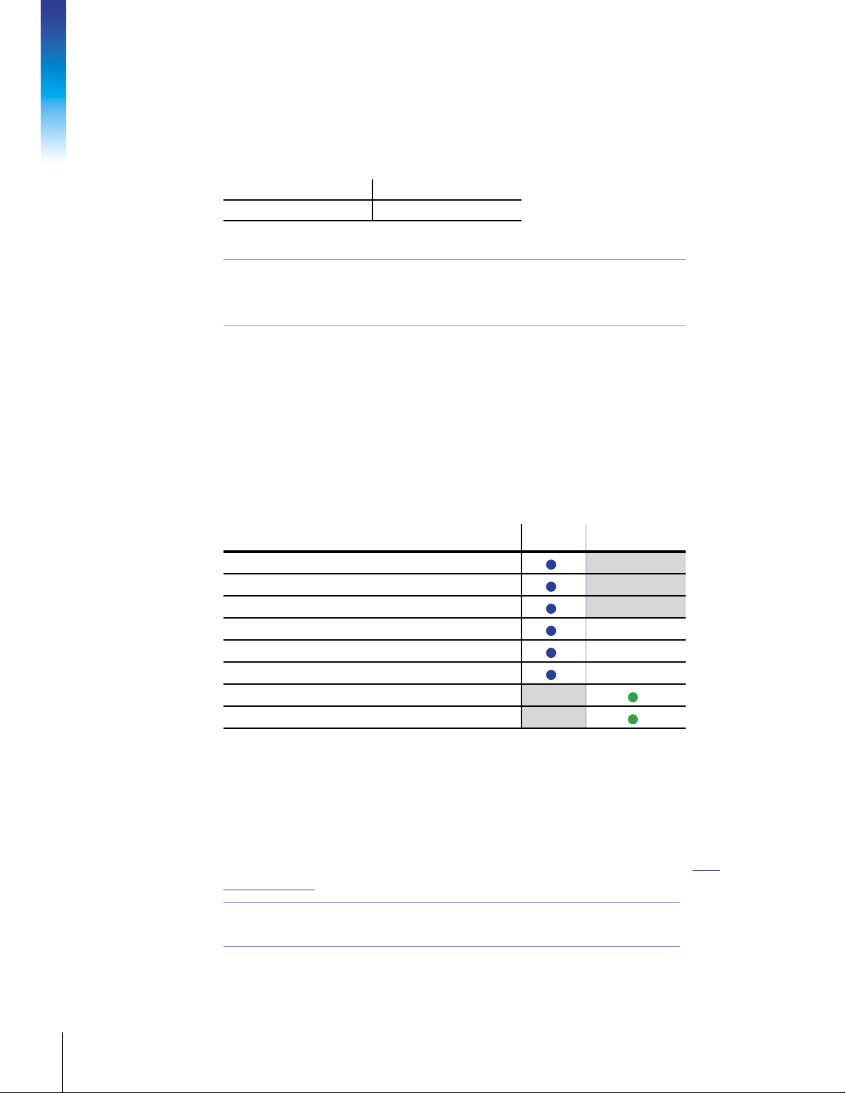
Table 2-6 Site Preparation—Standard and Optional Items
2. Pre-Installation Checklist
Item Standard Accessory / Option
Control Software—iC IR
Power Supply with country-specific AC power cable
USB cable
Funnel
Small flat-head screwdriver for gain adjustment
Choice of appropriate sampling technology
Stabilization Foot (for use with Mirror Conduit to provide stability)
Control computer (iC IR workstation PC)
[ ] Computer Specifications
When a computer is ordered with the system, the iC IR software is preloaded. If you plan to
purchase a new computer or use an existing one, it must meet minimum specifications that
METTLER TOLEDO recommends in the computer specifications listed in the “iC Software
Computer Specifications Guide.” Access this guide from the METTLER TOLEDO website: http:/
/www.mt.com/iC.
MK-PB-0114-AC Rev A 14
METTLER TOLEDO
Note:
Minimum specifications are listed in the “iC Software Computer
Specifications Guide” and also in the “iC IR Installation Guide.”
Page 15
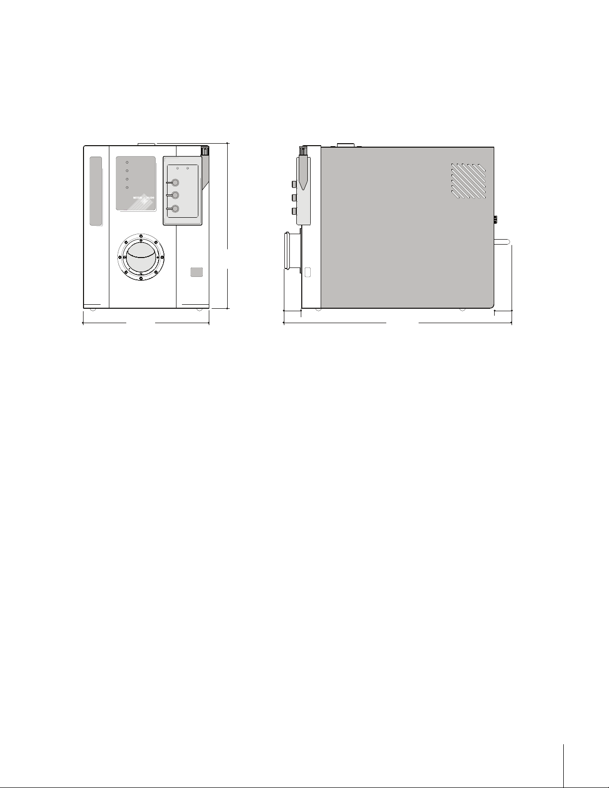
System Dimensions
The diagram in this section show the dimensions of the ReactIR 45m base unit. Allow
additional space for the sampling technology and control computer.
™
ReactIR
POWER
SCAN
MCT OK
TEMP OK
213 mm
[
8.4 in
P1 P2
ACC
RTD 2
RTD 1
279 mm
[
]
11 in
45m
28 mm
[
1.1 in
]
45m
]
381 mm
[
15 in
]
28 mm
[
1.1 in
]
Figure 2-1 ReactIR 45m base unit
METTLER TOLEDO
15ReactIR™ 45m Hardware Manual
Page 16

2. Pre-Installation Checklist
MK-PB-0114-AC Rev A 16
METTLER TOLEDO
Page 17

Product Description
This chapter describes the ReactIR™ 45m and the possible system configurations. A ReactIR
45m system consists of a base unit and sampling technology along with iC IR™ software.
Designed to be simple and easy to use, the system comes in the following overall
configurations that differ by the type of DS sampling technology:
"Overview of the ReactIR 45m System"
"ReactIR 45m System Diagram"
"ReactIR 45m Sampling Technology Configurations"
Overview of the ReactIR 45m System
ReactIR 45m is an FTIR-based, high performance, in situ reaction analysis system designed
specifically for the chemist and chemical engineer who require the highest level of precision
for kinetic studies and quantitative analysis. It provides real-time information on the effect of
changing reaction conditions such as solvent, catalyst, temperature, and reagent addition
rate, saving valuable resources. Based on the information provided by ReactIR 45m,
scientists are able to correlate, in real time, the impact of varying reaction conditions to
reaction performance—dramatically reducing development time.
3
Valuable characteristics of the ReactIR 45m system include:
Ergonomics—No obstruction to daily workflow, easy to monitor every reaction
Minimal purge—Improved data quality without external requirements/costs.
No alignment (FiberConduit only)—Highest quality data assurance without user input.
Minimal alignment in case of Mirror Conduits.
Plug-n-Play sampling—Reproducible measurements
Enhanced understanding of chemistry—Monitor reaction temperature simultaneously
with chemical changes
Note: Sensor sampling technology interfaces are sold separately.
Standard items included with the ReactIR 45m base unit are:
24-hour cooling capacity, Mercury Cadmium Telluride (MCT) detecor
iC IR 4.3 or later software version
USB communications cable
Power Supply with country-specific power cord
Funnel, small flat-head screwdriver
Purge tubing and connectors
Not included but necessary for routine operation are,
Workstation—Laptop or Desktop
METTLER TOLEDO
17ReactIR™ 45m Hardware Manual
Page 18
Sampling Technology: DS AgX Fiber Probe, DS Micro Flow Cell, K4 MirrorConduit/
Sentinel, or K6 MirrorConduit/16 mm Probe, DS Fiber-to-Sentinel, DS Fiber-to-Gas Cell
(MTPN available upon request)
One Year System Warranty (includes standard sampling technologies) purchased with
system). System warranty ends one year after installation or fifteen months after
shipment. Refer to page 93 for detailed warranty packages.
A ReactIR 45m system uses METTLER TOLEDO proprietary software, iC IR, to assure infrared
data collection and analysis possible without the need for an expert. iC IR is the result of many
years of evolution through valuable customer feedback that offers powerful reaction analysis
functions with an easy-to-use user interface. As a wizard-based application, iC IR guides you
through the experience of collecting, analyzing, and visualizing data for real time insight into
your chemistry. In essence, iC IR allows chemists to focus on solving chemistry problems
instead of instrumentation and analysis procedures.
See Chapter 4, “Safety” for safety-related information.
Definition of Terms
Refer to Appendix B on page 103 for the terms used throughout this manual and in the control
3. Product Description
software for a ReactIR 45m system.
This manual uses DS to refer to either DS or DST sampling technology.
DS is an abbreviation for D Sub-miniature, which describes the D-shaped
Note:
connector at the end of the sampling technology that connects to the
ReactIR 45m base unit. The DS or DST designation refers to the design
of the probe tip.
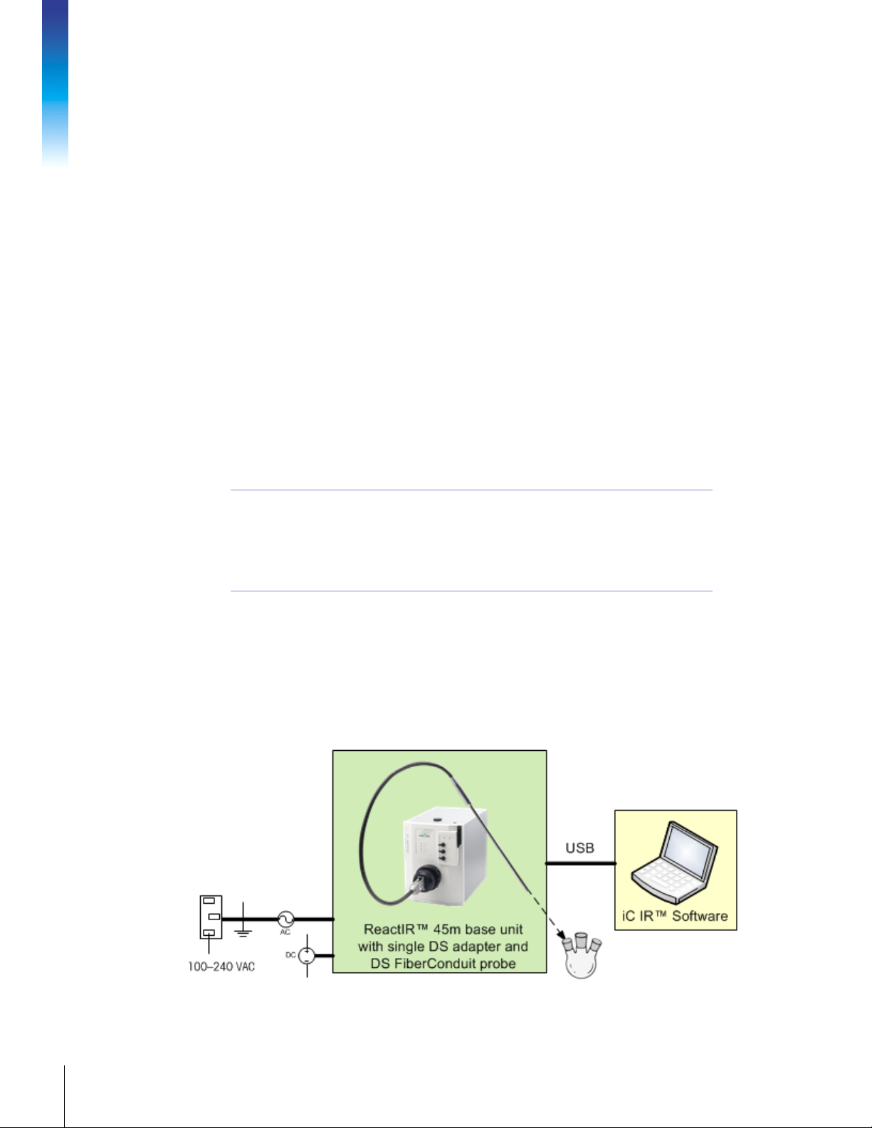
ReactIR 45m System Diagram
The diagram below identifies the components necessary to build up a ReactIR 45m system,
essentially what hardware the customer purchases from METTLER TOLEDO according to
specifications to install and implement the system. Components include the base unit,
computer, communication cable, power cable, and sampling technology.
Figure 3-1 ReactIR 45m system diagram
MK-PB-0114-AC Rev A 18
METTLER TOLEDO
Page 19

The Table 3-1 describes the internal components of a ReactIR 45m base unit: We include the
definitions for an understanding of the components that METTLER TOLEDO representatives
discuss with you during initial training, follow-up service or preventive maintenance. By
design, the ReactIR 45m will not require the user to know the location for alignment or
replacement of these components.
Table 3-1 ReactIR 45m Internal Components
MCT Detector Senses the amount of infrared radiation after passing through a sample. Includes a
detector preamp. Requires liquid nitrogen in the dewar to be operational. (1 L
capacity)
Detector Preamp Electronic board that assists the detector in reaching maximum operating
performance. User adjustment may be necessary when changing sampling
technology, for example from DS FiberConduit Probe to DS Micro Flow Cell or K4/K6
Mirror Conduit.
IR Source Supplies the infrared radiation to the sample
Midget Modulator Mechanical device that affords full spectrum infrared measurements of high
sensitivity in a shorter period of time than traditional dispersive spectroscopy
methods. Also known as the interferometer or heart of the Fourier Transform Infrared
(FTIR) measurement. Produces source radiation specific to FTIR technology.
Interferometer Control
Board Module (ICBM)
Power supplies Supplies electrical power to internal ReactIR 45m components.
Laser Class 1 InGa/AsP/InP laser diode that is an integral component of the modulator.
Circuit board for controlling specific devices related to the interferometer
(modulator).
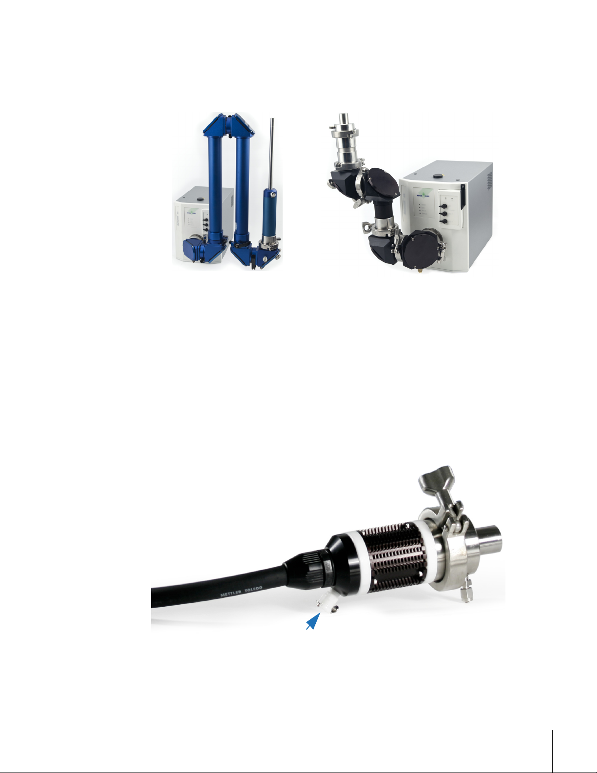
ReactIR 45m Sampling Technology Configurations
This section describes the sampling technology options available with ReactIR 45m.
"DS FiberConduit Probe"
"DS Micro Flow Cell"
"DS Fiber-to-Sentinel"
"DS Fiber-to-Gas Cell"
"K4 Mirror Conduit/Sentinel"
"K6 Mirror Conduit/16 mm Probe"
Please refer to the “ReactIR Sampling Technology Guide” for details on specific DS and
conduit technologies.
DS FiberConduit Probe
DS FiberConduit Probe systems are suitable for monitoring chemistry in a reaction vessel of
the customers' choice by insertion of the probe into the liquid-based reaction medium. This
ReactIR 45m configuration requires a DS Optical Interface Module (sold separately) in
addition to the DS FiberConduit probe. Temperature monitoring of the reaction mixture is
optional with a DS Optical Interface Module—RTD ready (sold separately).
METTLER TOLEDO
19ReactIR™ 45m Hardware Manual
Page 20
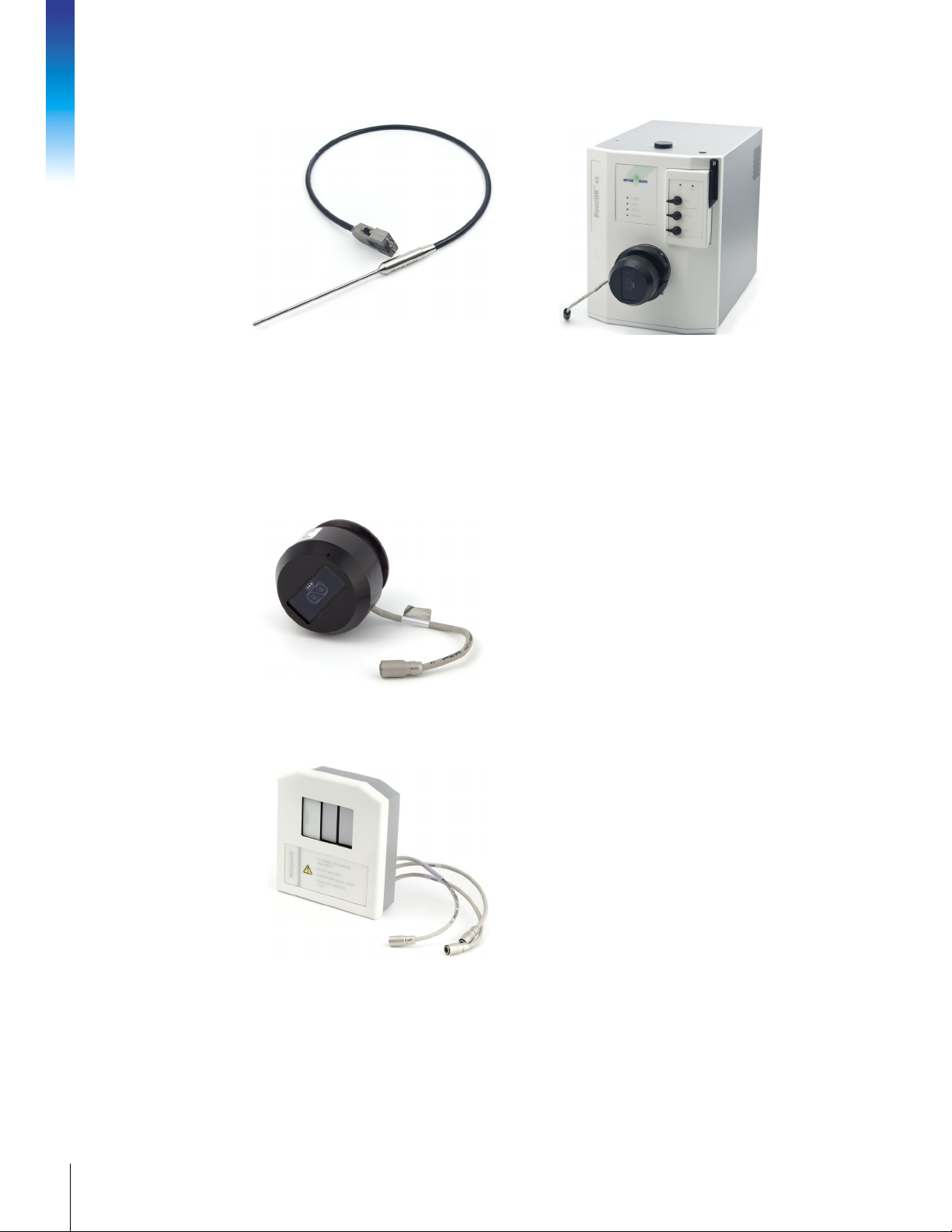
Figure 3-1 ReactIR 45m base unit with Single Optical Interface module (RTD option shown) for DS fiber
Optical Interface Modules
A single or multiple Optical Interface Module attaches to the SIM flange on the front of a the
ReactIR 45m base unit to connect to a DS fiber or DS Micro Flow Cell sampling technology.
Single Optical Interface
3. Product Description
Figure 3-2 Single Optical Interface Module (with RTD cable)
DS MultiplexIR
sampling technology
The figure below shows a Single Optical Interface
module with the optional Resistive Temperature
Device (RTD) cable.
ReactIR 45m can control two DS FiberConduit
probes with the optional MultiplexIR Optical
Interface module. The module includes RTD
technology for monitoring reaction temperature at
each probe.
MK-PB-0114-AC Rev A 20
METTLER TOLEDO
A MultiplexIR system monitors two different or
similar chemical reactions at the same time.
Figure 3-3 MultiplexIR for dual probe configuration
Figure 3-4 shows the MultiplexIR Optical Interface Module connected to the base unit with
two fiber probes.
Page 21
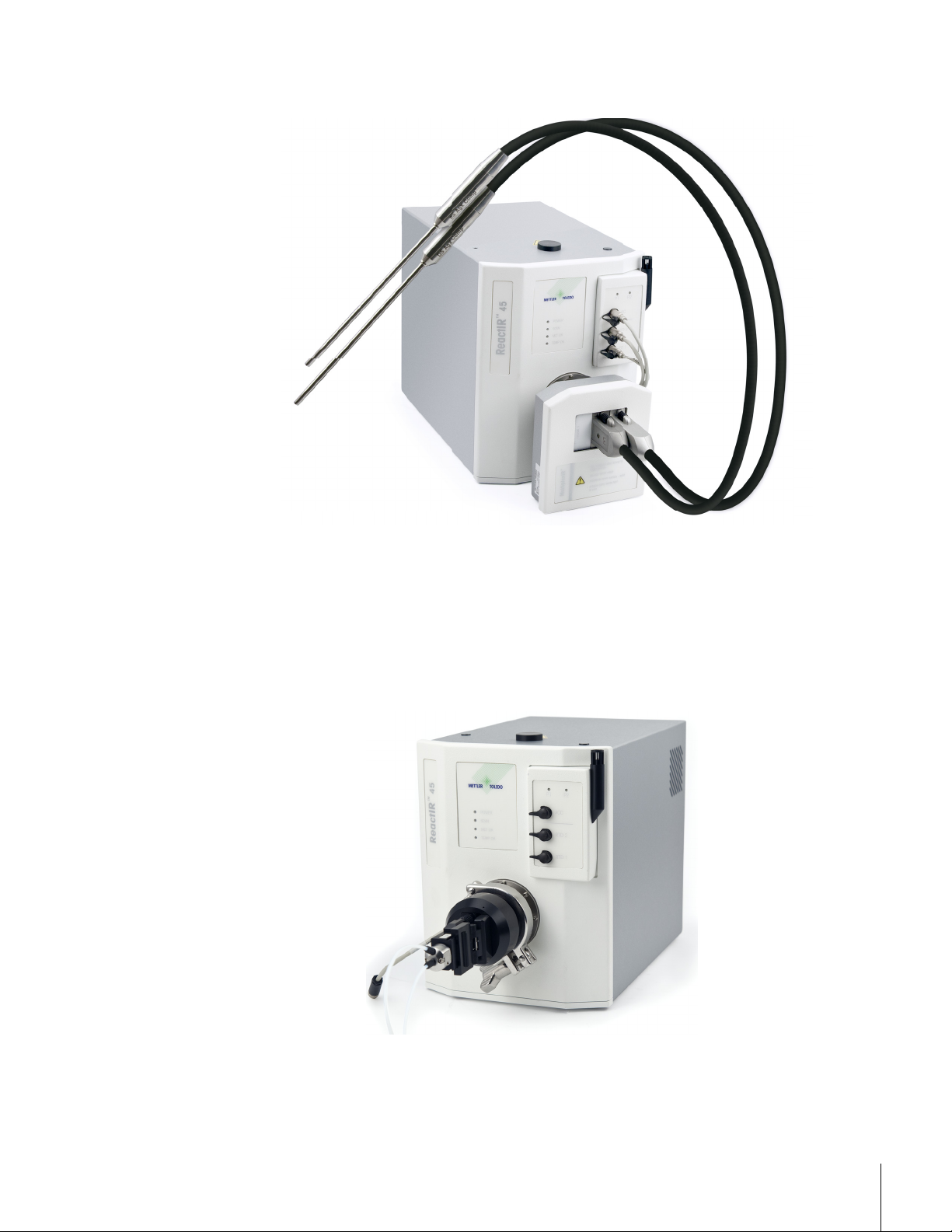
Figure 3-4 ReactIR 45m base unit with DS MultiplexIR Optical Interface Module and two fiber probes
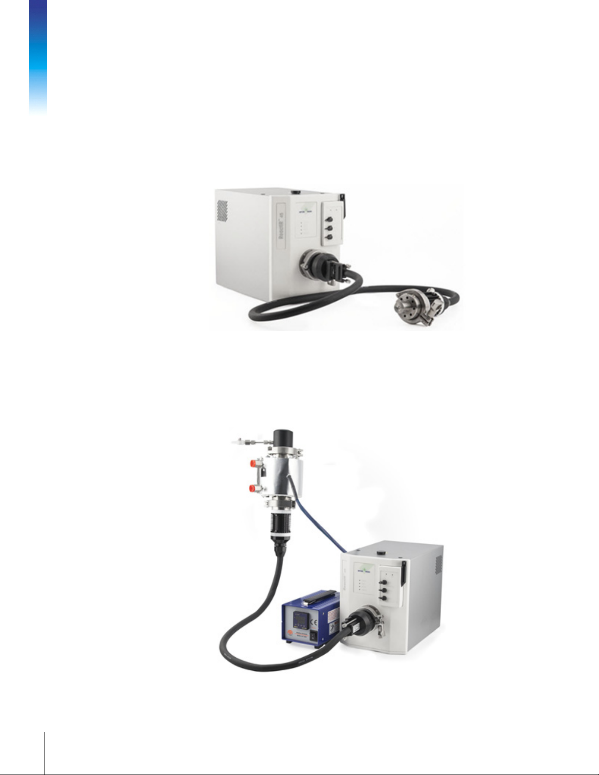
DS Micro Flow Cell
DS Micro Flow Cell systems are suitable for users who elect to flow their reaction chemistry
through a specially designed cell to monitor chemical changes. Monitoring and control of the
flow cell head temperature is available. A DS single optical interface module is required to
interface the DS Micro Flow Cell in this ReactIR 45m configuration.
Figure 3-5 ReactIR 45m base unit with DS Micro Flow Cell (heated)
Figure 3-5 shows the heated model DS Micro Flow Cell which includes a heater controller
and power supply (not shown).
METTLER TOLEDO
21ReactIR™ 45m Hardware Manual
Page 22
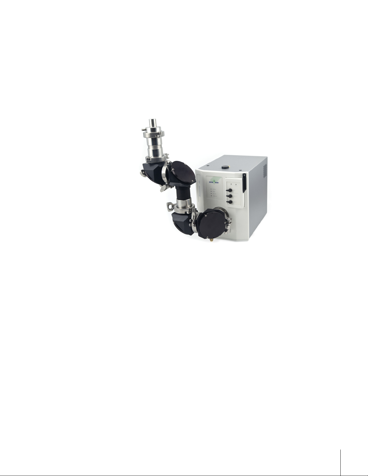
DS Fiber-to-Sentinel
A DS Fiber-to-Sentinel configuration is designed for customers who have a need to monitor
chemistry in high pressure autoclaves, large volume circulation loops, or specialty reaction
vessels. Designed for interfacing with the Sentinel probe, which is capable of withstanding
higher temperature and pressure reaction conditions than DS fiber probes. In addition, the
spectral region extends to 4000 wavenumbers versus the 2800 wavenumber upper limit of
the fiber probe. This ReactIR 45m configuration requires a DS single optical interface module.
Temperature monitoring of the reaction mixture is unavailable with this configuration.
3. Product Description
Figure 3-6 ReactIR 45m base unit with DS Fiber-to-Sentinel sampling technology
DS Fiber-to-Gas Cell
Customers who want to monitor gas phase reactions or head space can choose a DS Fiberto-Gas Cell option in combination with a ReactIR 45m base unit. This type of configuration
requires a DS single optical interface for integration of the DS fiber to gas cell.
MK-PB-0114-AC Rev A 22
METTLER TOLEDO
Figure 3-7 ReactIR 45m base unit with DS Fiber-to-Gas Cell sampling technology
Page 23
K4 Mirror Conduit/Sentinel
K4 Mirror Conduit/Sentinel systems monitor liquid chemistry in a specialty reaction vessel or
flow cell available from METTLER TOLEDO. Manipulate the K4 conduit to connect to the
Sentinel probe that is mounted in the specialty vessel. The Sentinel probe offers users the
capability to monitor higher temperature and pressure reaction conditions than DS fiber
probes. In addition, the spectral region extends to 4000 wavenumber versus the 2800
wavenumber upper limit of the fiber probe.
Temperature monitoring of the reaction mixture is unavailable with this configuration.
Figure 3-8 ReactIR 45m base unit with K4 Mirror Conduit sampling technology
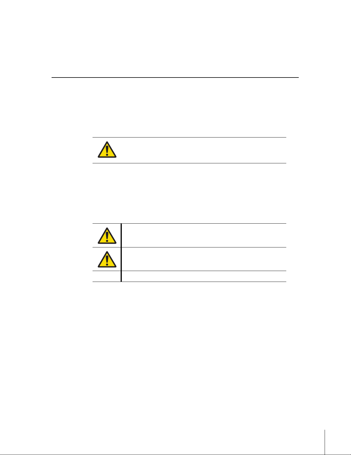
K6 Mirror Conduit/16 mm Probe
K6 Mirror Conduit/16mm probe systems monitor chemistry in a reaction vessel of the
customers' choice by inserting the probe into the liquid-based reaction medium. The 16 mm
probe offers users the capability to monitor higher temperature and pressure reaction
conditions than DS fiber probes. In addition, the spectral region extends to 4000
wavenumber versus the 2800 wavenumber upper limit of the fiber probe.
Temperature monitoring of the reaction mixture is unavailable with this configuration.
METTLER TOLEDO
23ReactIR™ 45m Hardware Manual
Page 24
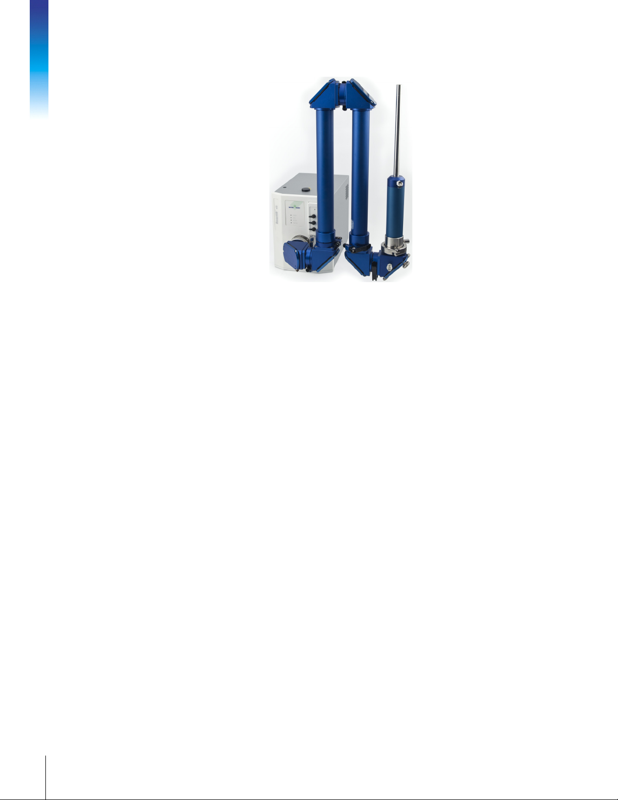
Figure 3-9 ReactIR 45m base unit with K6 Mirror Conduit sampling technology
3. Product Description
MK-PB-0114-AC Rev A 24
METTLER TOLEDO
Page 25
Safety
4
Per the ISO 9001 procedures followed at METTLER TOLEDO, the ReactIR 45m system
adheres to applicable regulations and standards in the area of intended use. Requirements
for compliance with local regulations may be different. The end user of the equipment is
responsible for compliance with all local, corporate, or other applicable regulations.
WARNING—Use of this product in a manner other than described in
this manual may result in serious injury, damage to equipment, and/or
void the warranty of the system.
Warnings, Cautions, and Notes
Three levels of information relate to equipment and user safety. To help you recognize
information, the following symbols appear throughout this manual. Please pay particular
attention to the sections marked by these symbols.
Table 4-1 Warnings, Cautions, and Notes
Note: Information that should receive your attention.
Product Safety
ReactIR 45m systems comply with the directives and laser classifications described below.
Compliance
EMC Directive 2004/108/EC
IEC 61326-1: Electrical Equipment for Measurement, Control and Laboratory Use
Low Voltage Directive 2006/95/IEC
EN61010-1: Safety requirements for electrical equipment for measurement, control,
and laboratory use
Harmonized Standards:
EN61326-1:2006, EN61000-3-2:2008, EN61000-3-3:2006, EN61010-1:2001
Caution—Important information that tells you how to prevent damage
to equipment, or to avoid a situation that may cause minor injury.
WARNING—Important safety information—Failure to observe the
warning may result in serious personal injury or equipment damage.
METTLER TOLEDO
25ReactIR™ 45m Hardware Manual
Page 26
Laser Classification
All ReactIR 45m instruments are in compliance with the U.S. Department of Health and
Human Services (DHHS) Radiation Performance and in accordance with International
Standards.
Class 1 Laser Product
Compliant with DHHS 21 CFR 1040.10 and 1040.11
except for deviations per Laser Notice 50
4. Safety
Grounding the Power Supply
Operational Safety
and
Compliant with IEC 60825-1
WARNING—Make sure to plug the power cable supplied with the
ReactIR 45m system into power supply outlets that are grounded. A
technical fault could otherwise result in death or serious injury.
Connection of cables
Caution—Connect all cables (power and communications) of the
ReactIR 45m system to their respective inputs and outputs before you
switch on the system. Do not disconnect any cables while the system
is in operation as this may cause damage to internal electrical
components.
Handling Liquid Nitrogen
MK-PB-0114-AC Rev A 26
METTLER TOLEDO
Caution—Liquid Nitrogen is used with the ReactIR 45m system to cool
the MCT detector for optimum detector performance. Liquid Nitrogen will
cause severe burns to exposed skin. Ensure use of proper clothing
(gloves) and eye protection before handling Liquid Nitrogen.
NOTE: A caution label is located on the top of the ReactIR 45m base
unit, next to the Liquid Nitrogen fill port.
Liquid Nitrogen “Blow Off”
Caution—When filling the MCT detector with Liquid Nitrogen there is a
chance that the Liquid Nitrogen may “Blow Off” once sufficient pressure
is reached inside the detector cooling chamber. It is recommended to
add Liquid Nitrogen slowly to allow sufficient time for entrained
pressure to release from the cooling chamber and prevent “Blow Off.”
Page 27
Cold Surfaces (Liquid Nitrogen Spills)
Caution—Spills will most likely occur when filling the MCT cooling
chamber with Liquid Nitrogen. Normal Liquid Nitrogen spillage (i.e.
Blow Off) will not damage components of the ReactIR 45m system,
BUT will create COLD surfaces. Avoid touching these cold surfaces
without proper protective clothing. These cold surfaces typically warm
to room temperature within a few minutes (~15 minutes).
Lithium Battery
Caution—The ReactIR 45m base unit includes a CR-2032 3 V
manganese dioxide lithium coin battery for the real-time clock.
Battery is not user-replaceable.
Service
Caution—Never open the enclosure of the ReactIR 45m system or any
of its components. These items are serviced only by a qualified
METTLER TOLEDO AutoChem Service Engineer.
General Caution
System Handling
Disconnect the power supply.
Move the ReactIR 45m base unit in an upright position to avoid spilling any amount of
the liquid nitrogen remaining in the MCT detector dewar.
When moving the ReactIR 45m system, it is highly recommended to use a cart or similar
type device. The system can be hand-carried by using the integrated handle on the rear
of the system. The ReactIR 45m does not have a front sampling attachment port, so lift
using the handle in the rear and support the front from the underside of the enclosure.
DO NOT hand-carry the base unit with the fiber optic or mirror conduit sampling
technology attached to the system. Remove the sampling technology first before moving
the unit.
DO NOT move the system with the conduit attached by using a cart or similar device.
Remove the sampling technology first before moving the unit.
Exclude the following environmental influences:
temperatures below 19 °C and above 40 °C
powerful vibrations
direct sunlight
atmospheric humidity greater than 60%
powerful electric or magnetic fields
Caution—The system can be awkward when handling. Follow the basic
safety steps outlined below
METTLER TOLEDO
27ReactIR™ 45m Hardware Manual
Page 28

4. Safety
ONLY lift the system using the handle in the rear while supporing the front underside of
the ReactIR 45m base unit. Lifting the unit in any other manner may cause damage to
the system or personal injury should the cover unexpectedly become detached.
Position the ReactIR 45m base unit to enable easy disconnection of the DC power cable.
MK-PB-0114-AC Rev A 28
METTLER TOLEDO
Page 29

Specifications
This chapter provides specifications for the ReactIR 45m system in the following sections:
“ReactIR 45m Base Unit” on page 29
“Purge” on page 30
“iC IR Computer Specifications” on page 30
Specifications include those provided by METTLER TOLEDO and those that are your
responsibility as the customer.
Manufacturer Name—Mettler-Toledo AutoChem, Inc.
Manufacturer’s Address—7075 Samuel Morse Drive Columbia, Maryland USA 21046
Product—ReactIR™
Model No—45m
Trademark—METTLER TOLEDO
Intended Use—The use of this product is to provide unattended, in situ data collection and
simultaneous data analysis of chemical reactions. This product is designed to be used in a
ventilated fume hood. Alternatively, this system can be used on a bench top with the flexible
fiber optic conduit positioned inside the fume hood where the reactor is located.
5
ReactIR 45m Base Unit
Materials of construction:
Enclosure Aluminum Alloy 5052-H32
Enclosure finish Iridite and Paint Polane-T
Labels Poly carbonate
Electrical:
Power AC: 100–240 VAC ±7%, 50/60 Hz, 2.0 A
Power supply (provided) Rated DC input: ±12 VDC, 2.5 A and 13.6 VDC, 6 A
Environmental conditions:
Temperature Range Operating: 19 °C to 25 °C [66 °F to 77 °F]
Humidity Ambient: <60% non-condensing
Table 5-1 ReactIR 45m System Specifications
Mini Fuse: 5 A, fast acting, internal
BATTERY: CR-2032 3V manganese dioxide lithium coin battery for real-
time clock.
Ambient (max): 40 °C [104 °F] (invalidates performance specification)
IMPORTANT—System should not be placed directly under an air duct or vent that
would expose the base unit to direct airflow and extreme temperature ramps.
METTLER TOLEDO
29ReactIR™ 45m Hardware Manual
Page 30

Table 5-1 ReactIR 45m System Specifications (continued)
Miscellaneous specifications:
Communications 10 m [32.8 ft], USB 2.0
Detector 24-Hour Cooling Capacity, Mercury Cadmium Telluride (MCT) detector
Size and weight:
Dimensions (H x W x D)
Refer to drawing on page 15.
Weight 16.0 kg [35.3 lb]
The sampling technology selected for the ReactIR 45m system determines additional system
specifications such as the optical range for the instrument. Please refer to the “Sampling
Technology Guide” in your Hardware Documentation Portfolio (or get the latest document
from the AutoChem Customer Community website:
279 mm x 213 mm x 381 mm [11 in x 8.4 in x 15 in]
https://community.autochem.mt.com).
5. Specifications
Purge
The ReactIR 45m base unit requires a purge. In addition, the ReactIR Fiber-to-Sentinel, Fiberto-Gas Cell, and Mirror Conduit sampling technologies also require clean, dry, instrument
quality air for purge. If you use the DS Fiber-to-Sentinel (page 21) or the Mirror Conduit
(page 23) sampling technologies, a purge connection is required. Clean, dry, instrument
grade air, nitrogen, or equivalent gas is recommended. Quality of the air or gas supply must
meet the specifications of the American National Standards Institute/Instrument Society of
America (ANSI/ISA) S7.0.01-1996 Quality Standard for Instrument Air.
Pressure 0.69 bar [10 psi]
Flow Rate 4.7 LPM [10 SCFH]
Have a dew point at least 10 °C [18 °F] lower than the minimum temperature to which
any part of the system will be exposed.
Contain less than 1 ppm total oil or hydrocarbons.
Contain less than 1 ppm particulates at a maximum size of three (3) microns.
Be free of any corrosive contaminants and flammable or toxic hazardous gases.
iC IR Computer Specifications
Table 5-2 Purge Specifications
MK-PB-0114-AC Rev A 30
METTLER TOLEDO
When a computer is ordered with the system, the iC IR software is preloaded. If you plan to
purchase a new computer or use an existing one, it must meet minimum specifications that
METTLER TOLEDO recommends in the “iC Software Computer Specifications Guide.” Access
this guide from the METTLER TOLEDO website: http://www.mt.com/iC.
Note:
Minimum specifications are listed in the “iC Software Computer
Specifications Guide” and also in the “iC IR Installation Guide.”
Page 31

Installation
This chapter provides procedures on how to install or reinstall a ReactIR™ 45m system.
Note:
6
METTLER TOLEDO offers one of the following ServicePac options related to
installation and system commissioning:
IPac StarterPac—(Basic Installation) The ReactIR 45m IPac StarterPac is
designed for customers in the Academia, Government, Chemical, and
Polymer Industries needing professional installation by a trained and
authorized METTLER TOLEDO Field Service Engineer (FSE). These customers
have no internal requirements for instrument Calibration/Validation to a
certified NIST Polystyrene Standard for data accuracy. Therefore, the IPac
StarterPac does not include Calibration/Validation using the DS IPA Module.
The customer must purchase the IPac QualityPac for this additional
service.For additional information, see page 99.
IPac QualityPac—The ReactIR 45m IPac QualityPac is designed for
customers in the Pharmaceutical, Biotech, and Food Industries needing
objective evidence and records to satisfy quality requirements of their
organization. These customers have internal requirements for instrument
Calibration Validation to a certified NIST Polystyrene Standard by a trained
and authorized METTLER TOLEDO FSE to ensure data accuracy. For
additional information, see page 100.
Instrument installation and commissioning includes one of the METTLER TOLEDO service
package offerings performed by a METTLER TOLEDO FSE, plus site preparation performed by
the end user. The scope of the installation service includes:
Site requirements verification
Equipment inspection and order validation
System installation and startup
Acceptance Criteria
The IPac StarterPac or IPac QualityPac requires approval signatures from the METTLER
TOLEDO AutoChem FSE and your organization’s ‘Responsible User.’
Note:
Place the signed ServicePac document in a readily accessible location
for reference during system service or maintenance.
An annual Preventive Maintenance service is available for ongoing
instrument validation and calibration (see page 93).
METTLER TOLEDO
31ReactIR™ 45m Hardware Manual
Page 32

Site Preparation (Customer Responsibility)
The ReactIR 45m system pre-installation details are sent to the end user when initial shipment
of the system is scheduled. Refer to Chapter 2, “Pre-Installation Checklist.” Permanent or
temporary installation of a ReactIR 45m system must include the following:
Adequate space and preparation in area of intended use
Electrical supply
Air supply
Environment preparation
A METTLER TOLEDO Field Service Engineer will set up and install the ReactIR 45m system
system after verifying site preparation. Site preparation requirements must be completed
before the engineer arrives on site. Permanent or temporary installation for a ReactIR 45m
6. Installation
must include the steps described in the next section.
Installation Instructions
This section describes the procedures for installing the ReactIR 45m.
“1. Confirm Site Readiness” on page 32
“2. Verify Hardware Configuration/Order Validation” on page 32
“3. Confirm Hardware Service Agreement and Software Version” on page 33
“4. Install iC IR Software” on page 34
“5. Perform Initial Setup and Establish System Connections” on page 34
“6. Establish Sampling Technology Conduit Purge (if applicable)” on page 41
“7. Apply Power to System and Verify LEDs” on page 42
“8. Launch Software” on page 42
“9. Configure ReactIR 45m Instrument in Control Software” on page 44
1. Confirm Site Readiness
A METTLER TOLEDO Field Service Engineer (FSE) checks the ReactIR 45m installation site in
accordance with the product requirements and completes the first section of the ServicePac
offering—IPac StarterPac or IPac QualityPac. The end user must ensure the site is ready prior
to arrival of the FSE based on the “Pre-Installation Checklist” information in Chapter 2.
Proceed to the next step only after confirming the site is ready.
2. Verify Hardware Configuration/Order Validation
A METTLER TOLEDO Field Service Engineer (FSE) will complete the ReactIR 45m ServicePac
document after confirmation that the site has been properly prepared for installation. In
addition to verifying the site preparation and receipt of ordered parts (including service
agreements/programs), the ServicePac document covers all aspects of the final stages of
system installation.
MK-PB-0114-AC Rev A 32
METTLER TOLEDO
Page 33

There are a variety of hardware configuration options based on the type of sampling
technology.
Sampling Technology
Sampling Technology components are purchased separately and include options described
in Chapter 3, “Product Description” starting on page 19.
The FSE will complete the sampling technology section of the ServicePac installation
document with the information specific to the type of technology ordered. FSE will enter N/A
(not applicable) for sections that do not apply to the customer order as well as record the
'wetted materials' and 'pressure/temperature' specifications for the sampling technology, in
accordance with the supplied documentation. Any items that are missing will be entered into
the non-conformances section of the form with an action plan to resolve.
Optional Hardware
Optional components are the control computer and the Instrument Performance Assurance
(IPA) module.
Software
ReactIR 45m control software is iC IR.
Optional Software
Optional software includes iC Quant, ConcIRT Pro, iC Kinetics, iC Data Share, and iC Data
Center.
Documentation
This ReactIR 45m Hardware Manual is included in a Hardware Documentation Portfolio
delivered on a separate Documentation CD with the instrument. During installation, the FSE
installs the portfolio on the control computer.
A software Documentation Portfolio accessible through the iC IR software contains iC software
publications. Access the portfolio from Help > Show Documentation Portfolio.
The latest ReactIR 45m and iC IR software documents are on the AutoChem Customer
Community website: https://community.autochem.mt.com.
3. Confirm Hardware Service Agreement and Software Version
The FSE will use the appropriate sections of the ServicePac document to confirm the hardware
service agreement with expiration date and software that was ordered is contained in the
shipment.
METTLER TOLEDO
33ReactIR™ 45m Hardware Manual
Page 34

4. Install iC IR Software
Before setting up the communications between a computer and the ReactIR 45m base unit,
the FSE will verify that the PC meets the specifications under “iC IR Computer Specifications”
on page 30. The FSE will need the iC IR Instrument License, included with your order, to
operate the ReactIR 45m instrument.
1. Insert the iC IR installation CD in the PC and click Install iC IR #.# (setup.exe) from the
welcome page.
2. Install the software according to the wizard-guided steps.
Refer to the “iC IR Installation Guide” for additional installation information on
administering preferences, licensing, and sharing data between iC/iControl software
applications.
6. Installation
5. Perform Initial Setup and Establish System Connections
The FSE will complete the System Connections in the appropriate ServicePac document while
progressing through these instructions to ensure all ReactIR system hardware is in the proper
location with connectivity to utilities, computer, and sampling technology. Users should
follow and learn the steps taken by the FSE for future reference in the event of relocating the
system. Section F and G are procedures that all users should learn for routine operation.
Initial setup and system connections include the following:
“A. Locate ReactIR 45m Base Unit and Computer at Site” on page 34
“B. Connect power” on page 35
“C. Connect USB Cable” on page 36
“D. Connect System Purge” on page 37
“E. Remove Shipping Constraint from MCT Fill Port” on page 37
“F. Fill the Detector Dewar” on page 37
“G. Connect Sampling Technology” on page 39
Note:
DO NOT proceed with the 'System Start Up' section until all applicable
check boxes are complete.
MK-PB-0114-AC Rev A 34
METTLER TOLEDO
A. Locate ReactIR 45m Base Unit and Computer at Site
1. Place the base unit in the predetermined customer location on a benchtop, in a hood,
or area of intended use per the site preparation requirements.
2. In addition, place the computer in a suitable work location that allows connectivity
through a USB cable.
3. Position the base unit and power supply to enable easy access to the ON/OFF switch.
Page 35

B. Connect power
The power connection (A) is at the back of the ReactIR 45m base unit.
A
Figure 6-1 Power connection at back panel of ReactIR 45m
1. Ensure that your power supply meets the specifications under the electrical
specifications section on page 29.
2. Connect the supplied power cord to the unique connector (A) on the back panel of the
ReactIR 45m base unit.
3. Connect the opposite end into the power supply.
4. Connect the AC power cord to the power supply and an AC outlet or power strip/surge
protector.
5. Connect power to the computer.
METTLER TOLEDO
35ReactIR™ 45m Hardware Manual
Page 36

C. Connect USB Cable
1. Connect the supplied USB communications cable to the USB connector (B) on the back
6. Installation
panel of the ReactIR 45m base unit (Figure 6-2).
B
Figure 6-2 ReactIR 45m—Communications cable connection at back panel
2. Connect the opposite end of the USB communications cable to any available USB port
on the computer where the iC IR software is installed.
3. If the Found New Hardware wizard appears, point to the folder where the drivers were
installed during software installation.
Default installation folder on Windows XP: Program Files > METTLER TOLEDO > iC IR
#.# >Installation folder > FTIR Device Driver >icbm.
Default installation folder on Windows 7:
C:\Program Files (x86)\METTLER TOLEDO\iC IR #.#\FTIR Device Driver\icbm
MK-PB-0114-AC Rev A 36
METTLER TOLEDO
Page 37

D. Connect System Purge
The ReactIR 45m system requires purge with Instrument grade air, nitrogen, or equivalent
gas. Using the purge tubing and connector supplied by METTLER TOLEDO, establish the
purge connection on the rear panel of the ReactIR 45m at the location shown in Figure 6-3
at point (C). Perform this step prior to filling the MCT detector dewar with liquid nitrogen (see
next section).
C
Figure 6-3 Purge connection
E. Remove Shipping Constraint from MCT Fill Port
A ReactIR 45m base unit ships with restraining hardware for the MCT fill port. Remove this
hardware by twisting the locking nut counterclockwise. Save the locking nut for reuse if the
unit needs to be shipped for service in the future.
F. Fill the Detector Dewar
The highly sensitive MCT detector detects and analyzes component concentrations as low as
0.1 weight percent for strong infrared absorbers. To render the detector functional, you must
fill the MCT dewar with liquid nitrogen. The detector operates to maximum performance for
up to 24 hours without refilling.
Caution—Liquid Nitrogen must be handled in accordance with
applicable safety procedures. Liquid Nitrogen will cause severe burns
to exposed skin. Ensure use of proper clothing (gloves) and eye
protection before handling liquid Nitrogen.
NOTE: A caution label is located on the top of the ReactIR 45m base
unit, next to the Liquid Nitrogen fill port.
METTLER TOLEDO
37ReactIR™ 45m Hardware Manual
Page 38

1. Remove the plug from the top of the ReactIR 45m system and insert supplied funnel
6. Installation
2. Pour liquid nitrogen into funnel.
into the fill port.
Figure 6-4 Liquid nitrogen fill port on ReactIR 45m—Plug removed
MK-PB-0114-AC Rev A 38
METTLER TOLEDO
Figure 6-5 Filling Dewar with liquid nitrogen to cool the detector
a. Add several funnels full of liquid nitrogen.
Note:
b. After blow back subsides, add several more funnels full of liquid nitrogen.
c. Once liquid nitrogen spills from the top of the detector, replace the plug.
At some point the nitrogen may blow back, creating a jet of nitrogen
vapor and possibly liquid.
Page 39

G. Connect Sampling Technology
The standard Sample Interface Module (SIM) flange opening on the front of a ReactIR 45m
base unit requires a DS optical interface adapter for use with DS sampling technologies. Use
a Single or MultiplexIR (MUX) DS optical interface adapter to convert the standard SIM.
Figure 6-6 DS optical interface adapters—Single on left, MultiplexIR on right
1. Connect the DS optical interface (single or MultiplexIR) to the base unit and secure
using the clamp provided.
2. If applicable, connect the RTD cable to the RTD 1 or RTD 2 connector on the front of the
ReactIR 45m base unit. The single interface includes a single RTD cable and the
MultiplexIR interface includes two RTD cables.
3. Then, connect the DS sampling technology ordered with the unit to the DS optical
interface on the front panel of the ReactIR 45m, as described below. Go to the section
on page 41 for connection of K4 Conduit/Sentinel and K6 FiberConduit/16mm Probe.
4. (For MultiplexIR only) Connect the ACC cable to the ACC input on the front of the ReactIR
45m for MultiplexIR power.
DS Fiber Probe or Fiber-to-Sentinel
Figure 6-7 Connecting DS FiberConduit sampling technology to Single DS Optical Interface module
To install the FiberConduit probe sampling technology:
1. Orient the DS end of the probe with the retractable cover to the left, as shown on the DS
optical interface entry slot.
METTLER TOLEDO
39ReactIR™ 45m Hardware Manual
Page 40

2. Pull back on the retractable cover that exposes the optical connection and insert the end
3. Secure the sampling technology with the two knurled screws.
To install the Fiber-to-Sentinel sampling technology:
1. Orient the DS end with the retractable cover to the left, as shown on the DS optical
2. Pull back on the retractable cover that exposes the optical connection and insert the end
3. Secure the sampling technology with the two knurled screws.
4. Connect the Sentinel sensor to the opposite end of the FiberConduit, using clamp.
Fiber-to-Gas Cell
Follow the same procedure as for Fiber-to-Sentinel connections (step 1 on page 40 to
6. Installation
step 4).
DS Micro Flow Cell
into the DS SIM to align the unique connector.
interface entry slot.
into the DS SIM to align the unique connector.
Figure 6-8 Connecting DS Micro Flow Cell sampling technology
1. Orient the DS end with the retractable cover to the left, as shown on the DS optical
interface entry slot.
2. Pull back on the retractable cover that exposes the optical connection and insert the end
into the DS SIM to align the unique connector.
3. Secure the sampling technology with the two knurled screws.
MK-PB-0114-AC Rev A 40
METTLER TOLEDO
Page 41
K4 or K6 Mirror Conduit/Sentinel
The Mirror Conduit sampling technologies connect to the front Sample Interface module (SIM)
flange directly—no DS Optical Interface. Secure the connection using the clamp provided.
Figure 6-9 K6 or K4 Mirror Conduits connect directly to the SIM
1. Orient the open end of the conduit on the SIM flange of the base unit.
2. Secure the conduit sampling technology with the clamp provided.
3. System is ready for alignment.
6. Establish Sampling Technology Conduit Purge (if applicable)
If you use the K4, K6, Fiber-to Sentinel, or Fiber-to-Gas Cell sampling technologies, a purge
is required.
1. Attach a filtered, pressure-controlled air supply to the sampling technology using the
supplied purge tubing and connectors.
2. Set purge pressure to nominal
0.69 bar [10 psi]
and flow rate to
4.7 LPM [10 SCFH].
Figure 6-10 ReactIR 45m with DS Fiber-to-Sentinel sampling technology
41ReactIR™ 45m Hardware Manual
METTLER TOLEDO
Page 42

7. Apply Power to System and Verify LEDs
1. Press the power supply switch to the ‘on’ position to apply power to the ReactIR 45m
2. Verify the LED indicators on the front of the base unit indicate a fully functional system.
8. Launch Software
6. Installation
1. Confirm the iC IR software control computer is ON and the software launches.
system.
In a fully functional system, the Power LED is illuminated, the Scan LED is flashing, the
MCT OK LED is illuminated (dewar filled with liquid nitrogen), and the Temp OK LED is
illuminated when the modulator has reached an operating temperature of 42 °C
(approximately 30 minutes). Refer to “ReactIR 45m LED Indicators” on page 77 for
details. Details are also in the appropriate ServicePac document—IPac StarterPac or
IPac QualityPac.
To start the software, double-click the iC IR icon on the Windows desktop.
You will see the Start Page for iC IR software (Figure 6-11).
MK-PB-0114-AC Rev A 42
METTLER TOLEDO
Figure 6-11 iC IR Start Page
Page 43

If optional software is included with the order, confirm optional software add-ons
launch.
• iC Kinetics is a separate software application with its own Start Page.
Figure 6-12 Optional add-on software—iC Kinetics
• iC Quant and ConcIRT Pro appear as Data-to-Information (D2i) documents from the
iC IR Start Page.
Figure 6-13 Optional add-on software—iC Quant and ConcIRT Pro
• iC Data Share is an add-on to Excel available with an iCare subscription. The
software can be downloaded from the AutoChem Customer Community website.
Refer to Chapter 1, “Introduction” for information on iCare and the community
website.
• iC Data Center is a separate software application that serves as a monitoring and
central storage tool for data acquired by iC and iControl instruments.
METTLER TOLEDO
43ReactIR™ 45m Hardware Manual
Page 44
9. Configure ReactIR 45m Instrument in Control Software
The FSE will perform instrument configuration in iC IR software to reflect the hardware
configuration. Record the configuration settings in the appropriate ServicePac document.
1. Click Configure Instrument from the iC IR Start Page.
2. Set the following parameters to match the configuration of the ReactIR 45m, if not
6. Installation
already done at the factory.
MK-PB-0114-AC Rev A 44
METTLER TOLEDO
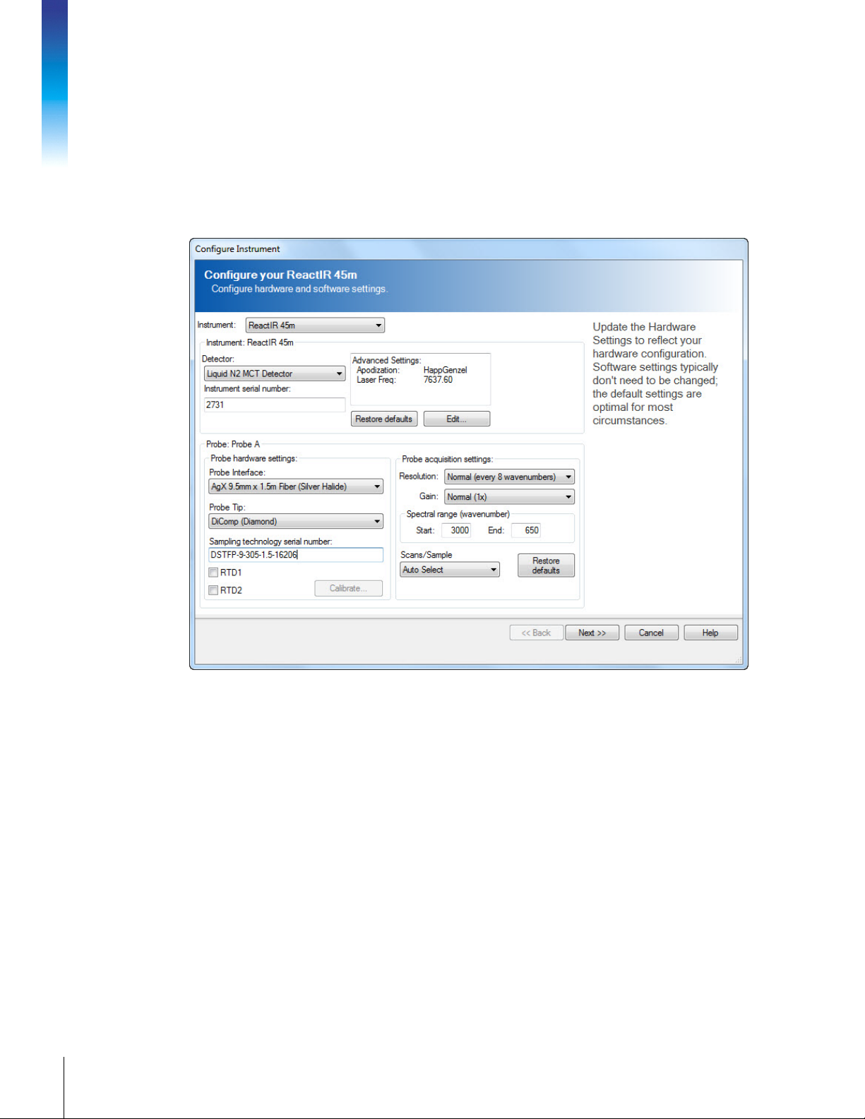
Figure 6-14 Configure Instrument wizard
• Instrument—Select ReactIR 45m
• Detector—Select the Liquid N2 MCT Detector.
• Instrument serial number—Type in the number from the label on the instrument
back panel.
• Probe Interface—Specify the type of DS FiberConduit or Mirror Conduit sampling
technology in use.
• Probe Tip—SiComp or DiComp
• Sampling technology serial number—Type in the number from the probe’s DS
connector or the Probe/Sentinel attached to a Mirror Conduit.
3. From the Advanced Settings section, the FSE will record the instrument firmware version
in the ServicePac document.
4. In the Probe acquisition settings section:
• Resolution—Normal (every 8 wavenumbers)
Page 45

• Gain—Normal (1x)
Note: Setting may require adjustment with multiple probes (MultiplexIR).
• Spectral range (wavenumber)—This value appears automatically, depending on
the sampling technology.
• Scans/Sample drop-down box, select Auto Select scans.
5. Accept the default for the remaining configuration settings.
Calibrating Resistive Temperature Device (RTD)
Below are the steps required to calibrate the sampling technology RTDs that are built-in DS
FiberConduit sampling technology probes. The FSE will use RTD test plugs or an external
calibrated temperature monitoring device such as a thermocouple to perform the two-point
calibration from the iC IR Configure Instrument page.
Note:
DS and DST Fiber probes support RTD monitoring—Fiber-to-Sentinel, Fiberto-Gas Cell, and K4/K6 Mirror Conduit technologies do not include an RTD.
1. Open the configure instrument wizard, select RTD 1 and click Calibrate to launch the
RTD calibration wizard.
Figure 6-15 Configure Instrument—Optional RTDs
2. Select the RTD1 row and highlight the RTD Device.
• Select ‘new’ using the drop-down arrow and create a new name for the RTD.
• Click Next.
• Select the two-point calibration and click Next.
3. Use one of the following methods to calibrate the RTDs:
45ReactIR™ 45m Hardware Manual
METTLER TOLEDO
Page 46

6. Installation
Using external temperature monitoring device, such as a thermocouple
a. Perform the cooling calibration for RTD 1.
Connect the RTD from the DS Optical Interface to the appropriate RTD connector
on the front of the ReactIR 45m system. (RTD 1, or RTD 1 and RTD 2 for
MultiplexIR)
Connect DS FiberConduit probe to DS Optical Interface.
Cool the DS FiberConduit probe tip (submerge) along with the calibrated
temperature monitoring device to as close to 0 °C as possible.
Wait for the system to stabilize by observing a constant value at the temperature
monitoring device.
In the Reference Temperature section of the calibration wizard, enter the actual
value from the calibrated temperature monitoring device and click Next.
Click Save to record the calibration.
b. Perform the heating calibration for RTD 1.
Heat the DS FiberConduit probe tip (submerge) along with the calibrated
temperature monitoring device to as close to 100 °C as possible.
Wait for the system to stabilize. In the Reference Temperature section enter the
actual value from the calibrated temperature monitoring device and click Next.
Click Save to record the calibration.
MK-PB-0114-AC Rev A 46
METTLER TOLEDO
Using RTD Test plugs
When using RTD test plugs to perform the calibration, the procedure is the same except
the plugs will be used instead of the heating/cooling procedure. The RTD plugs allow
calibration to 0 °C and 98.65 °C that appear on the label for each.
Figure 6-16 RTD test cable with plugs
Page 47

a. Connect IS RTD Test Plug adapter cable to the RTD input on the front of the ReactIR
45m system.
b. Then, one-at-a-time, connect RTD Test Plugs, as follows: (0 °C and 98.65 °C)
1. Connect the RTD Test Plug labeled 0 °C (100 Ω) to the adapter cable.
2. Wait for the system to stabilize by observing a constant value in the calibration
wizard program.
3. In the Reference Temperature section of the calibration wizard, enter the actual
value from the RTD test plug.
4. Connect the second Test Plug labeled 98.65 °C (138Ω) to the adapter cable.
5. Wait for system to stabilize (a constant value appears in calibration wizard.)
6. In the Reference Temperature section of the calibration wizard, enter the actual
value from the RTD test plug.
7. Repeat step 3 to calibrate RTD 2, making sure to use the appropriate connector on the
front of the ReactIR 45m enclosure. Accept the remaining configuration default settings
and click Next.
RTD Calibration Factory Settings—To revert back to the default settings, delete
the RTD Calibration file, and then re-calibrate. The file location is with the
Note:
system log files:
C:\Documents and Settings\All Users\Application Data\METTLER TOLEDO\iC
IR\4.3\RTDDeviceCalibrations.xml, or
C:\ProgramData\METTLER TOLEDO\iC IR\4.3\RTDDeviceCalibrations.xml.
Continuing Instrument Configuration
1. After you click Next on the first Configure Instrument window, the wizard displays an
image of a ReactIR 45m system with the specified sampling technology and a prompt
to clean the probe. Click Next when the probe is ready for alignment procedure.
Figure 6-17 Configure Instrument—Prompt to prepare probe for alignment
47ReactIR™ 45m Hardware Manual
METTLER TOLEDO
Page 48
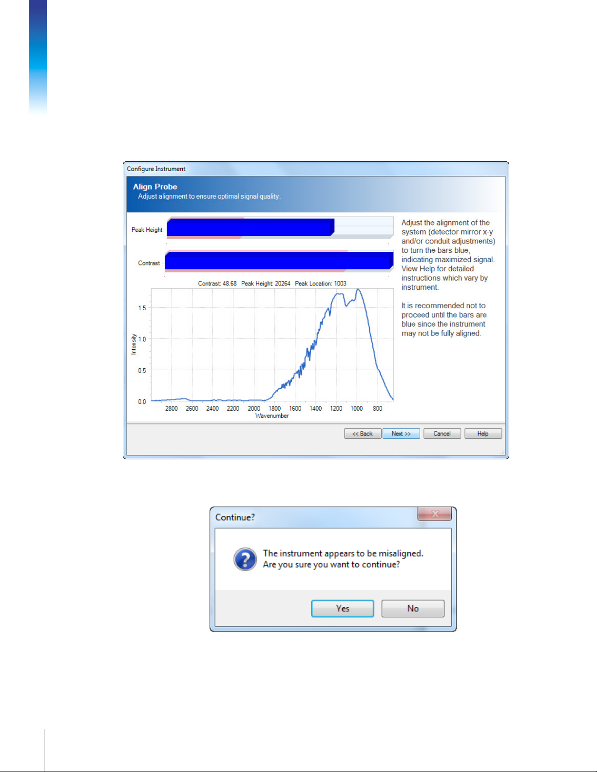
2. In the Align Probe window, observe the Peak Height and Contrast.
6. Installation
• If the bars are blue, the system alignment is optimal. Optimal (maximized) Peak
Height and Contrast indicates plenty of energy is flowing through the system and
sensor to make infrared fingerprints of reaction chemistry components. Click Next.
• If one or both bars are red, the Peak Height is below the 18000– 24000 range and/
or the Contrast is outside of specifications (10–60). Both values should be
maximized within the allowable range, which varies by sampling technology.
MK-PB-0114-AC Rev A 48
METTLER TOLEDO
Figure 6-18 Configure Instrument—Align Probe
If you click Next to proceed when red bars exist, the following message appears:
Figure 6-19 Misalignment message
The instrument is prealigned at the factory. However sampling technology
alignment may be needed to achieve optimal Peak Height and Contrast.
Page 49

For Fiber-to-Sentinel and Mirror Conduit sampling technologies, rotate the
Sentinel/Probe and adjust the last knuckle of the Mirror Conduit (K4 or K6) for
optimal Peak Height (20,000) and Contrast (Minimum of 10). The final
adjustment for Peak Height to reach approximately 20,000 counts may require
adjustment of the preamp gain.
For FiberConduit sampling technologies, adjust the gain if necessary to reach
approximately 20,000 counts using the supplied flat-head screwdriver.
Refer to “Advanced Adjustment Features” on page 54 for gain adjustment details.
3. When the bars are both blue, click Next to continue. If one or both alignment bars
remain ‘red,’ contact METTLER TOLEDO.
4. In the Collect a Clean Reference Background window, click Collect Background to
collect a reference background of the single beam for a clean probe tip sensor without
chemistry (only exposed to air).
Figure 6-20 Configure Instrument—Collect a background single beam
5. Click Finish.
At this point, the first phase of system installation is complete. A METTLER TOLEDO service
engineer fills in the required information in the ServicePac document and proceeds to the next
phase of installation—“System Readiness” testing as described in Chapter 7.
METTLER TOLEDO
49ReactIR™ 45m Hardware Manual
Page 50

6. Installation
MK-PB-0114-AC Rev A 50
METTLER TOLEDO
Page 51
System Readiness
This chapter describes the procedures for system readiness in the following sections:
“Preparing for ReactIR 45m Functional Tests” on page 51
“Conducting Functional Tests Using iC IR” on page 51 .
Caution—If the equipment is used in a manner not specified by the
manufacturer, the protection provided by the equipment may be impaired.
Preparing for ReactIR 45m Functional Tests
The second phase of system installation consists of performance tests of the ReactIR 45m
with its sampling technology. A METTLER TOLEDO service engineer performs functional tests
as the second phase of system installation. This phase follows system installation, so the
system is assumed to be powered on and communicating with the control software.
1. Ensure that Instrument Configuration is completed as described under section “9.
Configure ReactIR 45m Instrument in Control Software” on page 44.
2. Verify the ReactIR 45m LEDs are in the fully operational state: Power light is illuminated,
Scan light is flashing, the MCT light is illuminated, and Temp OK light is illuminated.
(Refer to page 77 for illustration and details.)
3. Ensure the ReactIR 45m system has been powered ON for three (3) hours before taking
critical measurements.
7
IMPORTANT /
CRITICAL!
Ensure that the system and probe are not exposed to any heavy
vibration and/or airflow that could result in extreme ambient
Notes:
As needed, review the terminology in Appendix B starting on page 103 to become familiar
with functional tests.
temperature ramps.
Please follow the test procedures completely to ensure the correct
and comprehensive results.
FROM A COLD START: You must allow a minimum of three
(3) hours warm-up time before you can proceed to make
any alignment adjustments to the system. DO NOT
PROCEED until the unit has been allowed to warm up.
Conducting Functional Tests Using iC IR
Use the procedures below to conduct functional tests of the ReactIR 45m instrument using iC
IR software. Perform functional tests in the following sequence:
51ReactIR™ 45m Hardware Manual
METTLER TOLEDO
Page 52

“1. Check Alignment (Contrast and Align)” on page 52
“2. Clean the Sensor” on page 59
“3. Check System Performance” on page 60
“4. Check System Stability” on page 66
“6. Perform IPA Validation/Calibration (if applicable)” on page 68
1. Check Alignment (Contrast and Align)
By design the alignment process for the ReactIR
45m is quick and easy to enable the rapid
implementation of the system. As a result, you
get to monitoring the data and information
about your chemistry without spending
significant time preparing the reaction analysis
instrument.
The purpose of alignment is to assure the
7. System Readiness
energy of the system (source) properly travels
from the origin to the sample and then to the
detector. Maximum energy reaching the
detector through this optical pathway will yield
an infrared fingerprint characteristic of the
chemistry in contact with the sampling interface
(sensor). Over time these fingerprints
accurately represent the chemistry dynamics
that assist you in understanding the reaction
mechanism and pathway.
1. Select the Test Instrument task pane from
the iC IR Toolbox.
2. Select ReactIR 45m Instrument and
Detector.
3. Select applicable Probe Settings.
4. Select Contrast and Align from the Test
mode section (Figure 7-1).
MK-PB-0114-AC Rev A 52
METTLER TOLEDO
Figure 7-1 Contrast and Align test from iC IR Test
Instrument task pane
Page 53

5. Click Start. The Test Instrument tab appears showing contrast, peak height, and peak
location.
Figure 7-2 Contrast, peak height, and peak location in iC IR Test Instrument task pane
6. The FSE will record Peak Height, Contrast, and Peak Location test values in the
appropriate ServicePac document at initial installation. These values become your
system/probe configuration performance benchmark. Refer to them when testing future
assurance of performance..
Do not proceed with functional tests until optimal alignment exists. Align
Note:
sampling technology, if applicable, and/or follow advanced adjustment
features described in an upcoming section, if necessary.
Aligning Sampling Technology
Note: Ensure the probe window is clean prior to making any adjustments.
If the Contrast and Align test does not result in optimal Peak Height and Contrast, adjust the
sampling technology. This adjustment applies only to the DS Fiber-to-Sentinel technology and
the K4 or K6 Mirror Conduit technology.
Optimal Peak Height is 18,000–24,000 counts
Optimal Contrast is 10–250.
DS Fiber-to-Sentinel
1. Open the Test Instrument task pane in the iC IR toolbox.
2. Select the Contrast and Align Test Mode and click Start.
3. Loosen the clamp and rotate the Sentinel clockwise while observing the Peak Height
and Contrast values.
4. When the values reach the optimal range, tighten the Sentinel clamp.
5. Record the values in the appropriate ServicePac document—IPac StarterPac or IPac
QualityPac.
METTLER TOLEDO
53ReactIR™ 45m Hardware Manual
Page 54

If the alignment values are still outside the optimal range, follow the instructions under
"Advanced Adjustment Features".
Mirror Conduit (K4/Sentinel or K6/16 mm Probe)
1. Open the Test Instrument task pane in the iC IR toolbox.
2. Select the Contrast and Align Test Mode and click Start.
3. If the Peak Height Value is out of range (18000–24000), go to the Advanced Tools
section at the bottom of the window.
• Loosen the clamp and rotate the sensor on the last knuckle of the conduit to optimize
the Peak Height and Contrast values. Then, tighten the clamp.
• Adjust the three (3) thumbscrews on the last knuckle of the conduit to optimize Peak
Height and Contrast values.
• Select Detector XY in the Motor Selection.
• Select Auto-align from the Alignment Option.
• Click the Start button.
4. If the Peak Height value is low after completion of Auto-align, adjust the Gain
potentiometer on the detector Preamp to bring the Peak Height value as close as
possible to 20,000 counts (see "Adjusting Gain Potentiometer" in the next section).
7. System Readiness
5. Run a Performance Test to verify the SNR value meets specification to ensure optimal
alignment.
Advanced Adjustment Features
Ensure the probe window is clean prior to making any adjustments.
Note:
When the Peak Height and Contrast values are within the optimal range, no advanced
alignment should be necessary.
When the values are outside the optimal range (18,000–24,000) and sampling technology
alignment has been performed, where applicable, follow one of the advanced procedures to
adjust the fixed mirror and/or gain. For example, this adjustment is often needed if you switch
sampling technologies.
When switching from a DS Micro Flow Cell or Mirror Conduits to a AgX FiberConduit
When switching from an AgX FiberConduit Probe or AgX Fiber-to-Sentinel to a DS Micro
Perform advanced alignment procedures with a fully functional
instrument.
Probe or AgX Fiber-to- Sentinel, the gain pot on the preamp will need to be turned up
(clockwise)
Flow Cell or Mirror Conduit, the gain pot on the preamp will need to be turned down
(counterclockwise)
Adjusting Gain Potentiometer
If the Peak Height or Contrast values remain outside the optimal range after completion of
sampling technology alignment, adjust the Gain potentiometer to bring the Peak Height value
as close as possible to 20,000 counts. Although each control software has a gain setting
field in the instrument configuration, the recommended process is to manually adjust the
gain, if needed, during initial system readiness testing. Gain adjustment is also necessary
when switching sampling technologies to achieve optimal Peak Height and Contrast.
MK-PB-0114-AC Rev A 54
METTLER TOLEDO
Page 55
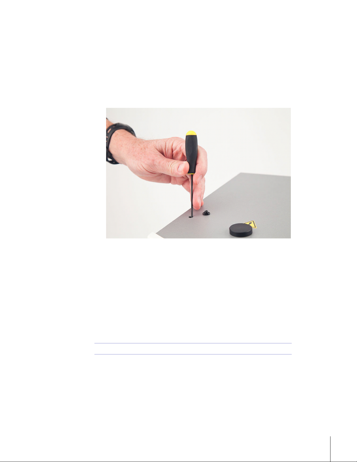
If using a MultiplexIR, the gain adjustment should be made in the Configure Instrument wizard
instead of the physical adjustment as this preamp gain adjustment will impact both probes
attached to the MultiplexIR. For example, one probe may have a low Peak Height and the
other may have a high Peak Height, so you would want to adjust them individually via
software configuration.
The system must be powered on and LEDs fully functional for this adjustment.
1. Remove the cap from the gain adjustment opening on top of the ReactIR 45m base
unit.
Figure 7-3 Adjusting gain (manually)
2. Insert a flathead screwdriver and gradually adjust the potentiometer while observing the
Peak Height and Contrast values (Figure 7-2).
• Clockwise rotation increases Peak Height.
• Counterclockwise rotation decreases Peak Height.
3. Do one of the following steps, depending on results:
• If the optimal values are not yet attained, contact METTLER TOLEDO.
• If optimal values are attained, run a Performance Test (“Signal-to-Noise Ratio
(SNR)” on page 61) to verify the SNR value meets specification. This ensures
optimal alignment.
Adjusting Fixed Mirror Alignment
Note: IMPORTANT! This adjustment requires prior training from an FSE or TAC.
Fixed mirror alignment may be necessary after shipment or relocation of the ReactIR 45m. To
assure the mirror position is in an optimal position, follow the short procedure that checks
the position and if necessary aligns the fixed mirror.
1. Launch the fixed mirror test program in iC IR software Toolbox, Test Instrument task
pane. Click on the Advanced tab located in the lower-left corner of the contrast screen to
open the fixed mirror adjustment panel.
METTLER TOLEDO
55ReactIR™ 45m Hardware Manual
Page 56

2. Using the toggle buttons (N, S, W and E,) verify/optimize proper alignment of the fixed
mirror for maximum peak height and contrast levels.
3. Verify the shape of the single beam is consistent with the sampling technology using
the images below.
7. System Readiness
Figure 7-4 SiComp AgX FiberConduit probe (6.3mm)
MK-PB-0114-AC Rev A 56
METTLER TOLEDO
Page 57

Figure 7-5 DiComp AgX FiberConduit probe (9.5mm)
Figure 7-6 DiComp DS Micro Flow Cell
Figure 7-7 SiComp DS Micro Flow Cell
METTLER TOLEDO
57ReactIR™ 45m Hardware Manual
Page 58

7. System Readiness
Figure 7-8 DiComp Fiber-to-Sentinel
MK-PB-0114-AC Rev A 58
METTLER TOLEDO
Figure 7-9 SiComp Fiber-to-Sentinel
4. The FSE will record the Peak Height, Contrast, and Peak Location values in the
ServicePac document. If you perform a routine alignment after initial installation, record
the values in a log book.
Page 59

2. Clean the Sensor
The probe tip and DS Micro Flow Cell contain a diamond or silicon composite sensor that
samples the reaction mixture to produce infrared fingerprints of the molecular composition.
Cleaning the sensor eliminates any chance of observing infrared fingerprints from a previous
reaction or sample measurement, thus assuring an accurate representation of the reaction of
interest. A simple process of cleaning the sensor and checking cleanliness using an iC IR
software is a good practice to go through before running performance tests or any other
experiment.
Note:
Clean the probe or DS Micro Flow Cell using the most appropriate solvent(s) to dissolve any
residue, solvent, or chemical component. A final cleaning with reagent grade acetone is
recommended. A virgin cotton swab on a wooden stick makes an ideal cleaning tool for the
sensor surface in the case of probe cleaning.
Note:
1. Clean the probe, as described above.
2. Click Configure Instrument on the iC IR Start Page
3. Proceed through the wizard by clicking Next until you reach the 'Collect Clean
4. Click Collect Background to collect a reference background to prepare the wizard for a
5. Click Finish. This action skips the ‘water vapor’ collection and exits the wizard.
6. Click New Experiment on the iC IR Start Page.
7. Click Next and click Next again to reach the ‘Reference Spectra Needed?’ wizard
8. Select ‘Collect reference spectra (recommended)’ and click Next.
9. Click Next and click Next again to reach the ‘Clean Probe’ wizard window.
Ensure the probe is not in contact with any chemicals (exposed only to
air) before proceeding.
Q-tips and similar type swabs have lubricants and are not a great choice
for a cleaning tool!
Reference Background.'
sensor cleanliness check and click Next.
window.
METTLER TOLEDO
59ReactIR™ 45m Hardware Manual
Page 60

10. Observe the two colored bars that indicate if the sensor is clean or dirty.
7. System Readiness
Figure 7-10 Collect Clean Reference Background in iC IR
• If the bars are green, the sensor is ready for monitoring chemistry.
• If the bars are red and in the red area of the purge and clean zone, the probe surface
or DS Micro Flow Cell need further cleaning.
Note:
11. If the clean sensor check indicates the probe is not ready, repeat the clean procedure
and take another 'Background' until the bars turn green. At this point the sensor is ready
for monitoring chemistry.
12. Click Finish.
13. The FSE will check off this action in the ServicePac document if performing an initial
installation, or using the form to requalify the performance.
The Intensity versus Wavenumber image will appear as a relatively flat
line when the sensor is clean and the indicator bars are green.
3. Check System Performance
ReactIR 45m system performance is a combination of tests, defined on page 104:
“Signal-to-Noise Ratio (SNR)” on page 61
“Acetone Peak Height and Average ANR” on page 62
MK-PB-0114-AC Rev A 60
METTLER TOLEDO
Page 61

Signal-to-Noise Ratio (SNR)
A good measure of ReactIR 45m performance is the Signal-to-Noise Ratio (SNR). This value
represents a specific method of measurement at METTLER TOLEDO that historically defines
performance according to the original design specification. The value recorded in the
ServicePac document will define the reference point for verification of ReactIR 45m
performance when executing the test at anytime in the future.
1. Ensure the sensor is clean and dry, and void of
any potential contact with solvent or reaction
mixture.
2. Select the Test Instrument task pane from the
Toolbox
3. Select ReactIR 45m Instrument and Liquid N2
MCT Detector.
4. Select applicable Probe Settings.
5. Select Performance from the Test mode section
(Figure 7-11).
6. Click Start.
Figure 7-11 Performance test (iC IR Test Instrument task
pane)
7. Enter 10 as the number of runs, and click OK.
Figure 7-12 SNR Number of runs
61ReactIR™ 45m Hardware Manual
METTLER TOLEDO
Page 62

Note:
The Performance test window (Figure 7-13) opens to display trend chart and values as
the system collects 10 background / sample pairs. The parameters used for collection
are one (1) minute scan time and 4 cm
Do not adjust the region as this automatically defaults to the appropriate
settings based upon the Sampling Technology.
7. System Readiness
-1
resolution.
Figure 7-13 Performance SNR test in iC IR
8. Wait for test to complete.
The test will complete and create a “Results” tab. Proceed through the next steps for
Acetone and then go to the Results tab and record results.
9. Proceed to Acetone Peak Height test.
Acetone Peak Height and Average ANR
Another good measure of ReactIR 45m performance is the Acetone Peak Height. This value
indicates sensor integrity in a probe or Micro Flow Cell by measuring the peak height with
acetone on the sensor.
Note:
The Select Acetone Test Runs window will appear immediately following
completion of the SNR test described in the previous section.
MK-PB-0114-AC Rev A 62
METTLER TOLEDO
Page 63

1. Enter 4 in the number field for the number of tests.
Figure 7-14 Acetone Peak Height—Number of runs
This step instructs the system to collect four acetone spectra.
2. Ensure the sensor is clean and dry. Take note of the precaution in the Acetone Peak Test
window.
3. Click OK. Wait until the background is collected and the following message appears.
4. Dip the probe into a vessel, vial, or beaker that contains neat acetone.
Make sure the liquid completely covers the sensor surface.
5. Select OK.
The system will collect the requested number of acetone spectra.
The Acetone Peak Height is calculated automatically by the following equation:
Absorbance
cm-1 – Absorbance
1092
cm-1 = Acetone Peak Height
1018
METTLER TOLEDO
63ReactIR™ 45m Hardware Manual
Page 64
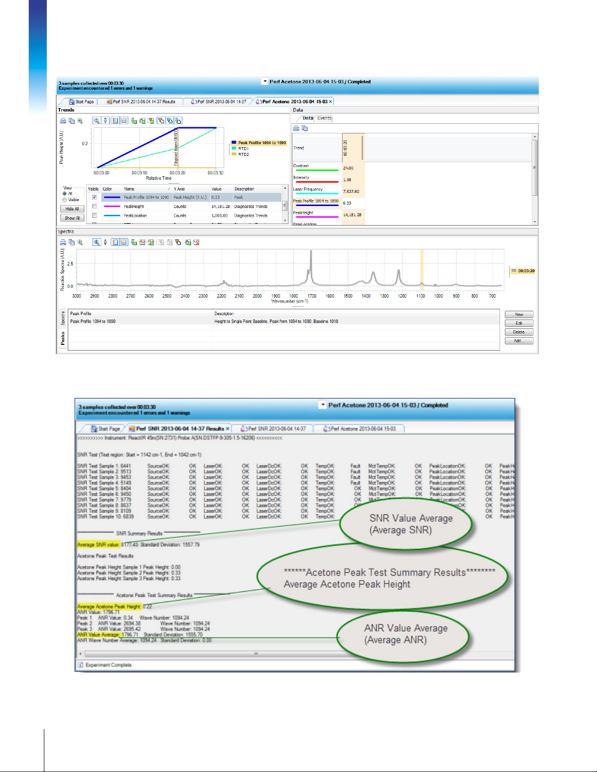
7. System Readiness
6. After the test completes, a Results tab provides summarized values (Figure 7-16).
Figure 7-15 Performance—Acetone Peak Height
MK-PB-0114-AC Rev A 64
METTLER TOLEDO
Figure 7-16 Performance SNR results in iC IR
Page 65

• The FSE will record the Average Acetone Peak Height and Average ANR in the ‘Perf
SNR’ tab in the ‘Performance Test Values’ section in the appropriate ServicePac
document.
• Record the Average SNR Value in the appropriate ServicePac document.
7. Check the Performance Test Results—Signal-to-Noise Ratio (SNR), Acetone-to-Noise
Ratio (ANR), and Acetone Peak Height (APH) values—against the criteria in the
“Reaction Analysis Performance Specifications” quick reference guide (MK-RF-0016AC). The guide is in the ReactIR 45m Hardware Documentation Portfolio shipped with
your system and also on the AutoChem Customer Community website.
8. Contact METTLER TOLEDO Service if your system performance values fall below the
factory specifications.
A Note About Acetone-to-Noise Ratio (ANR)
Acetone-to-Noise Ratio (ANR) is the product of SNR and Acetone Peak
Height. ANR is an automatic calculation in the software using the
following formula:
Note:
(Acetone Peak Height) x (Signal to Noise) = ANR
For reference purposes, an ANR of approximately 1200 indicates a
detection limit of approximately 0.1 wt% for a moderate infrared
absorbance feature specific to the reactant or product.
METTLER TOLEDO
65ReactIR™ 45m Hardware Manual
Page 66
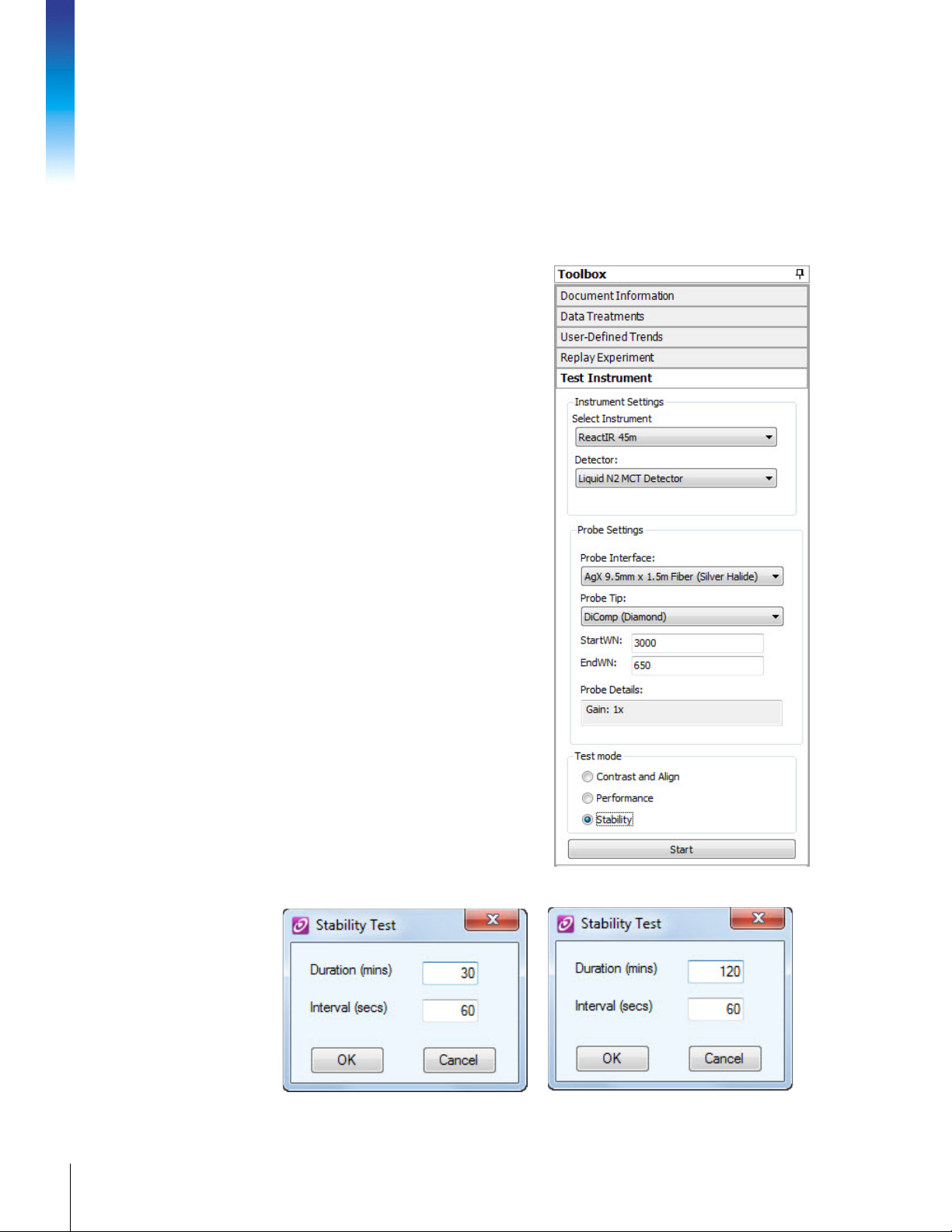
4. Check System Stability
ReactIR stability is a measure of performance consistency over a period of time. Regular
infrared measurements as a function of time, in the same manner as monitoring a reaction,
reveal stability information through % Transmittance trends at specific wavenumber
locations. This test uses the variation in the % transmittance trends to measure ReactIR 45m
stability.
Prior to checking stability, ensure the ReactIR
45m has been powered on for at least three (3)
hours. The Power and Scan LEDs should be in
a fully functional state (see “ReactIR 45m LED
Indicators” on page 77). If the LEDs show
anything other than fully functional, do not
proceed. Contact METTLER TOLEDO Customer
Care using the information page 9.
1. Select the Test Instrument task pane from
the iC IR Toolbox.
7. System Readiness
2. Select the ReactIR 45m instrument and the
appropriate Instrument and Detector.
3. Select applicable Probe Settings.
4. Select Stability from the Test mode section
(Figure 7-17).
5. Click Start.
MK-PB-0114-AC Rev A 66
METTLER TOLEDO
Figure 7-17 Stability test selected from iC IR Test
Instrument task pane
A Stability Test window prompts you to enter test Duration and Interval.
Figure 7-18 Stability test duration and interval entries
Page 67

6. Enter ONE of the following Duration times, based on the type of ServicePac installation:
30 minutes (IPac StarterPac) or
120 minutes (IPac QualityPac)
7. Enter 60 in the Interval field and click OK.
These parameters correspond to a 30-minute or two-hour test that collects a spectrum
every 60 seconds. T
successive sample spectra over the
he stability test starts by collecting a background and then
30-minute or two-hour
period. The software
automatically measures and plots the % Transmittance value at the wavenumbers that
correspond to the sampling technology
.
8. Wait for the test to complete.Then, values appear in the ‘Stability Test Results’ tab under
******Summary Results****** (Figure 7-19).
Pass criteria is: plus/minus 4 %T.
Figure 7-19 Stability test result summary in iC IR
9. Contact METTLER TOLEDO Service if your system stability value (%T) is greater than the
factory specification.
METTLER TOLEDO
67ReactIR™ 45m Hardware Manual
Page 68

6. Perform IPA Validation/Calibration (if applicable)
If the IPac QualityPac was purchased, perform an IPA (Instrument Performance Assurance)
validation and, if necessary, a calibration. The IPA process compares the instrument to the
NIST standards for polystyrene. Refer to the quick reference guide: “Instrument Performance
Assurance (IPA) for ReactIR Systems in your hardware portfolio (MK-PB-0111-AC).
1. Temporarily remove the sampling technology and attach the DS IPA module to the
Single Optical Interface or MultiplexIR.
2. Select the Instrument Performance task pane from the iC IR Toolbox.
7. System Readiness
MK-PB-0114-AC Rev A 68
METTLER TOLEDO
Figure 7-20 IPA task pane
3. Click Run Validation.
Page 69
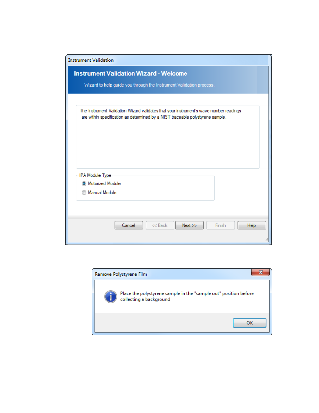
4. Choose Manual Module In the IPA Module Type section of the Instrument Validation
window and click Finish.
Figure 7-21 IPA Validation wizard
The following prompt appears:
Figure 7-22 IPA message—Remove polystyrene film
Verify the polystyrene film is in the “Sample Out” position, and click OK. Then, click
Finish.
METTLER TOLEDO
69ReactIR™ 45m Hardware Manual
Page 70

5. Click Collect Background.
7. System Readiness
Figure 7-23 IPA—Collect background
When background collection completes, click Next.
Move the polystyrene film to the ‘Sample In” position when the following prompt appears.
Then, click OK.
Figure 7-24 IPA message—Insert polystyrene film
MK-PB-0114-AC Rev A 70
METTLER TOLEDO
Page 71

6. When the Collect Polystyrene Samples window appears, click Collect Sample to begin
the validation..
Figure 7-25 IPA—Ready to collect polystyrene samples
7. Observe the collection of six samples.
Figure 7-26 IPA—Collecting validation samples
71ReactIR™ 45m Hardware Manual
METTLER TOLEDO
Page 72

After six samples have been collected and compared to the NIST standard for
polystyrene, the Finish button becomes enabled.
8. Click Finish to observe the results in table format.
• If the validation test passed, the table will appear similar to Figure 7-27.
Click Finish again. For steps to view test results, go to page 74.
• If the validation test failed, the Validation Results window will appear similar to the
7. System Readiness
following:
Figure 7-27 IPA—Validation results table (passed)
MK-PB-0114-AC Rev A 72
METTLER TOLEDO
Figure 7-28 Validation results (failed)
Click Finish and run a calibration (refer to “Performing a Calibration” on page 73).
Page 73

Performing a Calibration
A calibration follows the same process as the validation, except the instrument can be
calibrated after the test process. When performing calibration test, the last step is to commit
the new calibration to the instrument and reconfigure the instrument.
1. Go to the Instrument Performance task pane in the iC IR toolbox and scroll to the bottom
of the task pane.
2. Click Run Calibration.
3. The calibration process follows the same steps as the validation (refer to step 4 through
step 8, starting on page 69). The Calibration wizard guides you through the procedure.
4. When the calibration test completes, the Calibration Results window appears. Notice
the results window includes a Commit Calibration Result button.
Figure 7-29 Calibration results (passed)
5. If any of the six measurements failed to compare properly with the NIST standard for
polystyrene, click Commit Calibration Result and respond to the warning message
(Figure 7-30).
73ReactIR™ 45m Hardware Manual
METTLER TOLEDO
Page 74

6. If you answer Yes to commit the new calibration, the following message prompts you to
run the Configure Instrument wizard (see “9. Configure ReactIR 45m Instrument in
Control Software” on page 44):
7. System Readiness
Viewing/Printing IPA Test Results
To review or print completed validation or calibration test results:
1. Click View History from the Instrument Performance task pane (Figure 7-20 on
page 68).
Figure 7-30 Calibration commit prompt
Figure 7-31 Calibration prompt fo configure instrument
MK-PB-0114-AC Rev A 74
METTLER TOLEDO
Note:
There are two separate buttons to view the validation history and
calibration history, so scroll down to locate the View History button
for calibration.
Page 75

A list of past validation (or calibration) tests appears. Figure 7-32 shows a single
validation test in the history list
Figure 7-32 IPA validation history
2. Select a test to highlight it, and click View Test Details.
3. From the Details window, you can choose to Print Test Results.
Refer to the iC IR software online Help or the “IPA Software User Guide” for more information.
METTLER TOLEDO
75ReactIR™ 45m Hardware Manual
Page 76

7. System Readiness
MK-PB-0114-AC Rev A 76
METTLER TOLEDO
Page 77

Routine Operation
ReactIR 45m system readiness is checked during the final phase of initial installation
according to the applicable ReactIR 45m IPac StarterPac or IPac QualityPac service package.
Chapter 6 outlines system installation and Chapter 7, system readiness tests. This chapter
describes the routine operation of a ReactIR 45m system including steps to begin an
experiment. Also included are suggestions on the most efficient way to use the system to
monitor chemistry in a laboratory or kilo lab.
WARNING—Use of this product in a manner not specified by the
manufacturer may result in serious injury and/or damage to the
equipment and will void the warranty. Protection provided by the
equipment may be impaired.
ReactIR 45m LED Indicators
Figure 8-1 shows the four LEDs on the front panel of the base unit that indicate the status of
instrument power, scanning/communication, and readiness for use. Frequent checks of these
indicators enable recognition of instrument conditions that may require attention to assure
measurement accuracy. A fully functional system will yield solid blue Power, Temp OK, and
MCT OK indicators and a flashing blue Scan indicator.
8
Figure 8-1 ReactIR 45m LEDs (fully functional state)
LED statuses highlighted in Table 8-1 indicate full system readiness.
Table 8-1 ReactIR 45m LED Indicators
LED Status Description
1
2
OFF ReactIR 45m is without power.
Blue—Solid System is powered.
Power
OFF System not scanning.
Blue—Flashing System is scanning and ready to send data to software application.
Scan
Flashing occurs after connection of the USB cable between the instrument
base unit and the iC IR control computer, and when both devices are ON.
NOTE: The software must be loaded on the control computer so the
drivers are loaded and recognized by the instrument and computer.
77ReactIR™ 45m Hardware Manual
METTLER TOLEDO
Page 78

Table 8-1 ReactIR 45m LED Indicators (continued)
LED Status Description
Blue—Solid MCT detector temperature has cooled down to its operating temperature
3
MCT OK
OFF Fault condition (see >step 4 below).
Blue—Solid Modulator temperature has reached its set point. Time required may be
4
OFF Fault condition.
Temp OK
4. If the MCT OK LED is not lit, verify that the dewar is filled with liquid nitrogen. The LED
lights after you fill the dewar. For instructions, go to the “E. Fill the Detector Dewar” on
page 79.
Refer to Chapter 10, “Troubleshooting and FAQs” if the LEDs do not indicate system
readiness.
Preparing for System Use
of –196 °C [–321 °F] after filling the dewar with liquid nitrogen. Time
required is at least five minutes.
up to four (4) hours.
8. Routine Operation
ReactIR 45m operates using iC IR software in a laboratory environment. The procedures
below assume the system is installed and the instrument communication with the control
software has been established during system installation and readiness testing.
1. Ensure the ReactIR 45m IPac StarterPac or IPac QualityPac documents are complete.
2. Ensure appropriate mounting options are available for inserting the probe in the reactor.
A. Connect Sampling Technology to ReactIR 45m Base Unit
During system installation, the purchased sampling technology is connected to the
base unit and the system is aligned and tested with the installed sampling technology.
This step only applies if you are changing sampling technologies.
1. Attach the sampling technology to the SIM flange on the front of the ReactIR 45m
base unit enclosure. Refer to section “G. Connect Sampling Technology” on
page 39 for detailed steps.
2. If applicable, connect air to sampling technology. This step only applies to Fiber-to-
Sentinel or MirrorConduit configuration (see “6. Establish Sampling Technology
Conduit Purge (if applicable)” on page 41).
B. Start Up System
1. Apply power and purge to the ReactIR 45m system.
2. Set purge pressure to nominal
[10 SCFH].
0.69 bar [10 psi]
and flow rate to
4.7 LPM
MK-PB-0114-AC Rev A 78
METTLER TOLEDO
C. Ensure the ReactIR 45m is ON for Three Hours
Before taking critical measurements, the ReactIR 45m system must be powered on for
at least three (3) hours so the instrument electronics are warmed up and internal
temperature is stable. Purging the base unit, and if necessary the sampling technology,
Page 79

during this time period will assure minimal water vapor and carbon dioxide changes
during experiments.
Note:
For startup immediately following installation, the above steps will not be
necessary unless you are relocating the instrument.
D. Launch the iC IR Software
1. Turn on the control computer.
2. Start the iC IR software from the Start menu or by clicking the desktop icon.
3. Observe the LEDs on the front of the base unit to confirm fully operational system
(page 77). Power and Temp OK LEDs should be illuminated and the Scan LED
should be flashing.
Instrument configuration should already be complete as part of the installation
procedure (“9. Configure ReactIR 45m Instrument in Control Software” on page 44).
E. Fill the Detector Dewar
Ensure the dewar is filled. The MCT OK LED should be illuminated once the dewar is full
and the detector reaches operating temperature. The detector operates to maximum
performance for up to 24 hours without refilling. Instructions begin on page 37.
Simple Steps to a Successful Experiment
Getting the most out of your ReactIR 45m requires simple steps that lead to the monitoring of
your chemistry. The data will then be of the highest quality for easy conversion to chemical
information that you can use for better understanding of the reaction dynamics. All of the
actions center around gaining maximum performance of the ReactIR 45m through the iC IR
software tools. Once complete, you can be certain that the infrared fingerprints accurately
reflect chemical changes pertinent to your chemistry.
Below are the steps:
“1. See An Overview of the Process” on page 79
“2. Interface Sampling Technology with Your Chemistry” on page 80
“3. Align the Probe” on page 82
“4. Clean the Sensor” on page 83
“5. Collect a Background” on page 86
“6. Set the Data Collection Parameters” on page 90
Refer to “Best Practices” on page 90 for additional guidelines.
1. See An Overview of the Process
The following useful references are available to help you learn more on this subject:
“Experiment Setup in iC IR” (MK-PB-0013-AC)—Included in your Software Documentation
Portfolio available through iC IR Help > Show Documentation Portfolio. This is a Quick
METTLER TOLEDO
79ReactIR™ 45m Hardware Manual
Page 80

Reference guide that provides instructions on the basics of ReactIR 45m hardware and iC IR
software for starting an experiment.
2. Interface Sampling Technology with Your Chemistry
Interfacing the sampling technology with your chemistry will lead to data and information
about the reaction. Start by placing the reaction vessel within reach of the probe end of the
8. Routine Operation
sampling technology or flow distance of the Micro Flow Cell.
DS FiberConduit Probe
“iC IR Guided Tour”—A link to the tour is in the More Information
section of the iC IR Start Page. The tour is a video that provides a
concise overview of the software with special attention to
efficiently collecting data and converting it to information. To
review a specific part of the tour, click the small ‘Jump to’ link
above the tour window and select from the list.
Figure 8-2 Guided Tour segment selection link
A short procedure will establish the correct orientation of the probe tip in the reaction vessel
before adding solvent and reagents. Use an adapter to assure a secure fit of the probe in one
of the vessel ports. Check with your Technology Applications Consultant (TAC) to make sure
you have the appropriate adapter for your specific vessel.
1. With the right adapter in place, insert the probe through the adapter and secure with the
plastic compression fitting. Do this step prior to or after inserting the adapter in the
reaction vessel.
Figure 8-3 DS FiberConduit with adapter in common reaction vessels
2. Adjust the insertion depth of the probe into the vessel to assure complete coverage of
the tip throughout the experiment. The vessel contents should be empty at this point to
collect an 'air background.'
MK-PB-0114-AC Rev A 80
METTLER TOLEDO
Page 81
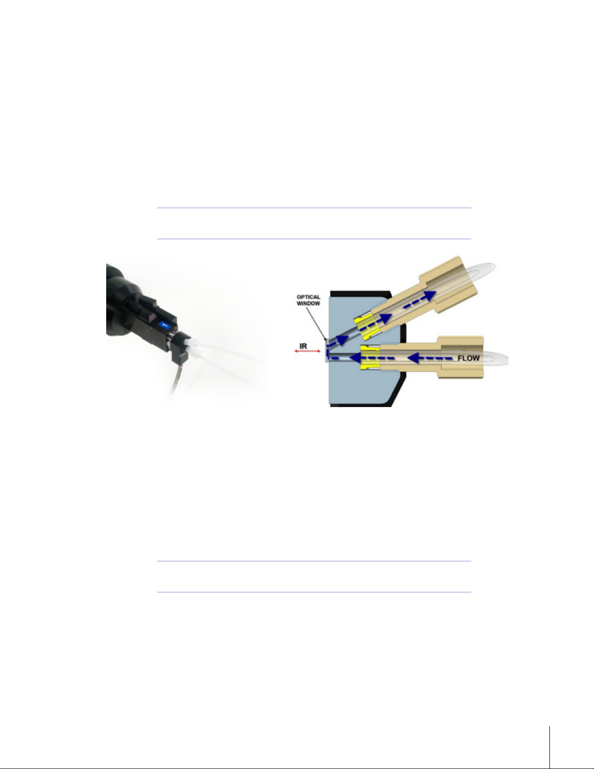
DS Micro Flow Cell
Monitoring reaction chemistry requires injection of solvent and reagents or flow of the liquid
solution into the DS Micro Flow Cell. Establish connections to the cell using the specified
Omnifit-style fittings (not provided). Mate the opposite end to the reaction chemistry to allow
continuous flow. Alternately, create a shorter length of tubing to afford easy injection of solvent
and reagents.
For additional instructions on the subject please read the Quick Reference Guide: “Connecting
a DS Micro Flow Cell” that ships with the DS Micro Flow Cell product and is included in the
ReactIR and iC IR documentation portfolio.
Note:
Be sure to collect an 'air background' before introducing liquid reaction
chemistry into the DS Micro Flow Cell.
Figure 8-4 DS Micro Flow Cell (heated) and Omnifit-style fittings
DS Fiber-to-Sentinel
Reaction vessels (large volume flow cells, high pressure autoclaves) with a proprietary
connection design are necessary to insert and secure a Sentinel probe in contact with liquid
chemistry. Each Sentinel comes with the hardware and liquid seal to safely secure the
connection. Check with your Technology Applications Consultant (TAC) to make sure you
have the appropriate vessel and fitting to safely secure the connection. Once the sentinel is
secured in the reaction vessel, use the supplied clamp to connect the DS Fiber-to-Sentinel to
the Sentinel probe.
Note:
Be sure to collect an 'air background' before introducing liquid reaction
chemistry into the DS Fiber-to-Sentinel.
81ReactIR™ 45m Hardware Manual
METTLER TOLEDO
Page 82

DS Fiber-to-Gas Cell
Secure the gas cell to a suitable mounting location. Connect the Fiber-to-Gas Cell sampling
technology to the gas cell mating flange with the supplied clamp.Monitoring reaction gases
requires connection to the Gas Cell through the 6.35 millimeter [1/4-inch] input and output
ports. You supply the gas sample and hardware to adjust flow and pressure.
Note:
Be sure to collect an 'air background' before introducing gas samples
into the Gas Cell.
K4 Mirror Conduit
Reaction vessels (large volume flow cells, high pressure autoclaves) with a proprietary
connection design are necessary to insert and secure a Sentinel probe in contact with liquid
chemistry. Each Sentinel comes with the hardware and liquid seal to safely secure the
connection. Check with your Technology Applications Consultant (TAC) to make sure you
have the appropriate vessel and fitting to safely secure the connection. Once the Sentinel is
secured in the reaction vessel, connect the K4 conduit to the Sentinel probe with the supplied
8. Routine Operation
clamp.
K6 Mirror Conduit
Reaction monitoring in laboratory scale vessels will require direct insertion of the 16millimeter probe into the liquid-based chemistry. The K6 conduit connected to the 16millimeter probe will direct the infrared energy to the probe for measurements of the chemical
changes during the reaction.
1. Orient the K6 conduit and 16-millimeter probe for insertion of the probe into a reaction
vessel.
2. Install the appropriate adapter onto the 16-millimeter probe.
3. Insert the 16-millimeter probe into the reaction vessel.
4. Secure the probe with the adapter fitting making sure the liquid level will submerge the
probe tip.
5. Be sure to collect an air background before filling the vessel with liquid.
3. Align the Probe
MK-PB-0114-AC Rev A 82
METTLER TOLEDO
We recommend checking alignment before each experiment using a simple software wizard.
The purpose is to assure the energy of the system (source) properly travels from the origin to
the sample and then to the detector. By aligning maximum energy through this optical
pathway, the ReactIR 45m will yield an infrared fingerprint characteristic of the chemistry in
contact with the sampling technology (sensor).
A successful Operational Qualification sets the stage for routine use of the Align Probe wizard
prior to an experiment. Use the following steps to access and implement the wizard.
1. Click Configure Instrument on the iC IR Start Page.
2. If necessary, configure the instrument per the instructions in “9. Configure ReactIR 45m
Instrument in Control Software” on page 44.
Page 83

3. Proceed through the wizard by clicking Next until you reach the 'Align Probe' window.
Figure 8-5 Align Probe wizard—From red to blue bars
4. Check the Peak Height and Contrast bars at the top of the Align Probe window.
• If the indicator bars are both Blue, then alignment is OK.
• If the indicator bars are Red, exit and return to the alignment procedures starting
under “1. Check Alignment (Contrast and Align)” on page 52 to adjust the following:
DS Fiber-to-Sentinel—This step is not necessary for DS FiberConduit Probe, Micro
Flow Cell, or Fiber-to-Gas Cell. To align Fiber-to-Sentinel sampling technology, refer
to steps on page 53.
Advanced Adjustment—Refer to adjustment steps on page 54. For K6/K4 Mirror
Conduits, refer to the Alignment chapter of the “ReactIR Sampling Technology
Guide” (MK-PB-0008-AC).
5. If the indicator bars are still Red after sampling technology and/or gain adjustment, exit
the wizard and contact METTLER TOLEDO. Contact information is on page 9.
4. Clean the Sensor
Cleaning the probe or DS Micro Flow Cell is recommended after each experiment. This action
eliminates any chance of observing infrared fingerprints from a previous reaction or sample
measurement, thus assuring an accurate representation of the reaction of interest. Follow the
instructions under “4. Clean the Sensor” on page 83 to properly clean either type of sampling
technology.
Although you will clean the 'wetted' surfaces of the probe or DS Micro Flow Cell, the most
important part is the sensor (DiComp or SiComp in most cases) since it is the true sampling
surface when measuring reaction chemistry. The sensor is at the tip of a probe and inside the
cavity volume of a DS Micro Flow Cell. Both sampling technology types are accessible for
liquid and physical cleaning.
Note:
Ensure the probe is not in contact with any chemicals (exposed only to
air) before proceeding.
83ReactIR™ 45m Hardware Manual
METTLER TOLEDO
Page 84
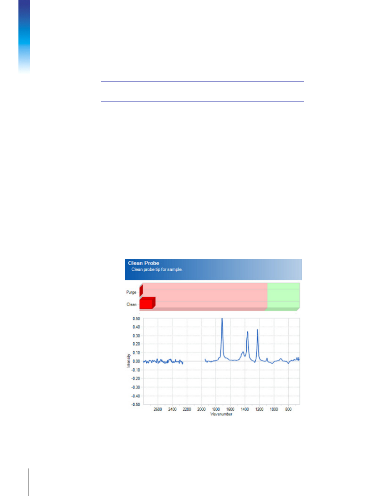
Clean the probe or DS Micro Flow Cell from the previous experiment using the most
appropriate solvent(s) to dissolve the reaction species. A final cleaning with reagent grade
acetone is recommended. A virgin cotton swab on a wooden stick makes an ideal cleaning
tool for the sensor tip in the case of probe cleaning.
Note:
The iC IR 'Clean Probe' wizard dramatically speeds the cleaning process. Once in the wizard,
you can quickly determine whether cleaning is necessary, as well as observe the impact of
the clean method. The following images show possible types of 'dirty' sensors and the
desirable end result.
Peaks pointing in the positive direction (Figure 8-6) indicate one of two situations.
Sensor has materials present on the surface relative to the last background
8. Routine Operation
Residual cleaning solvent is present on the sensor surface. Wait for the solvent to dry,
Q-tips® and similar type swabs have lubricants and are not an ideal
choice for a cleaning tool!
measurement, likely taken immediately after cleaning the sensor. This is a common
occurrence if the probe has not been cleaned following an experiment. Enough residual
reaction mixture is on the sensor to yield an infrared fingerprint. If you do not clean before
the next experiment the residue can cause inaccurate measurement of reaction
component trends.
assuming no residue will result, or wipe with a clean kimwipe. If a residue persists,
choose another solvent for a final rinse.
Dirty Sensor Examples
MK-PB-0114-AC Rev A 84
METTLER TOLEDO
Figure 8-6 'Dirty' sensor—Prior reaction mixture or insufficient drying time of cleaning solvent
Page 85

Figure 8-7 'Dirty' sensor—Poor cleaning method and subsequent collection of new background
Peaks pointing in the negative direction (Figure 8-7) are a result of cleaning a residue off the
sensor relative to the last background measurement. For example, not cleaning the residue
from a previous experiment (described above) and collecting a new air background will
essentially include the residue in the background spectrum. When you finally clean the
sensor, the negative peaks will appear since the residue is no longer present on the sensor
relative to the original background spectrum.
When the sensor is ‘dirty,’ repeat the following steps until you see green indicator bars and a
flat spectrum line:
1. Clean the sensor free of any visible residue.
METTLER TOLEDO
85ReactIR™ 45m Hardware Manual
Page 86

2. Check sensor cleanliness using 'Clean Probe' wizard.
8. Routine Operation
Figure 8-8 'Clean' sensor—Green indicator bars and flat spectral line
• If positive peaks are present, repeat the cleaning process until green indicator bars
appear and a flat spectral line is present, proceed through the wizard.
• If negative peaks are present:
a. Collect a new background by clicking Back in the New Experiment wizard until
you reach the 'Name Experiment File' page.
b. Click Configure Instrument.
c. Click Next to reach the 'Collect Clean Reference' page.
d. Click Collect Background to apply the new background to the 'Clean Sensor'
wizard.
e. Click Next and then Finish to return to New Experiment wizard.
f. Proceed to 'Clean Probe' page.
g. If negative peaks persist then repeat the process or change cleaning solvent
until green indicator bars appear and a flat spectral line is present.
5. Collect a Background
The collection of an air background prior to each experiment is the single-most important step
in getting high quality infrared data out of a fully functional ReactIR 45m. Every sample
measurement following this step will use the background to 'ratio out' all infrared absorbing
materials in the optical path and the source intensity profile. The end result is an infrared
fingerprint of absorbance versus wavenumber of only the reaction mixture components. A flat
baseline will appear at whatever wavenumbers are non-absorbing by the chemistry.
MK-PB-0114-AC Rev A 86
METTLER TOLEDO
Page 87

For example, water vapor will always be present in the ReactIR 45m at a very small and
constant concentration, and the air background will show the characteristic fingerprint.
Subsequent collection of air samples will also contain the water vapor in the raw single beam
(intensity versus wavenumber). However, subsequent ratio of sample to background single
beam eliminates the water vapor to produce a flat zero absorbance in air. Note in Figure 8-9
that all other absorbing features (sensor, AgX, source energy profile) also ratio out of the
sample spectrum. This processing is a routine step in an infrared spectroscopy measurement
that the software performs automatically.
Background Sample
Result from ‘ratioing’
Figure 8-9 Water Vapor in background and sample (plus the result of ‘ratioing’)
Results from Infrequent Background Collection
Infrequent collection of air backgrounds will produce infrared fingerprints that lack the peak
definition to properly trend reaction components. You can identify these cases by observing
the shape of the infrared fingerprints, specifically in the baseline.
The following images show common examples of baseline ‘wag,’ negative peaks, and
abnormal peaks:
METTLER TOLEDO
87ReactIR™ 45m Hardware Manual
Page 88

Figure 8-10 shows baseline 'wag' due to change in optical alignment or no collection of air
background from experiment to experiment. This normally occurs when you start a new
experiment without collecting a new background
8. Routine Operation
Figure 8-10 Baseline ‘wag’
Below is an example of negative peaks that result from an unclean sensor.
Figure 8-11 Negative peaks due to unclean sensor
MK-PB-0114-AC Rev A 88
METTLER TOLEDO
Page 89

The following example shows abnormal peaks due to a change in the type of sensor (DiComp
to SiComp) without collecting a new air background:
Figure 8-12 Abnormal peaks from changed sensor without new background
Background Collection Procedure
1. Collect a new background prior to each experiment by clicking the Collect Background
button in the New Experiment wizard. The button is located on the Collect Background
wizard window.
2. When the background spectrum turns green, the background sample collection is
complete.
Figure 8-13 Reference background
89ReactIR™ 45m Hardware Manual
METTLER TOLEDO
Page 90

6. Set the Data Collection Parameters
There are a number of data collection parameters worthy of user intervention and
understanding to potentially maximize infrared measurement sensitivity and chemical trend
information. Keep in mind that iC IR establishes default parameters that account for the most
common applications to speed the experiment collection workflow, but you can choose to
adjust the settings. Here are the more common parameters and how they impact the infrared
measurements during an experiment. The software prompts you for these parameters in New
Experiment process.
Scans/Sample
The number of scans per sample is an automatic setting depending on your choice of Interval
and Resolution. Users can alter the parameter to a maximum allowable setting to gain the
best contrast of infrared fingerprints, which leads to the best possible identification of peaks
to trend reaction components.
8. Routine Operation
Phases
Add and edit phases for the experiment. Define each phase with a specific duration and
measurement interval. Phases enable your to vary the sampling interval at different times
throughout the experiment. Phases will execute in sequence.
Collection Interval
You may choose to shorten or lengthen the collection interval to match the chemistry kinetics.
Use a short interval during active portions of the experiment to capture fast changes. With this
feature, you can monitor long experiments while keeping file sizes small.
Experiment Duration
Choose the total time for the experiment or each phase with this parameter. We recommend
extending the total time for the experiment beyond normal expectations during the
investigation of new chemistry to gain maximum information.
Best Practices
Identify Correct Sampling Technology—Make sure concentration of the species of
interest is within the detection limits of the ReactIR 45m system and sampling technology
with your system. A good rule of thumb for a ReactIR 45m and standard sampling
technology is a detection limit of 0.1 wt% for a moderate infrared absorber.
Measure Pure Reaction Components—Whenever possible, measure the infrared
fingerprints of pure reagents and products. This action speeds the identification of
specific peaks in the reaction mixture that allow accurate trending of a particular
component over time. An alternate approach is to add reagents one-at-a-time (see
below).
MK-PB-0114-AC Rev A 90
METTLER TOLEDO
Page 91

Check Sensor Coverage—After adding the solvent, make sure no bubbles appear on
the sensor, especially in aqueous systems. Otherwise the detection limit will be higher
than expected due to incomplete coverage of the sensor. Remove the bubbles with a
sweeping motion across the sensor using a spatula or wooden end of a cotton swab.
Rapid stirring can sometimes remove the bubbles as well.
Check Probe Immersion—The probe must remain in the reaction mixture at all times to
properly measure infrared fingerprints. Check for immersion before starting the
experiment, and include stirring if applicable.
Begin Experiment with Solvent Only—After collecting an air background, add the
solvent only and begin the measurement of infrared fingerprints. Wait for several
measurements before adding reagents to get a clear identification of fingerprints for
solvent and distinguishable peaks for reagents.
Add Annotations—Label the beginning and end of additions, results from grab samples,
modifications in reaction parameters, and observations regarding the physical changes
in the reaction mixture. Any one or all of these events help explain the infrared fingerprint
changes for a better understanding of the chemistry.
Add Reagents One-at-a-Time—The addition of reaction components should occur in
sequence whenever possible. Collect at least four spectra between each addition to
clearly identify infrared fingerprint features specific to the component that will later help
define peak trends.
Correlate Offline Analysis—ReactIR 45m produces infrared fingerprints that show
component absorbance, which is proportional to concentration. This fact offers
correlation to offline analysis of grab samples to create concentration trends for
component peaks that are isolated. Full quantitative analysis is also an option for
overlapping peaks with the use of iC Quant, a methods development software tool.
METTLER TOLEDO
91ReactIR™ 45m Hardware Manual
Page 92

8. Routine Operation
MK-PB-0114-AC Rev A 92
METTLER TOLEDO
Page 93

Care and Maintenance
The ReactIR 45m system care and maintenance chapter includes the following sections:
“Service Contracts” on page 93
“Maintaining a ReactIR 45m System” on page 94
“ReactIR 45m Relocation, Packaging, and Storage” on page 95
Service Contracts
METTLER TOLEDO offers service contracts for your ReactIR 45m product to assist you with
maintaining maximum functionality and performance. Contact your Mettler-Toledo
AutoChem, Inc. representative anytime to discuss the details using the METTLER TOLEDO part
numbers below.
9
Notes:
Extended Warranty coverage includes the factory warranty of 12 months to
reflect the total warranty period.
ReactIR 45m Base Unit
Part Number Description
14695000 ReactIR 45m Installation with IPac StarterPac (Required)
14690720 ReactIR 45m IPac QualityPac (Optional Add-On to IPac StarterPac)
14690301 ReactIR 45m Second Year Warranty Agreement
14690302 ReactIR 45m Second and Third Year Warranty Agreement
14690304 ReactIR 45m One-Year Full Coverage Service Contract
14690652 ReactIR 45m Two-Year Full Coverage Service Contract
14690653 ReactIR 45m Three-Year Full Coverage Service Contract
14690300 ReactIR 45m Preventive Maintenance Contract
14696707 ReactIR 45m Preventive Maintenance On-Demand
Table 9-1 Base Unit Service Contracts
METTLER TOLEDO
93ReactIR™ 45m Hardware Manual
Page 94

ReactIR 45m Sampling Technologies
Table 9-2 Sampling Technology Service Contracts
Part Number Description
14690572 DST Fiber Probe, Warranty, 2nd Year
14690673 DST Fiber Probe, Warranty, 2nd and 3rd Year
14690675 DST Fiber Probe, One Year Full Coverage Contract
14690676 DST Fiber Probe, Two-Year Full Coverage Contract
14690677 DST Fiber Probe, Three-Year Full Coverage Contract
14690005 DST Fiber-to-Sentinel, One-Year Full Coverage Contract
14690678 DS Micro Flow Cell, 2nd Year Warranty Agreement
14690679 DS Micro Flow Cell, 2nd and 3rd Year Warranty Agreement
14690681 DS Micro Flow Cell, Full Coverage Contract
14690682 DS Micro Flow Cell, Two-Year Full Coverage Contract
14690683 DS Micro Flow Cell, Three-Year Full Coverage Contract
For more about service offerings, see the ReactIR 45m Service Solutions data sheet on the
METTLER TOLEDO website.
9. Care and Maintenance
Maintaining a ReactIR 45m System
Follow the cleaning instructions below for ReactIR 45m base units.
Ensure the unit is powered off before doing any cleaning.
Clean all exterior surfaces only with water and mild detergent.
Do not use any alcohols, acids, bases or any flammable material to clean any part of
the system.
Be careful not to submerse any parts of the system with washing liquid.
Be certain to dry all surfaces of the system after washing to avoid pooling of any liquid.
Leave system powered off for at least 30 minutes after washing to avoid accidental short
circuit of the electronics.
The customer assumes responsibility for maintaining a logbook to record and monitor the
operation and performance of the ReactIR 45m. Reproduce the checklist forms in Appendix
B on page 103 as needed.
MK-PB-0114-AC Rev A 94
METTLER TOLEDO
Page 95

Recommended Maintenance Schedule
Table 9-3 contains all replaceable parts with the normal replacement period. METTLER
TOLEDO qualified Field Service Engineers should replace these items. Use this information for
planning potential cost of ownership.
Table 9-3 Recommended Maintenance Schedule
Year Part Number Description
2 14140003 IR Source
14147003 IR Source
3
4 14140003 IR Source
5 14140003 IR Source
6
7 14140003 IR Source
14106023 Heat Exchanger
14166487R Refurbish, MCT Detector
14140003 IR Source
14147012 Diode Laser
14106023 Heat Exchanger
14166487R Refurbish, MCT Detector
Customer-Replaceable Parts
Table 9-4 contains all the available customer-replaceable parts. Contact METTLER TOLEDO
to order any of these items.
Table 9-4 Customer-Replaceable Parts
Item Part Number Part
1 14142752 Funnel, MCT Detector
2 14461138 Power Supply Assembly
3 14170394 USB Cable, ReactIR, Custom
ReactIR 45m Relocation, Packaging, and Storage
To prevent and minimize damage to the ReactIR 45m, follow the instructions below to prepare
the base unit and sampling technology for relocation, shipment, or storage.
Shutdown
1. Close the iC IR software application and shutdown the computer according to normal
operating procedures.
2. Disconnect the power cord and USB communications cable from the rear panel of the
base unit as well as from the wall socket and computer. Disconnect the purge tubing
from the base unit. Store all items with the base unit.
3. Secure the MCT dewar cap with tape to avoid falling out of the base unit.
4. Remove the sampling technology from the front of the unit and store it with the base unit
in the factory-supplied box.
METTLER TOLEDO
95ReactIR™ 45m Hardware Manual
Page 96

5. Transport for relocation or storage taking precautions similar to any electronic device to
avoid damage to the base unit and sampling technology.
6. For long-term storage, choose a secure, cool, dry location.
Reinstalling the ReactIR 45m
Follow the "Installation Instructions" beginning on page 32.
9. Care and Maintenance
MK-PB-0114-AC Rev A 96
METTLER TOLEDO
Page 97

10
Troubleshooting and FAQs
This section highlights the most common troubleshooting tips and Frequently Asked
Questions (FAQs) for the ReactIR™ 45m system.
Troubleshooting Tips
Table 10-1 Troubleshooting
If this occurs— Possible Cause Do this—
Power LED light is OFF Power cable disconnected Connect power cable.
Power cable faulty Contact METTLER TOLEDO.
Scan LED light is OFF USB cable disconnected from base unit
or computer
USB cable faulty Contact METTLER TOLEDO.
Temp OK light is OFF Instrument not at operating temperature Allow for instrument stabilization
Instrument active temperature control is
faulty
iC IR not communicating with base unit USB cable disconnected Connect USB cable.
USB cable faulty Contact METTLER TOLEDO.
MCT OK LED light is OFF MCT is warmer than liquid nitrogen
temperature
MCT dewar is faulty Contact METTLER TOLEDO.
MCT OK LED light is OFF in less than 21
hours after complete fill of dewar with
liquid nitrogen.
Align bars in iC IR software are RED Using an ‘old’ background Clean probe tip (page 83) and take a new
Negative peaks present in infrared data Unclean sensor surface Clean probe tip and take a new
User manipulation of 3D Surface Viewer
in iC IR is slow to respond
MCT dewar is faulty Contact METTLER TOLEDO.
Video graphics card driver insufficient to
support action
Connect USB cable.
(maximum of four hours from power up)
Contact METTLER TOLEDO.
Fill MCT dewar with liquid nitrogen
(page 37).
background (page 86).
background.
Verify graphics card meets System
Requirements shown in “iC IR Installation
Guide.”
Set Surface Viewer Preference to “Use
alternate rendering” in iC IR Tools >
Preferences.
Refer to “Best Practices” on page 90 for useful tips.
97ReactIR™ 45m Hardware Manual
METTLER TOLEDO
Page 98

FAQs
Review the following frequently asked questions:
Table 10-2 FAQs on the ReactIR 45m
FAQ Answer
A Hardware Documentation Portfolio ships with instrument.
During initial installation, the portfolio should be installed on
the desktop of the control computer.
Where do I find product documentation?
An iC IR Documentation Portfolio is embedded in the software.
A link to the portfolio is on the iC IR Help menu.
Check the AutoChem Customer Community website for the latest
hardware and software product documentation.
(https://community.autochem.mt.com)
10. Troubleshooting and FAQs
MK-PB-0114-AC Rev A 98
METTLER TOLEDO
Page 99

ReactIR 45m Accessories and Options
This appendix describes the optional accessories and service packages for ReactIR 45m.
Sampling Technologies
A ReactIR 45m system connects to a wide range of sampling technology options as
introduced starting on page 19. Please refer to the “Sampling Technology Guide” included in
the Hardware Documentation Portfolio.
ServicePac Installation for ReactIR 45m
Basic installation follows a required IPac StarterPac installation checklist (Part Number
14695000). However, for a regulated environment, METTLER TOLEDO Service offers an
expanded IPac QualityPac installation package, sold separately (Part Number 14690720).
Below are details about each service installation package.
A
IPac StarterPac (Basic Installation)
The ReactIR 45m IPac StarterPac is designed for customers in the Academia, Government,
Chemical, and Polymer Industries needing professional installation by a trained and
authorized METTLER TOLEDO Field Service Engineer (FSE). These customers have no
internal requirements for instrument Calibration/Validation to a certified NIST Polystyrene
Standard for data accuracy.
The service engineer sets up the instrument, makes all necessary connections, and runs
some basic functional tests (1-2 probes). The complete installation takes approximately five
to six (5-6) hours from start to finish. A five-page electronic form (InfoPath) will be filled out
and signed by the FSE and customer via Signature Pad, Mouse, or Tablet PC.
Instrument Connections and Start-Up
iC IR Software Installation
Signal to Noise Ratio (SNR)
Acetone to Noise Ratio (ANR)
Acetone Peak Height (APH)
Stability Test (30 minutes)
User Familiarization Training
The IPac StarterPac does not include Calibration/Validation using the DS
Note:
IPA Module. The customer must purchase the IPac QualityPac for this
additional service.
METTLER TOLEDO
99ReactIR™ 45m Hardware Manual
Page 100

IPac QualityPac (Add-On, Sold Separately)
The ReactIR 45m IPac QualityPac is designed for customers in the Pharmaceutical, Biotech,
and Food Industries needing objective evidence and records to satisfy quality requirements
of their organization. These customers have internal requirements for instrument Calibration
Validation to a certified NIST Polystyrene Standard by a trained and authorized METTLER
TOLEDO Field Service Engineer (FSE) to ensure data accuracy.
The service engineer installs the ReactIR 45m, makes all necessary connections, and runs
comprehensive functional tests as well as Calibration/Validation with a certified NIST
Polystyrene Standard (DS IPA). Initial Calibration Validation coupled with annual Preventive
Maintenance (PMPac) will help to ensure end-users confidence in maximum uptime,
optimal performance, and compliance to internal and external standards throughout the
product lifecycle. The complete installation takes approximately six to seven (6-7) hours
from start to finish. A twenty-two page electronic form (InfoPath) will be filled out and signed
by the FSE and customer via Signature Pad, Mouse, or Tablet PC.
Installation Qualification (IQ)
Order Verification
Instrument Connections and Start-Up
iC IR Software Installation
Configuration of Computer System Settings
Installation Qualification (IQ) Deviation Log
Operation Qualification (OQ)
Status of Instrument Indicators
Software Configuration (iC IR)
Signal to Noise Ratio (SNR)
Acetone to Noise Ratio (ANR)
Acetone Peak Height (APH)
Stability Test (2 hours)
Calibration Validation with DS IPA Module
NIST Peak (3082.22 cm-1)
A. ReactIR 45m Accessories and Options
NIST Peak (3060.14 cm-1)
NIST Peak (1601.38 cm-1)
NIST Peak (1583.04 cm-1)
NIST Peak (1154.62 cm-1)
NIST Peak (1028.42 cm-1)
Operation Qualification (OQ) Deviation Log
User Familiarization Training
MK-PB-0114-AC Rev A 100
METTLER TOLEDO
Note:
IPac QualityPac is an add-on service to the IPac StarterPac. Customers
must purchase both the IPac StarterPac and the IPac QualityPac for
Installation and Calibration/Validation of the instrument. Customers or
FSEs require a DS IPA Module and Optical Interface for completion of
Calibration/Validation to the certified NIST Polystyrene Standard.
 Loading...