

Mettler Toledo PS7-X, PS-EX1 Maintance Manual
Installation and
Maintenance Instructions
Installations- und
Wartungsanleitung
METTLER TOLEDO
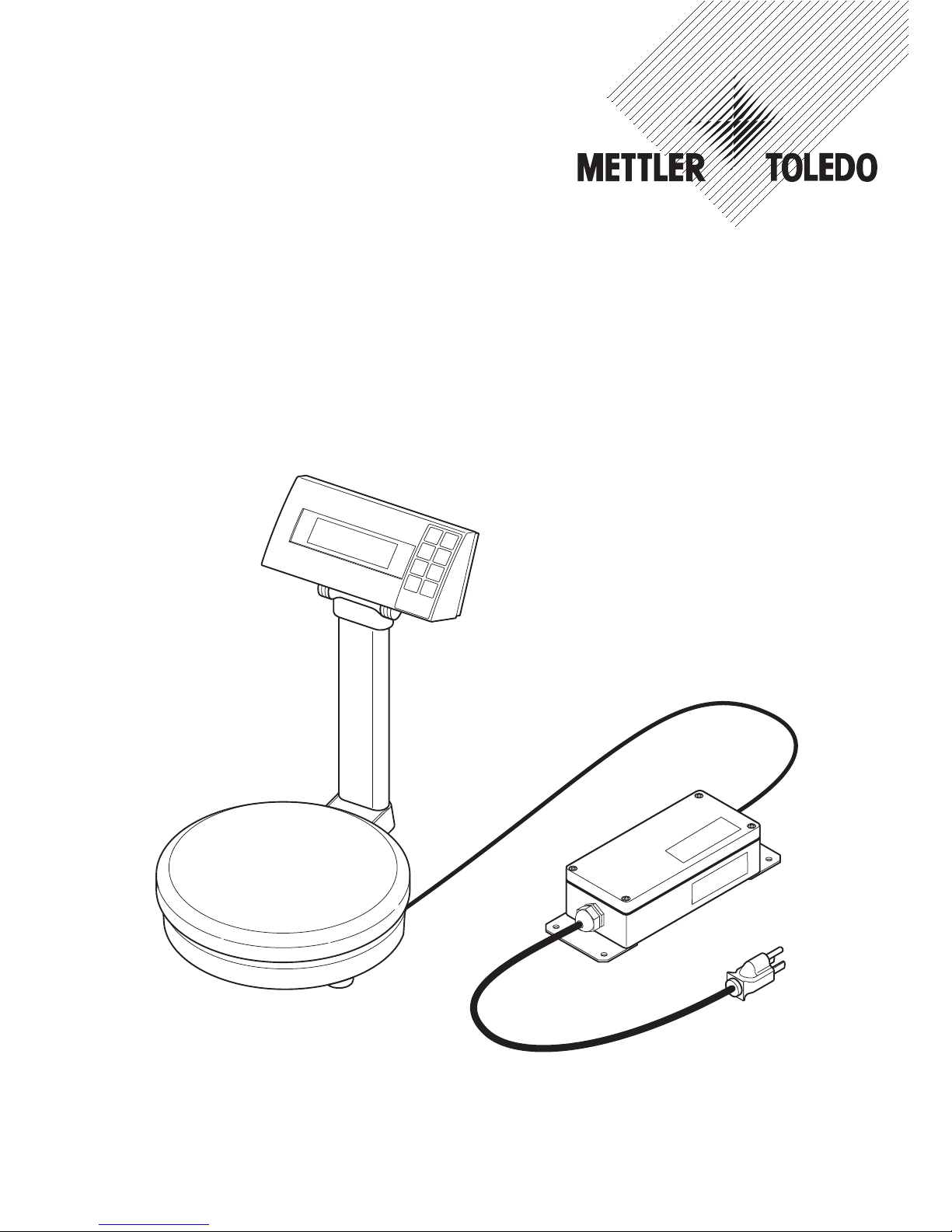
PS7-X Paint Mixing Scales with PS-EX1 Power Supply Unit
Farbmischwaagen PS7-X mit Speisegerät PS-EX1
M
E
T
T
L
E
R
T
O
L
E
D
O
+
Y
e
s
U
n
it
M
e
n
u
F
a
c
to
r
Mode
Enter
O/T
On/Off
–
N
o
Last
Comp
Next
Comp
P
S
7
m
a
x
.
7
1
0
0
g
d
=
0
.
1
g


Contents / Inhaltsverzeichnis
1 Documentation for the PS7-X Paint Mixing Scale with
PS-EX1 Power Supply Unit ............................................................. 5
2 Application range ..........................................................................5
3 Cautionary notes regarding installation ............................................6
4 Installation on the scale .................................................................6
4.1 Attaching power cable to the scale .................................................. 6
4.2 Ensuring admissibility of the peripheral unit ..................................... 7
4.3 Attaching peripheral unit ................................................................7
5 Installation of the PS-EX1 Power Supply Unit ....................................8
5.1 Installation in the safe area ............................................................8
5.2 Installation in the hazardous area of zone 2 ..................................... 9
6 Operation and maintenance ......................................................... 10
6.1 Safety measures during operation ................................................. 10
6.2 Control....................................................................................... 10
6.3 Cleaning .................................................................................... 10
7 Directives and test standards ........................................................ 10
8 Technical data ............................................................................11
9 FCC and Canadian EMC reglementation ......................................... 12
English
1 Unterlagen zur Farbmischwaage PS7-X mit Speisegerät PS-EX1 .......13
2Einsatzbereich ............................................................................ 13
3 Sicherheitshinweise zur Installation ............................................... 14
4 Installation an der Waage ............................................................ 14
4.1 Speisekabel an der Waage anschliessen ....................................... 14
4.2 Zulässigkeit des Peripheriegeräts sicherstellen ................................15
4.3 Peripheriegerät anschliessen ........................................................ 15
5 Installation des Speisegeräts PS-EX1 ............................................. 16
5.1 Installation im sicheren Bereich .................................................... 16
5.2 Installation in explosionsgefährdeter Umgebung der Zone 2 ............. 17
6 Betrieb und Wartung.................................................................... 18
6.1 Sicherheitsmassnahmen im Betrieb ............................................... 18
6.2 Kontrolle .................................................................................... 18
6.3 Reinigung ..................................................................................18
7 Direktiven und Prüfnormen ...........................................................18
8Technische Daten ........................................................................ 19
I Anschlussplan/Installation Drawing CENELEC 21201489 / 230 V .... 20
II US Control Drawing 21201484A .................................................. 21
III Installation Drawing for Canada 21202517A
Dessin d’installation pour le Canada ............................................. 22
Deutsch

4

5
1 Documentation for the PS7-X Paint Mixing Scale with
PS-EX1 Power Supply Unit
The PS7-X Paint Mixing Scale with the PS-EX1 Power Supply Unit is accompanied by the
following documentation:
• Installation and maintenance instructions
• Operating instructions
These installation and maintenance instructions apply to all scales with a type designation
containing the letters PS7-X. The individual model designations may also include numbers
detailing the weighing range and additional letters which indicate special versions.
These instructions contain information for the installation and start-up of the scale and the
power supply unit, as well as all requirements necessary for safe operation of the system.
You will find all information on the weighing applications and the interface operation in the
operating instructions.
2 Application range
The PS7-X Paint Mixing Scales are approved for use in a hazardous area classified as
zone 1 or zone 2, gas group IIB and temperature class T4. Then, they are FMRC and CSA
approved to the classification: Class 1, Division 1, Group CD.
The PS-EX1 Power Supply Unit must be installed in the safe area. If local installation
regulations permit, the power supply unit may also be installed in zone 2. Installation in
US Division 2 is not approved.
The RS232 interface built in the scale is intrinsically safe.
The only peripherals which may be attached are those fitted with an interface having the
same limiting values and approved as intrinsically safe, see section "Technical data".

6
3 Cautionary notes regarding installation
▲ Perform the installation only as de-
scribed in these instructions and in the
appropriate control drawing.
▲ It is essential to comply with national
regulations regarding grounding and
connection to the power supply.
4 Installation on the scale
▲ In all installation work, refer to the appropriate control drawing:
– Installation drawing PS-EX1 21201489 / 230 V according to CENELEC
– Control drawing 21201484A for USA
– Installation drawing 21202517A for Canada
4.1 Attaching power cable to the scale
• Turn the scale on its side so that the
connection socket (1) on the bottom is
accessible.
• Route the blue cable from the PS-EX1
Power Supply Unit to the scale and plug
connector into the scale.
• Use a grounding cable (cross-section
≥ 1mm2) to connect the grounding
screw (2) to the nearest connection of the
grounding system of the building electrical installation.
• Turn the scale back to the upright position.
▲ No changes whatsoever may be made to the scale or the power supply unit.
▲ Service work and repairs must be carried out only by personnel authorized by METTLER
TOLEDO.
▲ Check that the scale and power supply unit are in perfect condition with regard to safety
before putting into operation for the first time and at least after every 3 years of service.
12

7
4.2 Ensuring admissibility of the peripheral unit
If a peripheral unit needs to be connected, its RS232 interface must also be intrinsically safe
and approved to maintain the intrinsic safety.
• Ensure that the electrical limiting values of the peripheral match the limiting values printed
on the scale next to the socket.
If this is not the case, install an approved barrier, e.g. MTL 7061 Pac or 7161 Pac.
4.3 Attaching peripheral unit
• Connect the cable from the peripheral
device to the 9-pin I/O socket (3) of the
scale. Fix all connectors by tightening
screws.
3
8
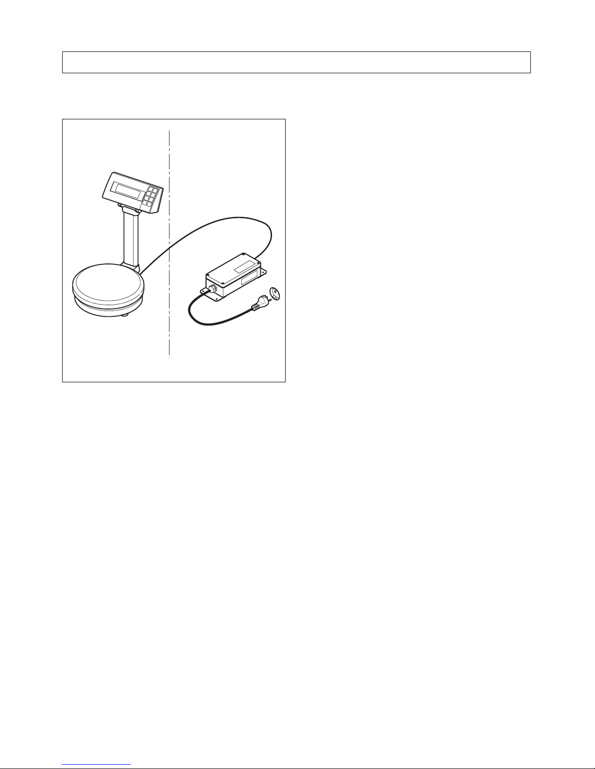
5 Installation of the PS-EX1 Power Supply Unit
5.1 Installation in the safe area
• Install the power supply in the safe area
near a wall socket.
If required, the power supply unit can be
permanently fixed by using the mounting
plates and the 4 screws.
• Route the power line cable and the cable
to the scale so that they are protected
against damage. Cables must not be
kinked or bent at sharp angles.
• Plug the power plug into the wall socket
of the building electrical installation.
Note: The type 21201489 of the PS-EX1
(230 V Euro) is delivered without plug. Fit a
3-pole plug to the cable observing the lead
colors:
yellow/green lead ground
brown lead phase
blue lead neutral
As neither the power supply unit nor the
scale have an on/off switch, the power plug
serves as a power disconnecting device.
The scale is ready for operation as soon as
the power plug is plugged in.
M
ETTLER TOLEDO
+
Y
e
s
U
n
i
t
M
e
n
u
F
a
c
to
r
M
o
d
e
E
n
te
r
O/T
O
n/Off
–
N
o
L
a
s
t
C
o
m
p
N
e
x
t
C
o
m
p
P
S
7
m
a
x
.
7
1
0
0
g
d
=
0
.
1
g
Hazardous area
Safe area
230 V Euro
120 V US
 Loading...