

Mettler Toledo PS60, PS6L, PS2+ Technical Manual

PS
Shipping Scales
PS60
PS6L
PS2+
Technical/Operator
Manual
For PS units with
GEOCAL™
A15402600A
03/01

©Mettler-Toledo, Inc. 2000
No part of this manual may be reproduced or transmitted in any form or by any means,
electronic or mechanical, including photocopying and recording, for any purpose without
the express written permission of Mettler-Toledo, Inc.
U.S. Government Restricted Rights: This documentation is furnished with Restricted Rights.

METTLER TOLEDO
Publication Problem Report
If you find a problem with our documentation, please complete and fax this form to (864) 472-7575
Publication Name:
Publication Part Number: Publication Date:
PROBLEM(S) TYPE: DESCRIBE PROBLEM(S):
!
Technical
!
Text
Illustration
!
Accuracy
!
Completeness
What information is
missing?
!
Clarity
What is not clear?
Procedure/step
!
Example
!
Explanation
!
Illustration ! Definition
!
Guideline
!
Other (please explain below)
!
Feature
!
INTERNAL USE
ONLY
Info. in manual
!
Info. not in
!
manual
!
Sequence
What is not in the right
order?
!
Other Comments
Use another sheet for
additional comments.
Your Name: Location:
Phone Number: ( )
Fax this completed form to MTSP at (864) 472-7575
Mettler-Toledo, Inc. Printed in U.S.A. A14981600A


INTRODUCTION
This publication is provided as a guide for individuals in the operation, use, and care of this
METTLER TOLEDO product.
Further information or assistance regarding this product may be obtained by writing to:
METTLER TOLEDO
1900 Polaris Parkway
Columbus, OH 43240-2020
(614) 438-4400
WARNING!
This equipment generates, uses, an can radiate radio frequency energy and if not installed and
used properly, i.e., in accordance with the instructions manual, may cause harmful
interference to radio communications. It has been tested and found to comply with the limits
for a Class A computing device pursuant to Subpart J of Part 15 of FCC Rules, which are
designed to provide reasonable protection against such interference when operated in a
commercial environment. Operation of this equipment in a residential area may cause
interference, in which case the user at his own expense will be required to take whatever
measures may be required to correct the interference.
METTLER TOLEDO RESERVES THE RIGHT TO MAKE
REFINEMENTS OR CHANGES WITHOUT NOTICE.
PRECAUTIONS
READ this manual BEFORE
operating or servicing this
equipment.
FOLLOW these instructions
carefully.
SAVE this manual for future
reference.
DO NOT allow untrained
personnel to operate, clean,
inspect, maintain, service, or
tamper with this equipment.
WARNING
DISCONNECT ALL POWER TO THIS UNIT
BEFORE INSTALLING, SERVICING, CLEANING,
OR REMOVING THE FUSE. FAIL UR E TO DO SO
COULD RESULT IN BODILY H ARM AND/OR
PROPERTY DAMAGE.
CAUTION
OBSERVE PRECAUTIONS FOR
HANDLING ELECTROSTATIC
SENSITIVE DEVICES.
ALWAYS DISCONNECT
this equipment from the
power source before
cleaning or performing
maintenance.
CALL METTLER TOLEDO
for parts, information, and
service.
Note: If the unit has been stored or
transported in below freezing
temperatures, allow the unit to warm
up to room temperature before turning
on AC power.
WARNING
ONLY PERMIT QUALIFIED PERSONNEL TO
SERVICE THIS EQUIPMENT. EXERCISE CARE
WHEN MAKING CHECKS, TESTS AND
ADJUSTMENTS THAT MUST BE MADE WITH
POWER ON. FAILING TO OBSERVE THESE
PRECAUTIONS CAN RESULT IN BODILY HARM.
WARNING
FOR CONTINUED PROTECTION AGAINST
SHOCK HAZARD, CONNECT TO PROPERLY
GROUNDED OUTLET ONLY. DO NOT REMOVE
THE GROUND PRONG.
CAUTION
BEFORE CONNECTING OR DISCONNECTING ANY INTERNAL
ELECTRONIC COMPONENTS OR INTERCONNECTING WIRING
BETWEEN ELECTRONIC EQUIPMENT, ALWAYS REMOVE POWER
AND WAIT AT LEAST THIRTY (30) SECONDS BEFORE ANY
CONNECTIONS OR DISCONNECTION’S ARE MADE. FAILURE TO
OBSERVE THESE PRECAUTIONS COULD RESULT IN DAMAGE TO
OR DESTRUCTION OF THE EQUIPMENT, OR BODILY HARM.

CONTENTS
1111 Introduction
2222 Installation and Calibration
3333 Configuring the Setup Parameters
Introduction................................
IntroductionIntroduction
Standard Features
Standard Features................................
Standard FeaturesStandard Features
Optional Accessories
Optional Accessories................................
Optional AccessoriesOptional Accessories
Specifications
Specifications................................
SpecificationsSpecifications
Standards Compliance
Standards Compliance................................
Standards ComplianceStandards Compliance
Installation and Calibration................................
Installation and CalibrationInstallation and Calibration
Unpacking and Setup
Unpacking and Setup................................
Unpacking and SetupUnpacking and Setup
Basic Information
Basic Information ................................
Basic InformationBasic Information
Initial Calibration using GEOCAL™
Initial Calibration using GEOCAL™................................
Initial Calibration using GEOCAL™Initial Calibration using GEOCAL™
Full Calibration
Full Calibration................................
Full CalibrationFull Calibration
Metrological Seal Installation
Metrological Seal Installation ................................
Metrological Seal InstallationMetrological Seal Installation
Configuring the Setup Parameters ................................
Configuring the Setup ParametersConfiguring the Setup Parameters
Basic Information
Basic Information ................................
Basic InformationBasic Information
Configuring Setup Parameters
Configuring Setup Parameters................................
Configuring Setup ParametersConfiguring Setup Parameters
................................................................
................................................................
................................................................
................................................................
................................................................
................................................................
................................................................
................................................................
Physical Dimensions.....................................................................................................................1-2
Power Requirements.....................................................................................................................1-3
Environmental Requirements........................................................................................................1-3
................................................................
................................................................
Electrical Interfaces ......................................................................................................................1-5
................................................................
................................................................
Installation.....................................................................................................................................2-1
................................................................
................................................................
The Display...................................................................................................................................2-4
Keys and Navigation.....................................................................................................................2-5
Power up Sequence.......................................................................................................................2-8
................................................................
................................................................
................................................................
................................................................
................................................................
................................................................
Program Block Access..................................................................................................................3-1
Exit Setup......................................................................................................................................3-1
................................................................
................................................................
Push Button Zero Program Block.................................................................................................3-2
Zero Cursor Program Block..........................................................................................................3-3
Power-up Unit Program Block......................................................................................................3-3
Build Program Block ....................................................................................................................3-3
Alternate Units Program Block.....................................................................................................3-4
Mode Program Block....................................................................................................................3-4
Filter Program Block.....................................................................................................................3-5
Baud Program Block.....................................................................................................................3-5
ASCII Program Block...................................................................................................................3-5
Parity Program Block....................................................................................................................3-6
Stop Program Block......................................................................................................................3-6
Protocol Program Block................................................................................................................3-6
Sleep Program Block ....................................................................................................................3-7
GEOCAL™ Program Block.........................................................................................................3-7
Calibration Program Block...........................................................................................................3-7
End Program Block.......................................................................................................................3-8
................................................................
................................................................
................................................................
................................................................
................................................................
................................................................
................................................................
................................................................
................................................................
................................................................
................................................................
................................................................
..................................................
................................................................
................................................................
................................................................
...........................................
................................................................
................................................................
................................................................
................................................................
................................................................
.....................................................
................................................................
................................................................
................................................................
...........................................................
................................................................
................................................................
................................................................
................................................................
................................................................
...........................................................
................................................................
................................................
................................................................
................................1-1
................................................................
............................................
................................................................
........................................
................................................................
.....................................
................................................................
.......................................
................................................................
............................................
................................................................
........................... 2-10
......................................................
....................................3-1
................................................................
............................................
................................................................
........................... 3-2
......................................................
............ 1-1
........................
.................. 1-2
....................................
...........2-1
......................
............ 2-4
........................
..................... 2-6
..........................................
................ 2-8
................................
............ 3-1
........................
1-1
1-11-1
1-1
1-11-1
........ 1-2
1-2
................
1-21-2
1-2
1-21-2
..... 1-4
1-4
..........
1-41-4
2-1
2-12-1
....... 2-1
2-1
..............
2-12-1
2-4
2-42-4
2-6
2-62-6
2-8
2-82-8
2-10
2-102-10
3-1
3-13-1
3-1
3-13-1
3-2
3-23-2
4444 Operating Instructions
Operating Instructions................................
Operating InstructionsOperating Instructions
Keypad and Display
Keypad and Display................................
Keypad and DisplayKeypad and Display
Operator Functions
Operator Functions................................
Operator FunctionsOperator Functions
Parcel Weighing............................................................................................................................4-2
Unit Switching..............................................................................................................................4-2
Zeroing the Scale with an Empty Container.................................................................................4-2
................................................................
................................................................
................................................................
................................................................
................................................................
................................................................
................................................................
................................................................
................................................................
................................................................
..................................................
................................................................
.........................................
................................................................
...........................................
................................................................
..................4-1
....................................
........... 4-1
......................
4-1
4-14-1
......... 4-1
..................
4-1
4-14-1
4-1
4-14-1

Repowering from Sleep................................................................................................................ 4-3
5555 Service and Maintenance
6666 Parts and Accessories
Service and Maintenance................................
Service and MaintenanceService and Maintenance
Cleaning and Regular Maintenance
Cleaning and Regular Maintenance................................
Cleaning and Regular MaintenanceCleaning and Regular Maintenance
Troubleshooting
Troubleshooting................................
TroubleshootingTroubleshooting
Error Code Section....................................................................................................................... 5-2
Wall Transformer......................................................................................................................... 5-2
Main PCB..................................................................................................................................... 5-2
Blank or Half Display .................................................................................................................. 5-3
No Keypad Interaction................................................................................................................. 5-3
Indicator Locked .......................................................................................................................... 5-3
Load Cell Replacement
Load Cell Replacement................................
Load Cell ReplacementLoad Cell Replacement
Installing the Battery Kit
Installing the Battery Kit ................................
Installing the Battery KitInstalling the Battery Kit
Installing the Base Mount Display
Installing the Base Mount Display ................................
Installing the Base Mount DisplayInstalling the Base Mount Display
Installing the Ball Top Transfer Platter
Installing the Ball Top Transfer Platter................................
Installing the Ball Top Transfer PlatterInstalling the Ball Top Transfer Platter
Parts and Accessories................................
Parts and AccessoriesParts and Accessories
PS60/PS6L Scale Parts
PS60/PS6L Scale Parts ................................
PS60/PS6L Scale PartsPS60/PS6L Scale Parts
PS6L Parts List
PS6L Parts List................................
PS6L Parts ListPS6L Parts List
PS2+ Scale Parts
PS2+ Scale Parts................................
PS2+ Scale PartsPS2+ Scale Parts
PS2+ Parts List
PS2+ Parts List ................................
PS2+ Parts ListPS2+ Parts List
Weight Display Parts
Weight Display Parts................................
Weight Display PartsWeight Display Parts
................................................................
................................................................
................................................................
................................................................
................................................................
................................................................
................................................................
................................................................
................................................................
................................................................
................................................................
................................................................
................................................................
................................................................
................................................................
................................................................
................................................................
................................................................
................................................................
................................................................
................................................................
................................................................
................................................................
................................................................
................................................................
................................................................
................................................................
................................................................
................................................................
................................................................
................................................................
................................................................
................................................................
................................................................
................................................................
................................................................
................................................................
................................................................
................................................................
................................................................
................................................................
................................................................
.............................................
................................................................
....................................................
................................................................
...............................................
................................................................
.....................................
................................................................
....................................
................................................................
......................................................
................................................................
.................................................
................................................................
.................................................
................................................................
....................................
................................................................
................................................
................................................................
.............................................
................................................................
...............................................
................................................................
........................................
................................................................
....................5-1
........................................
......................5-7
............................................
................. 6-1
..................................
............. 5-1
..........................
...............5-1
..............................
.................5-8
..................................
................6-3
................................
.............6-4
..........................
...............6-5
..............................
5-1
5-15-1
5-1
5-15-1
5-1
5-15-1
.....5-3
5-3
..........
5-35-3
....5-3
5-3
........
5-35-3
5-7
5-75-7
5-8
5-85-8
6-1
6-16-1
....6-2
6-2
........
6-26-2
6-3
6-36-3
6-4
6-46-4
6-5
6-56-5
........6-6
6-6
................
6-66-6
Appendix: Host Interface
Appendix: Host Interface................................
Appendix: Host InterfaceAppendix: Host Interface
Communication Parameters
Communication Parameters................................
Communication ParametersCommunication Parameters
Protocols
Protocols................................
ProtocolsProtocols
Scale Status Byte Format
Scale Status Byte Format................................
Scale Status Byte FormatScale Status Byte Format
Scale Confidence Byte Format
Scale Confidence Byte Format................................
Scale Confidence Byte FormatScale Confidence Byte Format
Calibrate Using Host Interface
Calibrate Using Host Interface................................
Calibrate Using Host InterfaceCalibrate Using Host Interface
Configure Scale Parameters Using Host Interface
Configure Scale Parameters Using Host Interface................................
Configure Scale Parameters Using Host InterfaceConfigure Scale Parameters Using Host Interface
................................................................
................................................................
................................................................
................................................................
................................................................
................................................................
................................................................
................................................................
ASCII Characters and Conversions.....................................................................................2
Toledo Protocol Host Commands.......................................................................................4
................................................................
................................................................
................................................................
................................................................
................................................................
................................................................
..........................................................
................................................................
................................................................
................................................................
...........................................................
................................................................
................................................................
................................................................
...............................................................
................................................................
...............................................................
................................................................
................................................................
................................................................
.......................... 1111
....................................................
....................................1111
................................................................
...........................1111
......................................................
......................................
................................................................
...............................5555
..............................................................
...............................6666
..............................................................
.....................................
................................................................
......5555
............
.....7777
..........

1
1
11
Chapter 1:
Chapter 1: Introduction
Chapter 1: Chapter 1:
Introduction
Introduction
IntroductionIntroduction
Thank you for purchasing a PS shipping scale from METTLER TOLEDO.
The legal-for-trade model of the PS60 shipping scale is a low-profile, 150 ×
0.05 lb (60 × 0.02 kg) capacity scale designed to meet the needs of the legalfor- trade parcel/manifest markets. The PS60 also features an auto-ranging
and/or weight classifying version with a capacity of 0 - 60 lb × .02 lb / 60 150 lb × .05 lb. Both are NTEP approved. (See Chapter 3 for a complete list
of builds.)
The legal-for-trade model of the PS6L shipping scale is similar to the PS60
but has a higher resolution for letter weighing. It has a weight classifying,
auto-ranging capacity of 0-7 lb x 0.1oz / 7-70 lb x 0.2 oz / 70–149 lb x 0.5 oz.
The PS2+ model is a large roller top scale with a capacity of 250 x 0.1 lb
(100kg x 0.05kg). It is designed for parcel weighing in conveyor systems.
Introduction
IntroductionIntroduction
Standard Features
Standard Features
Standard FeaturesStandard Features
Standard Features
Standard Features
Standard FeaturesStandard Features
The PS, like all METTLER TOLEDO products is designed for maximum
durability and reliability in even the most demanding application
environments. The PS is manufactured in one of METTLER TOLEDO’s ten
ISO 9000 certified facilities so you are assured to receive a high-quality
product.
The scale is designed for use in parcel shipping and other light industrial
environments. This unit is not intended for wash-down or hazardous area
operation, or for operation in environments of extreme dust, heat, cold, or
humidity.
In the unlikely event you experience difficulties operating your scale, please
contact your local distributor or METTLER TOLEDO representative from
whom you purchased the scale.
The following are standard features built into each PS shipping scale.
• 150 lb or 250 lb capacity “Eagle+” load cell
• Die-cast aluminum base and sub-platter
• Stainless steel or plastic platter
• RS-232 serial interface to the scale base
• Automatic power down mode for energy conservation
• 12 VDC, 60mA power supply unit (wall-mount transformer)
• 2-key weight indicator
(03/01)
(03/01) 1-1
(03/01) (03/01)
1-1
1-11-1
METTLER TOLEDO PS Shipping Scale Technical/Operators Manual
METTLER TOLEDO PS Shipping Scale Technical/Operators Manual
METTLER TOLEDO PS Shipping Scale Technical/Operators ManualMETTLER TOLEDO PS Shipping Scale Technical/Operators Manual
Optional Accessories
Optional Accessories
Optional AccessoriesOptional Accessories
• 0270, 2-key weight indicator base mount display with 12 in. cable
• D-cell alkaline battery kit (for some models)
• Tower display with 14 ft cable
• Ball transfer top platter (standard on PS2+)
• Car lighter jack
• Wall mount display with 14 ft cable
• Dual wall mount displays with 6 ft cable
Specifications
Specifications
SpecificationsSpecifications
The PS shipping scale conforms to and operates best within the specifications
described in this section.
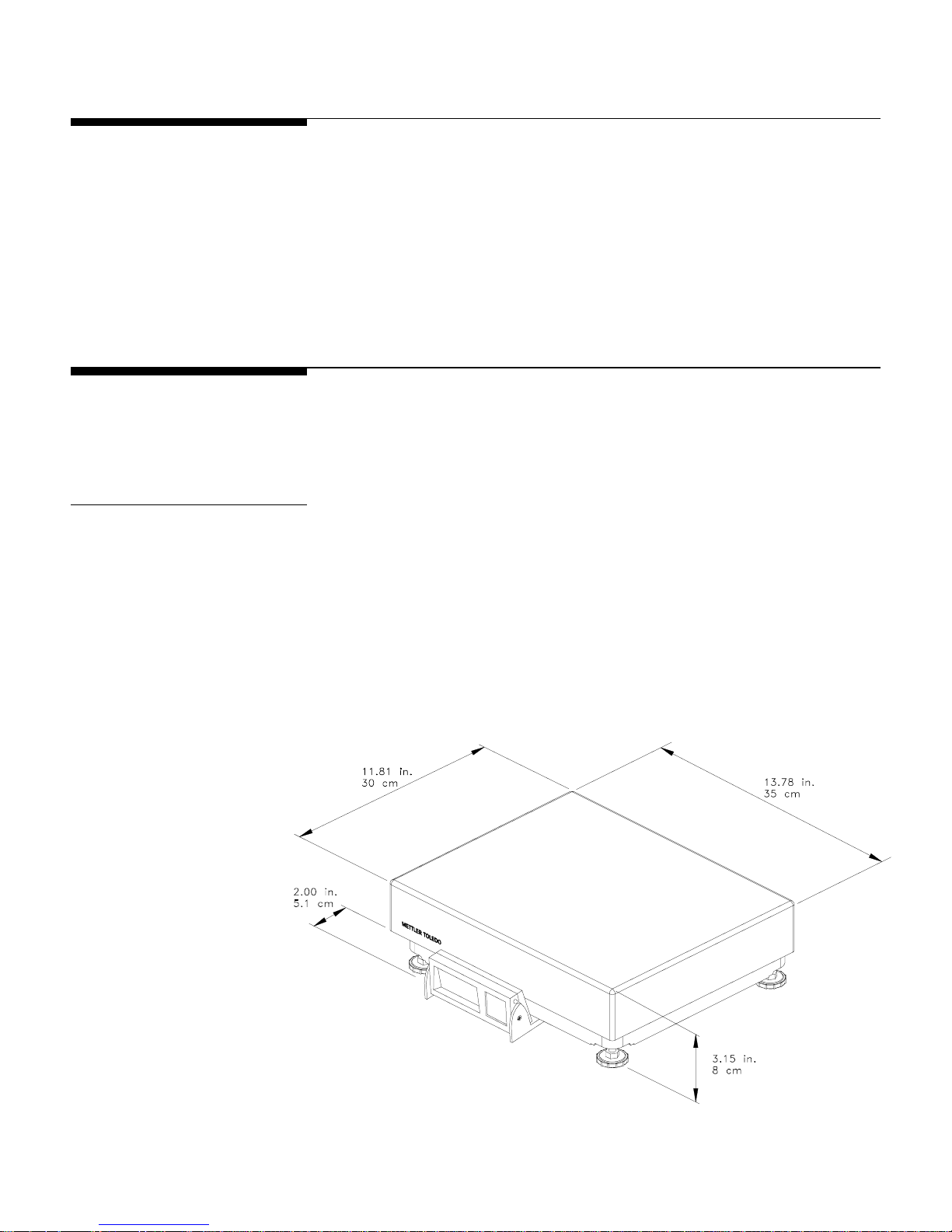
Physical Dimensions
Physical Dimensions
Physical DimensionsPhysical Dimensions
• Base dimensions: 29 cm × 33.5 cm (11.42 in. × 13.19 in.)
• Platter dimensions: 30 cm × 35 cm (11.81 in. × 13.78 in.)
• Maximum dimensions w/indicator: 35.1 cm × 35 cm (14.09 in. × 13.78 in.)
• Height with platter: 8 cm (3.15 in.)
• Height with platter and battery: 9 cm (3.54 in.)
• Weight with display: 6.65 kg (14.7 lb.)
• Weight with display and battery: 7.75 kg (17.1 lb)
• Shipping weight: 10 kg (22.0 lb)
1-2
1-2 (03/01)
(03/01)
1-21-2
(03/01) (03/01)
Figure
Figure 1111----aaaa: PS60 / PS6L Dimensions
Figure Figure
: PS60 / PS6L Dimensions
: PS60 / PS6L Dimensions: PS60 / PS6L Dimensions
Chapter 1:
Chapter 1: Introduction
Chapter 1: Chapter 1:
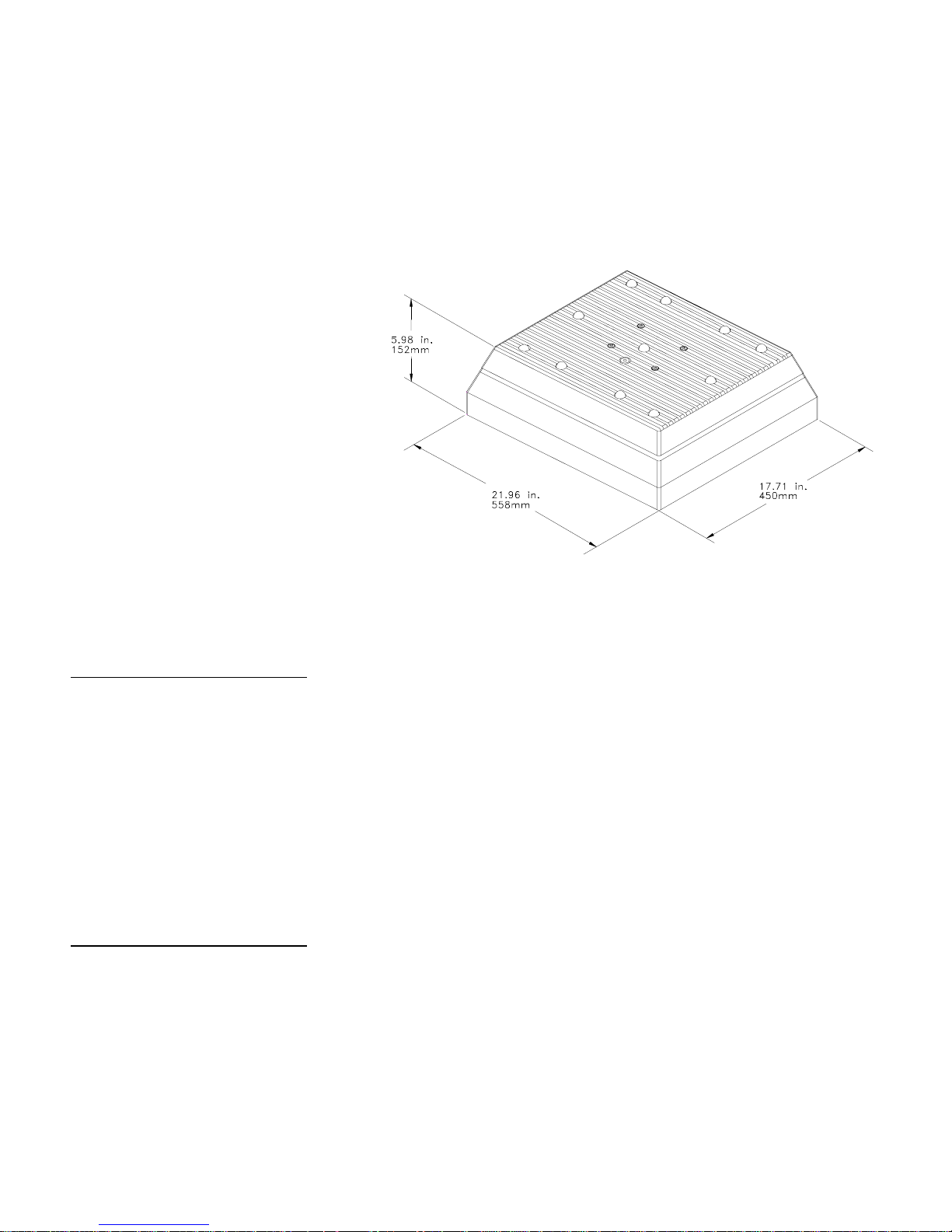
• Base dimensions: 558 mm × 450 mm (21.96 in. × 17.71 in.)
• Platter dimensions: 489 mm × 387mm (19.25 in. × 15.24 in.)
• Height with platter: 152 mm (5.98 in.)
• Weight: 16.8 kg (37.0 lb.)
• Shipping weight: 19 kg (41.9 lb.)
Introduction
IntroductionIntroduction
Specifications
Specifications
SpecificationsSpecifications
Power Requirements
Power Requirements
Power RequirementsPower Requirements
Environmental
Environmental
EnvironmentalEnvironmental
Requirements
Requirements
RequirementsRequirements
Figure
Figure 1111-b: PS2+ Dimensions
Figure Figure
The PS operates within an input voltage range of 7.5 to 15 VDC (at 60 mA).
• An external, wall mount 12 VDC voltage converter supplies power to the
PS.
• An optional D-cell battery kit can be used to power the scale continuously
for at least 40 hours. Battery life is extended with the on/off switch in the
“off” position.
• An optional 12 VDC Car Lighter Jack Cable can power the PS.
The PS60 operating range is −10° to +40°C (+14°F to +104°F) at 10 to 90%
relative humidity, non-condensing. The PS6L & PS2+ operation range is
+10° to +40°C at 10 to 90% relative humidity, non-condensing. The shipping
and storage temperature range is −20° to +60°C (-4°F to +140°F) at 0 to 95%
relative humidity, non-condensing.
-b: PS2+ Dimensions
-b: PS2+ Dimensions-b: PS2+ Dimensions
(03/01)
(03/01) 1-3
(03/01) (03/01)
1-3
1-31-3

METTLER TOLEDO PS Shipping Scale Technical/Operators Manual
METTLER TOLEDO PS Shipping Scale Technical/Operators Manual
METTLER TOLEDO PS Shipping Scale Technical/Operators ManualMETTLER TOLEDO PS Shipping Scale Technical/Operators Manual
The scale is designed for use in parcel shipping and other light industrial
environments. This unit is not intended for wash-down or hazardous area
operation, or for operation in environments of extreme dust, heat, cold, or
humidity.
Standards Compliance
Standards Compliance
Standards ComplianceStandards Compliance
The PS60 meets or exceeds USA NIST HB-44, Australian NSC Document
100, Canadian MC, European Community EN 45501, and OIML R76 for a
3000 divison, Class III parcel scale. The Product also conforms to relevant
CE product requirements.
The PS6L meets or exceeds USA NIST HB-44 requirements for a 4800
division, Class III parcel scale.
Both the PS60 and PS6L have been tested and found to comply with the limits
for a Class A computing device pursuant to Subpart J of Part 15 of FCC
Rules.
1-4
1-4 (03/01)
(03/01)
1-41-4
(03/01) (03/01)
Electrical Interfaces
Electrical Interfaces
Electrical InterfacesElectrical Interfaces
Chapter 1:
Chapter 1: Introduction
Chapter 1: Chapter 1:
Standards Compliance
Standards Compliance
Standards ComplianceStandards Compliance
Introduction
IntroductionIntroduction
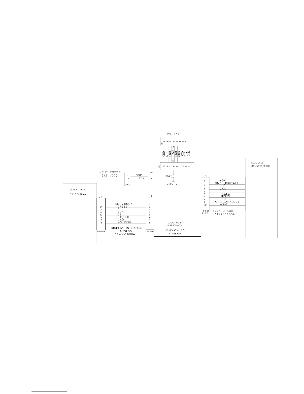
The PS scale’s single board construction has a load cell connector (10 position
ZIF), display connector (8 position phone jack), RS-232 interface (9-Pin
DSUB), and an input power jack. The following interconnection diagram
describes wiring connections for the PS shipping scale.
The PS can function as a peripheral device to a host through the RS-232 serial
port. Calibration and setup can be done using the Host Interface command set.
For detailed instructions describing calibration and setup using the Host
Interface, please refer to the Appendix at the end of this manual.
Figure
Figure 1111-c: PS Electronic Interface Diagram
Figure Figure
-c: PS Electronic Interface Diagram
-c: PS Electronic Interface Diagram-c: PS Electronic Interface Diagram
(03/01)
(03/01) 1-5
(03/01) (03/01)
1-5
1-51-5


.
2
2
22
Unpacking and Setup
Unpacking and Setup
Unpacking and SetupUnpacking and Setup
If you choose to dispose of the
package, please recycle the
materials.
Chapter 2
Chapter 2: Installation and Calibration
Chapter 2Chapter 2
Installation and Calibration
Installation and Calibration
Installation and CalibrationInstallation and Calibration
This chapter gives detailed instructions and important information you will
need to install the PS successfully. Please read this chapter thoroughly before
you begin installation. This information is also covered in the PS Operator
Instructions.
Please inspect the package as the carrier delivers it.
If the shipping container is damaged, check for internal damage and file a
•
freight claim with the carrier if necessary.
If the container is undamaged, open the box, remove the scale, and place it
•
on a solid, flat surface.
Please keep the packing material and shipping insert in case the scale needs to
be returned to METTLER TOLEDO. The PS is a precision instrument and
may be permanently damaged if not shipped in factory-approved packaging.
: Installation and Calibration
: Installation and Calibration: Installation and Calibration
Unpacking and Setup
Unpacking and Setup
Unpacking and SetupUnpacking and Setup
Installation
Installation
InstallationInstallation
The proper environment enhances the
operation and longevity of the scale.
Typical package contents for the PS include:
PS Shipping Scale
•
Installation Instructions
•
Power Supply
•
Optional Accessories
•
The PS shipping scale is fully assembled at the factory, and you should not
have to assemble the unit. To install components other than those installed at
the factory, please refer to Chapter 5 Service and Maintenance.
Locate a suitable environment for the scale. Refer to Chapter 1 for
1.
1.
1.1.
environmental specifications.
Remove the packaging material from each side of the scale. Remove the
2.
2.
2.2.
scale by grasping the bottom sides of the scale.
grasping the sub-platter.
Place the scale on a sturdy, level surface and remove any protective
3.
3.
3.3.
shipping materials under the platter.
Do not
lift the scale by
(03/01) 2-
(03/01) 2-1111
(03/01) 2-(03/01) 2-

METTLER TOLEDO PS Shipping Scale Technical/Operators Manual
METTLER TOLEDO PS Shipping Scale Technical/Operators Manual
METTLER TOLEDO PS Shipping Scale Technical/Operators ManualMETTLER TOLEDO PS Shipping Scale Technical/Operators Manual
Level the scale by turning the adjustable feet on the bottom of the unit.
4.
4.
4.4.
When the bubble in the bubble indicator is within the circle, the PS is
level (see Figures 2-a, 2-b, 2-c). The feet must be adjusted so the scale
does not rock.
Leveling Feet (4)
M
E
T
T
L
E
R
U
N
T
I
O
T
L
V
V
S
E
D
O
O
N
-
/
O
O
F
F
Figure 2-
Figure 2-aaaa: PS and PS6L Leveling Feet
Figure 2-Figure 2-
: PS and PS6L Leveling Feet
: PS and PS6L Leveling Feet: PS and PS6L Leveling Feet
(03/01) 2-
(03/01) 2-2222
(03/01) 2-(03/01) 2-
Figure 2-b: PS2+ Leveling Feet
Figure 2-b: PS2+ Leveling Feet
Figure 2-b: PS2+ Leveling FeetFigure 2-b: PS2+ Leveling Feet
Chapter 2
Chapter 2: Installation and Calibration
Chapter 2Chapter 2
: Installation and Calibration
: Installation and Calibration: Installation and Calibration
Unpacking and Setup
Unpacking and Setup
Unpacking and SetupUnpacking and Setup
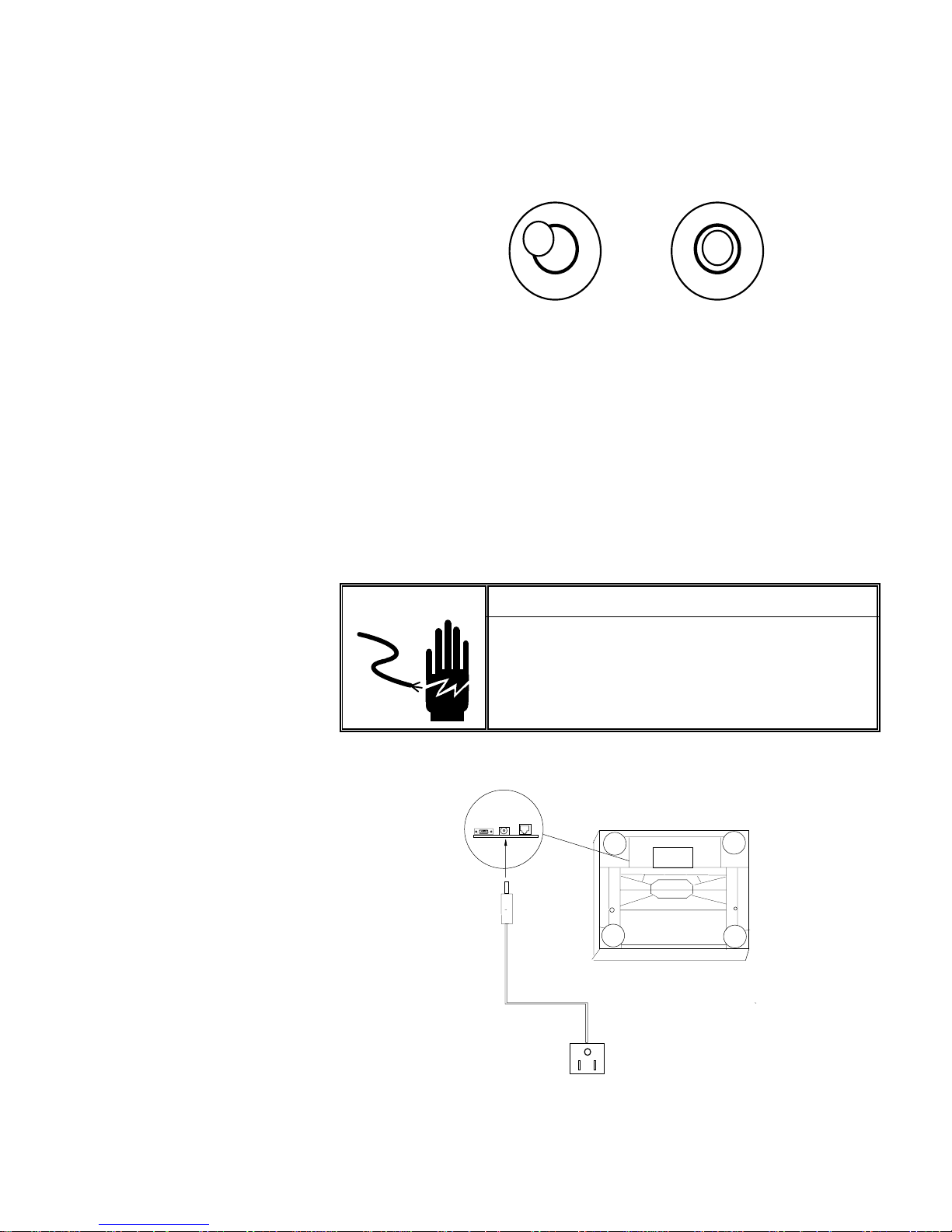
Incorrect
Bubble is not
within circle
Figure 2-c: Level Indicator
Figure 2-c: Level Indicator
Figure 2-c: Level IndicatorFigure 2-c: Level Indicator
Unpack the power supply and plug it into the power jack in the scale base.
5.
5.
5.5.
Correct
Bubble is
within circle
The jack is recessed on the bottom of the base toward the center front.
Plug the line cord into a
properly grounded
AC power outlet. Figure 2-d
illustrates proper power supply connection.
WARNING!
AC power sources must have proper short
circuit and over current protection in
accordance with local and national electrical
regulations. Failure to provide this may result
in bodily injury and/or property damage.
NOTE: Inside of barrel is positive.
Figure 2-d: Power Cable Connection
Figure 2-d: Power Cable Connection
Figure 2-d: Power Cable ConnectionFigure 2-d: Power Cable Connection
(03/01) 2-
(03/01) 2-3333
(03/01) 2-(03/01) 2-

METTLER TOLEDO PS Shipping Scale Technical/Operators Manual
METTLER TOLEDO PS Shipping Scale Technical/Operators Manual
METTLER TOLEDO PS Shipping Scale Technical/Operators ManualMETTLER TOLEDO PS Shipping Scale Technical/Operators Manual
Basic Information
Basic Information
Basic InformationBasic Information
The following sections describe some basic information that you will need to
know as you install, calibrate, and use the PS in normal operating mode.
The Display
The Display
The DisplayThe Display
The PS’s display consists of six digits and five cursor positions. Each digit is
composed of seven segments and is 12 mm high. The PS’s cursor can appear
above one or more of the legends printed on the display to indicate the current
unit, stable conditions, zero, or options in setup mode.
The display area also indicates over-capacity and under-capacity conditions.
Over- and under-capacity are indicated on the display as follows:
0><
Over Capacity
Over Capacity
Over CapacityOver Capacity
0
Under Capacity
Under Capacity
Under CapacityUnder Capacity
Figure 2-e: Over/Under Capacity Display
Figure 2-e: Over/Under Capacity Display
Figure 2-e: Over/Under Capacity DisplayFigure 2-e: Over/Under Capacity Di splay
><
(03/01) 2-
(03/01) 2-4444
(03/01) 2-(03/01) 2-
 Loading...