

Page 1
Operating Instructions
ParticleTrack G400
Real-Time Particle Characterization
Hardware Manual
Page 2

2
Hardware Manual
No part of this publication may be stored in a
retrieval system, transmitted, or reproduced in
any way, including but not limited to photocopy,
photograph, magnetic or other record, without
the prior written permission of Mettler-Toledo
AutoChem, Inc.
FBRM®, iC Process™, iC FBRM™, PVM™, and
iCPVM™ are trademarks of Mettler-Toledo
AutoChem, Inc.
Microsoft® and Windows® are either registered
trademarks or trademarks of Microsoft Corporation
in the United States and/or other countries.
All other brand and product names are trademarks
or registered trademarks of their respective owners.
The information in this publication is provided for
reference only. All information contained in this
publication is believed to be correct and complete.
Mettler-Toledo AutoChem, Inc. shall not be liable
for errors contained herein nor for incidental or
consequential damages in connection with the
furnishing, performance, or use of this material. All
product specifications, as well as the information
contained in this publication, are subject to change
without notice.
For technical support, email: AutoChemCustomerCare@mt.com
For updates, webinars, and the latest documents: http://community.autochem.mt.com
Mettler-Toledo AutoChem, Inc.
7075 Samuel Morse Drive
Columbia, MD 21046
www.mt.com/AutoChem
Tel: + 1 866.333.6822
Fax: +1 410.910.8600
This publication may contain or reference
information and products protected by copyrights
or patents and do not convey any license under
the patent rights of Mettler-Toledo AutoChem, Inc.,
nor the rights of others. Mettler-Toledo AutoChem,
Inc. does not assume any liability arising out of
any infringements of patents or other rights of third
parties.
Mettler-Toledo AutoChem, Inc. makes no warranty
of any kind with regard to this manual, including
but not limited to the implied warranties of
merchantability and fitness for a particular purpose.
04192 016
Page 3

3
1 Introduction
This manual covers specific safety and quality information relating to the
ParticleTrack™G400 with FBRM® (Focused Beam Reflectance Measurement) technology.
Throughout this manual, the system is referred to by the name: ParticleTrack G400 or
FBRM G400. The ParticleTrack G400 system includes the base unit and probe connected
by a flexible armored conduit.
ParticleTrack G400 is a probe-based instrument that is inserted directly into laboratory
reactors to track changing particle size and count in real time at full process
concentrations. Particles, particle structures, and droplets are monitored continuously,
as process parameters vary, providing scientists with the evidence required to deliver
consistent particles with the required attributes. A ParticleTrack G400 system has fixed
or interchangeable probe options and includes options for a single or dual-system
configuration. ParticleTrack G400 dual-system configurations can simultaneously
measure two small-scale vessels or points in a process stream. Click the link to see the
FBRM Method of Measurement video (requires internet connection).
www.mt.com/ParticleTrack G400
Contents
1 Introduction
2 Intended Use
3 Technical Data
4 Safety Information
5 Supplementary Documentation
6 Product Installation
7 Probe Mounting Options
8 Operating Instructions
9 Best Practices for Routine Operation
10 Troubleshooting
11 Product Maintenance
12 Disposal
Page 4
4
Hardware Manual
2 Intended Use
The system includes a power supply, laser and detector modules, and PCBs. The base
unit is fitted with a permanently attached flexible armored conduit, which is connected to
the process probe. The ParticleTrack G400 system is designed for indoor use.
The system may only be used in safe locations and is not certified for use in hazardous
locations.
3 Technical Data
Table 1. System certications and functional specications
System certications CE/NRTL-C Approved, Class 1 Laser Device, Compliant
with 21CFR1040.10 and 1040.11 and IEC 60825-1; IPX0
Functional specications
Method of Measurement Focused Beam Reectance Measurement (FBRM®)
Measurement range 0.5 to 2,000 µm
Scan speed 2 m/s (14 mm probe: 125 Hz)
1.2 m/s (19 mm probe: 75 Hz)
Page 5
5
Power On
Communication
HW Status
SW Status
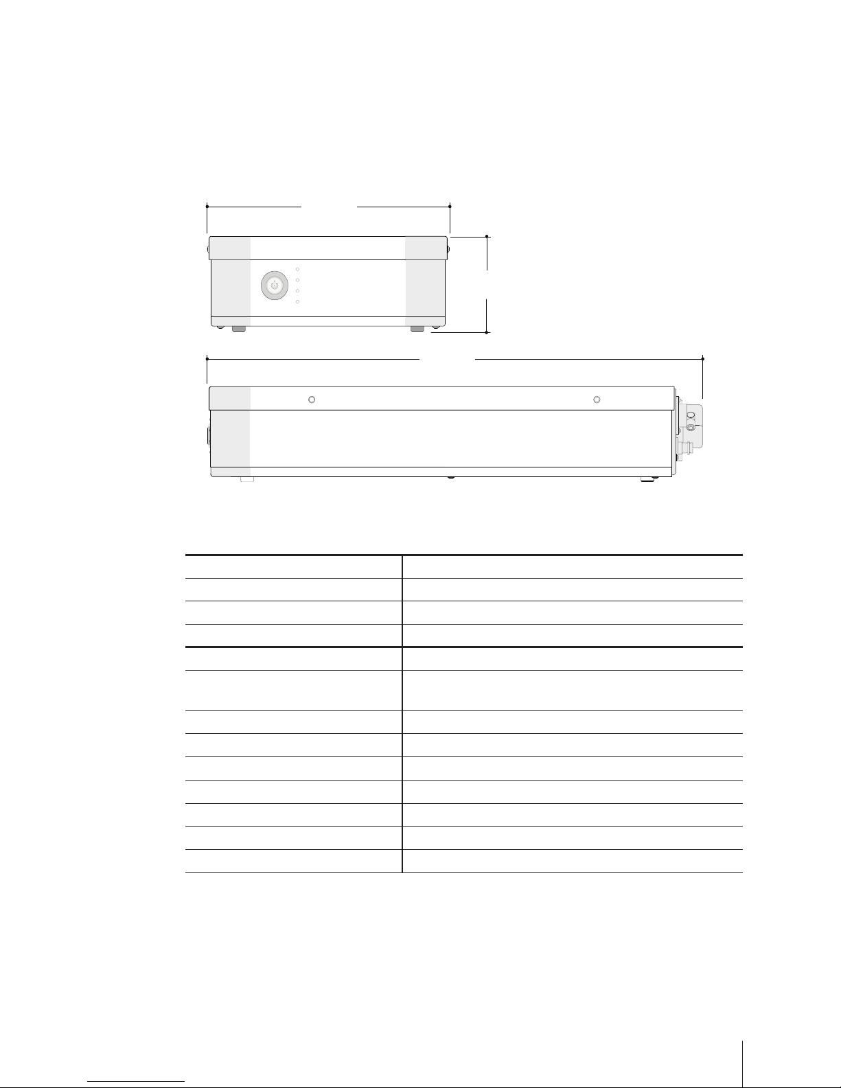
199 mm
[
7.83”
]
400 mm
[9.5”]
241 mm
[19.4”]
492 mm
32 mm
[
Ø 1.25”
]
19 mm
[
Ø 0.75”
]
199 mm
[
7.83”
]
70 mm
[
2.76”
]
[
15.57”
]
199 mm
[
7.83”
]
91 mm
[
3.6”
]
32 mm
[
Ø 1.25”
]
9.5 mm
[
Ø 0.38”
]
14 mm
[
Ø 0.55”
]
136 mm
[
5.35”
]
32 mm
[
Ø 1.25”
]
9.5 mm
[
Ø 0.38”
]
89 mm
[
3.5”
]
Figure 1. System Dimensions—Base unit
Environmental
Operating humidity range 0 to 85%
Operating temperature range 5 to 35 °C
General
Material of construction 14 ga Aluminum
with Class 3 RoHS-compliant chemical lm
Ingress protection IPX0
Power 100-240 VAC, 50/60 Hz, 1.2A
Weight
3.25 kg [7.17 lb]
Communication interface USB, 3 m [10 ft] cable
Pollution degree 2
Installation (overvoltage) category II
PCBs Fr–4
Base Unit Specifications
Table 2. Base unit specications
Page 6

6
Hardware Manual
199 mm
[
7.83”
]
400 mm
32 mm
[
Ø 1.25”
]
19 mm
[
Ø 0.75”
]
199 mm
[
7.83”
]
70 mm
[
2.76”
]
[
15.57”
]
32 mm
[
Ø 1.25”
]
9.5 mm
[
Ø 0.38”
]
14 mm
[
Ø 0.55”
]
136 mm
[
5.35”
]
Figure 2. Probe dimensions—G400 14 mm probe
14/9.5 mm 19 mm
Wetted materials of
construction
Probe tip Alloy C22 Alloy C22
Probe window Sapphire Sapphire
Probe window seals TM [Thermo-Mechanical
press-t] (standard)
Kalrez® 6375 (standard)
TM [Thermo-Mechanical
press-t] (optional)
Environmental
Operating pressure range * 3 barg (standard)
0 to 100 barg (optional, requires custom engineering design)
Operating temperature range +10 to 90 °C (standard)
–80 to 90 °C (TM seal and purge)
–10 to 90 °C (Kalrez® seal and purge)
Installation
Conduit length 3 m [9.8 ft] 3 m [9.8 ft]
Conduit diameter 11.6 mm [0.46 in] 11.6 mm [0.46 in]
Conduit bend radius (min.) 12.7 cm [5 in] 12.7 cm [5 in]
Probe and conduit weight 1.36 kg [3 lb] 1.81 kg [4 lb]
Table 3. Probe specications
Probe Specifications
199 mm
[
7.83”
]
400 mm
32 mm
[
Ø 1.25”
]
19 mm
[
Ø 0.75”
]
[
15.57”
]
Figure 3. Probe dimensions—G400 19 mm probe
* Note: Probe operating temperatures below the dew point temperature of the environment
require purge air, described on page 11.
Page 7

7
Area of Intended Use
The area of intended use must provide adequate space for the base unit, conduit and
probe. The probe conduit should not bend beyond 12.7 centimeters (5 inches) and it
should not be put into an “S” shape. The base unit must be convenient for access at eye
level to view the LED status indicators; readily accessible for service; securely placed
horizontally on a flat surface; and installed in an area that has access to instrument
quality air (when operating below the dew point, purge gas is to be connected to the rear
of the instrument). The ParticleTrack G400 system enclosure contains sensitive electronic
components that should be protected from severe environmental conditions. Direct,
intense sunlight can raise the internal temperatures above operating specifications. Refer
to section "3 Technical Data" starting on page 4, for the temperature and humidity
specifications of the base unit, and the system size and weight specifications.
Air/Gas Requirements (if applicable)
To prevent condensation when operating below the dew point of the environment,
ParticleTrack G400 probes require a source of clean, dry, and pressure-regulated
instrument air or inert gas. The quality of the air or gas supply must meet the
specifications of the American National Standards Institute/Instrument Society of America
(ANSI/ISA) S7.0.01-1996 Quality Standard for Instrument Air. Air/gas must:
• Have a dew point at least 10 °C [50 °F] lower than the minimum temperature to
which any part of the system will be exposed.
• Contain less than 1 ppm total oil or hydrocarbons
• Contain less than 1 ppm particulates at a maximum size of 3microns
• Be free of any corrosive contaminants and flammable or toxic gases.
Air supply pressure, maximum 8.6 barg [125 psig]
Operating pressure, normal 1.0 barg [15 psig]
Pre-purge for one (1) hour 1.2 SLPM [0.042 SCFM]
Operating ow rate 0.15 SLPM [0.005 SCFM]
Table 4. Probe air/gas specication
Site preparation for the METTLER TOLEDO ParticleTrack G400 system is the end
user's responsibility. The following should be considered to ensure successful system
installation:
Power Requirements
Verify that a power outlet is accessible in the area of intended use for the
ParticleTrack G400. Provide one outlet for a single system or two outlets for a dualsystem configuration.
Page 8

8
Hardware Manual
4 Safety Information
The CE Mark applies only to unmodied instruments as supplied by
Mettler-Toledo AutoChem, Inc. Modications may require on-site testing for
compliance verication. If the equipment is used in a manner not specied
by the manufacturer, the protection provided by the equipment may be
impaired.
Caution—Read all safety warnings before installing or operating this
equipment. Failure to follow the instructions and caution/warning
statements could result in personal injury and/or product damage that
could void the warranty.
WARNING—This equipment shall be connected to mains socket outlet with
a protective earthing connection.
WARNING—This equipment is approved for indoor use only.
Table 5. Safety cautions and warnings
Laser Classification
All standard-model FBRM G400 instruments are in compliance with the U. S. Department
of Health and Human Services (DHHS) Radiation Performance and in accordance with
International Standards.
THE FBRM G400 IS A CLASS 1 LASER PRODUCT COMPLIANT WITH
DHHS 21 CFR 1040.10 AND 1040.11
EXCEPT FOR DEVIATIONS PURSUANT TO LASER NOTICE 50, DATED JUNE 24, 2007.
THE FBRM G400 IS A CLASS 1 LASER PRODUCT COMPLIANT WITH IEC 60825-1
Laser de Classe 1
Conforme à la norme 21 CFR 1040.10 et 1040.11
À l'exception des écarts conformement à l'avis Laser 50 en date du 24 Juin 2004
et conforme à la norme IEC 60825-1
LASER SAFETY WARNING
Opening the enclosure and making adjustments, or performing procedures
other than those specied in the instrument manual may result in
hazardous radiation exposure.
Caution—Use of controls or adjustments or performance of procedures
other than those specied in the instrument manual may result in
hazardous radiation exposure.
There are no user-serviceable components in the laser module. Only
skilled, trained technicians can service this equipment.
Looking directly into the aperture of any laser-emitting device is never
advised.
Table 6. Laser safety warnings and cautions
Page 9

9
5 Supplementary Documentation
An electronic ParticleTrack G400 Hardware Documentation Portfolio, shipped with the
instrument, includes the following documents in addition to this manual:
• Quick Ref: “Positioning the ParticleTrack or ParticleView Probe” (MK-PB-0050-AC)
• “Calibration Validation in iC FBRM” (MK-PB-0071-AC)
• “System Calibration in iC FBRM” (MK-PB-0082-AC)
• QuickRef: "Changing ParticleTrack G400 Interchangeable Tips” (MK-PB-0080-AC)
• QuickRef: “Using the PSC Purge Controller” (MK-PB-0120-AC)
Please refer to the iC FBRM software user assistance and Documentation Portfolio for
software publications.
Check the http://community.autochem.mt.com site for the latest portfolios.
6 Product Installation
ParticleTrack G400 system installation involves two connections to the power and USB
communication inlets at the back of the base unit. If the optional purge controller is
purchased, a third connection to instrument-quality air is also on the back of the unit. For
dual-system configurations, note that the procedure is to connect and configure the first
system entirely. Then, connect and configure the second system. System connections are
completed by a METTLER TOLEDO qualified Field Service Engineer. Connection details are
provided below should the system be relocated following the initial installation.
Due to the complex nature of multi-phase flow, proper installation is very important for
successful application of inline particle and droplet measurement techniques. Installation
and mounting of probe-based instruments for particle characterization should consider
multiple factors including:
• Existing or planned laboratory or process equipment
• Expected ranges of process variables such as temperature, pressure, flow rates, and/
or flow patterns
• Expected range of particle/droplet size and concentration
• Probe location and orientation as shown in Figure 4.
Page 10

10
Hardware Manual
Connect USB Communications (C)
1. Connect the USB cable to the first input (C) at the back of the ParticleTrack G400
base unit.
2. Connect the other end of the cable to a USB port on the control computer.
Note: The Communications LED on the front of the base unit will not illuminate
permanently until the software connection is complete.
B CA
D
Figure 5. Instrument connections: (A) Power input (B) Switching AC Adapter; (C) USB
communications; (D) Air/inert gas (if applicable)
Figure 4. Implementation of a ParticleTrack instrument: (A) ush with wall of vessel or pipeline; (B) inserted
tangentially to process ow; (C) inserted perpendicular to process ow at an elbow; and (D) inserted at
optimal angle (45°) relative to process ow
US B
Air/Inert gas (optional)
B
C A D
Connect Power (A, B)
1. Connect the pin-terminated end of the country-specific, auto-switching AC Power
Adapter (B) to the Power connection (A) at the back of the ParticleTrack G400 base
unit (Figure 5).
2. Connect the opposite end to an AC outlet.
3. Press the power button on the front of the ParticleTrack G400 base unit and observe
that the Power LED indicator illuminates.
4. Ensure the ParticleTrack G400 system has been powered ON for 30 minutes before
performing calibration validation or recording particle system measurements.
Page 11

11
Optional: Connect Air Supply (D)
When operating below the dew point temperature of the environment, purge air is
required. The Purge Controller should be used to regulate the purge air flow.
1. Clean/purge all air lines and tubes before connecting to the ParticleTrack G400
instrument.
2. Connect the air supply to the air inlet
on the Purge Controller. The required
tubing from the air supply, to the Purge
Controller is user-supplied (6.35 mm
[1/4-inch], rated for 120 psig, may be
made of polypropylene, PVC, or nylon).
3. Connect the purge tubing (6 mm [0.23
inch], supplied with Purge Controller)
to the purge fitting on the rear of the
ParticleTrack G400 base unit, near the
probe conduit connection (D in Figure 5).
4. Adjust the Purge Controller pressure
and set it to the pre-purge flow rate
for one hour (Table 4). After the one
hour pre-purge, set the purge flow rate
to the operating flow rate to run an
experiment.
5. Refer to the quick reference guide
for further details—"QuickRef-Using
the PSC Purge Controller" (MK-PB0120-AC).
Note: The probe exhaust holes for
purge air are located at the top of the
probe, just below the retaining nut
(Figure 7).Take care during installation
and cleaning of the probe to ensure
the exhaust holes are not blocked or
submerged in liquid.
7 Probe Mounting Options
ParticleTrack G400 probes are specifically designed for mounting in small reactors such
as the METTLER TOLEDO EasyMax™ or OptiMax™.
Lab-joint adapters are manufactured from PTFE (polytetrafluoroethylene) with O-ring
seals, and designed for the installation of ParticleTrack G400 probes in a range of
standard laboratory glass joints on round-bottomed flasks or jacketed lab reactors.
All installation requirements should be discussed with your METTLER TOLEDO Technology
and Applications Consultant.
Figure 6. Purge Controller
Figure 7. Probe exhaust (one of three)
Page 12

12
Hardware Manual
8 Operating Instructions
During system installation, a trained METTLER TOLEDO engineer makes all system
connections and verifies the system is ready for use.
1. If applicable, attach the correct interchangeable probe tip. If interchangeable tips have
been configured for the given probe and a larger (or smaller) probe diameter would
be better suited to the current particle system vessel, change the probe tip. Refer to
the quick reference guide for further details--- “QuickRef-Changing ParticleTrack G400
Interchangeable Tips" (MK-PB-080-AC).
2. If required, start the pre-purge.
3. Press the Power button on the front of the ParticleTrack G400 base unit and verify the
Power On indicator illuminates.
4. Allow 30 minutes for the instrument electronics to warm up before taking critical
measurements.
5. Turn on the computer and start the iC FBRM software. To connect/configure the
instrument in iC FBRM, please refer to the applicable software user guide.
6. For dual system configuration, repeat steps 1 through 5 for second
ParticleTrack G400 system.
7. Observe the indicator LEDs on the front of the ParticleTrack G400 for an indication of
the system status.
Indicators Color LED
State
Status
Power Green ON System is powered.
Communication Green
ON System is communicating with the FBRM service.
OFF Computer is off, FBRM service is off, or system needs to be
connected in iC FBRM.
HW Status Red
ON HARDWARE STATUS—Hardware error exists that results in
loss of particle/droplet measurements. Check iC FBRM
Events Viewer for detailed description.
OFF Normal status
SW Status Red
ON SOFTWARE STATUS—Software issue error occurs for
calculating Chord Length Distribution (CLD) that may
cause loss of measurement. Check iC FBRM Events Viewer.
OFF Normal status
Table 7. ParticleTrack G400 LEDs
Page 13

13
9 Best Practices for Routine Operation
Ensure Reliable Instrument Performance
• Follow recommended calibration validation procedures monthly or quarterly
as determined by your SOP.
• Follow preventative maintenance guidelines for your ParticleTrack instrument.
• Check probe window cleanliness as part of routine SOP.
Ensure Measurement Sensitivity by Optimizing Probe Location and
Positioning
• Probe should be positioned in the process where it can obtain maximum
sensitivity to changes in particle or droplet system.
• Probe must be oriented to ensure particle system flows optimally across the
probe window surface.
• Probe tip must remain fully immersed to provide measurements of the
particle/droplet system.
• Probe location is more critical under the following conditions:
- Extreme difference between particle density compared to the carrying
solution density (ranges from very low or very high).
- Lower Rheology
- Larger median particle dimension
- Greater deviation between average particle shape and a sphere (more
irregular particles or particle structures).
• Probe location is less critical under the following conditions:
- Smaller difference between particle density compared to carrying
solution density.
- Higher solids concentration (or higher dispersed phase in liquids)
- Smaller median particle dimension.
- Narrower particle distribution.
- Smaller deviation between average particle shape and a sphere (fewer
irregular particles or particle structures)
Track Particle Systems Reliably
• Use iC FBRM as the reliable SOP for routine monitoring of particle and droplet
systems in the laboratory.
• Use iC FBRM for advanced data analysis of collected data.
• Use iC FBRM for further improvement and optimization of templates to be
used in application-specific SOPs.
Page 14

14
Hardware Manual
Develop a Standard Operating Procedure (SOP)
• Select or create an appropriate iC FBRM template for each given application. A welldesigned template will simplify the startup procedure and ensure consistent operation
in each experiment.
• Include appropriate statistical trends that can directly track particle and product
quality parameters of interest.
• Include reference and target distributions as process milestones or final product
quality set-points.
• Optimize the measurement configuration (measurement interval and averaging
settings) to ensure robust repeatable measurement and to maximize sensitivity to
dynamic changes in the particle system.
Save Experiment Settings as a Template—Make sure to select the right template for
a specific particle or droplet system. Use a template that includes trends and reference
distributions that are important to track in order to characterize the particle or droplet
system.
Manage Reference Distributions—Distributions can be saved as references and
designated as targets for subsequent experiments. Reference distributions or target
distributions can be saved in particle-specific templates.
Check Probe Window Cleanliness—The probe window must be clean before mounting
in particle or droplet system and before performing Calibration Validation.
Page 15

15
10 Troubleshooting
Errors are generally hardware-related issues that affect data acquisition. The following
table documents how hardware errors are displayed in the control software, describes
what the error means, and provides possible root causes to assist with troubleshooting
and resolving the issue. If the issue cannot be resolved, please contact the AutoChem
Market Support Group for assistance.
Errors
Table 9. Troubleshooting warnings
Error Message Description Possible Cause
Box temperature
high / low
Internal temperature of base
unit has fallen outside of the
operating temperature range
(5 °C to 35 °C).
The base unit is installed in a
location that is not within
recommended specification.
Scan speed or
Scan frequency
high / low
Desired scan speed or
frequency is outside
acceptable range.
Bearings nearing end of life or
incorrect probe configuration. Check
configuration. If error continues,
contact METTLER TOLEDO.
Tach Pulse missing
Note: SW Status LED
illuminates red for
this error if it persists.
Data acquisition error. Verify USB connections are secure. If
error continues, contact
METTLER TOLEDO.
Warning Message Description Possible Cause
ProbeA Effective
Duration Low
Note: SW Status LED
illuminates red for
this warning if it
persists.
Effective Duration reports the
percentage of the scan signal
from the previous measurement interval used to
calculate the currently
displayed Chord Length
Distribution (CLD). Normal
operation results in an
Effective Duration of
approximately 50%.
Effective Duration Low may indicate
that the PC specifications are
inadequate for complete transfer and
processing of the available signal. A
low Effective Duration may reduce
the precision of the measurement.
If the Effective Duration is
significantly less than 40%, contact
METTLER TOLEDO. The
measurement interval can also
impact Effective Duration. Only
select an interval <10 s where you
expect rapid process changes.
Average Signal
Intensity High
Average Signal Intensity is an
indicator of the amount of
light backscattered by the
particles or droplets being
measured.
Average Signal Intensity High may
indicate that the particles being
measured are highly reflective. Very
high backscatter may saturate the
sensor, resulting in erroneous
measurements.
Table 8. Troubleshooting errors
Warnings
Page 16

16
Hardware Manual
11 Product Maintenance
METTLER TOLEDO warrants its products against defects in materials and workmanship for
twelve months from the date of installation or fifteen months from the date of shipment,
whichever comes first. For details, please refer to the warranty provided with the
instrument. For assistance, please email AutoChemCustomerCare@mt.com.
It is recommended that you retain the original packing materials if you need to return
the ParticleTrack system. If factory service is required, your METTLER TOLEDO service
engineer will issue you a Return Material Authorization (RMA) form.
There are no user-serviceable parts inside a ParticleTrack G400. Contact your
METTLER TOLEDO Field Service Engineer for all service needs.
Schedule the following maintenance tasks:
• Run the Calibration Validation procedure for the probe every three to six months, if the
probe is dropped or the system is transported, and after new software is installed, if
desired.
The “Calibration Validation in iC FBRM” procedure uses the PVC Reference Sample and
reference file, provided with the system. The procedure also requires a Fixed Beaker
Stand (FBS). Locate the procedure document in the ParticleTrack G400 Hardware
Portfolio.
• Clean the probe window periodically. To clean the outside window, use a medium
such as water, alcohol, or acetone to clear the surface. A fine, abrasive polishing
compound may be used to remove stubborn stains (0.3 micron alumina, used to
polish optical surfaces is recommended). After cleaning, use a dry, clean Kimwipe
®
to remove the cleaning solution. The probe window cleanliness can be verified in the
software.
• Ensure the air/gas supply meets the required standards, when using the optional
purge.
• Change bearings, if necessary, as recommended by METTLER TOLEDO. The average
life of the bearings on the ParticleTrack G400 is one to two years. Under normal
operating conditions, the probes should be serviced every other year during Preventive
Maintenance to ensure optimal uptime with no unexpected failures. Probes operated
at elevated temperatures and/or continuously must be serviced more frequently, and
in this case a Full Coverage Service Contract is recommended. To extend bearing life,
turn off the probe when not in use.
• The ParticleTrack G400 system is designed for indoor use, so the base unit and probe
back end can only be wiped clean. The wetted portion of the probe tip can be cleaned
with solvent such as ethanol, IPA, or soap and water.
METTLER TOLEDO has offices around the world. Contact the Mettler-Toledo AutoChem,
Inc., headquarters in the USA for technical support or service. To arrange for specific
application assistance from a METTLER TOLEDO Technology and Applications Consultant,
or for assistance, contact Customer Care through the toll-free number on page 2.
Page 17

17
Recommended Maintenance
A qualified METTLER TOLEDO Field Service Engineer should perform regular Preventive
Maintenance (PM) on the system. Table 10 shows the normal life expectancy of several
component parts and identifies any customer-replaceable parts. Use this information for
planning potential cost of ownership.
Replacement Interval Part
Annually PVC Reference Sample, G400
• customer-replaceable
• PVC life: 10 uses or one year, whichever comes rst
• included in annual PM.
Every two (2) years Scanning assembly
Every three (3) years Laser Board
Table 10. Parts life expectancy
Relocation, Shipment, or Storage
To prevent and minimize damage to the ParticleTrack G400, follow the instructions below
to prepare the system for relocation, shipment, or storage.
1. Close the iC FBRM software application and shutdown the computer according to
normal operating procedures.
2. Disconnect the power, air, and communications from the back panel of the base unit.
3. Disconnect the USB cable from the control computer.
4. Store the system and all components in the factory-supplied box.
12 Disposal
Please dispose of this product in accordance with local regulations at the collecting point
specified for electrical and electronic equipment.
If you have any questions please contact the responsible authority or the distributor from
which you purchased this device.
Thank you for your contribution to environmental protection.
Page 18

Mettler-Toledo AutoChem, Inc.
7075 Samuel Morse Drive
Columbia, MD 21046 USA
Telephone +1 410 910 8500
Fax +1 410 910 8600
Email autochem@mt.com
Internet www.mt.com/autochem
Subject to technical changes
© 4/2016 Mettler-Toledo AutoChem, Inc.
Printed in USA MK-PB-0065-AC Rev F DCN 2872
Visit for more information
www.mt.com/ParticleTrack
Our on-demand webinars (online seminars) provide application
and industry information relevant to you. These interactive
presentations, provided by industry experts and our own
applications team, give you an opportunity to learn more about
your specific area of interest.
Topics include:
• Improving Crystallization and Precipitation Processes
• The Importance of Mixing in Process Development
• Avoiding Incidents During Scale-up
• Recent Advances in Organic Chemistry
• Calorimetry Best Practices
• Characterization of Catalytic Hydrogenations
• Plus other applications including green chemistry, organic
synthesis, fermentation, high pressure chemistry and more
www.mt.com/ac-webinars
Learn More with our
Technical Webinar Program
 Loading...