

Page 1
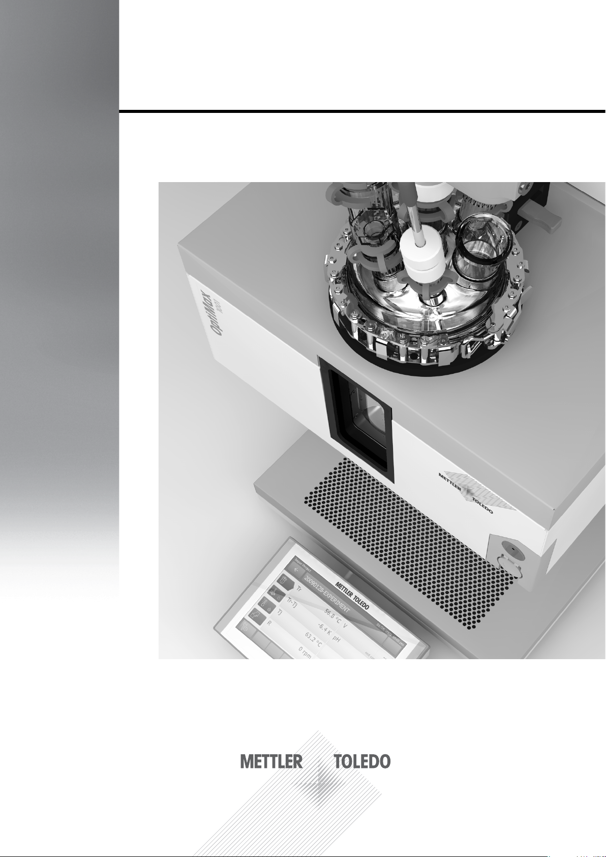
OptiMax™ 1001
Synthesis Workstation
Operating Instructions
Page 2

Page 3

Content
Content
1 Introduction .......................................................................................................... 6
2 Safety Measures ................................................................................................... 7
2.1 Measures for your protection ................................................................................. 7
2.2 Measures for Operational Safety ........................................................................... 8
3 Installation .......................................................................................................... 11
3.1 Location of the OptiMax™ 1001 .......................................................................... 11
3.2 Connections ......................................................................................................... 11
3.2.1 Connecting the Instrument, the Touchscreen and the Emergency Button ........... 13
3.2.2 The Relay for visual or acoustical signalization ................................................... 13
3.2.3 Connecting a Coolant ......................................................................................... 14
3.2.4 Connecting a Purge Gas ...................................................................................... 14
3.3 Installing the Overhead Stirrer ............................................................................. 16
3.4 Installing the 1000 mL Two-Piece Reactor .......................................................... 19
3.4.1 Openings of the 1000 mL Two-Piece Reactor Cover ........................................... 21
3.4.2 Installing a Tr Sensor in the ST 14 Opening ....................................................... 21
3.4.3 Installing Accessories ..........................................................................................22
3.4.4 The bottom drain valve of the Two-Piece Reactors ............................................. 23
3.5 Installing the 500 mL Two-Piece Reactor ............................................................. 25
3.5.1 Installing the Receptacle for the 500 mL Reactors ..............................................26
3.5.2 Openings of the 500 mL Two-Piece Reactor Cover ............................................. 26
3.6 Installing the 250 mL Two-Piece Reactor
3.6.1 Installing the Receptacle for the 250 mL Reactors ..............................................28
3.6.2 Openings of the 250 mL Two-Piece Reactor Cover ............................................. 28
3.7 Installing the 1000 mL One-Piece Reactor ..........................................................29
3.7.1 Installing the Overhead Stirrer ............................................................................. 29
3.7.2 Openings of the 1000 mL One-Piece Reactor ..................................................... 30
3.8 Installing the 500 mL One-Piece Reactor ............................................................31
3.8.1 Installing the Overhead Stirrer ............................................................................. 31
3.8.2 Openings of the 500 mL One-Piece Reactor ....................................................... 32
3.9 Installing the 250 mL One-Piece Reactor ............................................................33
3.9.1 Installing the Overhead Stirrer ............................................................................. 33
3.9.2 Openings of the 250 mL One-Piece Reactor ....................................................... 34
3.10 InstallingtheBafe ............................................................................................... 35
............................................................. 27
METTLER TOLEDO OptiMax
TM
1001 3
Page 4

Content
4 Design and Operating Principles ..................................................................... 36
4.1 Thermostat ........................................................................................................... 36
5 Temperature Control Modes ............................................................................. 37
5.1 Tj Mode ................................................................................................................ 37
5.2 Tr Mode ................................................................................................................ 37
5.3 Distillation Mode (Tj-Tr) ........................................................................................ 37
5.4 Crystallization Mode (Tr-Tj) .................................................................................. 38
6 Using additional instruments together with the OptiMax
1001 .................... 39
6.1 Dosing Unit DU SP-50 (ME-51161770) .............................................................. 39
7 Safety System of the OptiMax™ 1001 .............................................................. 40
7.1 Measures for Chemical Safety ............................................................................. 40
7.2 Measures for Intrinsic Safety ............................................................................... 40
7.3 Temperature Monitoring ....................................................................................... 41
7.4 Emergency Programs of the OptiMax™ 1001 ..................................................... 41
7.4.1 Emergency Program A ......................................................................................... 41
7.4.2 Emergency Program E ......................................................................................... 42
7.4.3 Warning "Tc < Tc min" .......................................................................................... 42
8 Maintenance and Servicing of the OptiMax
1001 .......................................... 43
8.2 Replacing the Valve Plug of the Bottom Drain Valve ........................................... 43
8.3 Changing the Coolant .......................................................................................... 43
8.4 Cleaning the Interior of the Thermostat ............................................................... 44
8.5 Cleaning the Instrument ....................................................................................... 44
8.6 Disposing of the Instrument ................................................................................. 45
9 Malfunctions of the OptiMax™ 1001 ................................................................ 46
9.1 Instrument ............................................................................................................ 46
9.2 Stirrer ................................................................................................................... 46
9.3 Heating ................................................................................................................. 46
10 Technical data .................................................................................................... 47
10.1 Thermostat ........................................................................................................... 49
10.2 Reactors ............................................................................................................... 50
10.3 Stirrer ................................................................................................................... 50
10.4 Cooling ................................................................................................................. 50
4 METTLER TOLEDO OptiMax
TM
1001
Page 5

Content
METTLER TOLEDO OptiMax
TM
1001 5
Page 6

Introduction
1 Introduction
The METTLER TOLEDO OptiMaxTM 1001 is a reactor system for performing synthesis with a 250-mL,
a 500-mL, or a 1000-mL glass reactor. The instrument is operated via the integrated touchscreen.
• The reactor can be heated or cooled and its content stirred and reuxed.
• The temperature of the reactor content can be measured using a Pt100 sensor.
• The integrated pH measurement system equipped with the appropriate electrode allows you to
measure the pH value of the reactor content.
• You can export the acquired data to another program for further processing using the USB Memory
Stick supplied.
We, Mettler-Toledo AG, accept no liability whatsoever if you do not observe the following rules
and measures for safe operation of the OptiMax™ 1001 with the glass reactor!
6 METTLER TOLEDO OptiMax
TM
1001
Page 7
Safety Measures
2 Safety Measures
The OptiMax™ 1001 has been tested for the experiments and intended purposes documented in
these Operating Instructions. However, this does not absolve you from the responsibility of performing your own tests of the product supplied by us regarding its suitability for the methods and purposes
you intend to use it for. You should therefore observe the following safety measures.
Please comply with all safety and accident-prevention regulations, as in force for
laboratory work!
2.1 Measures for your protection
Grounding of the power supply outlet
– Make sure you plug the power cable supplied into a power supply outlet that is
grounded! A technical fault could otherwise result in death or serious injury.
Risk of an elec-
trical shock
Risk of explosion
Risk of explosion
Risk of explosion
Risk of explosion
Power failure
– Implement appropriate measures like an uninterruptible power systems (UPS)
against possibly fatal consequences of a power failure!
Potentially explosive environment
– Never work in an environment subject to explosion hazards! The OptiMax
TM
1001 housing is not gas tight (explosion hazard due to spark formation, corrosion caused by ingress of gases).
Critical reactions
– Always perform a safety analysis before starting investigations with a high haz-
ard potential, for example by a Differential Scanning Calorimeter!
Electrostatic charge formation through stirring of the reaction mass
Hazardous charges can build up in the reactor interior under the following conditions:
• when nonpolar liquids of high resistivity (>10
8
Ω.m) are stirred at high speed (i.e.
at high ow rates),
• with two-phase systems with suspended solids (e.g. after crystallization pro-
cesses in nonconductive solvents or immiscible liquids).
– We therefore recommend to work under an inert atmosphere (nitrogen or ar-
gon)!
METTLER TOLEDO OptiMax™ 1001 7
Page 8
Safety Measures
Risk of explosion
Risk of burns
Hand injury
Reactors
– Check the reactor periodically for damage (scratches, formation of cracks)!
Hot parts
– Do not touch the cover plate of the box, the xing ring, reactor cover and attach-
ments of the reactors or the overhead stirrer if you work at temperatures above
50 °C.
– The housing of the stirring motor may become hot.
Overhead stirrer
– Do not hold the rotation stirrer shaft or the coupling by hand when you operate
the stirrer motor! You could injure your ngers.
2.2 Measures for Operational Safety
Connection of cables
– Connect the cables of stirrers or sensors to their respective inputs and outputs
before you switch on the instrument, and do not disconnect a cable while the
system is in operation! The printed circuit board of the instrument could other-
Caution
Caution
Caution
wise be damaged.
– Make sure that the power supply is easily accessible at any time.
Ventilation of the instrument
– Make sure the instrument is well ventilated! It dissipates a lot of heat especially
during longer heating periods and if the temperature difference between the
temperature of the thermostat (Tj) and the temperature of the coolant (Tc) is
large. If the temperature of the instrument is too high, its temperature protection
device is activated, i.e. the instrument is switched off. After cooling down, you
can switch it on again.
– Leave a free space of at least 10 cm between the ventilation slots at the back
side of the instrument and any other object or the wall.
Condensation of atmospheric moisture
– Purge the instrument with dry air, nitrogen or argon (3 L/min without purging the
reactor)! This prevents the ingress and condensation of atmospheric moisture
and therefore possible corrosion of the instrument.
8 METTLER TOLEDO OptiMax™ 1001
Page 9
Caution
Safety Measures
Cooling
The instrument needs a constant ow of a cooling medium. You can use salt-free
tap water, ethanol, ethylen glycol or silicone oil.
– If the water is polluted or has a high degree of hardness, install a lter in the
inlet line and clean it regularly!
– Do not use the owmeter with any other liquids than water, the owmeter is not
resistant against other liquids than water!
Cooling with cryostats
– Do not use NaCl or CaCl
solutions! The high chloride concentration can lead
2
to corrosion of the heat transfer area of the instrument.
– Do not use the owmeter with any other liquids than water, the owmeter is
not resistant against other liquids than water! Connect any other cooling liquid
directly to "Cooling In" without using the owmeter!
Thermal shock
Avoid any thermal shock in conjunction with the glass parts of the instrument.
– Never ll cool liquids into hot glassware and vice versa.
Caution
Caution
Caution
Caution
Service
– Never open the instrument! Have it serviced only by METTLER TOLEDO ser-
vice.
General
– Exclude the following environmental inuences
• powerful vibrations,
• direct sunlight,
• atmospheric humidity greater than 80%,
• temperatures below 5 °C and above 40 °C,
• powerful electric or magnetic eld!
METTLER TOLEDO equipment, accessories, and spare parts
– Only use original METTLER TOLEDO equipment, accessories, and spare
parts in conjunction with the OptiMax™ 1001 - otherwise the instrument or
parts of the instrument may get damaged. This especially applies for the reactor, its cover, the stirrer and the stirrer shaft.
METTLER TOLEDO OptiMax™ 1001 9
Page 10

Safety Measures
Caution
Touchscreeen connection
Do not connect/disconnect the touchscreen while the OptiMax™ is switched on.
This may seriously damage the instrument.
10 METTLER TOLEDO OptiMax™ 1001
Page 11
Installation
3 Installation
3.1 Location of the OptiMax™ 1001
– Set up the instrument in a fume hood according to the general safety requirements.
– Variations in chemical behavior during handling due to factors such as temperature,
pressure and concentration can cause equipment to fail, even though it passed an
Caution
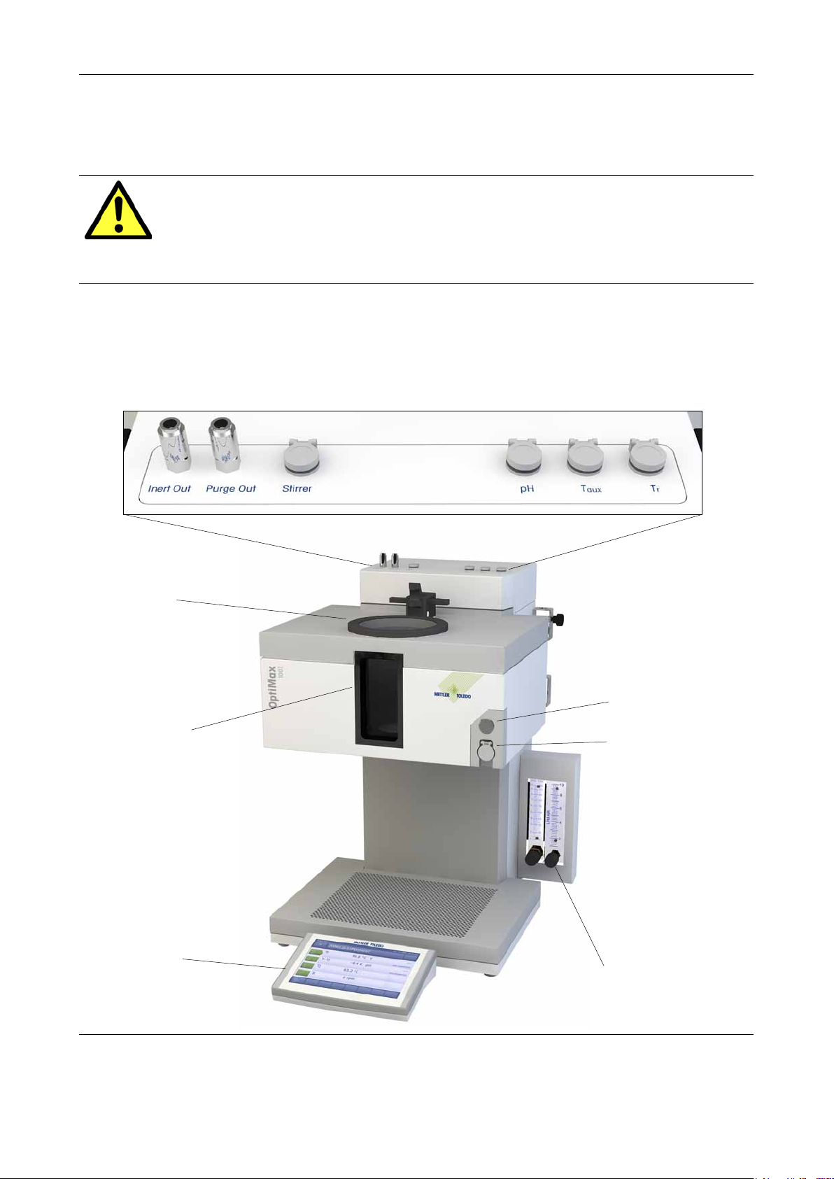
3.2 Connections
On top of the housing you nd the quick connect couplings for the purge and inert gas outlets and the
sockets for the overhead stirrer, the Tr sensor, a pH sensor and an additional temperature sensor (T
Front view:
initial test. SERIOUS INJURY MAY RESULT. Use suitable guards and/or personal protection when handling chemicals.
aux
):
Opening of thermostat
Reactor window
(with back- and
frontlight)
Touchscreen with
color display
Power push button
Socket for USB stick
Flow indicators for
control of purge gas and
cooling water
METTLER TOLEDO OptiMax™ 1001 11
Page 12

Installation
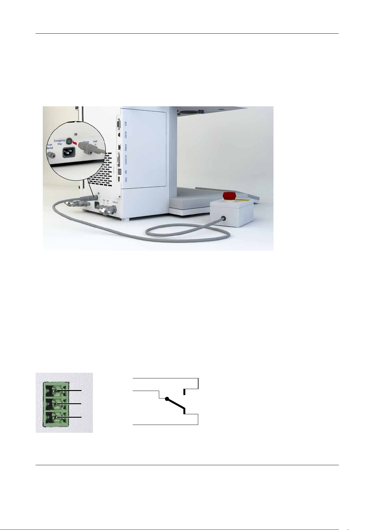
Rear view
On the right rear side of the instrument you can nd the RS232 interface, the CAN bus (for additional
equipment), the network connection, the connector for the touchscreen (Control Unit), two USB con-
nectors and the connector for the emergency relay:
Holder for lab bars
The power supply, the elbow couplings for the coolant in- and outlet, the quick connect couplings
for the purge- and inert gas inlets and the connector for the internal purging can be found on the
rear bottom of the instrument. The connector for the emergency stop button is also situated in this
place.
12 METTLER TOLEDO OptiMax™ 1001
Page 13
Installation
3.2.1 Connecting the Instrument, the Touchscreen and the Emergency Button
– Connect the touchscreen to the instrument. (See chapter 3.2 "Connections")
– Connect the emergency button to the "Emergency Stop" connector on the rear bottom of the instru-
ment. (See chapter 3.2 "Connections")
– Connect the instrument to the power supply using the included country-specic cable.
The emergency button will trigger the emergency program E when pressed. (See chapter 8.4.2 "Emergency
Program E")
Note
The emergency button is only active during an active ramp! As long as no ramp is running, pressing
the emergency button will have no effect on the system!
3.2.2 The Relay for visual or acoustical signalization
The emergency relay is thought for connecting an optical or visual alarm. In case no emergency
program is triggered, pins 1 and 2 are connected. As soon as an emergency program is triggered,
the relay switches and pins 2 and 3 are connected.
Relay switched off: contact
between pin 1 and pin 2
Relay switched on: contact
between pin 2 and pin 3
(Meaning an emergency pro-
gram has been triggered.)
3
2
1
3
2
1
Contact load: 30 V / 3 A for ohmic and inductive load
METTLER TOLEDO OptiMax™ 1001 13
Page 14

Installation
3.2.3 Connecting a Coolant
The instrument requires a constant ow of a cooling medium (see Section 2.2: "Measures for Operational Safety: Cooling" and Chapter 10: "Technical Data").
1. Connection of a coolant
– Push one piece of the fabric tube (No. 51 161 187, ø 8/14 mm) over the cooling inlet of the
coolant owmeter, secure it with a hose clamp, and connect it to the coolant supply.
– Push a second piece of the PVC tube over the elbow coupling of the cooling outlet on the
back side of the instrument, secure it with a hose clamp and connect it to the waste water
system.
Note:
Never use the ow indicator for the coolant nor the coolant owmeter for any other liquids than
water!
2. Connection of a cryostat
– Screw the insulated connection tubes directly onto the inlet/outlet connectors on the back
side of the instrument.
Caution:
Never use the owmeter for the coolant when using a cryostat, the owmeter is not resistant
against other liquids than water!
3.2.4 Connecting a Purge Gas
Caution Operation without purging the instrument can damage the instrument and will void
the warranty!
To prevent corrosion by condensed atmospheric moisture in the instrument, the instrument must be
purged with a dry gas, e.g. dried air, dried nitrogen or dried argon (see Chapter 11: Technical data).
– Install a PVC tube (No. 51 192 239, ø 4/10 mm ) on the purge gas inlet of the purge gas owmeter,
secure it with a hose clamp and connect it to the gas supply.
Note:
The "Purge In" and "Inert In" inlets on the back side of the instrument are directly connected to
the outlets on top of the housing via seperate lines and are thought for purging the stirrer housing
(Purge Out) or to feed the reactor with inert gas (Inert Out).
14 METTLER TOLEDO OptiMax™ 1001
Page 15
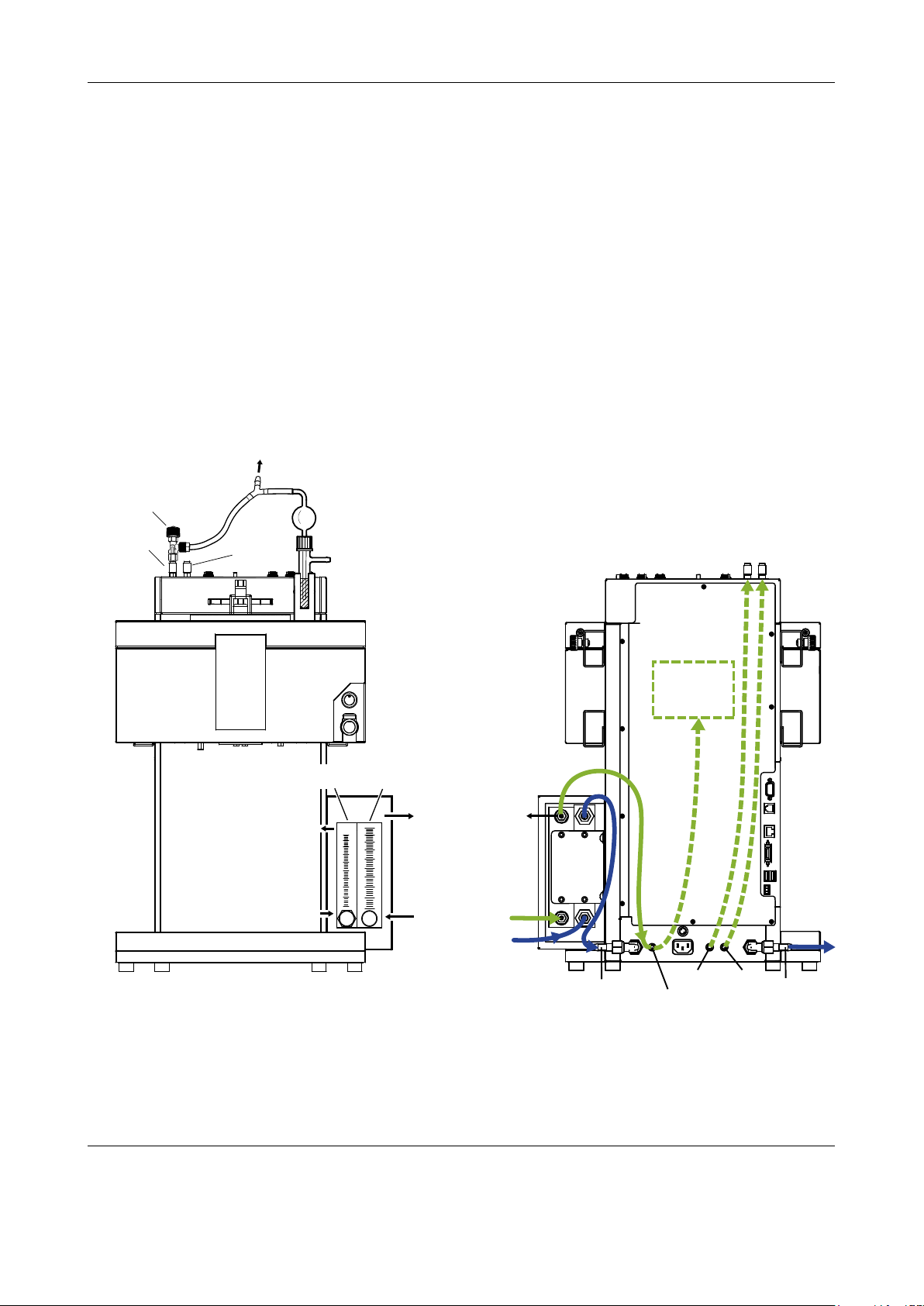
Installation
Inert gas for
reactor
Gas regulation valve
Inert Out
2
6
4
8
10
1
3
5
7
9
600
540
480
420
360
300
60
240
180
120
LPM
LPH
2
6
4
8
10
LPM AIR
From coolant
supply
Cooling Out
(to “Cooling In”
on the back side
of the OptiMax)
Purge gas
flowmeter
Coolant
flowmeter
Purge gas In
Purge gas Out
(to “Purge Internal”
on the back side of
the OptiMax)
Purge Out
(to stirrer
Purge In)
Coolant In
Purge Internal
Purging the reactor with inert gas
If you want to perform reactions under nitrogen (or any other inert gas),
– Install a quick connect coupling (No. 51 190 324, ø 4/6 mm, red) with the PVC tube (No. 51 161
186) on the "Inert In" inlet connector on the back side of the instrument and secure it with a hose
clamp.
– Connect the PVC tube to the gas supply.
– Install a quick connect coupling on the "Inert Out" connector on top of the instrument and push a
piece of the PVC tube (No. 51 161 186) over the quick connect coupling.
– Integrate a bubble counter with a gas regulation valve (51 161 802, optional available as set) and
the wye piece (51 191 373) into the tubing as shown in the drawing. Proceed, depending on the
type of the used reactor. (The use of the wye piece guarantees an uncritical pressure for the reactor while the gas ow can be monitored with the bubble counter.)
– Always leave a small opening in the reactor to allow a ow of the puge gas.
green line: purge- / inert gas
blue line: coolant
dashed line: tubing inside of the instrument
Internal
purging of the
Instrument
Cooling In
METTLER TOLEDO OptiMax™ 1001 15
Purge In
Inert In
Cooling Out
Page 16
Installation
With the 500 mL/ 1000 mL reactor
– Use the glass adapter ST19/26 GL14,
– First slide the end of the PVC tube (a) through the screw cap (ME 51 190 317, b),
– then through the silicone rubber sealing ring (ME 51 103 947, c),
– and nally screw the cap onto an ST 19/26 GL14 glass adapter (ME 51 192 208, d).
c abd
– Place the adapter in an ST 19 ground glass opening.
3.3 Installing the Overhead Stirrer
The overhead stirrer consists of
• the stirrer motor with already mounted chuck and clamping nut for fastening the stirrer shaft,
• a Alloy 22 stirrer shaft with pitched-blade stirrer elements in Alloy 22 for two-piece reactors or
• a borosilicate glass stirrer shaft with a PTFE half-moon stirrer blade for one-piece reactors,
• a PTFE adapter with sealing sleeve, compession spring and adapter loosening device,
(the loosening device is already mounted on the adapter)
• the locking device which secures the stirrer shaft.
PTFE Sealing rings
In case the stirrer adapter gets
stuck on the reactor cover, turn the
loosening ring counterclockwise
until it pushes slightly against the
ground joint. While carefully turning it further, the stirrer adapter
wil come loose and can be taken
away.
Note:
In case you are using PTFE sealing rings between stirrer adapter
and ground joint, make sure you
always use two of them on different heights of the adapter to avoid
tumbling of the stirrer!
16 METTLER TOLEDO OptiMax™ 1001
Page 17

Locking device
Chuck
Clamping nut
Stirrer adapter
Adapter loosening device
Stirrer shaft
Pitched-blade element
Compression spring
Bearing sleeve
Purge gas
inlet (optional)
Installation
Assembling the stirrer
– Screw the pitched-blade element onto the stirrer
shaft.
– Push the stirrer shaft from below through the
opening of the reactor cover.
– Push the adapter loosening device over the stirrer
shaft.
– Push the stirrer adapter with the bearing sleeve
and the compression spring over the stirrer shaft
and screw the loosening device bottom-up onto
the adapter.
– Fasten the adapter with the bayonet coupling to
the stirrer motor.
– Push the stirrer shaft through the stirrer motor.
– Carefully check and adapt the height of the stirrer
shaft and the pitched-blade element with the reactor for an applicable immersion depth.
– Fix the stirrer shaft by tightening the chuck. and
secure it with the locking device on top of the
chuck.
(The locking device prevents the stirrer shaft from
falling into the reactor in case the chuck is loosened uncarefully or by mistake.)
– Insert the adapter into the central opening of the
cover.
– Connect the stirrer cable to the connector on top
of the instrument housing.
To change the immersion depth of the stirrer shaft :
– Release the chuck while holding the stirrer shaft.
– Release the locking device and adapt the immer-
sion depth.
– Tighten the chuck and secure it with the locking
device.
Caution
Always check the stirrer for being mounted properly and not touching any sensors or other inserts
before you let it run! The bearing sleeve has to contact the stirrer shaft tight-tting.
In case you encounter problems with a worn out bearing sleeve (as a result the stirrer shaft may
no longer be tight) please replace the bearing sleeve (ME 51192163). An additional bearing sleeve
should always be kept in stock for replacement.
METTLER TOLEDO OptiMax™ 1001 17
Page 18

Installation
A
B
A
B
x
B
A
Caution
Make sure the compression spring is correctly inserted on the bearing sleeve.
While assembling the stirrer motor of OptiMax™, make sure that the nose of the bearing sleeve (A)
ts perfectly in the notch of the stirrer adapter (B).
Do not force (A) into (B) when nose and notch do not t!
Caution
Make sure the purge gas inlet is not completely screwed into the stirrer housing. The whole purge
gas inlet should stick out at least 2.5 cm in order to allow correct functioning of the stirrer.
2.5 cm
18 METTLER TOLEDO OptiMax™ 1001
Page 19

Installation
3.4 Installing the 1000 mL Two-Piece Reactor
– Push the glass stirrer or the stirrer shaft with anchor or pitched-blade element through the central
opening of the reactor cover before you place the cover onto the reactor and connect it to the stirrer
motor (see Section 3.3: Installing the Overhead Stirrer).
Reactor cover
ME 51 162 671
Clamp chain
ME 51 162 673
O-ring
O-ring
ME 51 192 205
Hook
Buckle
Fastening for
lab bar
1000 mL reactor
ME 51 162 634
Reactor holder
(1000 mL)
ME 51 162 782
– Fix the reactor holder (ME 51 162 782) to
one of the lab bars and place the reactor in
the reactor holder.
– Place the O-ring on the cover rim and
place the cover on the reactor.
– Place the clamp chain carefully around the
cover and the reactor anges.
– Screw the hook in or out so that the
buckle can be easily closed (with one
nger).
Note
Before you place the reactor in the thermostat, we recommend that you install the Tr
sensor and other inserts in order to check
their distance from the stirrer or the bottom
of the reactor. We also recommend that you
add the reagents and solvent for the starting
volume and possibly check the ll level of the
rst ll. The Tr sensor must be immersed in
the reaction solution to a depth of at least 1.5
cm for glass sensors or 2.5 cm for sensors
made of Alloy 22 to give correct measure-
ment values.
METTLER TOLEDO OptiMax™ 1001 19
Page 20

Installation
– Remove the assembled reactor from the
reactor holder and insert it into the thermostat.
– Attach the drain union (ME 51 162 685) to
the bottom drain valve and fasten it with the
pinch clamp.
Caution:
Always remove the pinch clamp and the drain
union before removing the reactor from the
thermostat!
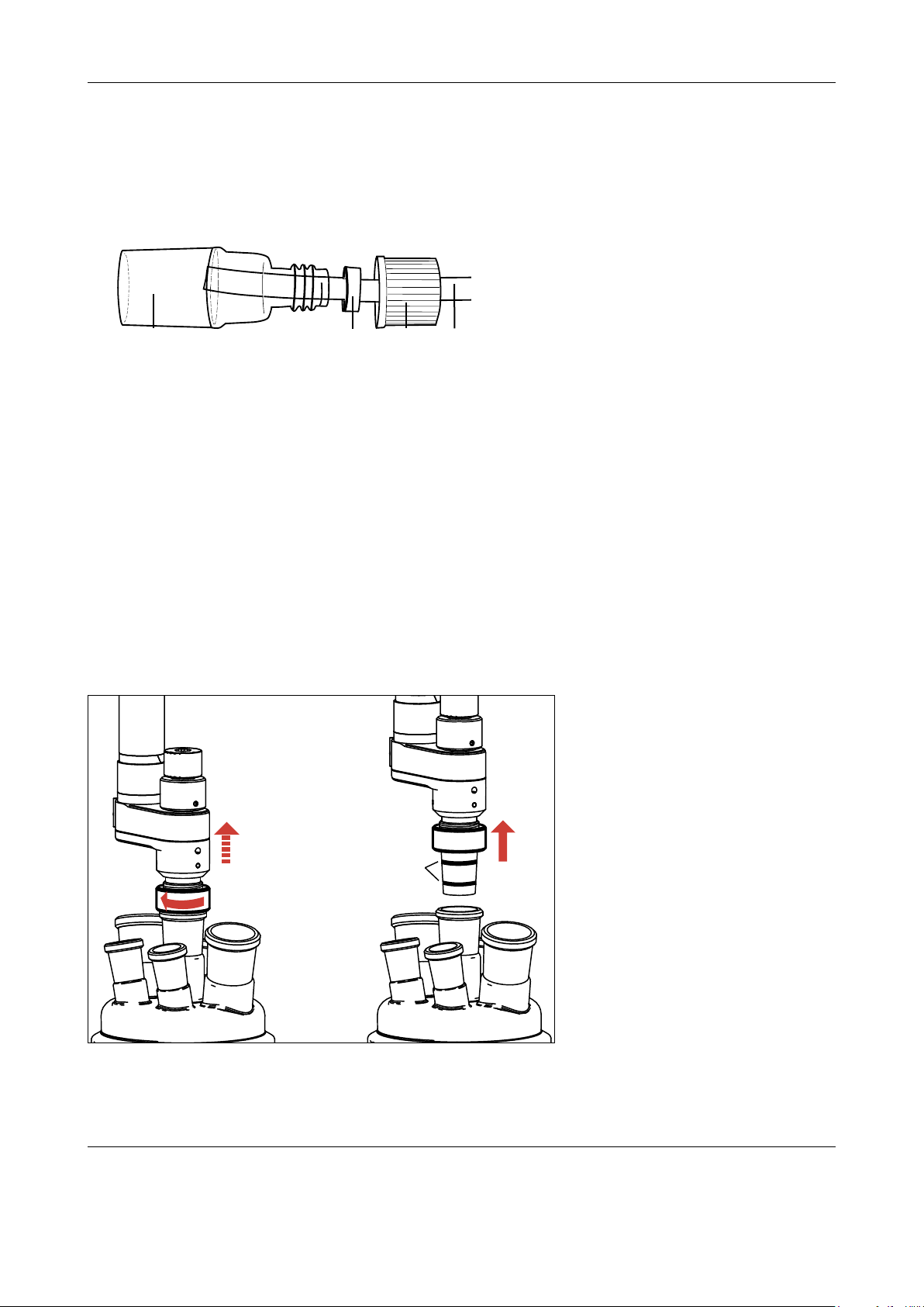
The rotation lock
After you insert the reactor into the thermostat you should always lock it using the rotation lock - this
prevents the reactor from rotating concurrently while you open or close the bottom drain valve.
Push the blue rotation lock towards the reactor. Make sure the lower pin ts into the chain and holds
it in place. (See the left picture below.)
The rotation device can also be used to lock the reactor in an uplift position. Uplift the reactor and
lock it with the upper pin of the rotation lock. In this uplift position the bottom of the reactor can be
observed through the reactor window. (See the right picture below.)
20 METTLER TOLEDO OptiMax™ 1001
Page 21

Installation
3.4.1 Openings of the 1000 mL Two-Piece Reactor Cover
Choose the openings for inserts and attachments so that cable and tubing connections are as neat
and tidy as possible.
ST19/26
ST19/26
ST24/29
Overhead stirrer
ST29/32
ST29/32
ST14/23
Tr sensor
ST19/26
3.4.2 Installing a Tr Sensor in the ST 14 Opening
– Use the eccentric PTFE adapter (No. 51 162 720) with an inner diameter of 6 mm
– First unscrew the screw (No. 51 162 715, b) from the adapter and push it over the sensor (a ),
– next push the sealing ring (No. 51 162 716, c) over the Tr sensor with the round side pointing to
the screw,
– and nally the lower part of the adapter (No. 51 162 721, d).
abcd
– Screw the adapter lightly together: this compresses the sealing ring and tightens the Tr sensor in
the adapter.
Always handle Tr sensors made of glass with special care and do not apply
any force - otherwise the glass may break and cause injury!
Caution
METTLER TOLEDO OptiMax™ 1001 21
Page 22

Installation
3.4.3 Installing Accessories
1. The central ground glass opening of the reactor cover (ST24/29) is reserved for the overhead
stirrer.
2. The ST14/23 is intended for the Tr sensor. (See chapter 3.4.2).
3. When using the OptiMax pH electrode with ø 12 mm in an ST 19 opening,
– unscrew the nut of the ST 19/26 guide sleeve slightly and push the electrode through the
adapter (No. 51 162 717).
– Place the sleeve on the corresponding opening, set the desired distance to the stirrer and
tighten the nut.
– Connect the cable of the pH electrode to the instrument.
When using sensors with 6-mm diameter in an ST 14 opening,
– unscrew the nut of the ST 14/23 guide sleeve slightly and push the sensor through the adapter
(No. 51 162 720).
– Place the sleeve on the corresponding opening, set the desired distance to the stirrer and
tighten the nut.
– Connect the cable of the sensor to the instrument.
4. When using the reux condenser
– push the two plastic hose connections with seal (No. 51 190 319) each through the hole of a
GL 14 screw cap (No. 51 190 317), push a tube over each hose connection and secure it with
a hose clamp.
– Tighten the plastic hose connections with the screw cap on the two glass threads of the reux
condensor.
– When you have installed sensors and accessories, place the reactor in the thermostat.
– If you have installed the overhead stirrer and Tr sensor, connect their cables to the connectors on
top of the instrument.
Note
When the experiment is completed, you can remove the cover with the inserts from the reactor, rinse
22 METTLER TOLEDO OptiMax™ 1001
Page 23

the inserts and place the cover on the reactor holder xed on a lab bar:
Installation
3.4.4 The bottom drain valve of the Two-Piece Reactors
The assembly of the bottom drain valve (which is used for the 500 mL and 1000 mL two-piece reactors) can be derived from the drawing on the next page.
The drain valve is delivered already assembled. To open or close the valve simply turn the spindle in
a way that its blue tip opens or seals the drain at the bottom of the reactor.
Caution
The spindle has a strong spring integrated, which compensates expansion and contraction of the re-
actor materials caused by variations in temperature. At the same time it ensures a proper sealing of
the drain. To retain the function of this spring and to avoid breaking of the reactor glass always close
the bottom drain valve hand-tight and afterwards reopen it slightly (quarter to half a turn).
To disassemble the valve for cleaning proceed as follows:
1 Unscrew the spindle and pull it slightly back.
2 Loosen the pressure screw slightly and remove the spindle from the valve.
3 Loosen the pressure screw completely and put it aside.
4 Remove the pressure piece and the sealing ring.
5 After removing the insert ring, at last the connecting nut can be taken away.
METTLER TOLEDO OptiMax™ 1001 23
Page 24

Installation
Reactor
Connecting nut
Insert ring
Sealing ring
Pressure piece
Pressure screw
Spindle
ME 51 162 724
ME 51 162 727
ME 71 540
ME 51 162 726
ME 51 162 725
ME 51 191 774
In case the valve cannot be disassembled easily due to contamination from the
outside, try to rinse it from the outside with a suitable solvent. Never use force while
trying to disassemble the valve!
Caution
The reassembly of the bottom drain valve can be learned from the following picture:
1 Slide the pressure screw over the spindle.
2 Slide the pressure piece over the spindle.
3 Slide the sealing ring over the spindle.
4 Slide the connecting nut over the valve joint of the reactor and x it with the insert ring.
(Make sure the insert ring is inserted properly!)
5 Insert the premounted spindle into the reactor and screw the pressure screw into the
connecting nut (hand-tight).
6 Screw the spindle into the pressure piece.
24 METTLER TOLEDO OptiMax™ 1001
Page 25

Installation
3.5 Installing the 500 mL Two-Piece Reactor
The 500 mL two-piece reactor comes with the same reactor cover as the 1000 mL two-piece reactor.
Since the reactor itself is smaller than the 1000 mL reactor, you have to use a receptacle
(ME 51 162 670) for tting it into the thermostate (See chapter 3.5.1). In addition you need to use the
smaller reactor holder for the 500 mL reactor (ME 51 162 783):
– Push the glass stirrer or the stirrer shaft with anchor or pitched-blade element through the central
opening of the reactor cover before you place the cover onto the reactor and connect it to the stirrer
motor (see Section 3.3: Installing the Overhead Stirrer).
Reactor cover
ME 51 162 671
Clamp chain
ME 51 162 673
O-ring
ME 51 192 205
Fastening for
lab bar
Hook
500 mL reactor
ME 51 162 632
Reactor holder
(500 mL)
ME 51 162 783
Buckle
– Fix the reactor holder (ME 51 162 783) to
one of the lab bars and place the reactor in
the reactor holder.
– Place the O-ring on the cover rim and place
the cover on the reactor.
– Place the clamp chain carefully around the
cover and the reactor anges.
– Screw the hook in or out so that the buck-
le can be easily closed (with one nger).
Note
The assembly of the bottom drain valve is ex-
plained in chapter 3.4.4.
METTLER TOLEDO OptiMax™ 1001 25
Page 26

Installation
Receptacle (500 mL)
ME 51 162 670
Locking Pin
Note
Before you place the reactor in the thermostat, we recommend that you install the Tr sensor and
other inserts in order to check their distance from the stirrer or the bottom of the reactor. We also
recommend that you add the reagents and solvent for the starting volume and possibly check the ll
level of the rst ll. The Tr sensor must be immersed in the reaction solution to a depth of at least 1.5
cm for glass sensors or 2.5 cm for sensors made of Alloy 22 to give correct measurement values.
3.5.1 Installing the Receptacle for the 500 mL Reactors
– Insert the receptacle into the thermo-
stat with the window heading forward.
Make sure the locking pin on the side
snaps into place.
3.5.2 Openings of the 500 mL Two-Piece Reactor Cover
The openings of the 500 mL two-piece reactor are the same like the openings of the 1000 ml twopiece reactor. (See chapter 3.4.1)
– Remove the assembled reactor from the
reactor holder and insert it into the thermostat.
– Attach the drain union (ME 51 162 685) to
the bottom drain valve and fasten it with the
pinch clamp.
Caution:
Always remove the pinch clamp and the drain
union before removing the reactor from the
thermostat!
26 METTLER TOLEDO OptiMax™ 1001
Page 27

Installation
3.6 Installing the 250 mL Two-Piece Reactor
Since the reactor itself is smaller than the 1000 mL reactor, you have to use a receptacle
(ME 51 162 698) for tting it into the thermostate (See chapter 3.5.1). In addition you need to use
the smaller reactor stand for the 250 mL reactor (ME 51 162 758):
– Push the glass stirrer or the stirrer shaft with anchor or pitched-blade element through the central
opening of the reactor cover before you place the cover onto the reactor and connect it to the stirrer
motor (see Section 3.3: Installing the Overhead Stirrer).
– Place the reactor in the reactor stand.
Reactor cover
ME 51 162 699
– Place the O-ring on the cover rim and place
the cover on the reactor.
– Place the clamp chain carefully around the
Clamp chain
ME 51 162 703
cover and the reactor anges.
– Screw the hook in or out so that the buckle
can be easily closed (with one nger).
O-ring
ME 51 192 170
Hook
250 mL reactor
ME 51 162 635
Reactor stand
(250 mL)
ME 51 162 758
Buckle
Note
Before you place the reactor in the thermostat,
we recommend that you install the Tr sensor and
other inserts in order to check their distance from
the stirrer or the bottom of the reactor. We also
recommend that you add the reagents and sol-
vent for the starting volume and possibly check
the ll level of the rst ll. The Tr sensor must be
immersed in the reaction solution to a depth of
at least 1.5 cm for glass sensors or 2.5 cm for
sensors made of Alloy 22 to give correct mea-
surement values.
METTLER TOLEDO OptiMax™ 1001 27
Page 28

Installation
Receptacle (250 mL)
ME 51 162 698
Locking Pin
3.6.1 Installing the Receptacle for the 250 mL Reactors
– Insert the receptacle into the thermostat
with the window heading forward. Make
sure the locking pin on the side snaps into
place.
– Remove the assembled reactor from the
reactor stand and insert it into the thermostat.
3.6.2 Openings of the 250 mL Two-Piece Reactor Cover
ST19/26
ST14/23
ST24/29
Overhead stirrer
ST19/26
ST19/26
ST19/26
ST14/23
28 METTLER TOLEDO OptiMax™ 1001
Page 29

3.7 Installing the 1000 mL One-Piece Reactor
Like the 1000 mL two-piece reactor, the 1000 mL
one-piece reactor is used without a receptacle.
Instead of the reactor holder, the reactor stand
(ME 51 162 760) is used to store and prepare the
reactor.
Installation
1000 mL reactor
ME 51 162 732
Reactor stand
(1000 mL)
ME 51 162 760
The lling is done via the openings for inserts and
attachements. If not in use, or preparing for use,
the reactors can be stored in the reactor stand.
Note
Before you place the reactor in the thermostat, we
recommend that you install the Tr sensor and other
inserts in order to check their distance from the stirrer or the bottom of the reactor. We also recommend that you add the reagents and solvent for the
starting volume and possibly check the ll level of
the rst ll. The Tr sensor must be immersed in the
reaction solution to a depth of at least 1.5 cm for
glass sensors or 2.5 cm for sensors made of Alloy
22 to give correct measurement values.
– Insert the plug (ME 51 162 860 with
sealing ME 51 192 209) from below
into the lower opening of the thermo-
stat. (This will eliminate any disturbing
stack-effect from the thermostat.)
3.7.1 Installing the Overhead Stirrer
– Push the stirrer through the central opening of the reactor. Only use the glass stirrer (ME-51 162 681)
and the corresponding stirrer blade (ME- 51 162 682) in connection with the 1000 mL one-piece
reactor!
METTLER TOLEDO OptiMax™ 1001 29
Page 30

Installation
3.7.2 Openings of the 1000 mL One-Piece Reactor
Choose the openings for inserts and attachments so that cable and tubing connections are as neat
and tidy as possible.
ST19/26
ST19/26
ST24/29
Overhead stirrer
ST19/26
ST19/26
ST29/32
ST14/23
30 METTLER TOLEDO OptiMax™ 1001
Page 31

3.8 Installing the 500 mL One-Piece Reactor
500 mL reactor
ME 51 162 733
Reactor stand
(500 mL)
ME 51 162 759
Installation
Like the 500 mL two-piece reactor, the
500 mL one-piece reactor is used with a
receptacle. (See chapter 3.5.1)
Instead of the reactor holder, the reactor
stand (ME 51 162 759) is used to store
and prepare the reactor.
The lling is done via the openings for
inserts and attachements. If not in use,
or preparing for use, the reactor can be
stored in the reactor stand.
Note
Before you place the reactor in the thermostat, we recommend that you install
the Tr sensor and other inserts in order to
check their distance from the stirrer or the
bottom of the reactor. We also recommend
that you add the reagents and solvent for
the starting volume and possibly check the
ll level of the rst ll. The Tr sensor must
be immersed in the reaction solution to a
depth of at least 1.5 cm for glass sensors
or 2.5 cm for sensors made of Alloy 22 to
give correct measurement values.
- Insert the plug (ME 51 162 860 with
sealing ME 51 192 209) from below
into the lower opening of the thermo-
stat. (This will eliminate any disturbing
stack-effect from the thermostat.)
3.8.1 Installing the Overhead Stirrer
– Push the stirrer through the central opening of the reactor. Only use the glass stirrer (ME-51 161 681)
and the corresponding stirrer blade (ME- 51 161 682) in connection with the 500 mL one-piece
reactor!
METTLER TOLEDO OptiMax™ 1001 31
Page 32

Installation
3.8.2 Openings of the 500 mL One-Piece Reactor
Choose the openings for inserts and attachments so that cable and tubing connections are as neat
and tidy as possible.
ST19/26
ST19/26
ST24/29
Overhead stirrer
ST19/26
ST19/26
ST14/23
ST14/23
32 METTLER TOLEDO OptiMax™ 1001
Page 33

3.9 Installing the 250 mL One-Piece Reactor
250 mL reactor
ME 51 162 734
Reactor stand
(250 mL)
ME 51 162 758
Installation
Like the 250 mL two-piece reactor, the
250 mL one-piece reactor is used with a
receptacle. (See chapter 3.5.1)
The reactor stand (ME 51 162 758) is
used to store and prepare the reactor.
The lling is done via the openings for
inserts and attachements. If not in use,
or preparing for use, the reactor can be
stored in the reactor stand.
Note
Before you place the reactor in the thermostat, we recommend that you install
the Tr sensor and other inserts in order to
check their distance from the stirrer or the
bottom of the reactor. We also recommend
that you add the reagents and solvent for
the starting volume and possibly check the
ll level of the rst ll. The Tr sensor must
be immersed in the reaction solution to a
depth of at least 1.5 cm for glass sensors
or 2.5 cm for sensors made of Alloy 22 to
give correct measurement values.
- Insert the plug (ME 51 162 860 with
sealing ME 51 192 209) from below
into the lower opening of the thermo-
stat. (This will eliminate any disturbing
stack-effect from the thermostat.)
3.9.1 Installing the Overhead Stirrer
– Push the stirrer through the central opening of the reactor. Only use the glass stirrer (ME-51 161 681)
and the corresponding stirrer blade (ME- 51 161 684) in connection with the 250 mL one-piece
reactor!
METTLER TOLEDO OptiMax™ 1001 33
Page 34

Installation
3.9.2 Openings of the 250 mL One-Piece Reactor
Choose the openings for inserts and attachments so that cable and tubing connections are as neat
and tidy as possible.
ST14/23
ST19/26
ST24/29
Overhead stirrer
ST19/26
ST19/26
ST14/23
ST19/26
34 METTLER TOLEDO OptiMax™ 1001
Page 35

Installation
3.10 Installing the Bafe
The bafe is inserted in one of the ST 19 openings of the reactor. Using the eccentric PTFE adapter
(ME 51 104 154) and due to the fact that the bafe itself is angular, it can be t in the reactor in a way
that it does not collide with the stirrer, the Tr sensor or any other insert of the reactor.
For each reactor size a matching bafe is offered:
Adapter for bae
(eccentric)
ME 51 104 154
Bae
500 mL ME 51 162 638
1000 mL ME 51 162 637
Bafe
METTLER TOLEDO OptiMax™ 1001 35
Page 36

Design and Operating Principles
4 Design and Operating Principles
The OptiMaxTM 1001 comprises four modules:
• Electronic control unit
• Thermostat
• Measurement system
• Touchscreen
The Touchscreen is used to control the OptiMax™ 1001, to perform experiments and manage the
related data (store and export experimental data). See document number
Operating Instructions
for detailed information.
The microprocessor control in the instrument acquires a set of the set and actual values every 2
seconds: the temperature of the reaction mass, thermostat, and coolant as well as the stirrer speed,
, and pH.
T
aux
These values are used for controlling the instrument and to trigger warnings and emergency programs.
30032003- Touchscreen
4.1 Thermostat
Tr Sensor
Reactor Wall
Tc Sensor
Heater
Reactor shell
Overhead Stirrer
Peltier Element
Tj Sensor
Heater
Cooling element
• The Tr sensor measures the temperature of the reactor contents
• the Tj sensor the temperature of the reactor shell
• the Tc sensor the temperature of the cooling element
36 METTLER TOLEDO OptiMax™ 1001
Page 37

Temperature Control Modes
Distillation Mode
5 Temperature Control Modes
The OptiMax™ 1001 has four control modes available:
• theTjmode,
• theTrmode,
• thedistillationmode,thatisalsousedforreuxing,
• andthecrystallizationmode.
5.1 Tj Mode
Thetemperatureofthethermostatiscontrolled.Tjisheldataspecicvalueorchangedwithatemperatureramp.
5.2 Tr Mode
Thetemperatureofthereactorcontentsiscontrolled.TherebyTrisheldconstantorchangedwith
aramp.Deviationsofthetemperatureofthereactorcontentsfromthesetvalue(through heat of
reaction)are compensated by appropriate correctionof the thermostat temperature, i.e.the heat
generatedisdissipated.
5.3 Distillation Mode (Tj-Tr)
Thevalueenteredforthedesiredtemperaturedifferencebetweenthethermostatandthe reactor
contents(Tj-Tr)isaddedtothemeasuredtemperatureofthereactorcontentsandgivestheset
valueforthecontrolofTj.Forthismode,youhavetoenter
• thedesiredtemperaturedifference,Tj-Tr,and
• theupperlimitofthejackettemperature,Tjend.
Asaresult,duringthetimeinwhichnosolventisdistilled,thetemperatureofthereactorcontents,
Tr,risesinaccordancewiththevalueenteredforTj-Tr.Duringtheactualdistillation,Trandhence
alsoTjremainapproximatelyconstant.AssoonasTjendisreached,thenal(end)temperatureis
held.
T
Tj
Tr
Distillation
Tj end
(Tj-Tr)
METTLER TOLEDO OptiMax
t
TM
1001 37
Page 38

Temperature Control Modes
5.4 Crystallization Mode (Tr-Tj)
Thevalueenteredforthedesiredtemperaturedifferencebetweenthethermostatandthe reactor
contents(Tr-Tj)issubtractedfromthemeasuredtemperatureofthereactorcontentsandgivesthe
setvalueforthecontrolofTj.Forthismode,youhavetoenter
• thedesiredtemperaturedifference,Tr-Tj,and
• thelowerlimitofthejackettemperature,Tjend.
Asaresult,duringthetimeinwhichnocrystallizationoccurs,thetemperatureofthereactorcontents,
Tr,dropsinaccordancewiththevalueenteredforTr-Tj.Duringtheactualcrystallization,Trand
hencealsoTjremainapproximatelyconstant.AssoonasTjendisreached,thenal(end)temperatureisheld.
T
Tj start
Crystallization
(Tr-Tj)
Crystallization Mode
Tj
Tr
t
38 METTLER TOLEDO OptiMax
TM
1001
Page 39

Connecting Peripherals
6 Using additional instruments together with the OptiMax 1001
6.1 Dosing Unit DU SP-50 (ME-51161770)
The Dosing Unit SP-50 is a volumetric dosing device which allows highly accurate dosing controlled
via the local touchscreen of the OptiMax™ 1001.
Different from other dosing units the DU SP-50
does not need a power cable when connecting to
the OptiMax™ 1001. The whole communication
and also the power supply is done via a CAN connection cable.
• Four different syringe volumes (from 1 mL up
to 50 mL) can be used.
• A simple Plug & Play behavior makes it easy
to install and setup the dosing unit.
Press the key on the OptiMax™ 1001 touchscreen to open the Device management menu.
Within this menu all connected dosing units can be congured and operated. Please refer to the document number
30032003- Touchscreen Operating Instructions
for detailed information.
METTLER TOLEDO OptiMax™ 1001 39
Page 40

Safety System
7 Safety System of the OptiMax™ 1001
The safety system monitors safety with chemical reactions as well as the safe operation of the instrument functions.
Safety with chemical reactions
The safety with chemical reactions is assured by monitoring the limit values of the temperatures.
You as the user bear full responsibility for selection of the safe limit values and the reaction control.
In the case of chemical reactions with a virtually unknown prole, you are responsible for preventing the reactor reaching a hazardous condition long before the limit values of the intrinsic safety are
reached and before the safety system would respond.
Intrinsic safety
The operation of the instrument is monitored.
For every instrument conguration used, you are responsible for ensuring that the entire system is
safe if a power failure occurs and that the reaction currently in progress cannot get out of control.
7.1 Measures for Chemical Safety
• Monitoring the limit values for Tr, Tj and Tc dened by you; triggering emergency programs if limit
values are exceeded.
• Limitation of the Tj set value to Tj end in the distillation or reux mode.
• The safety temperature Tsafe you dened is used as the set temperature for emergency program
E (see also Section 8.4.3).
7.2 Measures for Intrinsic Safety
The following measures have been implemented for error recognition and for effective intervention
when error conditions arise:
Electronics
• Monitoring the microprocessor for breakdown (watchdog).
• Monitoring of the stirrer motor
• 100-Ω resistor as reference for checking the A/D converter (Temp. sensors).
Software
• Self-test of the microprocessor system after switching on.
• Restriction of the temperature difference "Tj - Tr" to maximum 60 K in the Tr and distillation modes
to avoid glass breakage.
• Monitoring all measured values for plausibility and failure.
• Monitoring of the safety limit values.
• Plausibility test of parameters.
• Error recognition and triggering of emergency programs.
40 METTLER TOLEDO OptiMax™ 1001
Page 41

Safety System
7.3 Temperature Monitoring
To ensure the acquisition of reliable values of the measured temperature, the electronics employs
a reference value in the form of a precision resistor that corresponds to the resistance of a Pt100 at
266 °C (= 200 Ω).
Tj sensor
The Tj sensor is monitored for a preset measured value range. If values fall outside this range, emergency program E is triggered.
Emergency program A is triggered if the sensor is defective.
Tr sensor
The Tr sensor is monitored for a preset measured value range. If values fall outside this range, emergency program E is triggered.
This program is also triggered if the sensor is detached or defective.
Tc sensor
The Tc sensor is monitored for a preset measured value range. If values fall outside this range, emergency program A is triggered.
The electronic system is designed so that if a short circuit or failure occurs, -125 °C is displayed.
7.4 Emergency Programs of the OptiMax™ 1001
The microprocessor of the instrument can trigger two emergency programs, emergency program A
or E.
• As long as emergency program A is active, errors which trigger this program cannot be reset, i.e.
you have to switch off the instrument and rectify the error. An exception is the emergency program
"Tc higher than Tc max".
• Errors which trigger emergency program E can be reset, i.e. you can continue the experiment when
you have rectied the error.
7.4.1 Emergency Program A
If this emergency program is triggered, the following message is displayed: "Heater and Peltier element switched off!" followed by the error cause.
Error causes Measures to take
No connection
Switch off the instrument and restart it.
A/D converter defective
Power PIC error
Tj sensor defective
METTLER TOLEDO OptiMax™ 1001 41
Call METTLER TOLEDO Service.
Call METTLER TOLEDO Service.
Call METTLER TOLEDO Service.
Page 42

Safety System
Error causes
Tc sensor defective
Tc > Tc max
(The temperature of the coolant, Tc, is higher than the
dened safety limit value ,Tc max)
Measures to take
Call METTLER TOLEDO Service.
Check the Tc value in the Safety page
and check the ow rate of the coolant.
Press Reset, when Tc is lower than
Tc max again and continue the interrupted experiment.
7.4.2 Emergency Program E
If this emergency program is triggered, the following message is displayed: "Tj is controlled to T safe"
followed by the error cause.
Error causes Measures to take
Tr sensor defective or not connected.
Connect the Tr sensor or connect a new
one.
Tr > Tr max
(The temperature of the reactor contents, Tr, is higher
than the dened safety limit value Tr max)
Press Reset and wait until Tr is lower
than Tr max; then continue the experiment.
Tr < Tr min
(The temperature of the reactor contents, Tr, is lower
than the dened safety limit value Tr min)
Tj > Tj max
(The temperature of the thermostat, Tj, is higher than
the dened safety limit value Tj max)
Tj < Tj min
(The temperature of the thermostat, Tj, is lower than the
dened safety limit value Tj min)
The emergency button is pressed during an active
ramp
The stirrer motor cannot reach the set speed for more
than 3 minutes
Press Reset and wait until Tr is higher
than Tr min; then continue the experiment.
Press Reset and wait until Tj is lower
than Tj max; then continue the experiment.
Press Reset and wait until Tj is higher
than Tj min; then continue the experiment.
Release the emergency button and
continue the experiment.
Reduce the speed, check the viscosity
and continue the experiment.
Note
If emergency programs A and E are triggered at the same time, program A is executed.
7.4.3 Warning "Tc < Tc min"
Error causes
This warning appears if Tc is lower than the dened
Measures to take
Check the temperature of the coolant.
safety limit Tc min.
42 METTLER TOLEDO OptiMax™ 1001
Page 43

Maintenance and Servicing
8 Maintenance and Servicing of the OptiMax 1001
Any maintenance or servicing not specically described in the following must be performed by
METTLER TOLEDO service.
Any maintenance or service work not performed in strict accordance with the directions
given in previous sections and especially the directions mentioned in the following shall absolve Mettler-Toledo AG from any liability whatsoever in regard to the consequences of such
improper work!
We strongly recommend you to have the instrument inspected once a year by a METTLER TOLEDO
service engineer.
8.1 Checking the Reactor
To check the reactor vessel for possible damage (scratches and cracks), it must be empty, clean,
dry and open. Small hairline cracks can be detected by refraction using an additional light source
(focused, not dispersed light).
8.2 Replacing Valve Plug and Sealing Ring of the Bottom Drain Valve
The 2-piece reactors are supplied with a bottom valve with a plug made of LUBRIFLON 9041). If
the plug becomes black and hard through excessively high temperatures, or has been attacked by
chemicals (swollen), you can replace just the plug.
We also recommend to replace the sealing ring from time to time.
Pressure screw
Valve plug
– Loosen the spindle of the drain valve, unscrew the pres-
sure screw and pull the valve out of the valve guide.
– Using a sharp knife, make two or three vertical cuts in
the plug, turn it slightly and pull it away from the glass
spindle.
– Warm the new plug in hot water and push it over the
glass spindle. A groove in the glass spindle helps to
keep the plug in place.
Spindle Sealing ring
1)
Valve plugs made of different materials are available
• "LUBRIFLON 904" (light blue color) is a PTFE material with a ller. It can withstand high pressures,
remains stable and has a good exibility, and exhibits a low coefcient of thermal expansion.
• "LUBRIFLON pure" (white color) is the same PTFE material but without the ller; it cannot there-
fore withstand such high pressures.
8.3 Changing the Coolant
If you change the coolant, you must rinse and dry the tubing in the instrument before you use the
new coolant.
– Remove the connection tube rst at the "Cooling In" inlet, and then at the "Cooling Out" outlet.
– Rinse and dry the tubing in the reverse direction (from the "Cooling Out" outlet).
METTLER TOLEDO OptiMax™ 1001 43
Page 44

Maintenance and Servicing
– Afterward ll the tubing with the new coolant.
8.4 Cleaning the Interior of the Thermostat
If chemicals get into the thermostat,
– switch off the instrument and disconnect it from the power supply.
– In case the thermostat was previously heated up, wait until it cooled down to room temperature.
– Remove the reactor and if necessary the receptacle and clean the interior of the thermostat with a
solvent suitable for removing the substance.
The material of the thermostat is anodized aluminum. Do not use any strong base
for cleaning!
Caution
8.5 Cleaning the Instrument
The housing of the instrument is not watertight (i.e. splash proof). We therefore recommend that you
clean the box with a cloth soaked in ethanol.
– Do not clean the cover plate of the reactor box until it has reached room tem-
perature!
Risk of burns
– In case you have any doubts regarding the compatibility of certain cleaning or
decontaminating agents with parts of the instrument or substances contained
therein, contact a representative of METTLER TOLEDO or your local service
engineer.
Caution
44 METTLER TOLEDO OptiMax™ 1001
Page 45

Maintenance and Servicing
8.6 Disposing of the Instrument
In conformance with the European Directive 2002/96/ EC on Waste Electrical
and Electronic Equipment (WEEE), this device may not be disposed of in domestic waste. This also applies to countries outside the EU, per their specic
requirements.
Please dispose of this product in accordance with local regulations at the collecting point specied for electrical and electronic equipment.
If you have any questions, please contact the responsible authority or the distributor from which you purchased this device.
Should this device be passed on to other parties (for private or professional
use), the content of this regulation must also be related.
Thank you for your contribution to environmental protection!
METTLER TOLEDO OptiMax™ 1001 45
Page 46

Malfunctions
9 Malfunctions of the OptiMax™ 1001
9.1 Instrument
Instrument inoperative
If the instrument does not start when you switch it on, you should rst check the power supply before
calling the METTLER TOLEDO Service.
No display on touchscreen
Make sure the touchscreen cable is connected to the instrument before calling the METTLER TOLEDO
Service.
Cooling below Tc not possible
Please call the METTLER TOLEDO Service.
Wrong Tr measurement value
1. Check the immersion depth: The Tr sensor must be immersed in the reaction mass to a depth of
at least 1.5 cm for glass sensors or 2.5 cm for sensors made of Alloy 22!
2. Check the value with a reference thermometer:
• If its values are correct, the sensor is defective.
Window of the thermostat fogged
1. Make sure the thermostat is purged or increase the purge rate.
2. For One-Piece reactors: use the plug to close the bottom drain hole in the thermostat.
9.2 Stirrer
Overhead stirrer
If the stirrer does not operate after switching on the instrument, please make sure it is not blocked
before calling the METTLER TOLEDO Service.
9.3 Heating
Heating failure
If the heater is inoperative, please call the METTLER TOLEDO Service.
46 METTLER TOLEDO OptiMax
TM
1001
Page 47

Technical Data
10 Technical data
Power supply
• Voltages 100 – 240 VAC
• Permissible voltage uctuation ±10%
• Frequency 50/60 Hz
• Power consumption max. 1290 VA
Materials
• Cover plate stainless steel coated with PFA/FEP
• Housing material powder-coated stainless steel
• Connectors for purge gas stainless steel, nickel-plated brass
• Purge gas lines PVC, FEP, PP, PVDF, PTFE, aluminum, nickel-
plated brass
• Coolant tubing PVC, PVDF, copper
• Cooling connectors nickel-plated brass
• Flowmeters stainless steel, acrylic, HDPE
• Holder for lab bars stainless steel
• LEMO connectors for Tr sensor and
chrome-plated brass with protection cap in POM
overhead stirrer
• Reactor window Borosilicate glass 3.3
• Receptacles for 10- and 50-mL reactors anodized aluminum
• Fixing ring of thermostats PTFE C25
• Anti twist protection PEEK HPV and aluminum
• USB connector stainless steel with protection cap in POM
• On/Off switch stainless steel
• Glass reactors Borosilicate glass 3.3
• Stirrershaft, -blade Borosilicate glass 3.3 or Alloy 22 C-22, PTFE
• Overhead stirrer PTFE, PEEK, aluminum, steel
• Tr sensor borosilicate glass or Alloy 22
• Touchscreen PA 12, aluminum
• Protective cover for touchpad Barex
METTLER TOLEDO OptiMax
TM
1001 47
®
Page 48

Technical Data
Back- and Frontlight 12 LEDs
Weight incl. touchscreen 35 kg
Dimensions
Top view
336 mm
300 mm
240 mm
414 mm
463 mm
~ 630 mm (for touchscreen in front of the instument)
Side view with 1000-mL reactor
exible - can
also be placed
Cooling
Emergency
195 mm
beside of the
instrument
388 mm
350 mm
780 mm
559 mm
539 mm
166 mm
479 mm
259 mm
54 mm
313 mm
60 mm
135 mm
48 METTLER TOLEDO OptiMax
TM
1001
Page 49

Ambient conditions
Technical Data
• Temperature
• Max. relative atmospheric humidity
5 °C to 40 °C
80% for temperatures up to 31 °C, decreasing linearly
to 50% relative atmospheric humidity at 40 °C
• Altitude
• Use
• Overvoltage category
• Pollution degree
up to 2000 m
indoors
ll
2
10.1 Thermostat
Power
• Heating
• Cooling
Temperatures
• Range Tj: -40 °C to 180 °C*
960 W (max. power consumption of heating element)
max. 500 W (max. power consumption of peltier element)
Tr: -40 °C to 180 °C*
Tc: -40 °C to 60 °C
* The temperature range of Tr / Tj is depending on the tempera-
ture of the coolant and the cooling power of the used external
cooling system.
• Resolution Tj: 0.1 K
Tr: 0.1 K
• Maximum permissible errors 1.0 °C for the whole range
• Measured value acqcuisition every 2 seconds
• Operating modes isothermal and isoperibolic
METTLER TOLEDO OptiMax
TM
1001 49
Page 50

Technical Data
10.2 Reactors
Pressure 0.05 bar abs. to ambient pressure
Volumes 1000-mL reactor 500-mL reactor 250-mL reactor
• Nominal volume (two-piece reactors)
• Nominal volume (one-piece reactors)
• Working volume
1310 mL
1150 mL
1000 mL
830 mL
700 mL
500 mL
370 mL
400 mL
250 mL
Min. working volumes for reactors equipped with standard Alloy 22 temperature sensor:
Reactor Type Stirrer Blade Min. working volume
250 mL reactor
Two-piece Pitched blade
60 80 150
Min. working volume
500 mL reactor
Min. working volume
1000 mL reactor
(Alloy 22)
Two-piece Anchor
80 140 320
(Alloy 22)
One-piece Half-moon 80 120 320
10.3 Stirrer
Overhead stirrer
• Operating mode Control to constant value or ramp
• Measured value acquisition every 2 seconds
• Speed range 30 to 1200 rpm
• Maximum torsional moment for
153 mNm
continuous operation
• Lifespan 1000 - 3000 hours of continuous operation
10.4 Cooling
The OptiMax™ requires a constant ow of coolant liquid. Either tap water or a cryostat may be used.
If the water is polluted or has a high degree of hardness, lters should be installed in the inlet line.
• Temperature range of the cooling liquid - 40 °C to 60 °C (inlet temperature)
• Min. ow rate 2 L/min (at 15 °C)
50 METTLER TOLEDO OptiMax
TM
1001
Page 51

Technical Data
• Coolant connections in/out with hose nipple for tubing with 8 mm inner
diameter (included in delivery)
If you want to use a cryostat for cooling, we recommend the WKL 2200 from LAUDA. This instrument
has been tested for the use in combination with the OptiMax
™
.
NOTE: Operation without coolant ow triggers an emergency program (temperature of the coolant
outlet Tc > 60 °C).
10.5 Purge gas
11.5.1 Purge gas housing (Purge Internal)
Max. inlet pressure 7 bar
Min. gas ow 3 L/min
10.5.2 Inert gas reactor (Inert In)
Max. inlet pressure 7 bar
Min. gas ow as needed (controled with the bubbler)
10.5.3 Purge gas stirrer motor (Purge In)
Max. inlet pressure 7 bar
Min. gas ow as needed (controlled with the bubbler)
METTLER TOLEDO OptiMax
TM
1001 51
Page 52

Page 53

Quality certicate. Development, production and testing
according to ISO 9001. Environmental management
system according to ISO 14001.
Worldwide service. Our extensive service network is
among the best in the world and ensures maximum
availability and service life of your product.
European conformity. The CE conformity mark provides you with the assurance that our products comply with the most recent EU directives.
On the internet. You will quickly nd lots of essential
information about our products, our services and our
company at http://www.mt.com
Mettler-Toledo AG, AutoChem RXE
Sonnenbergstrasse 74
CH-8603 Schwerzenbach, Switzerland
Phone +41-44 806 77 11
Fax +41-44 806 72 90
Internet www.mt.com/autochem
E-Mail support.rxe@mt.com
Subject to technical changes.
© 03/2013 Mettler-Toledo AG
Printed in Switzerland, 51712001C
www.mt.com
For more information
 Loading...