

Page 1
Operating i nstructions
METTLER TOLEDO MultiRange
IND226x weighing terminal
www.mt.com/support
Page 2

Page 3
Dependable Performance of Your
IND226x Scale Terminal
Register your new terminal:
We invite you to register your new scale equipment at
1
2
www.mt.com/productregistration to allow us to contact you about en-
hancements, updates and important notifications concerning your product.
Get to know your weighing equipment:
Production engineers, maintenance personnel and operators should
familiarize themselves with the user and technical documentation
shipped with your new terminal. If you cannot locate this information,
please contact your local authorized service provider to request a copy.
Essential Services
3
Contact METTLER TOLEDO for service:
The value of a measurement is proportional to its accuracy – an out
of specification scale can diminish quality, reduce profits and increase
liability. Timely service from METTLER TOLEDO will ensure accuracy and
optimize uptime and equipment life.
Installation, Configuration, Integration and Training
Our service representatives are factory-trained, weighing equipment experts. We make certain that your weighing equipment is
ready for production in a cost effective and timely fashion and
that personnel are trained for success.
Initial Calibration Documentation
The installation environment and application requirements are
unique for every industrial scale so performance must be tested
and certified. Our calibration services and certificates document
accuracy to ensure production quality and provide a quality
system record of performance.
Periodic Calibration Maintenance
A Calibration Service Agreement provides on-going confidence in
your weighing process and documentation of compliance with
requirements. We offer a variety of service plans that are
scheduled to meet your needs and designed to fit your budget.
Whenever you call us, our service representatives will be there
at the right time, with the right parts, the right tools and the right
skills to meet your needs.
Page 4

Product Model Number
Product Serial Number:
Authorized Service Provider
Service Telephone Number:
1) Product model and serial number can be obtained from product data plate
2) Visit www.mt.com/contact to find the name and number of an authorized service provider
1
:
2
:
Essential Services IND226x
Extending the Capability
of Your IND226x
The IND226x is a weighing terminal for
the use in hazardous areas. There are a
variety of peripherals that can be added
to the terminal to enhance your process.
METTER TOLEDO authorized sales and
service representatives will assist you in
selecting, installing, configuring, connecting and maintaining your IND226x
with the following hardware and software
solutions:
Configurable Weighing Functions:
• Over/Under mode (checking or
classifying)
• CalFREE calibration without test
weights
• Configurable Sleep / Standby mode
• Remote display function
Communications:
• Interface IND: serial data interface for
communicating with PC systems or
peripheral devices in the nonhazardous zone via the interface converter ACM200
• Interface Remote: serial data interface
for operating the IND226x as a secondary display
Additional Services to Ensure
Compliance, Equipment Life
and Uptime
METTLER TOLEDO can deliver services
that he lp to ensure your c om pliance with
regulatory and quality requirements and
to maximize equipment life and uptime.
These services include:
Regulatory Compliance Services:
•
Equipment Qualification (IQ, OQ,
PQ)
•
Recommendations and help with
SOPs
• Periodic test procedures and reference weights
Calibration and Certification Services:
• ISO9001 and ISO17025 compliant
certification
• Measurement uncertainty and minimum weight determination
Maintenance and Repair:
• Comprehensive service agreements
• On-site maintenance and repair
Discrete I/O:
•
One active input for clear, tare, zero or
print function
Parts and Accessories:
•
Floor stand
•
Pillar support
•
Wall bracket
Subject to technical changes
© 08/2010 Mettler-Toledo AG
www.mt.com/serviceXXL
Page 5

IND2 26x
Contents
Contents
Page
1 S afety instructi ons ....................................................................... 5
2 Introducti on................................................................................. 6
2.1 Sys tem overview... ......... ......................... ......... ................ ......... .... 6
2.2 Commis sioning .. ......... ......... ....... ......... ......................... ............... 8
2.3 Des cri ption .... ......... ....... ......... ......... ....... ......... ....... ......... ......... ... 9
3 Basi c functions ............................................................................ 11
3.1 Switching on and off ...................... ......... ....... ......... ......... ............. 11
3.2 Zeroing...................... ......... ....... ......... ................ ......... ....... ......... 1 1
3.3 Simple weighing....... ......... ....... ......... ......... ....... ......... ................ .. 1 1
3.4 Weighing with tare.. ......................... ......... ....... ......... .................... 12
3.5 Printing/transferring data .......... ......... ................ ......................... ... 12
3.6 Information on s torage battery operation................... ................ ....... 13
3.7 Cleaning... ......................... ......... ....... ......... ......... ....... ......... ........ 1 3
4 Appl ications ................................................................................ 14
4.1 Dis playing weight values with a higher resolution ( x10) ......... ......... . 1 4
4.2 Switching weight unit ....................... ......... ....... ......... .................... 1 4
4.3 Checkweighing....... ......... ......................... ......... ....... ......... ......... .. 1 5
4.4 Clas s i fying................. ......... ....... ......... ................ ......... ....... ......... 1 6
5 Operator menu ............................................................................ 18
5.1 Entering the operator menu ....... ......... ......... ....... ......... ................ ... 1 8
5.2 Operating the menu . ......... ....... ......... ......... ................ ......... .......... 1 8
5.3 F2 – F key menu ......... ......... ....... ......... ......................... ......... ...... 1 9
5.4 F3 – terminal menu .............. ......... ....... ......... ................ ......... ...... 22
5.5 F4 – communication menu ......... ......................... ................ .......... 2 2
5.6 F6 – ending menu ........... ......... ................ ......... ......................... .. 2 4
6 S upervis or menu ......................................................................... 25
6.1 Entering S upervis or menu ... ......................... ......... ....... ......... ......... 2 5
6.2 Operating the Supervis or menu.......... ......... ....... ......... .................... 2 5
6.3 Block F1 – Scale ................ ......... ....... ......... ......... ....... ......... ........ 2 6
6.4 Block F5 – Maintenance....... ......... ......................... ......... ....... ....... 3 1
7 Interface commands .................................................................... 33
7.1 SICS interface commands .. ......... ................ ......... ....... ......... .......... 3 3
7.2 Toledo Continuous Mode... ......................... ......... ....... ......... .......... 3 4
8 Er ror messages ........................................................................... 36
Operating i nstructions 7 2 203 9 52B 0 8 /1 0 3
Page 6

inhalt
IND2 26x
9 Technical data and accessories .................................................... 37
9.1 Technical data ............. ......... ....... ......... ......... ................ ......... ..... 3 7
9.2 Technical data for ACM200 ...... ................ ......... ......... ....... ......... ... 3 9
9.3 Acces s ories . ......................... ......................... ................ ......... ..... 4 0
10 Appendix .................................................................................... 4 1
10.1 Dis pos al.... ......... ....... ......... ......................... ......... ....... ......... ....... 4 1
10.2 Declarati ons of conformi ty... ......... ......... ....... ......... ....... ......... ........ 4 2
4 Operating ins tructions 7 2 203 9 52B 0 8 /1 0
Page 7

IND2 26x
1 S afety instructions
The IND2 26x weighi ng termi nal is approved for operation i n Zone 1 and 2 1
haz ardous areas . The interface converter ACM2 0 0 m
operated in the safe area.
If the IND2 26x weighi ng termi nal is us ed in
taken. The code of practice is ori ented to the "Safe Di s tribution" concept drawn up by
MET TLE R TOLEDO.
S afety ins tructi ons
ay only be ins talled and
haz ardous areas , s pecial care mus t be
Competence ▲ T
he weighing s ys tem may only be ins talled, maintained and repai red by
authori s ed MET TLER TOLEDO s ervice personnel.
Ex appr oval ▲ No modi
performed on the modules . Any weighing pl atform or s ys tem modules that are
us ed mus t comply with the specificati ons contained in the i ns tallation
ins tructions . Non-compliant equipment jeopardises the intrinsic s afety of the
s ys tem, cancels the "Ex" approval and renders any warranty or product liabi li ty
claims null and void.
he s afety of the wei ghing system is only guaranteed when the weighing system
▲ T
is operated, i ns tall ed and maintained in accordance with the res pecti ve ins tructions .
s o comply with the foll owing:
▲ Al
– the ins tructions for the sys tem modules ,
– the regulations and s tandards in the respective country,
– the statutory requirement for el ectrical equipment ins talled in haz ardous areas
in the res pective c
– all ins tructions rel ated to safety iss ued by
▲ T he explosion-protected wei ghing system must be checked to ensure compliance
with the requirements for s afety before being put into s ervice for the firs t time,
following any service work and every 3 years , at least.
Operation ▲ Prev
ent the bui ld-up of s tatic electricity. Always wear s uitabl e worki ng clothes
when operating or performing s ervice work in a hazardous area.
▲ Do not use protec
▲ Protect the keyboard membrane agai ns t ultraviolet radiation.
▲ Avoid damage to the s ystem components.
ficati ons may be made to the terminal and no repair work may be
ountry,
the owner.
tive coverings for the devices.
Operating i nstructions 7 2 203 9 52B 0 8 /1 0 5
Page 8

Intr oduction
2 Introduction
2.1 S ystem overview
IND2 26x
A weighing s ys tem with the IND226 x weighing terminal can be operated either with
one of the following power supply units or an external storage battery:
APS50 0 Power supply unit in a haz ardous area,
US vers ion, 1 2 0 VAC, 50/6 0 H z
APS50 1 Power supply unit in a haz ardous area,
EU vers ion, 2 4 0 VAC, 5 0 /6 0 Hz
PSUx/120 V Power supply unit in a haz ardous area,
US vers ion, 1 2 0 VAC, 50/6 0 H z
PSUx/230 V Power supply unit in a haz ardous area,
EU vers ion, 2 3 0 VAC, 5 0 Hz
External B attery P ack External s torage battery for a hazardous area,
charging only in a s afe area and us ing a charger s pecified
and approved by METTL ER T OLEDO
Ei ther an analog wei ghing platform or the sys tem s olution Analog Ex1 can be
connected to the weighing IND226 x terminal.
The foll owing components are neces s ary for connection of peripheral devices :
Interface IND Acti ve intrinsically s afe data interface,
ins talled in IND2 2 6 x (Master)
Interface Remote Pas s ive intrinsically s afe data interface, for remote control
of an IND2 26x (IND22 6 x as a s econd dis play),
ins talled in IND2 2 6 x (second display)
ACM20 0 Interface converter for the s afe area,
for example, for connection of a P C in the safe area
Wide range power s upply unit 1 0 0 – 24 0 V AC, 50/6 0 Hz
6 Operating ins tructions 7 2 203 9 52B 0 8 /1 0
Page 9
IND2 26x
Introducti on
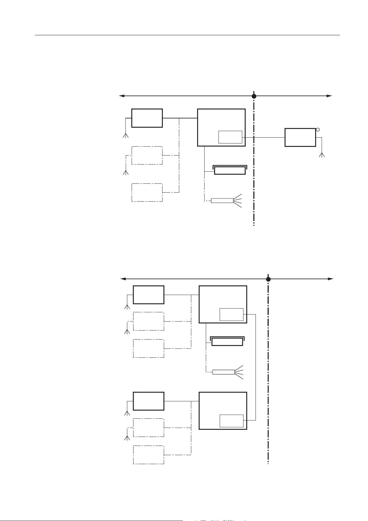
2.1.1 Configuration with interface converter ACM200 i n the safe area
Hazardous area
APS50.
PSUx
Battery
Pack
Ex-i
max. 48 m
Ex-i
max. 50 m
Ex-i
max. 3 m
IND226x
Interface
IND
Ex-i
max. 20 m
Analog weighing
platform
Ex-i
max. 20 m
System
solution
Analog Ex1
Wc
Wc
Wc
Wc
Safe area
Ex-i
max. 300 m
Das hed-line components are alternatives .
2.1.2 Configurati on with remote controll ed IND226 x ( second di splay)
RS232
ACM200
APS50.
PSUx
Battery
Pack
APS50.
PSUx
Battery
Pack
Hazardous area
Ex-i
max. 15 m
Ex-i
max. 50 m
Ex-i
max. 3 m
Ex-i
max. 15 m
(Second display)
Ex-i
max. 50 m
Ex-i
max. 3 m
IND226x
(Master)
Interface
IND
Ex-i
max. 20 m
Analog
Wheiging platform
Ex-i
max. 20 m
System solution
Analog Ex1
IND226x
Interface
Remote
Ex-i max. 300 m
Wz
Wz
Wz
Wz
Safe area
Das hed-line components are alternatives .
Operating i nstructions 7 2 203 9 52B 0 8 /1 0 7
Page 10
Intr oduction
2.2 Commissioning
2.2.1 Guide for installers and terminal di agram
The ins tallati on of an explosion-pr
wei ghing terminal may only be carri ed out in accordance with the guide for i ns tallers
ME-72 2 0 3 9 58 and control drawing ME- 72203 6 7 7 .
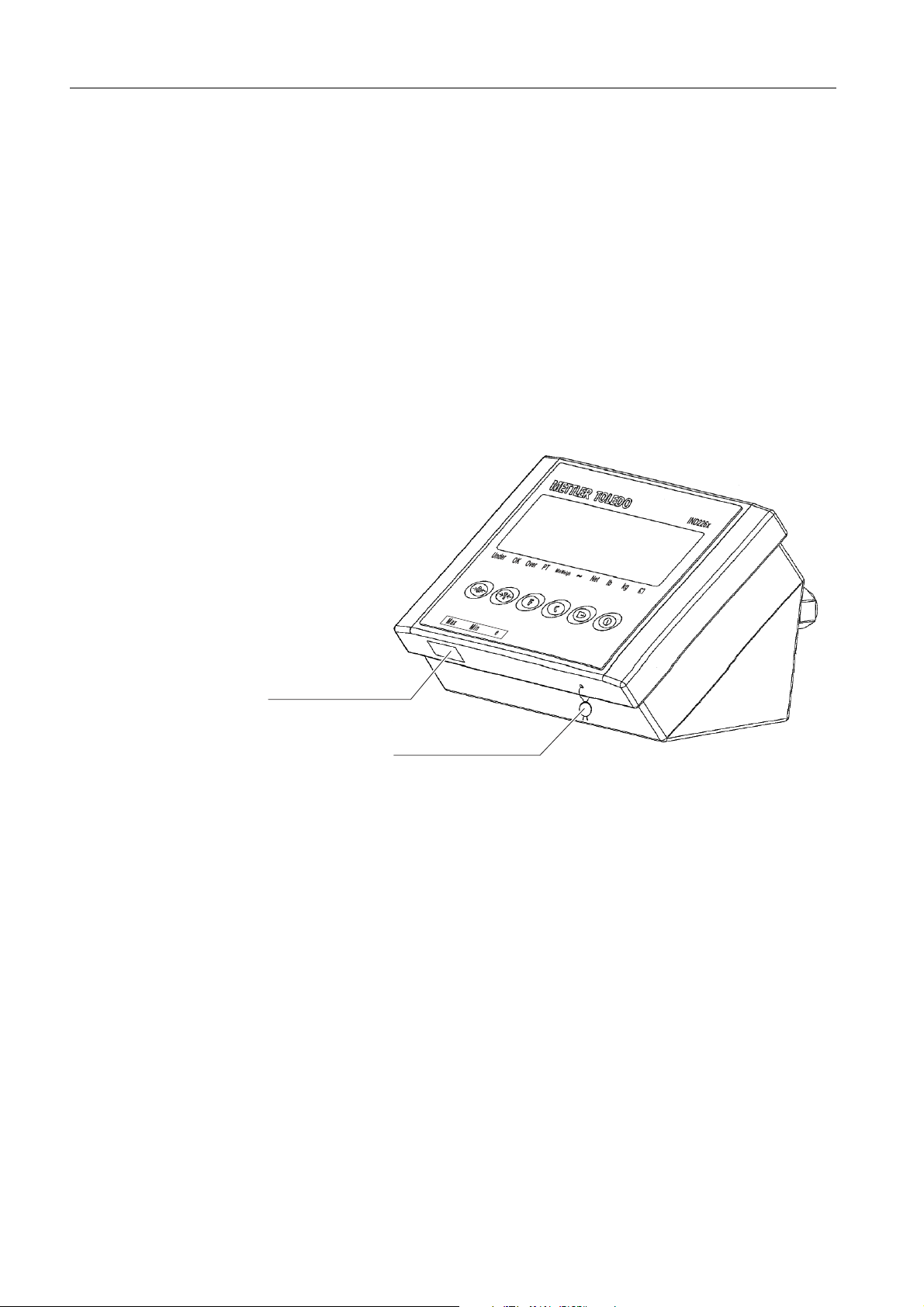
2.2.2 Information on certified weighing systems
In the cas e of certified wei ghing s ys tems , the weighi ng platform connection at the
wei ghing terminal mus t be s ealed with a wire seal or a veri ficati on mark. In addition,
a label with the information on "Max", "Min" and "e" has to be placed within the
range of vision of the weight display.
otected weighing s ystem with the IND2 2 6 x
IND2 26x
Veri ficati on mark
Wire seal
8 Operating ins tructions 7 2 203 9 52B 0 8 /1 0
Page 11

IND2 26x
2.3 Description
2.3.1 Overview
IND226x
+
–
Introducti on
1 6- digit weight dis play
2 S
tatus i ndicators
3 Keypad
2.3.2 Status indicators
LED Meaning
Under / OK / Over Indicators for check wei ghing
PT Indi cator for tare s pecification
MinWeigh Indicator for MinWei gh function
~ Movement indicator
Net The displayed weight value i
lb / kg Weight unit currently selected
+
–
S torage battery s tate
s a net weight val ue
Operating i nstructions 7 2 203 9 52B 0 8 /1 0 9
Page 12
Intr oduction
IND2 26x
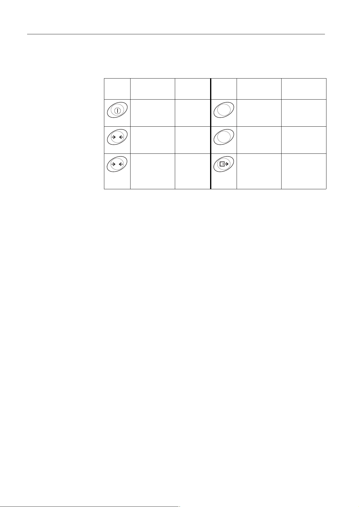
2.3.3 Keys
Key
Operating
mode
Switching
power on/off;
abort
Zeroing Scrolling
0
Tare Scrolling
T
Menu Key
–
back
forward
Operating
mode
Functi on key Back to the next
F
Cl ear key Back to the
C
T ransfer key
Long key-
pres s :
Calling
up menu
Menu
higher menu
item
previous menu
item
Acti vating
u item;
men
accepti ng
s e
lected s etting
10 Operating i nstructions 7 2 203 9 52B 0 8 /1 0
Page 13

IND2 26x
3 Basic functions
3.1 S witching on and off
S witching on
Basi c functions
➜ Pres s
The dis play lights up and then s hows the software number.
When the weight display appe
S witching off
➜ Pres
s and hold
3.2 Zeroing
Zeroing corrects the influence of s light s oil ing on the l oad plate.
S etting to zero manually
1. Unl oad weighing platform.
2. P res s
The zero dis play appears.
Automati c zeroing
In case of non-certified weighing platforms , the automatic zero point correction can
b
e deactivated in the s upervis or menu (F1.4.1 ) .
In standard operation, the z ero point of the
rected when the weighing platform is unloaded.
.
ars , the weighing terminal is ready for operation.
until –OFF– is dis played.
.
weighing pl atform is automatically cor-
3.3 S i mple weighing
1. P lace wei ghing sample on the weighing platform.
2. Wait until the motion indi cator goes out.
3. Read weighing res ult.
Operating i nstructions 7 2 203 9 52B 0 8 /1 0 1 1
Page 14

Basi c functions
IND2 26x
3.4 Weighing with tare
Taring
Place the empty container on the weighi ng platform
The zero dis play and the Net i ndicator appear.
and pres s
T
.
Cleari ng the tare
C
Pres s
The Net indi cator goes out, the gros s weight appears in the dis pl ay.
• If automatic clearing of the tare weight is s et
(F1.5.2=On), the tare weight is cleared automatically as s oon as the wei ghing
platform is unloaded to z ero.
• If tare interlock is s et in the s upervis or menu (F1.5.3=
only be cl eared when the weighing platform is unloaded to z ero.
.
i n the s upervis or menu
On), the tare weight can
Automati c tar ing
This function mus t be activated in
Place the empty contai ner on the weighing platform.
The weight applied on the weighing platform is automati cally saved as the tare
wei ght.
The zero dis play and the Net i ndicator appear.
the s upervis or menu (F1.5.1=On) .
3.5 Printing/transferring data
Condition
The weighing terminal is con
converter ACM2 00 in the s afe area.
Pres s
The display contents are pri nted out or
.
Note
The display contents wil l not be printed or trans ferred
nected via the optional Interface IND to the interface
transferred to a computer.
if the s cale is in motion.
12 Operating i nstructions 7 2 203 9 52B 0 8 /1 0
Page 15

IND2 26x
3.6 Informati on on storage battery operation
EXPLOSION HAZ ARD!
Al ways charge the B attery Pack in a s afe area!
Only us e chargers approved by MET T LER TOLEDO!
+
The indicator
ove
▼ ab
▼ ab
ove
▼ above
The (res idual) operating li fe during s torage battery operation depends on the
o
perating mode.
The foll owing operating life applies for a full y charged new storage battery:
Sleep mode min. 7 0 h
Normal wei ght display min. 6 0 h
Normal wei ght dis play and interface operation min. 5 0 h
–
i ndicates the s torage battery state.
+
–
continuous red Storage battery charged approx. 10%
Residual operating life approx. 3– 5 h
+
–
s low flas hing, red Storage battery charged approx. 5%
Residual operating life approx. 1 h
+
–
rapid flashing, red Storage battery charged les s than 5%
Storage battery mus t be charged immediately
Basi c functions
Note
Depending on the age and the charging s tate of the storage battery, the operating li fe
may vary downwards .
3.7 Cleaning
EXPLOSION HAZ ARD!
➜ Befor
Further notes on cleani ng
• Us e a damp cloth.
• Do not us e any aci ds , alkalis or s trong s olvents.
• Do not cl ean the weighing terminal using high-pres s ure or high-temperature water.
• Foll ow all the relevant instructions regarding cl eaning interval s and permis s ibl e
e cleaning ens ure that the weighing terminal i s clos ed properl y. The four clip
fas teners at the corners mus t have engaged fully.
clea
ning agents.
Operating i nstructions 7 2 203 9 52B 0 8 /1 0 1 3
Page 16

Applicati ons
4 Applications
IND2 26x
Depending on the s etting of F 2.1 parameter in the operator menu, different appl ica-
tions can be acti vated us ing the
F
key.
4.1 Displaying weight values with a higher resolution (x10)
For this purpose F2.1=MULt mus t be set i n the operator menu ( factory s etting).
Pres s
The weight value is displayed with a higher re
onds .
Note
The weight value in hi gher res olution ( x1 0 ) cannot be printed.
F
.
s olution ( x1 0 ) for about 1 0 sec-
4.2 S witching weight unit
For this purpose, F2.1=Unit must be s et in the operator menu.
Pres s
The weight value is displayed in the s e
Note
The displayed weight unit remai ns unti
14 Operating i nstructions 7 2 203 9 52B 0 8 /1 0
F
.
cond weight unit.
l it is s witched again.
Page 17

IND2 26x
Applications
4.3 Checkweighing
For this purpos e, F2.1=OVEr and F2.2.1=CHECh (factory s etting) mus t be s et
in the operator menu. In the factory s etting, the check weighing function is worki ng
with upper and lower tolerances of 1 0 d. With parameters F2.2.3 and F2.2.4 , thes e
tol erances can be cus tomiz ed.
S etting target weight
1. P res s
2. P res s and hold
appear.
If F2.2.2=W
dis play appears .
3. P ut the target weight on the weighing platform and save with
The OK indicator lights.
If F2.2.2=
ing las t digit appears .
4. Enter target weight us i ng the
(s ee page 18).
5. S ave entered weight value as target wei ght using the
F
to activate the check wei ghing function.
F
until tArGEt and the 3 indicators Under, OK and Over
EIGHt ( factory s etting) i s set in the operator menu, the weight
MAnUAL is s et i n the operator menu, the weight display with blink-
T
, and
F
keys and confirm with
F
key.
Check weighing
Ex ample: T arget weight = 1 .00 0 kg
• Weight i s les s than the target weight and
below the lower tolerance value.
The Under indicator lights.
F
.
• Weight is within the tolerance values .
The OK indicator li ghts .
• Weight is more than the target wei ght and
ab
ove the upper tolerance value.
The Over indicator lights .
S witching between checkweighing and nor mal weighi ng
Pres s
Operating i nstructions 7 2 203 9 52B 0 8 /1 0 1 5
F
to s witch between checkweighing and normal weighing.
Page 18

Applicati ons
4.4 Classifying
For this purpos e, and F2.2.1=CLASS mus t be s et in the operator
menu.
In the factory setting, the cl as s ifying function
ances of 10 d, 2 0 d, 3 0 d. With parameters F2 .2. 3 and
can be customiz ed.
S etting target weight
IND2 26x
i s worki ng with upper and lower toler-
F2 .2.4 , thes e tolerances
1. P res s
2. P res s and hold
appear.
If ( factory s etting) is s et in the
dis play appears .
3. P ut the target weight on the weighing platform and save with
The OK indicator lights.
If is s et i n the operator menu, t
ing las t digit appears .
4. Enter target weight us i ng the
(s ee page 18).
5. S ave entered weight value as target wei ght using the
F
to activate the classifying function.
F
until and the 3 indicators U nder, OK and Over
T
, and
operator menu, the weight
he weight dis play with bli nk-
F
keys and confirm with
F
key.
F
.
16 Operating i nstructions 7 2 203 9 52B 0 8 /1 0
Page 19

IND2 26x
Applications
Classifying
Ex ample:
Target weight = 1 ,00 0 kg, tol. 1 = 1 0 0 kg, tol. 2 = 2 0 0 kg, tol. 3 = 300 kg
• Weight i s les s than the target weight and
below tolerance 3, e.g. below 700 kg.
The Under indicator lights.
• Weight i s les s than the target weight
and
below tolerance 2 ,
e.g. between 7 0 0 kg and 8 0 0 kg.
The Under indicator lights.
• Weight i s les s than the target weight
and
below tolerance 1 ,
e.g. between 8 0 0 kg and 9 0 0 kg.
The Under indicator lights.
• Weight is within tolerance 1 ,
e.g. between 900 kg and 1 ,1 0 0 kg.
The OK indicator li ghts .
• Weight is more than the target wei ght and
above upper tolerance 1 ,
e.g. between 1 ,100 kg and 1 ,2 0 0 kg.
The Over indicator lights .
• Weight is more than the target wei ght and
ab
ove upper tolerance 2,
e.g. between 1 ,200 kg and 1 ,3 0 0 kg.
The Over indicator lights .
• Weight is more than the target wei ght and
ab
ove upper tolerance 3,
e.g. above 1,3 0 0 kg.
The Over indicator lights .
S witching between classi fying and normal wei ghing
Pres s
Operating i nstructions 7 2 203 9 52B 0 8 /1 0 1 7
F
to s witch between clas sifying and normal wei ghing.
Page 20

Operator menu
5 Operator menu
The operator menu consis ts of the following blocks:
F2 – F key menu s ettings
F3 – Terminal menu s etti ngs
F4 – Communication menu settings
F6 – Exit menu
5.1 Entering the operator menu
IND2 26x
In gros s mode, press and hold
Enter pas s word
SEtUP app
Pres s
ppears .
F2 a
ears.
.
5.2 Operati ng the menu
Keys and their functi on in the menu
T
Sel ecting next parameter.
Back to the previous parameter.
Confirming s electi on.
C
Back to the previous menu item.
F
Back to the next hi gher menu i tem.
Numeri c entry
until MAStEr appears.
and confirm with .
1. P res s
The (last) digit will blink.
2. Increase the dis played digit us ing the
– or –
Decrease the di s played digit us i ng the
3. When entering multi-digit numbers , us e the
place to the left.
4. Change the di git as des cribed in s tep 2 .
5. Repeat steps 3 and 4 if neces s ary.
6. When al l digits are entered, us e the
18 Operating i nstructions 7 2 203 9 52B 0 8 /1 0
for editing the displayed value.
F
T
key.
key.
F
key to move the curs or one
key to confirm the entry.
Page 21

IND2 26x
Operator menu
Note
With
C
, you can clear the entry.
5.3 F2 – F key menu
Factory s ettings are printed with bold characters .
F2 .1 – Function of the F key
3 different functi ons can be as s igned to the F key:
MUL10 When
F2 .2 – P lus/Mi nus weighing
Thes e parameters only appear if i s s et.
F2 .2 .1 – Operating mode
CHECh Check weighing
pres s ing the F key, the weight val ue i s di s played in 10 times hi g-
her resolution
When pres s ing the F key, the weight un
Note: lb is not poss ible in co
Plus /Minus weighing
Additi onal s etti ngs , s ee F2 .2
Clas s ifiying
it s witches between kg and lb
mpulsory- certification mode.
F2 .2 .2 – S etting the target wei ght
WEIGHt B y weighing in an actual sample weight
MAnUAL B y
F2 .2 .3 – Upper tolerances
After s electing the parameter, the currently s et tolerance value is displ
If F2.2.1 = Chech is s et:
Upper tolerance = target val ue + displaye
If F2.2.1 = CLASS is set:
Internall y the terminal calculates 3 tolerances .
Upper tolerance 1 = target value + dis played tolerance
Upper tolerance 2 = target value + 2 x displayed tolerance value
Upper tolerance 3 = target value + 3 x displayed tolerance value
1. If neces s ary, us e the
2. Change tolerance val ue us ing the
Factory s etting upper tolerance val ue = 10 d
Pos s ible settings 0 ... full load
numeric entry
F
d tolerance value
key to activate editing.
T
,
and
value
F
keys .
ayed.
Operating i nstructions 7 2 203 9 52B 0 8 /1 0 1 9
Page 22

Operator menu
F2 .2 .4 – Lower tolerances
After s electing the parameter, the currentl y s et tolerance val ue is displ
If F2.2.1 = Chech is set:
Lower tolerance = target value – dis pl ayed tolerance
If F2.2.1 = CLASS is set:
Internal ly the terminal calculates 3 tolerances .
Lower tolerance 1 = target value – displayed tolerance v
Lower tolerance 2 = target value – 2 x dis
Lower tolerance 3 = target value – 3 x dis
played tolerance value
played tolerance value
value
alue
IND2 26x
ayed.
1. Us e the
2. Change tolerance us ing the
Factory s etting lower tolerance value = 1 0 d
Pos s ible settings 0 ... full load
F2 .4 – Remote Display (IND22 6
The Interface Remote has to be ins tall ed in the
function.
The foll owing commands can be carried out optionally by the mas ter or the
s econdary dis play:
The cabling of the s ys tem components i s d
ME-72 2 0 3 6 77 of the IND226 x installation ins tructions.
OFF Remote functi on of the s e
ON R
F
key to activate editing if necessary.
T
,
and
F
keys .
x as secondary display)
s econdary di s play in order to us e this
S et to Zero, Tare, and Del ete.
es cri bed in the terminal diagram
condary di s play de-acti vated
emote function activated. T he secondary displ ay displays the wei ght
value of the mas ter termi nal.
F2 .5 – Active i nput
Please refer to the IND2 26x guide for ins tallers and the terminal diagram ME-
203677 for information on selecti ng and connecting external s witches or
72
pus hbuttons to the active input.
The active i nput can have one of t
he following functions ass igned to it:
None Acti ve i nput de-activated
Clear Delete
Print T ransfer ke
Tare Tare
Zero Zero-adjustme
F2 .6 – Mi nWeigh
When the MinWeigh function i s activated, the MinWeigh i ndicator lights up when the
wei ght l
F2 .6 .1 – Activation of the Mi nWeigh function
ies below the minimum weighing-in quantity.
key
y
key
nt key
MinWeigh function de-acti vated
ON MinWeigh function activated
20 Operating i nstructions 7 2 203 9 52B 0 8 /1 0
Page 23

IND2 26x
Operator menu
F2 .6 .2 – Input mode
The minimum weighi ng-in quantity can be entered directly or be calculated directly
by t
he terminal from the foll owing variabl es :
Measurement uncertainty when the l oad approaches 0
U
0
T Requi red tolerance as a %
F S afety factor
dirEct Enter minimum weighing- in quantity via keyboard
The minimum weighi ng-in quantity is cal
culated by the terminal
F2 .6 .3 – Di rect entr y of the mini
This parameter is only dis played if F2.
Enter the minimum wei ghing-in quantity by us ing the keys
F2 .6 .4 – Entry of the meas urement uncertainty U
This parameter is only dis played if F2.6.2 = CoMPon has been sel ected.
Enter the measurement uncertainty by us ing the keys
mum weighing-in quantity
6.2 = dirEct has been s elected.
0
T
,
and
T
,
and
F
F2 .6 .5 – Entry of the tolerance T
This parameter is only dis played if F2.
Enter the tolerance as a % by us ing the keys
Factory s etting 0.1%
Pos s ible val ues 0.1 ... 9 9 .9%
6.2 = CoMPon has been s elected.
T
,
and
F
.
F2 .6 .6 – Entry of the safety factor F
This parameter is only dis played if F2.6
Enter the safety factor by us ing the keys
Factory s etting 1
Pos s ible val ues 1 ... 1 0
.2 = CoMPon has been s elected.
T
,
and
F
.
F
.
.
F2 .1 0 – Reset F key setti ngs
Reset all parameters F2 .x(.x) to fac
Operating i nstructions 7 2 203 9 52B 0 8 /1 0 2 1
tory setting.
Page 24

Operator menu
5.4 F3 – terminal menu
Factory s ettings are printed with bold characters .
F3 .1 – Di spl ay setti ngs
F3 .1 .1 – S leep mode
The weighing terminal switches to s leep mode when during the set time no action on
the weighing termi nal or no change i n weight occurred.
Factory s etting 60 (s econds )
Functi on disabled 0
Pos s ible settings 10 ... 999 (s econds )
F3 .2 – Auto power off
The weighing terminal i s s witched off if during the set ti
wei ghing terminal or on the weighing platform.
Factory s etting 5 (minutes)
Functi on disabled 0
Pos s ible settings 0 .5 ... 6 0 (mi nutes )
IND2 26x
me no action was on the
F3 .1 0 – Reset terminal settings
Reset all parameters F3 .x(.x) to fac
5.5 F4 – communicati on menu
The Interface IND data interface has to be ins talled in the IND226x in order to us e this
function. In addition an interface converter ACM2 00 is required for communication
with PCs or printers in the s afe area.
Factory s ettings are printed in bold characters.
F4 .1 – Connections
When pressing
APrint S tab
SICS C
Contin T ol
F4 .2 – Format
le wei ght values are pri nted automati call y
Additi onal s etti ngs : F4. 2.5 and F4. 2.6
ommunicati on via the METT LER T OLEDO Standard Interface Command
S et (MT -S ICS )
edo Continuous Mode – for continuous trans fer of weight data and
s tatus i nformation, for exampl e to a PC or a secondary dis play.
tory setting.
, the current dis play is pri nted.
F4 .2 .1 – Line format
Multi li ne
SinGLE S ingle line
22 Operating i nstructions 7 2 203 9 52B 0 8 /1 0
Page 25

IND2 26x
Operator menu
F4 .2 .2 – P ri nt format
Standar d ( current display)
OVEr over / good / under
Count P iece number
F4 .2 .3 – P ri nt l anguage
Engli sh
CHn Chines e
F4 .2 .4 – Add line feed
Factory s etting 3 (li nes)
Pos s ible settings 0 ... 9 ( lines )
F4 .2 .5 – Auto pri nt threshold
This menu item is only avail able if F4.1=APrint is s et.
A s table weight value which i s higher than the s et value is printed automati cally.
Factory s etting 10 (d)
Pos s ible settings 0 ... max. load
F4 .2 .6 – Auto pri nt reset threshold
This menu item is only avail able if F4.1=APrint is s et.
The s cale mus t be unloaded below the set value before a new weight value can be
printed automati cally.
Factory s etting 10 (d)
Pos s ible settings 0 ... max. load
F4 .3 – P arameters
F4 .3 .1 – Baudrate
1200
2400
4800
9600
19200
F4 .3 .2 – Data bi ts / parity
7-odd 7 bi ts , parity odd
7-even 7 bits , parity even
8-nonE 8 bits , no parity
8 bits, parity odd
8 B its , parity even
F4 .3 .3 – Xon/Xoff
Xon/Xoff enabled
OFF Xon/Xoff dis abled
Operating i nstructions 7 2 203 9 52B 0 8 /1 0 2 3
Page 26

Operator menu
F4 .3 .4 – Checksum
Checks um enabled
OFF Chec
ks um disabl ed
F4 .1 0 – Reset communicati on setti ngs
Reset all parameters F4 .x(.x) to fac
5.6 F6 – ending menu
IND2 26x
tory setting.
1. P res s
F6 a
2. T o s ave changes : Pres s
SAVE ap
Then press
– or –
To reject changes : Pres s
C
ppears .
pears.
.
again.
AbOrt appears.
Pres s
.
.
T
.
24 Operating i nstructions 7 2 203 9 52B 0 8 /1 0
Page 27

IND2 26x
6 S upervisor menu
In addition to the blocks of the us er menu, the following blocks can be acces s ed in
the Technician menu:
F1 – Scale settings
F5 – Terminal s etti ngs
F6 – Exit menu
6.1 Entering Supervisor menu
S upervis or menu
1. In gross mode, pres s and hold
T
1. Enter password
SEtUP
1. P res s
F1 a
appears in the dis play.
.
ppears i n the dis play. Al l parameters can be modified.
Information for certified weighing sy
The parameters F1 , F5 .1 und F5 .4 are dis abled at ce
Proceed as follows in order to change thes e parameters:
1. S witch off wei ghing terminal and open.
2. Us e a jumper to clos e the W&M solder bridge on the mainboard.
3. Clos e the cover and switch on
SEtUp
4. S ave the modified configuration ( F6) .
5. S witch off wei ghing terminal and open.
6. Open the W&M s older bridge by removing the jumper.
7. Clos e the cover and seal th
is displayed. All the parameters can be modified.
appears in the di s play.
e weighing terminal.
until MAStEr appears in the display.
T
and confirm with .
stems (OIML or NTEP)
rtified weighing s ys tems .
the weighing terminal.
6.2 Operati ng the S upervisor menu
Operating the Supervisor menu is the same as in the Operator menu, s ee page 1 8 .
Operating i nstructions 7 2 203 9 52B 0 8 /1 0 2 5
Page 28

S upervis or menu
IND2 26x
6.3 Block F1 – S cale
Factory s ettings are printed in bold letters .
F1 .1 – Approval
no no approval
approval according to OIML
approval according to NT EP
for other approvals
F1 .2 .1 – Wei ght units
1 wei ght unit: kg
wei ght unit: lb 1 lb ≈ 0.454 kg
F1 .2 .3 – Capacity
Pos s ible capaci ties and the factory settings depend on the weighing platform con-
nected.
If neces s ary, modi fy the di s played val ue.
Factory s etting 3 kg
F1 .2 .4 – Resol ution
Pos s ible res olutions and the factory s ettings depend on the weighing platform con-
nected.
1. If neces s ary, modify the dis played value.
Factory s etting 0.001 kg
F1 .3 .1 – Geo value
Adaptation of the weighing platform to the geographi cal location, see table in the
annex.
Pos s ible settings 0 ... 3 1
Factory s etting 16
F1 .3 .2 – Linearization during adjustment
LinOFF Lineariz ation dis abl ed
LinOn L ineariz ati on enabled ( 3 point li nearization)
26 Operating i nstructions 7 2 203 9 52B 0 8 /1 0
Page 29

IND2 26x
F1 .3 .3 – Adjustment
The s teps with grey background only appear
Display Key Description
S upervis or menu
i f parameter is s et.
E SCL
10 CAL
...
0 CAL
Add Ld
000000
003000
10 CAL
...
0 CAL
FULL Ld
000000
006000
10 CAL
...
0 CAL
donE
F1.4
Unload weighing platform
T
T
Confirm empty weighing platform
The weighing terminal counts down from 1 0 to 0.
The zero point is determi ned
Load half of the maxi mum l oad
Confirm half load
Enter weight value for half maximum load
Enter weight value
F
Weight value for half of the maximum l oad
entered
Confirm weight val ue
The weighing terminal counts down from 10 to 0 .
Half maximum load is adjus ted
Load maxi mum l oad
Confirm maximum load
Enter weight value of maximum load
Enter weight value
F
Weight value for maximum load entered
Confirm weight val ue
The weighing terminal counts down from 10 to 0 .
Max imum load is adjus ted
Adjus tment fini s hed. T his message is di s played
for about 2 s econds
Next block in the supervis or menu
Operating i nstructions 7 2 203 9 52B 0 8 /1 0 2 7
Page 30

S upervis or menu
IND2 26x
F1 .3 .4 – CalFREE
The CalFR EE procedure can be us ed at tank and s il o s cales . It is us ed to precalibrate
t
he weighing s ys tem without calibration weights.
CalFREE offers s imple and rapi d calibration when the use of calibration weights is not
ossible or when the readability > 0.2 % of the weighing capacity. T he CalFREE
p
procedure calibrates only the internal A/D converter of the IND226 x. Mechanical
influences and vibrations are not compens ated.
In order to achieve the bes t res ults we recommend interconnecti ng the i ndividual
wei ghing cells via a juncti on PCB without rotary potentiometers.
F1 .3 .4 .1 – Entering the total weighi ng cel l capacity
The total weighing cell capacity E
i s the total of the individual capacities .
max
Determine the total weigh
F
keys to enter it.
Example 4 weighi ng modules with
ing cell capacity E
max
500 kg each res ult in a total weighing cell capaci ty E
2000 kg.
F1 .3 .4 .2 – S electing the weight unit of the weighing cell capaci ty
1 kg
lb
F1 .3 .4 .3 – Entering the mean value of the output si gnals
Determine the mean value up to 3 d
F
keys to enter it.
Permi s s ible values : 0 to 3 mV/V
Example Weighing module 1 output signal S1 = 1 .990 mV/V
Weighing module 2 output s i gnal S2 = 2 .0 0 2 mV/V
Weighing module 3 output s i gnal S3 = 1 .9 9 8 mV/V
Weighing module 4 output s i gnal S4 = 1 .9 9 5 mV/V
ecimal places and us e the
and use the
T
,
and
=
max
T
,
and
Mean value from S1 ... S 4 S = 1 .996 mV/V
F1 .3 .4 .4 – Entering the preload range of the weighi ng s ystem
Enter the preload range by using the keys
28 Operating i nstructions 7 2 203 9 52B 0 8 /1 0
T
,
and
F
.
Page 31

IND2 26x
F1 .3 .4 .5 – S tarting the CalFREE pr ocedure
Display Key Description
E SCL
Unload weighing platform
S upervis or menu
Confirm empty weighing platform
The weighing termi nal counts downwards from
10 to 0
The internal A/D converter is calibrated
CalFREE procedure terminated, return to F1 .3
10 CAL
...
0 CAL
F1.3
F1 .4 .1 – Automatic zero setti ng
Automati c z ero s etti ng di s abled
0.5 d Aut
omatic zero setting within +/–0.5 d
Automatic zero s etti ng within + /–1 .0 d
Automatic zero s etti ng within + /–3 d
F1 .4 .2 – P ower up zero
Power up zero di s abl ed
Power up zero within + /– 2 %
10 P
ower up z ero within +/–10 %
Power up zero within + /– 20 %
F1 .4 .3 – P ushbutton zero
Pus hbutton z ero di s abled
2 P
us hbutton zero with +/–2 % zero setti ng range
Pushbutton z ero with + /–1 0 % z ero s etti ng range
Pushbutton z ero with + /–2 0 % z ero s etti ng range
F1 .5 .1 – Automati c tari ng
Automatic taring enabl ed
OFF Au
tomati c taring disabled
F1 .5 .2 – Auto clear tare
Clearing tare automatically enabled
OFF C
learing tare automaticall y dis abl ed
F1 .5 .3 – T are Interl ock
The weighing platform mus t be unloaded to z ero before the tare weight
can be cleare
OFF Function d
Operating i nstructions 7 2 203 9 52B 0 8 /1 0 2 9
d.
isabl ed
Page 32

S upervis or menu
IND2 26x
F1 .5 .4 – Auto tar e threshol d
This menu item is only available if is s et.
The weighing platform mus t be loaded to the s et value before the weight value is
automatical ly tared.
Factory s etting 10 d
Pos s ible settings 0 ... maximum load
F1 .5 .5 – Auto clear tar e threshold
This menu item is only available if is s et.
The weighing platform mus t be unloaded below the s et value before a new weight
value can be tared automaticall y.
If is s et, the weighing platform mus t be unloaded to the s et value
before the tare val ue i s cleared automatically.
Factory s etting 10 d
Pos s ible settings 0 ... maximum load
F1 .5 .6 – Restart
If the Restart function is activated, the las t zero point and the tare value are stored.
The termi nal operates with the stored zero point and tare value after it has been
s witched off and on or after a power interruption.
OFF Res tart function de-activated
Restart function activated
F1 .6 .1 – Di gi tal fil ter
The digital filter s tabiliz es the weight dis play when the l oad is moving or vibrating.
Low fil ter
MEd Medium filter
High filter
F1 .6 .2 – Motion detection
0.5 d Motion detection within + /–0.5 d
Motion detection withi n + /–1 d
Motion detection withi n + /–3 d
F1 .1 0 – Resetti ng parameters 1.x(.x) to factory setting
Onl y parameter s ettings are res et, the adjus tment is s aved.
30 Operating i nstructions 7 2 203 9 52B 0 8 /1 0
Page 33

IND2 26x
6.4 Block F5 – Maintenance
Factory s ettings are printed in bold letters .
F5 .1 – Di spl ay of cali bration values
In this menu the foll owing calibra
F5 .1 .1 – S how zero-counts
F5 .1 .2 – S how half load weight value
F5 .1 .3 – S how half load counts
F5 .1 .4 – S how full load weight value
F5 .1 .5 – S how full load weight counts
F5 .2 – Keypad test
The termi nal s hows PrESS.
S upervis or menu
tion values can be cal led up:
Pres s
Pres s
T
to exi t keypad tes t.
C
F
.
F5 .3 – Di spl ay test
Al l display s egments light up.
F5 .4 – Internal resolution of the dis play
The current weight value is di s played in "R awCounts " .
F5 .5 – COM1 test
To this purpos e the terminal
converter ACM2 00 In addition the Interface IND data interface has to be ins talled in
the IND2 26x.
has to be connected to a computer via the interface
F5 .6 – T esti ng the digital i nput
The digital input is tes ted.
F5 .7 – P ri nt setup
Output all the parameters via
the data interface.
Operating i nstructions 7 2 203 9 52B 0 8 /1 0 3 1
Page 34

S upervis or menu
F5 .8 – Entering the seri al number
The 10-digit s eri al numbe
r of the weighing terminal has to be entered in 2 blocks in
the revers e order.
1. Activate F5 .8.
H – i s
dis played in the di s play.
2. Enter the firs t 5 digits of the serial number in the reverse order
(Digit 5 , ... Digit 1 ).
3. P res s
L – i s
T
.
dis played in the di s play.
4. E nter the las t 5 digits of the serial number in the reverse order
(Digit 1 0, ... Di git 6).
F5 .1 0 – General reset
Reset all parameters of groups F1 to F4 to factory s ettings
.
IND2 26x
32 Operating i nstructions 7 2 203 9 52B 0 8 /1 0
Page 35

IND2 26x
7 Interface commands
7.1 S ICS interface commands
The weighing terminal s upports the MT -S ICS ( MET TLE R TOLEDO S tandard Interface
Command Set) command set. With S ICS commands, it is pos s i ble to configure,
query and operate the termi nal from a PC. SICS commands are divided up into vari-
ous levels.
For further information about the MT -SICS command s et, s ee MT -S ICS Manual ( Order
No. 0 0 705 184) or contact the METTL ER T OLEDO Cus tomer Service.
LEVEL 0 @ R es et the scale
Interface commands
Command Meaning
I0 Inquiry of all available S ICS commands
I1 Inquiry of S ICS l evel und S ICS version
I2 Inquiry of s cal e data
I3 Inquiry of s cale s oftware vers ion
I4 Inquiry of s erial number
S Send s table weight value
SI Send wei ght value immediately
SIR Send weight value immediately and repeatedly
Z Zero the s cale
ZI Zero i mmediately
LEVEL 1 T Tare
TAC Clear tare
TI T are i mmediately
Operating i nstructions 7 2 203 9 52B 0 8 /1 0 3 3
Page 36

Interface commands
7.2 Toledo Continuous Mode
The weighing terminal s upports the Toledo Continuous Mode for continuous trans fer
of weight data and s tatus informati on, for example to a PC or a s econdary dis play.
At a baud rate of 2 4 00 bauds and higher, a data s tring is transferred approximately
9
times per s econd. The transfer rate i s s lower if the baud rate is lower.
7.2.1 Toledo Continuous commands
Command Meaning
P Print out the current result
T Tare the s cale
Z Zero the dis pl ay
C Clear the current value
U Switching the weight unit
IND2 26x
7.2.2 Toledo Continuous output format
Weight values are always trans mit
STX SB1 S B2 SB3 DF1 DF2 CR CHK
STX AS CII characters 0 2 hex/2 deci, character for "s tart of text"
SB. .. F or s tatus bytes, see below
DF1 Data field with 6 digits for the weight value (gross or net),
trans mi tted without a decimal point and unit,
leading z eroes replaced by blank s paces
DF2 Data field with 6 digits for the tare wei ght;
trans mi tted without a decimal point and unit,
leading z eroes replaced by blank s paces
CR Carri age return ( AS CII character 0D hex/1 3 deci)
CHK Checks um (2-part compl ement of bi nary s um of 7 l ower bits of al l
revious ly trans mitted characters , incl uding STX and CR),
p
trans mi tted only if activated in the menu
ted in the following format:
34 Operating i nstructions 7 2 203 9 52B 0 8 /1 0
Page 37

IND2 26x
Interface commands
S tatus byte S B1
Bi t 6 B it 5 Bi t 4 Bit 3 Bit 2 Bi t 1 Bit 0
0 1 Rounding / Increment Deci mal pos ition
Bi t 4 Bit 3 Roundi ng/
Increment
0 1 x1 0 0 0 XXXX0 0
1 0 x2 0 0 1 XXXXX0
1 1 x5 0 1 0 XXXXXX
Bi t 2 B it 1 Bi t 0 Decimal
pos ition
0 1 1 XXXXX.X
1 0 0 XXXX.XX
1 0 1 XXX.XXX
1 1 0 XX.XXXX
1 1 1 X.XXXXX
S tatus byte S B2
Bi t 6 B it 5 Bit 4 Bit 3 B it 2 B it 1 Bit 0
1 1 0lb 0 S tabili za-
tion
1kg 1Movement 1 Underload/
0Normal
s tatus
overl oad
0 Pos iti ve
s ign
1 Negati ve
s ign
0Gross
value
1Net
value
S tatus byte S B3
Bi t 6 Bi t 5 Bi t 4 Bi t 3 Bi t 2 Bi t 1 Bi t 0
0 1 0 Normal s tatus 0 Normal s tatus Weight unit
1 High res olution ( x 10) 1 Print request
Bi t 2 Bit 1 Bit 0 Weight unit
0 0 0 kg / lb ( SB2 Bi t 4)
0 0 1 g
0 1 0 t
0 1 1 oz
1 0 0 ozt
1 0 1 dwt
1 1 0 ton
1 1 1 free unit
Operating i nstructions 7 2 203 9 52B 0 8 /1 0 3 5
Page 38

Er ror mess ages
8 Error messages
Er ror code Error Remedy
Err 3 • EEP ROM error Turn the weighing terminal off and on
Err 6 • EEP ROM read/write error Call METTL ER T OLEDO Service
IND2 26x
Err 3 2 • Impermi s s ible values entered in Block
F1
Err 3 5 • Wei ghing platform in motion when cali-
brating
Err 7 0 • Keypad error Call MET T LER T OL EDO Service
EE E • In case of certified wei ghing platforms :
Z
ero s etting range exceeded duri ng
s witchi ng on
–EEE • In case of certified wei ghing platforms :
Ze
ro s etting range below li mit during
s witchi ng on
no DTA • Secondary dis play does not receive any
d data
vali
•Underload
Repeat the entry with correct values
If the mes sage i s di s played agai n,
inf
orm the METTLER TOLEDO Service
Ens ure that the weighing platform i s
s t
able
Unload weighing platform
Place the l oad plate on ( correctly)
Check the communication s ettings
Check data cable connec
If the mes sage i s di s played agai n,
inf
orm the METTLER TOLEDO Service
Pres s
tions
Weighing terminal
s wit
ches off
automati cally
Weighing terminal
remains dark after
being s witched on
If the mes sage reappears, call
MET TLE R TOLEDO Service
•Overload Decreas e load
• Zero s etti ng outside zero s etti ng range Unl oad weighing platform
• Cannot perform the key function Go back to gross mode
• Cannot perform the key function, s cale is
in moti on
• Automatic switching-off activated
• Battery level too low
• No or incorrect voltage s upply Check s upply unit connection
Ens ure that the weighing platform i s
s table
Unload the weighing platform and, if
appropriate, configure Dis play Timeout
and Power Off differently
Charge the B attery Pack
Call the METTL ER T OLEDO Service
36 Operating i nstructions 7 2 203 9 52B 0 8 /1 0
Page 39

IND2 26x
9 Technical data and accessories
9.1 Technical data
Expl osion pr otection IND22 6x, Interface IND, Interface Remote
Ignition protecti on type AT EX II 2G Ex ib IIC T4
II 2 D Ex tD A2 1 T 6 0 °C
CFMUS
Metrological data
Input s ignal range 0 to 3 mV/V
Supply voltage 5 V
IS Clas s I, II, III, Div. 1 , Group A, B, C, D, E, F, G / T4 Ta 4 0 °C
Technical data and access ories
Weighing platform
impedance
Smalles t perm. certi f. i ncr. 0 .80 μV/e
Fraction of the error li mit
(P
)
i
Number of weighing cells max. 4
Max . number of certifiable
increment values
Scale configuration Single range (SR)
87.5 . .. 1 0 5 0 Ω
0.5
≤ 6 0 0 0 e
Maxi mum cabl e length
Weighing platform –
IND2 2 6x
AP S50. – IND226x max. 1 5 m
PSUx – IND226x max. 5 0 m
Battery Pack – IND2 2 6 x max. 3 m
ACM200 – IND2 2 6 x max. 300 m
max. 20 m
Operating i nstructions 7 2 203 9 52B 0 8 /1 0 3 7
Page 40

Technical data and accessories
General technical data
Dis play Weight value: 7 - s egment dis play, 6 digits , 30 mm high
Status indicati on: 1 0 indicators
Hous ing s tai nless s teel
Protection type IP6 6
Power s upply AP S500/501 power s upply unit
alternatively via ex ternal Battery Pack or P SUx
Data i nterface 1 s erial intrins i cally safe data interface:
Interface IND for communication with perip
Al ternatively: Interface Remote for operating the IND
heral devices in the safe area
226x as a s econdary dis play
Digital inputs 1 digital input
IND2 26x
Weight
2.5 kg
(incl. packaging)
Ambient condi tions
Operating temperature –10 ... +40 °C
Storage temperature – 2 0 ... + 60 °C
Relati ve humidity 1 0 ... 8 5 % , non-condens ing
Operating altitude up to 2 000 m above sea level, indoors
Dimens ions
220
150
Under
OK
Over
PT
MinWeigh
Net
lb kg
38°
90
M5
66
132
148
Dimensions in mm
38 Operating i nstructions 7 2 203 9 52B 0 8 /1 0
Page 41

IND2 26x
9.2 Technical data for ACM20 0
Expl osion protection
Ignition protecti on type EN II (2) GD [E x ib] IIC
CFMUS
General technical data
Hous ing Stainless s teel
Protection type IP6 6
Power s upply Wide range power s upply unit 1 0 0 ... 2 4 0 VAC 50/60 Hz
Data i nterface RS 2 3 2
AIS Clas s I, II, III; Di vis i on 1; Group A, B, C, D, E, F, G
Technical data and access ories
Weight
(incl. packaging)
3,4 kg
Ambient condi tions
Operating temperature –10 ... +40 °C
Storage temperature – 2 0 ... + 60 °C
Relati ve humidity 1 0 ... 8 5 % , non-condens ing
Connection cables
Cable to IND2 2 6 x 10 m, premounted at the factory, intrins ical l
Cable to peripheral devices 1 0 m, premounted at factory, RS
Power connecti on cable 2 .4 m, with earthi ng-pin plug
232 Sub-D connector (female)
Dimens ions
160
175
R3.5
69.5
y s afe, with M16x 1.5 screwing
R5
81
200
Dimensions in mm
Operating i nstructions 7 2 203 9 52B 0 8 /1 0 3 9
Page 42

Technical data and accessories
9.3 Accessories
Accessories Description Or der number
IND2 26x
Interface IND Serial data interface (active) for ins tallation in the
226x, communicati on with peri pheral devices in the
IND
s afe area
Interface Remote Serial data interface (pas s ive) for i ns tal
lation in the
IND2 2 6x, remote function of the IND226 x
Scale s tand for
A4 3 0 x
PB
For mounting the weighing terminal to the weighi ng
platform, s tainles s
Height 330 mm
Height 660 mm
Floor stand For free ins tallati on of the weighing terminal
including mounting material for s crewing to the floor,
s tai nless, rus tproof
Stand bas e For movable ins tall ation of th
Wall bracket For mounting the weighing termi
e floor s tand, rustproof 0 0 50 3 70 1
nal to the wall,
including mounting screws , rus tproof
Bench s tand S For fas tening the wei ghin
g terminal to
PBA4 3 0x, 6 0 0 x 8 0 0 mm, rus tproof
ID retai ner For mounting the weighi ng terminal to the s haft of the
pallet s cale PT A4 5 9
x
22 0 1 8 0 1 9
22 0 1 8 0 2 0
22 0 1 0 3 3 4
22 0 1 0 3 3 5
00 5 0 4 1 3 2
00 5 0 4 1 3 0
00 5 0 4 1 2 8
22 0 1 2 1 9 6
40 Operating i nstructions 7 2 203 9 52B 0 8 /1 0
Page 43

IND2 26x
10 Appendi x
10.1 Disposal
Appendix
In conformance with the European Directive 20 0 2 /9 6 /EC on Was te Electrical and
El ectronic Equipment (WEEE), this device may not
This also applies to countri es outside the EU as per their specific regulations .
Please dis pos e of this product in accordance with l ocal regulations at the collect-
ing point specified for el ectrical and electronic equipment.
If you have any ques tions, pleas e contact the res ponsible authority or the dis tributor
f
rom which you purchased this device.
Should this device be pas s ed on to other parties (for
content of thi s regulation mus t also be related.
Thank you for your contribution to environmental prote
be dis posed of in domes ti c waste.
private or profes s ional us e) , the
ction.
Operating i nstructions 7 2 203 9 52B 0 8 /1 0 4 1
Page 44

Appendix
10.2 Decl arations of conformity
METTLER TOLEDO
Legal Metrology
Declaration of Conformity
Konformitätserklärung
Déclaration de conformité
Declaración de Conformidad
Conformiteitsverklaring
Dichiarazione di conformità
________________________________________________________________________________________________________
We, Wir, Nous, Nosotros, Wij ˈNoi
Mettler-Toledo (ChangZhou) Measurement Technology Ltd.
111 West TaiHu Road, XinBei District, ChangZhou, JiangSu, 213125, P.R.China
Declare under our sole responsibility that the product,
erklären, in alleiniger Verantwortung, dass dieses Produkt,
déclarons sous notre seule responsabilité que le produit,
declaramos, bajo nuestra sola responsabilidad, que el producto,
verklaren onder onze verantwoordelijkheid, dat het product,
dichiariamo sotto nostra unica responsabilitá, che il prodotto,
Model/Type: IND226x weighing terminal (EC test certificate: TC6862)
to which this declaration relates, is in conformity with the following standard(s) or other normative document(s).
auf das sich diese Erklärung bezieht, mit der/den folgenden Norm(en) oder Richtlinie(n) übereinstimmt.
Auquel se réfère cette déclaration est conforme à la (aux) norme(s) ou au(x) document(s) normatif(s).
Al que se refiere esta declaración es conforme a la(s) norma(s) u otro(s) documento(s) normativo(s).
Waarnaar deze verklaring verwijst, aan de volende norm(en) of richtlijn(en) beantwoordt.
A cui si riferisce questa dichiarazione è conforme alla/e sequente/i norma/e o documento/i normativo/i.
EC marking EC Directive: Applicable Standards.
2004/108/EC
For non-automatic weighing instrument used in an Article 1,2.(a) application ,additional metrological marking
according to Annex IV of Council Directive 2009/23/EC must be attached to the instrument.
1) Certificate issued by EXAM BBG Prüf-und Zertifizier GmbH., 44809 Bochum, Germany, notified body no. 0158
2) Applies to certified non automatic weighing instruments only in connection with approved load cells
gilt nur für geeichte Waagen in Verbindung mit zugelassenen Wägezellen
valable uniquement pour les balances vérifiées avec des cellules de charge homologuées
sola aplicable a balanzas verificadas en combinación con células de carga aprobadas
la dichiarazione vole sola per le bilance omologate in collegamento con celle die carico approvate
EMC
94/9/EC
ATEX
2009/23/EC
Non-automatic weighing
instruments
Issued on: 2007-12-1 Revised on: 2010-7-16
Mettler-Toledo (ChangZhou) Measurement Technology Ltd.
EN61000-6-1
EN61000-6-3
EN61000-4-3(10V/m)
EN61000-4-6(10V/m)
EN 60079-0: 2006
EN 60079-11: 2007
EN 61241-0: 2006
EN 61241-1: 2004
EN 45501:1992 /AC:1993 2
EXAM BBG 1)
BVS 07 ATEX
E015
)
IND2 26x
42 Operating i nstructions 7 2 203 9 52B 0 8 /1 0
Page 45

IND2 26x
Mettler-Toledo (ChangZhou) Scale System Ltd.
EC-Declaration of Conformity
EC-Konformitätserklärung
EC-Déclaration de conformité
EC-Declaración de Conformidad
EC-Conformiteitsverklaring
EC-Dichiarazione di conformità
________________________________________________________________________________________________________
We, Wir, Nous, Nosotros, Wij, Noi
Mettler-Toledo (ChangZhou) Scale System Ltd.
No.111, West Tai Hu Road, XinBei District, ChangZhou, JiangSu, 213125, P.R.China
declare under our sole responsibility that the product,
erklären, in alleiniger Verantwortung, daß dieses Produkt,
déclarons sous notre seule responsabilité que le produit,
declaramos, bajo nuestra sola responsabilidad, que el producto,
verklaren onder onze verantwoordelijkheid, dat het product,
dichiariamo sotto nostra unica responsabilitá, che il prodotto,
Model/Type: ACM200 Communication module
To which this declaration relates , is in conformity with the following standard(s) or other normative document(s),
auf das sich diese Erklärung bezieht, mitder/den folgenden Norm(en) oder Richtlinie(n) übereinstimmt.
Auquel se réfère cette déclaration est conforme à la (aux) norme(s) ou au(x) document(s) normatif(s).
Al que se refiere esta declaración es conforme a la(s) norma(s) u otro(s) documento(s) normativo(s).
Waarnaar deze verklaring verwijst, aan de volende norm(en) of richtlijn(en) beantwoordt.
A cui si riferisce questa dichiarazione è conforme alla/e sequente/i norma/e o documento/i normativo/i.
EC Directive Applicable Standards
94/9/EC Directive
2006/95/EC
Low Voltage Directive
2004/108/EC
EMC Directive
2002/95/EC
RoHS Directive
* * ATEX certificate: BVS 07 ATEX E 149, EXAM 0158, 44809 Bochum, Germany
No.111, West TaiHu Road, XinBei District , ChangZhou, JiangSu. 213125,PRC, Nov 7, 2007,Mettler-Toledo (ChangZhou) Scale &
System Ltd.
Yang JiaWu
EN60079-0:2006
EN60079-11:2007 **
EN61010-1˖2001
EN61000-6-1
EN61000-6-3
EN61000-4-3(10V/m)
EN61000-4-6(10V/m)
N/A
Quality Assurance Manager
Appendix
Operating i nstructions 7 2 203 9 52B 0 8 /1 0 4 3
Page 46

Congratulations on choosing the quality and precis ion of MET T LER TOL EDO. Proper
us e according to thes e ins tructions and regular calibration and maintenance by our
actory-trained s ervice team ens ure dependable and accurate operation, protecting
f
your inves tment. Contact us about a ServiceXXL agreement tailored to your needs and
budget.
We invite you to regis ter your product at www.mt.com/productregis trati on
contact you about enhancements, updates and important notifications concerning
your product.
s o we can
*72203952B*
722 0395 2B
Subject to technical changes © Mettler- Toledo (Changzhou) Measurement T echnology Ltd. 0 8/1 0 7 220 3 952 B
Mettler-T oledo (Changzhou) Measurement Technology L td.
10 Kunl un Road, Changz hou Xinbei Di stri ct, Jiangs u P rovince, P .R. China 21 3 125
Tel . 008 6 -5 1 9-6 64- 204 0
Fax 00 8 6-5 19- 664 -19 9 1
Internet http://www.mt.com
 Loading...