

Page 1
Operating instructions and installation information
METTLER TOLEDO MultiRange
ID7-Base
2000
weighing terminal
Page 2

These operating instructions and installation information 22004109D describe the following components:
ID7-Desk
Base
2000
-ID7
IDNet-ID7 (1 x Standard)
RS232-ID7 (1 x Standard)
BIG WEIGHT
®
is a registered trademark of Mettler-Toledo (Albstadt) GmbH
This equipment has been tested and found to comply with the limits for a Class A digital device, pursuant to both
parts of the FCC Rules and the radio interference regulations of the Canadian Department of Communications.
These limits are designed to provide reasonable protection against harmful interference when the equipment is
operated in a commercial environment. This equipment generates, uses and can radiate radio frequency energy
and, if not installed and used in accordance with the instruction manual, may cause harmful interference to radio
communications. Operation of this equipment in a residential area is like to cause harmful interference in which
case the user will be required to correct the interference at his own expense.
Page 3

Contents
Operating instructions and installation information 22004109D 04/10 1
ID7-Base
Contents
Page
1 Introduction and commissioning................................................... 3
1.1 Safety precautions ........................................................................ 3
1.2 Applications ................................................................................. 3
1.3 ID7-Base weighing terminal ........................................................... 4
1.4 Commissioning............................................................................ 7
1.5 Cleaning ...................................................................................... 9
2 Basic functions............................................................................ 10
2.1 Switching on and off ..................................................................... 10
2.2 Setting to zero .............................................................................. 10
2.3 Taring ......................................................................................... 11
2.4 Weighing ..................................................................................... 12
2.5 Switch over weighing platform........................................................ 13
3 Additional functions..................................................................... 14
3.1 Weighing with the DeltaTrac........................................................... 14
3.2 Dynamic weighing........................................................................ 17
3.3 Change weight unit ....................................................................... 17
3.4 Working in a higher resolution ....................................................... 18
3.5 Display gross weight..................................................................... 18
3.6 Specifying dynamic set points ........................................................ 18
3.7 Multiplicative tare function ............................................................. 19
3.8 Additive tare function..................................................................... 19
3.9 Sandwich tare.............................................................................. 19
3.10 Display ID code and test weighing platform ..................................... 20
3.11 Identifications............................................................................... 20
3.12 Recall information......................................................................... 22
3.13 Print or transfer data ..................................................................... 23
3.14 Enter values with barcode reader.................................................... 23
3.15 Working with external keypad ........................................................ 24
3.16 Working with a second display ...................................................... 25
4 Settings in the master mode ........................................................ 26
4.1 Overview of the master mode ......................................................... 26
4.2 Operating the master mode............................................................ 27
4.3 TERMINAL master mode block........................................................ 28
4.4 SCALE master mode block ............................................................. 35
4.5 INTERFACE master mode block ...................................................... 38
5 Interface description .................................................................... 52
5.1 MMR command set....................................................................... 52
5.2 METTLER TOLEDO continuous mode............................................... 63
5.3 METTLER TOLEDO SICS command set............................................. 65
Page 4

Contents
2 Operating instructions and installation information 22004109D 04/10
ID7-Base
6 Application blocks ....................................................................... 80
6.1 Syntax and formats....................................................................... 80
6.2 TERMINAL, SCALE application blocks.............................................. 83
6.3 INTERFACE application blocks........................................................ 87
7 What to do if …?......................................................................... 90
8 Technical data and accessories.................................................... 93
8.1 Technical data ............................................................................. 93
8.2 Accessories ................................................................................. 97
9 Appendix .................................................................................... 101
9.1 ASCII table ................................................................................... 101
9.2 Key numbers ............................................................................... 102
9.3 Opening/closing ID7-Base weighing terminal................................... 103
9.4 Configuring Pin 5 on RS232-ID7 interface....................................... 103
10 Index.......................................................................................... 104
Page 5
Introduction and commissioning
Operating instructions and installation information 22004109D 04/10 3
ID7-Base
1 Introduction and commissioning
1.1 Safety precautions
▲ Never operate the ID7-Base weighing terminal in hazardous areas; there are
special scales in our product line for this purpose.
▲ Make sure that the electrical outlet for the ID7-Base weighing terminal is
grounded and easily accessible to that it can be isolated quickly in emergencies.
▲ Make sure that the mains voltage at the installation location is within the range
from 100 V to 240 V.
▲ The safety of the unit is endangered if it is not operated in accordance with these
operating instructions.
▲ Only authorized personnel may open the ID7-Base weighing terminal.
1.2 Applications
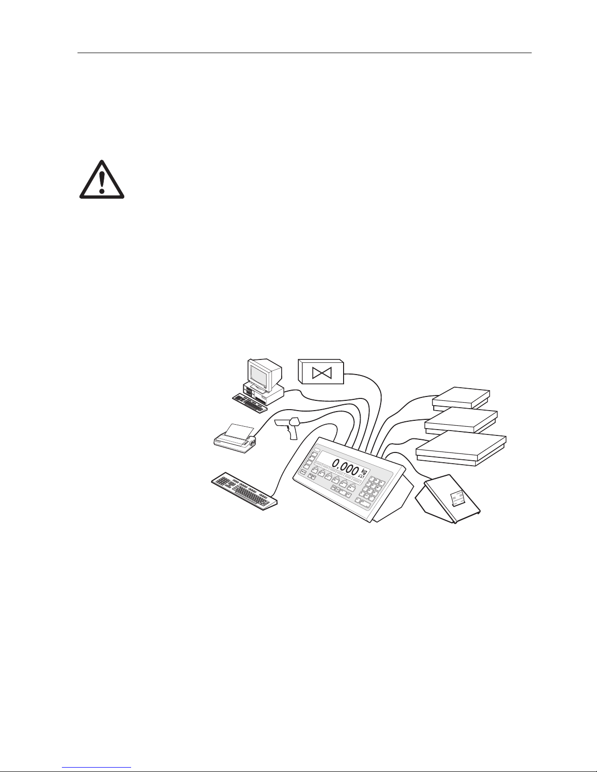
With the ID7-Base weighing terminal the following applications are possible:
• Multi-scale operation with up to 3 weighing platforms, including a weighing
platform with an analog signal output.
• Up to 6 data interfaces
– for printing,
– for data exchange with a computer,
– for connecting a barcode reader,
– for control, e.g. of valves or flaps,
– for connecting reference scales.
• Comfortable alphanumeric entry via an external keypad.
Page 6
Introduction and commissioning
4 Operating instructions and installation information 22004109D 04/10
ID7-Base
1.3 ID7-Base weighing terminal
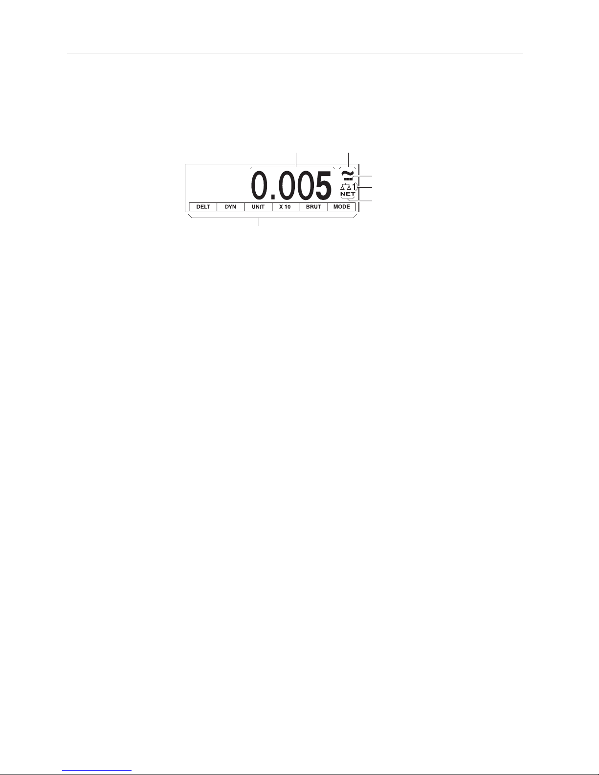
1.3.1 Display
1 Weight display BIG WEIGHT
®
with sign and decimal point
2 Stability monitor: lights up until the weighing platform has levelled out, then the
weight unit appears here
3 Range display for multi-range weighing platforms
4 Number of the weighing platform: shows the weighting platform just selected
5 NET symbol for marking net weight values
6 Assignment of the function keys
12
4
5
6
3
Page 7
Introduction and commissioning
Operating instructions and installation information 22004109D 04/10 5
ID7-Base
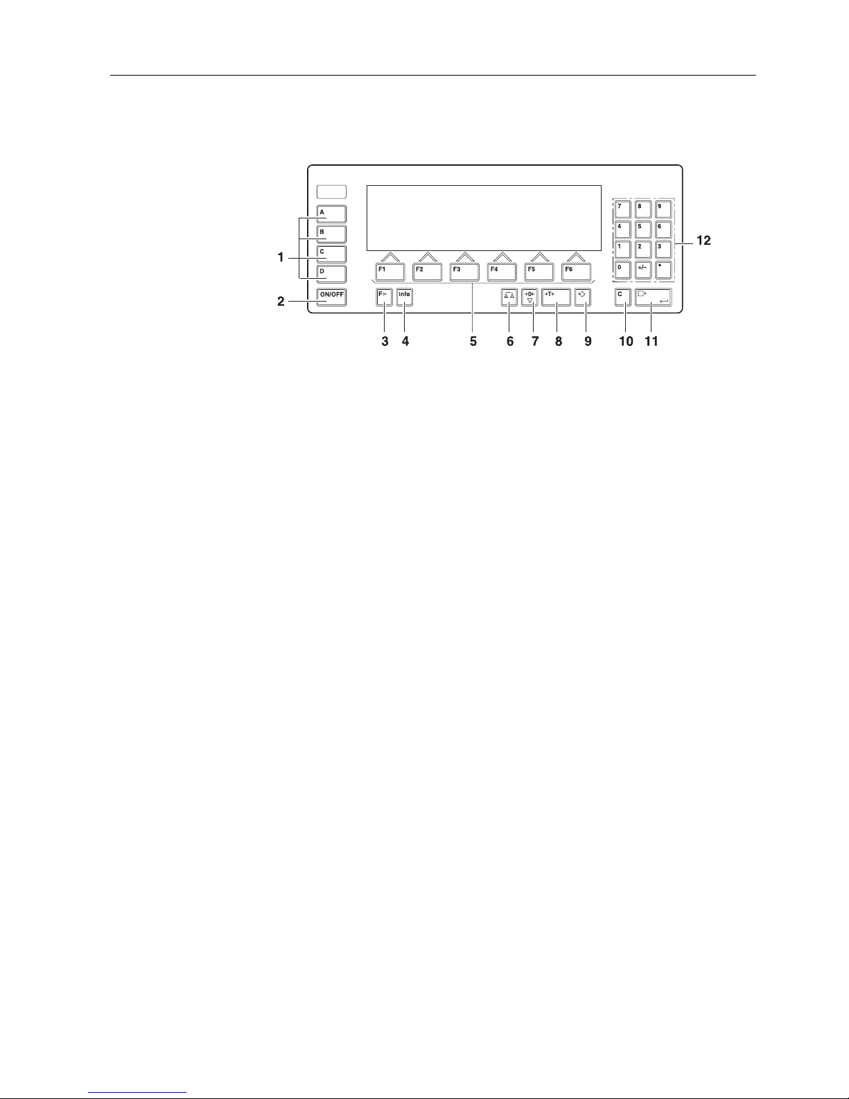
1.3.2 Keypad
1 CODE A ... CODE D keys – enter identification data
2 ON/OFF – On/Off key
3 FUNCTION CHANGE key – display additional functions
when entering weight values: switch over unit
4 INFO key – recall memory contents and system information
5 Function keys F1 … F6 – the current assignment is shown in the display above
the key
6 SCALE key – select scale
7 ZERO-SET key – set scale to zero, test scale
8 TARA key – tare scale
9 TARE SPECIFICATION key – enter known tare values numerically
10 CLEAR key – clear entries and values
11 ENTER key – accept and transfer data
12 Numeric keypad with decimal point and signs
Page 8
Introduction and commissioning
6 Operating instructions and installation information 22004109D 04/10
ID7-Base
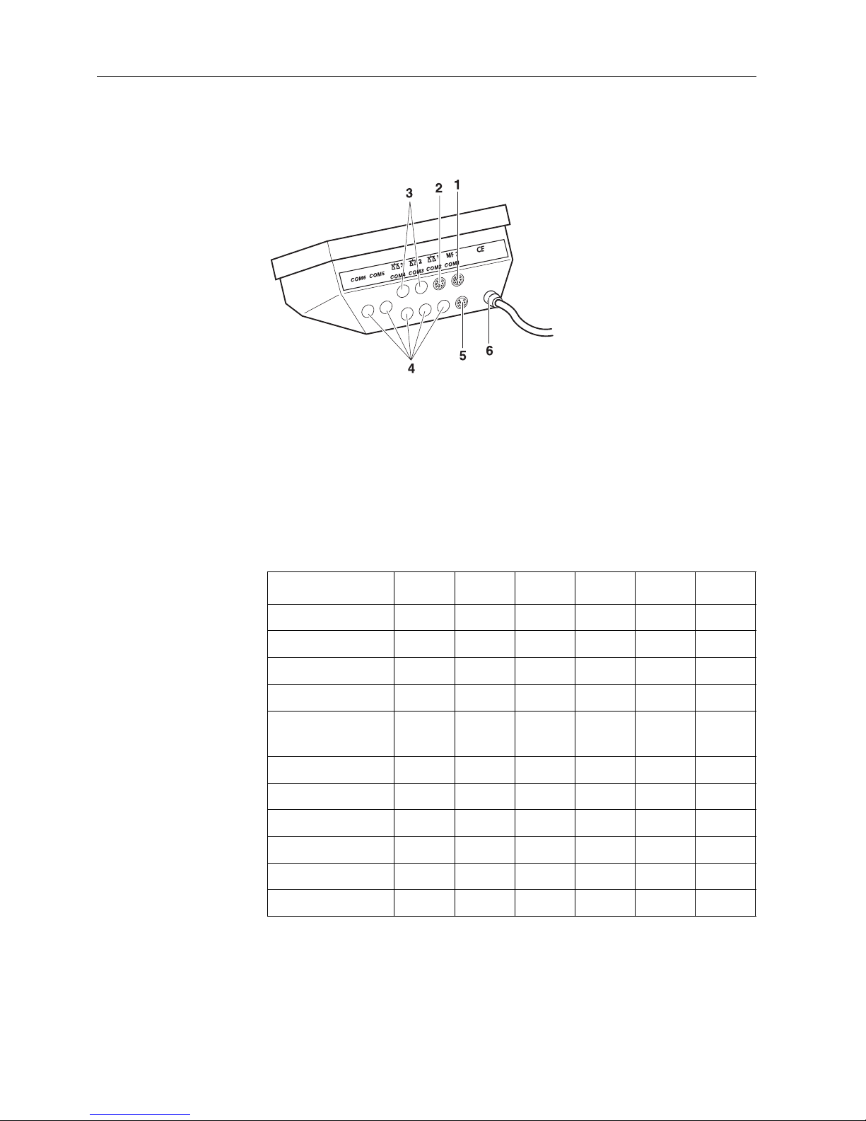
1.3.3 Connections
1 Connection for the external MFII keypad
2 Connection for weighing platform 1
3 Optional connections for weighing platforms 2 and 3
4 5 optional interface connections
5 Standard RS232 interface
6 Power supply
Possible assignments for serial interfaces
Interface COM1 COM2 COM3 COM4 COM5 COM6
CL20mA-ID7 –xxxxx
RS232-ID7 xxxxxx
RS422-ID7 ––––xx
RS485-ID7 ––––xx
RS485-ID7 with
relay box 8-ID7
––––xx
4 I/O-ID7 ––––xx
Analog Output-ID7 ––––xx
Alibi Memory-ID7–xxxxx
Ethernet-ID7–xxxxx
Profibus-DP-ID7–xxxxx
WLAN-ID7 –xxxxx
Page 9
Introduction and commissioning
Operating instructions and installation information 22004109D 04/10 7
ID7-Base
Notes
• COM1 is permanently equipped with the serial interface RS232-ID7 as standard.
• Only one Alibi Memory ID7 can be installed. It has no additional external
connection, and internally it occupies the space of a data port COM2 ... COM6.
Alibi Memory ID7 is installed as COM4 at the factory.
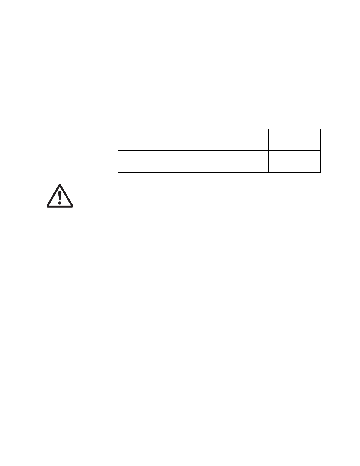
• A maximum of 4 cards Analog Scale-ID7, Ethernet-ID7, Profibus-DP-ID7, WLAN-ID7
or Alibi Memory-ID7 can be installed in the ID7-Base. The following combinations
are possible:
CAUTION
➜ Cover unused connection sockets with protective caps to protect the socket
contacts from moisture and dirt.
1.4 Commissioning
1.4.1 Connect weighing platforms of the series D, F, K, N, Spider ID and AWU3/6
1. Set up weighing platform, see installation instructions of weighing platform.
2. Route weighing platform cable to weighing terminal.
3. Plug in weighing platform connector on weighing terminal.
1.4.2 Connect scales of the series B, G, R and DigiTOL
Precision scales of the series B, G and R can be connected to the ID7-Base weighing
terminal with the LC-IDNet B or LC-IDNet R/G connection set.
To connect DigiTOL scales, the GD17 connection set is required.
1. Set up scale, see operating instructions of scale.
2. Connect appropriate connection set to scale.
3. Route cable of connection set to weighing terminal and plug in.
1.4.3 Commissioning with several weighing platforms
➜ To start up the ID7-Base weighing terminal with several weighing platforms,
please contact METTLER TOLEDO Service.
Analog Scale-ID7
Ethernet-ID7
or WLAN-ID7
Profibus-DP-ID7 Alibi Memory-ID7
211 –
1111
Page 10

Introduction and commissioning
8 Operating instructions and installation information 22004109D 04/10
ID7-Base
1.4.4 Connect ID7-Base to network
CAUTION
The ID7-Base weighing terminal only functions properly with mains voltages of
100 V to 240 V.
➜ Make sure that the mains voltage at the installation location lies within this
range.
➜ Make sure that the mains outlet is grounded and easily accessible.
Connecting
➜ Plug mains plug of ID7-Base into a mains outlet.
In the factory setting the display briefly shows METTLER TOLEDO ID7 and the
versions of the installed components; then the weight display appears.
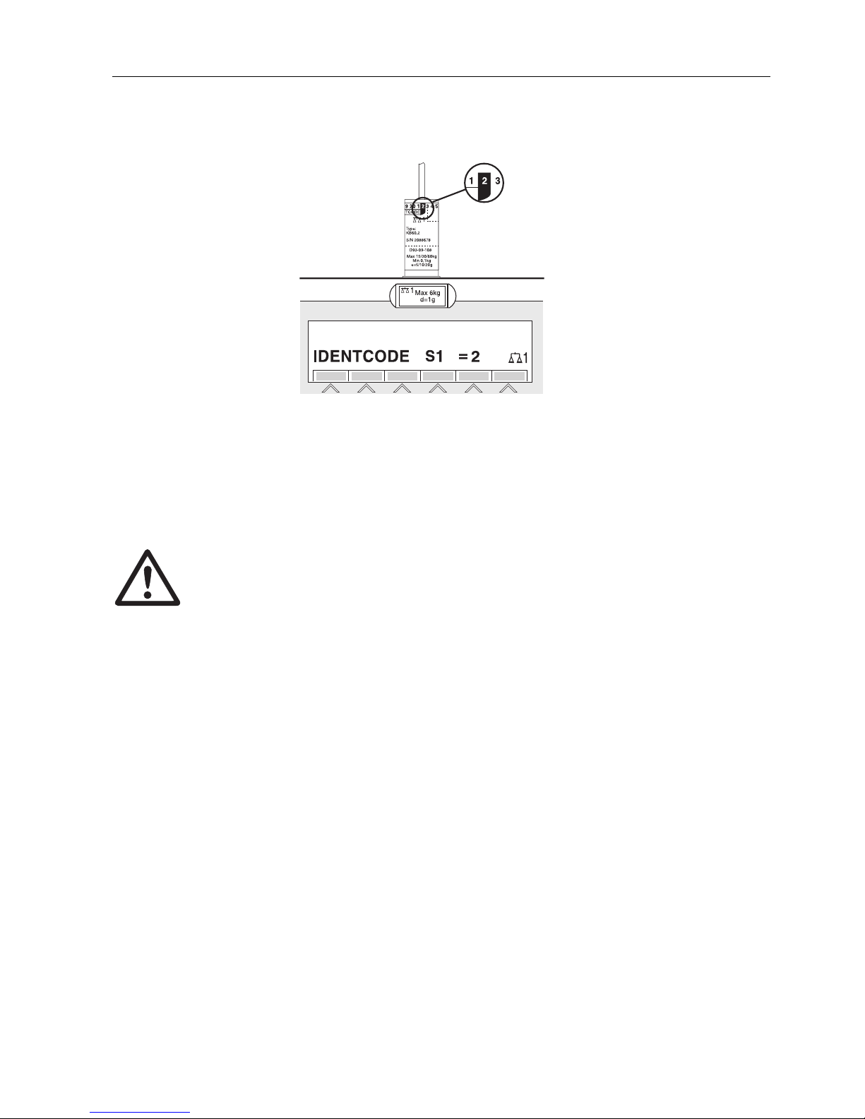
1.4.5 Marking and sealing of certified weighing platforms
ID code With the ID code it can be checked whether certified weighing platforms have been
tampered with since the last certification. The ID code can be displayed on the
terminal at any time, see section 3.10.
During certification the currently displayed ID code is recorded and sealed.
During each change to the configuration the displayed ID code increases. It then no
longer matches the sealed ID code; the certification is not longer valid.
Certification To mark and certify your weighing system, please contact METTLER TOLEDO Service
or your local board of weights and measures.
Check certification
1. Display ID code, see section 3.10; press ZERO-SET key until IDENTCODE = ...
is displayed.
No value is shown for noncertified weighing platforms, but instead:
IDENTCODE ===.
2. Compare ID code displayed with sealed ID code on ID card.
The certification of the weighing system is only valid when both values are
identical.
Page 11
Introduction and commissioning
Operating instructions and installation information 22004109D 04/10 9
ID7-Base
3. Press ZERO-SET key again.
The connected weighing platform is checked. The display shows CHECK SCALE
and after the test is completed SCALE IS OK.
Then the ID7-Base automatically returns to normal operation.
1.5 Cleaning
DANGER OF SHOCK
➜ Do not open ID7-Base weighing terminal to clean.
CAUTION
➜ Make sure that unused connection sockets are covered with protective caps to
protect the socket contacts from moisture and dirt.
➜ Do not use high-pressure cleaners.
Cleaning
➜ Wipe off ID7-Base weighing terminal with a commercially available glass or
plastic cleaner.
Page 12

Basic functions
10 Operating instructions and installation information 22004109D 04/10
ID7-Base
2 Basic functions
2.1 Switching on and off
Switch on from the standby mode
➜ Press 0N/OFF key.
The display shows a weight value based on the last tare value and zero point.
Switch on with restart
1. Relieve weighing platform.
2. Press ON/OFF key and hold down until METTLER TOLEDO ID7 (factory setting) or
text you have specified appears in display.
Then weight value 0.000 kg appears.
The weighing platform is restarted.
Note
The text which appears during switch-on with a restart is saved in the text
memory 20, see section 4.3.2.
Switch off
➜ Press ON/OFF key.
The display goes out and the ID7-Base weighing terminal is in the standby
mode. The zero point and tare value remain saved.
2.2 Setting to zero
Setting to zero corrects the influence of minor dirt on the load plate.
In the case of excessive dirt which cannot be compensated by setting to zero, the
display shows OUT OF RANGE.
Manual zero set
1. Relieve weighing platform.
2. Press ZERO-SET key.
The display shows 0.000 kg.
Automatic zero set
On certified weighing platforms the zero point of the weighing platform is automatically corrected when the weighing platform is relieved.
The automatic zero set can be switched off in the master mode on noncertified
weighing platforms.
Page 13

Basic functions
Operating instructions and installation information 22004109D 04/10 11
ID7-Base
2.3 Taring
2.3.1 Manual taring
1. Place empty container on scale.
2. Press TARE key.
The tare weight is saved and the weight display set to zero.
The display shows the NET symbol.
Notes
• When the weighing platform is relieved, the saved tare weight is displayed with a
negative sign.
• The weighing platform only saves one tare value.
2.3.2 Automatic taring
Prerequisite
AUTOTARA ON must be set in the master mode, see section 4.4.
➜ Place empty container on scale.
The container weight is automatically saved and the weight display set to zero.
The display shows the NET symbol.
Note
When the weighing platform is relieved, the saved tare weight is cleared.
2.3.3 Specify tare weight
Enter numerically 1. Press TARE SPECIFICATION key.
2. Enter tare weight (container weight) and confirm with ENTER.
When weighing platform is relieved, the entered tare weight is displayed with a
negative sign.
Note
With the FUNCTION CHANGE key you can select the weight unit for entering the tare
weight.
Correct entry ➜ Clear the entry character by character with the CLEAR key and repeat correctly.
Page 14

Basic functions
12 Operating instructions and installation information 22004109D 04/10
ID7-Base
Copy tare
constant
The ID7-Base has 999 tare memories for frequently used tare weights programmed
in the master mode.
1. Enter memory number: 1… 999.
2. Press TARE SPECIFICATION key.
The display shows the NET symbol and the net weight based on the recalled tare
weight.
2.3.4 Recall currently saved tare weight
The saved tare weight can be recalled at any time.
➜ Enter INFO, TARE SPECIFICATION key sequence.
The saved tare weight is displayed.
2.3.5 Clear tare weight
➜ Relieve weighing platform and tare.
– or –
➜ Specify tare weight 0.
– or –
➜ Enter TARE SPECIFICATION, CLEAR key sequence.
2.4 Weighing
Weighing without taring
➜ Lay weighing sample on weighing platform.
Gross weight (total weight) is displayed.
Weighing with taring
1. Place the empty container on the weighing platform and tare.
2. Pour in weighing sample.
The display shows the net weight and the NET symbol.
Weighing with tare specification
1. Place filled container on weighing platform.
The display shows the gross weight (total weight).
2. Specify tare weight or recall tare memory.
The display shows the net weight (container content) and the NET symbol.
Note
If a multi-range weighing platform is chosen, a display for the currently active range
appears above the scale symbol.
Page 15

Basic functions
Operating instructions and installation information 22004109D 04/10 13
ID7-Base
2.5 Switch over weighing platform
Up to 3 weighing platforms can be connected to the ID7-Base.
The weighing platform currently selected is shown on the terminal.
➜ Press SCALE key.
The next weighing platform is selected.
– or –
➜ Enter number of weighing platform and press SCALE key.
The desired weighing platform is selected.
Page 16
Additional functions
14 Operating instructions and installation information 22004109D 04/10
ID7-Base
3 Additional functions
The assignment of the 6 function keys of the ID7-Base weighing terminal differs
depending on the weighing task. The current assignment is shown above the function
keys.
With the FUNCTION CHANGE key it is possible to switch over to other function key
assignments.
Independent of the application software, the ID7-Base has the following additional
functions:
If at least one dynamic switching point is configured in the master mode (see page
51), the second row of function keys is given the following assignment:
3.1 Weighing with the DeltaTrac
The DeltaTrac is an analog display which makes it easier to read the weighing
results.
In the master mode you can select how the DeltaTrac is displayed for the various
weighing tasks FILLING, CLASSIFYING or CHECKWEIGHING.
Note
• With the DeltaTrac signals you can also control lamps, flaps or valves, see section
4.5.4.
DELT DYN UNIT X 10 GROSS MODE
Weighing
with the
DeltaTrac,
see 3.1
Dynamic
weighing,
see 3.2
Change
weight unit,
see 3.3
Increase resolution, see
3.4. This key
is not assigned when
the control
mode is continually
switched on.
Display
gross weight,
see 3.5
Activate
master mode,
see
Chapter 4
MULT-TARE ADD-TARE SANDWICH-T
Multiplicative tare function,
see 3.7
Additive tare function, see 3.8 Sandwich tare, see 3.9
SETP MUL-T ADD-T SW-T
Set dynamic
set points,
see 3.6
Multiplicative
tare function,
see 3.7
Additive tare
function,
see 3.8
Sandwich
tare, see 3.9
Page 17
Additional functions
Operating instructions and installation information 22004109D 04/10 15
ID7-Base
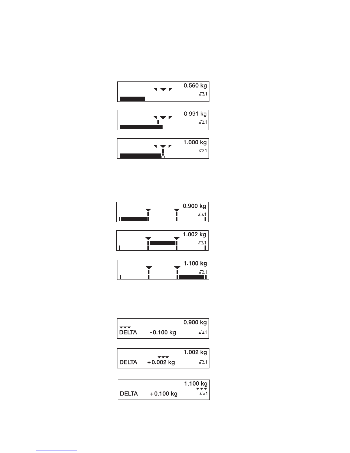
Application
FILLING
For weighing-in to a target weight with tolerance monitoring.
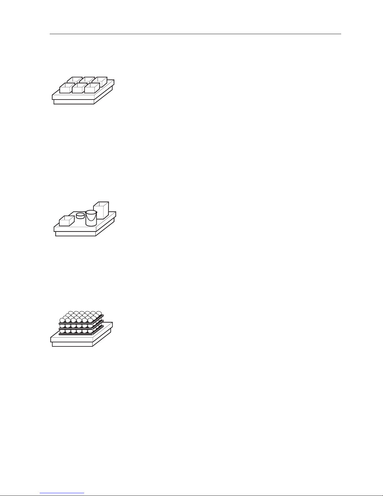
Application
CLASSIFYING
To evaluate test samples as OKAY, TOO LIGHT or TOO HEAVY, based on a target
weight and specified +/– tolerances.
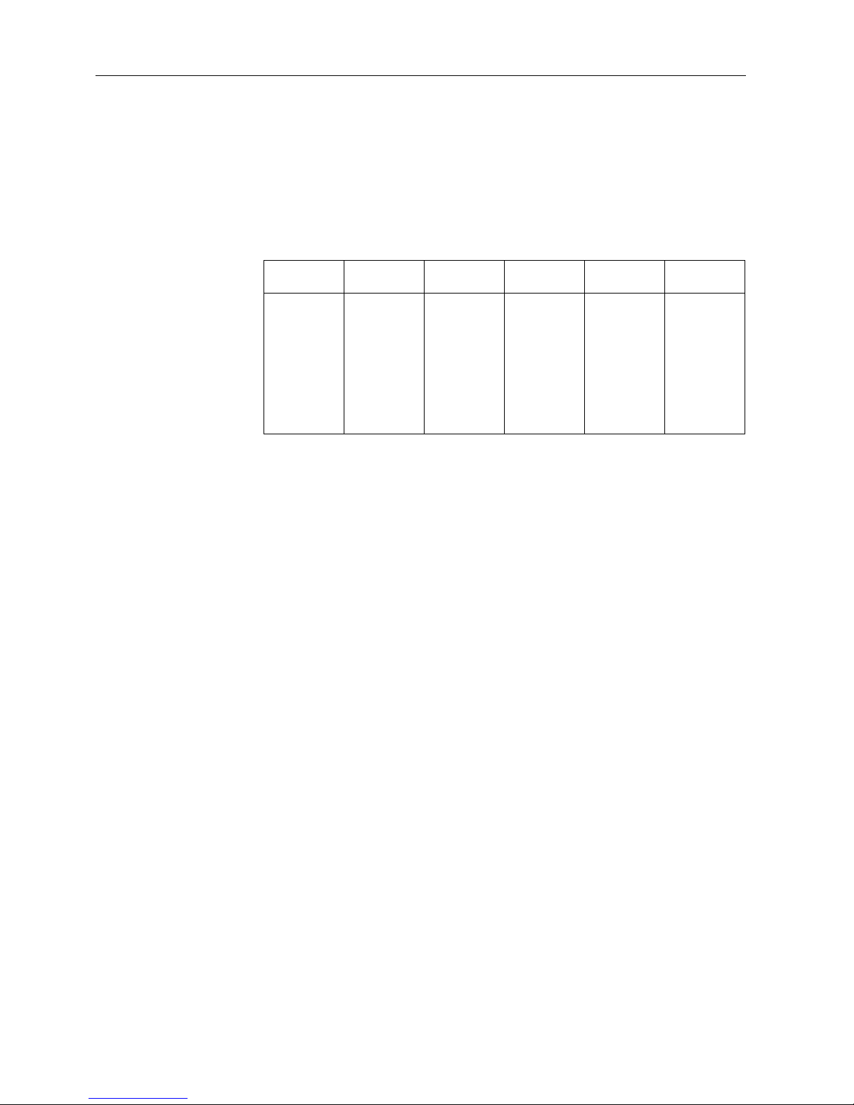
Application
CHECKWEIGHING
For determining the difference between the target and actual weight.
Example: Target weight = 1.000 kg, tolerance = 1 %
Target weight not reached yet
Weight within the tolerance
Target weight reached exactly
Example: Target weight = 1.000 kg, tolerance = 1 %
TOO LIGHT
Weight below the tolerance
OKAY
Weight within the tolerance
TOO HEAVY
Weight above the tolerance
Example: Target weight = 1.000 kg, tolerance = 1 %
Weight below the tolerance
Difference: –0.100 kg
Weight within the tolerance
Difference: +0.002 kg
Weight above the tolerance
Difference: +0.100 kg
Page 18

Additional functions
16 Operating instructions and installation information 22004109D 04/10
ID7-Base
3.1.1 Preset DeltaTrac target values
Enter numerically 1. Press DELT key.
2. Enter target weight and confirm with ENTER.
3. Enter tolerance in % of target weight and confirm with ENTER.
Note
With the FUNCTION CHANGE key you can select the weight unit for entering the
DeltaTrac target values.
Correct entry ➜ With the CLEAR key the entry is corrected character by character.
Copy constants The ID7-Base weighing terminal has 999 DeltaTrac memories for frequently used
target values and tolerances, which are programmed in the master mode.
1. Enter number of DeltaTrac memory: 1 … 999.
2. Press DELT key.
Reference sample 1. Press DELT key.
2. Lay sample on weighing platform and confirm with SCALE key.
3. Only for FILLING and CLASSIFYING: Enter tolerance and confirm with ENTER.
4. Remove sample from weighing platform.
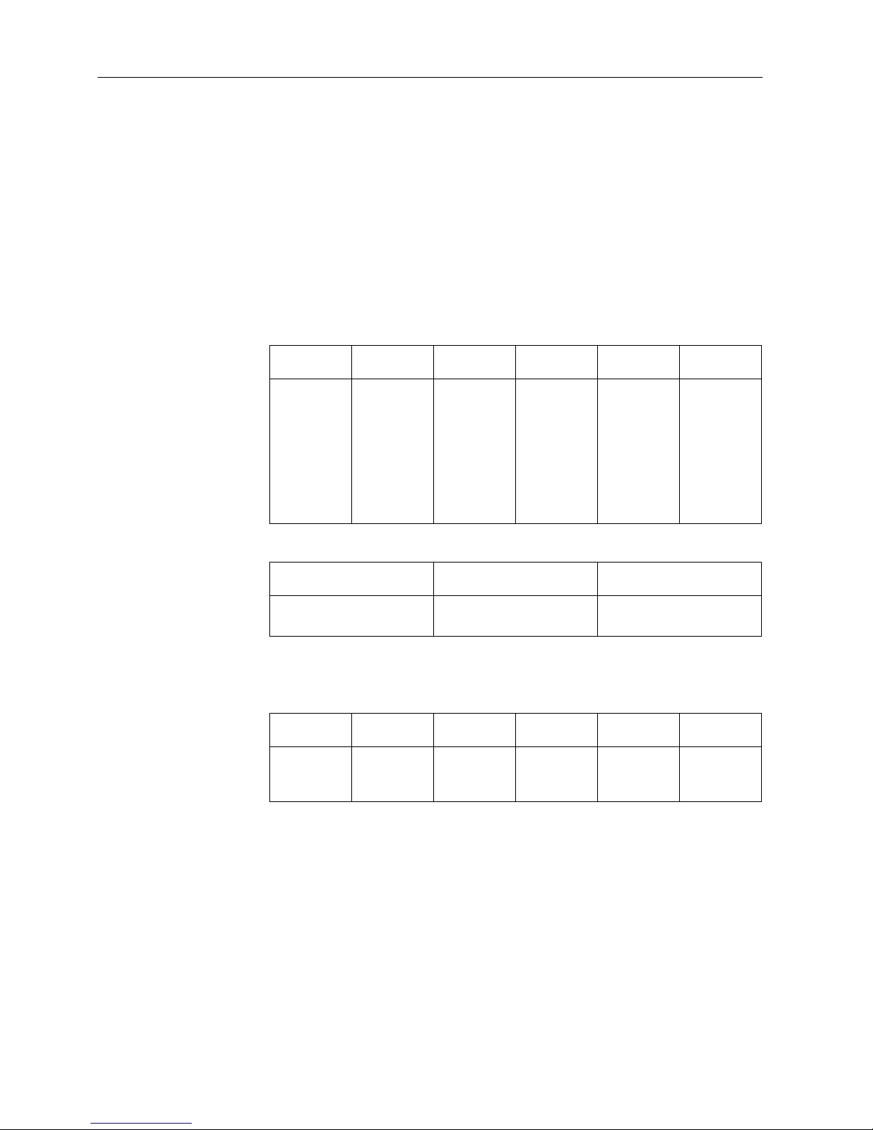
Limits Minimum target value 10 Digit, can be adjusted in mastermode, see section 4.3
Maximum target value configured maximum load
Minimum tolerance 1 Digit
Maximum tolerance 10 % for the applications FILLING, CHECKWEIGHING
50 % for the application CLASSIFYING
Note
If the limits are not observed, a message appears in the display, e.g. MIN-DEL = ...,
for too small a target value.
Clear DeltaTrac target
value
➜ Press DELT CLEAR key sequence.
DELTA CLEARED appears briefly in the display, then the weight is shown.
Page 19

Additional functions
Operating instructions and installation information 22004109D 04/10 17
ID7-Base
3.2 Dynamic weighing
With the dynamic weighing function you can weigh restless weighing samples, e.g.
live animals. To do this, specify the number of weighing cycles for which the mean
weight value is to be taken.
1. Set container on the weighing platform.
2. Tare weighing platform.
3. Place weighing sample in container.
4. Press DYN key and enter number of weighing cycles.
Possible values: 1 … 255.
5. Start dynamic weighing with ENTER key.
6. After cycle time has expired, center line of display shows:
RESULT x.xxxx kg.
This display is retained until the next weighing is started or until it is cleared.
Delete result ➜ Press CLEAR key.
Notes
• Dynamic weighing results are automatically printed when AUTO PRINT is set in the
master mode, see section 4.3.2.
• During dynamic weighing it is not possible to display the weight value BIG
WEIGHT DISPLAY, which fills the entire display.
• Dynamic weighing can also be started with the interface command AW016..., see
section 6.2.
3.3 Change weight unit
If an additional, second weight unit is configured in the master mode, it is possible to
switch back and forth between the two weight units.
➜ Press UNIT key.
The weight value is shown in the second unit.
Note
Possible second weight units are: g, kg, lb, oz, ozt, dwt.
Page 20

Additional functions
18 Operating instructions and installation information 22004109D 04/10
ID7-Base
3.4 Working in a higher resolution
Depending on the setting of the master mode block CONTROL MODE (see page 32),
the weight value can be displayed in a higher resolution continuously or when called.
Weight values in a higher resolution are marked with a *.
Displaying weight values in higher resolution
➜ Press X 10 key.
The weight value is displayed in at least a 10x higher resolution.
The higher resolution is displayed until the X 10 key is pressed again.
Note
With certified weighing platforms, the weight value only appears in a higher
resolution as long as the X 10 key is pressed.
3.5 Display gross weight
The gross weight can only be displayed when a tare weight has been saved.
➜ Press GROSS key and hold down.
The gross weight is displayed.
3.6 Specifying dynamic set points
Conditions
• 4 I/O-ID7 interface or 8-ID7 relay box connected.
• SETPOINT MODE ON and at least one dynamic set point is configured in the
master mode.
Use If the specified set point values are exceeded or dropped below, digital outputs are
set, e.g. for controlling lamps, flaps, valves etc.
Dynamic set points can be set for each weighing procedure individually.
The set points are retained until they are overwritten with a new value or deleted.
Specifying set points
1. Press the SETP key; the entry prompt for the first dynamic set point appears.
2. Enter the desired weight value and confirm with ENTER.
3. If additional dynamic set points are configured, the entry prompt appears for the
next dynamic set point.
4. Enter the desired weight value and confirm with ENTER.
5. Repeat the procedure until all set points have been entered.
Deleting set points
➜ Press the SETP key and delete the value with the CLEAR key.
Page 21
Additional functions
Operating instructions and installation information 22004109D 04/10 19
ID7-Base
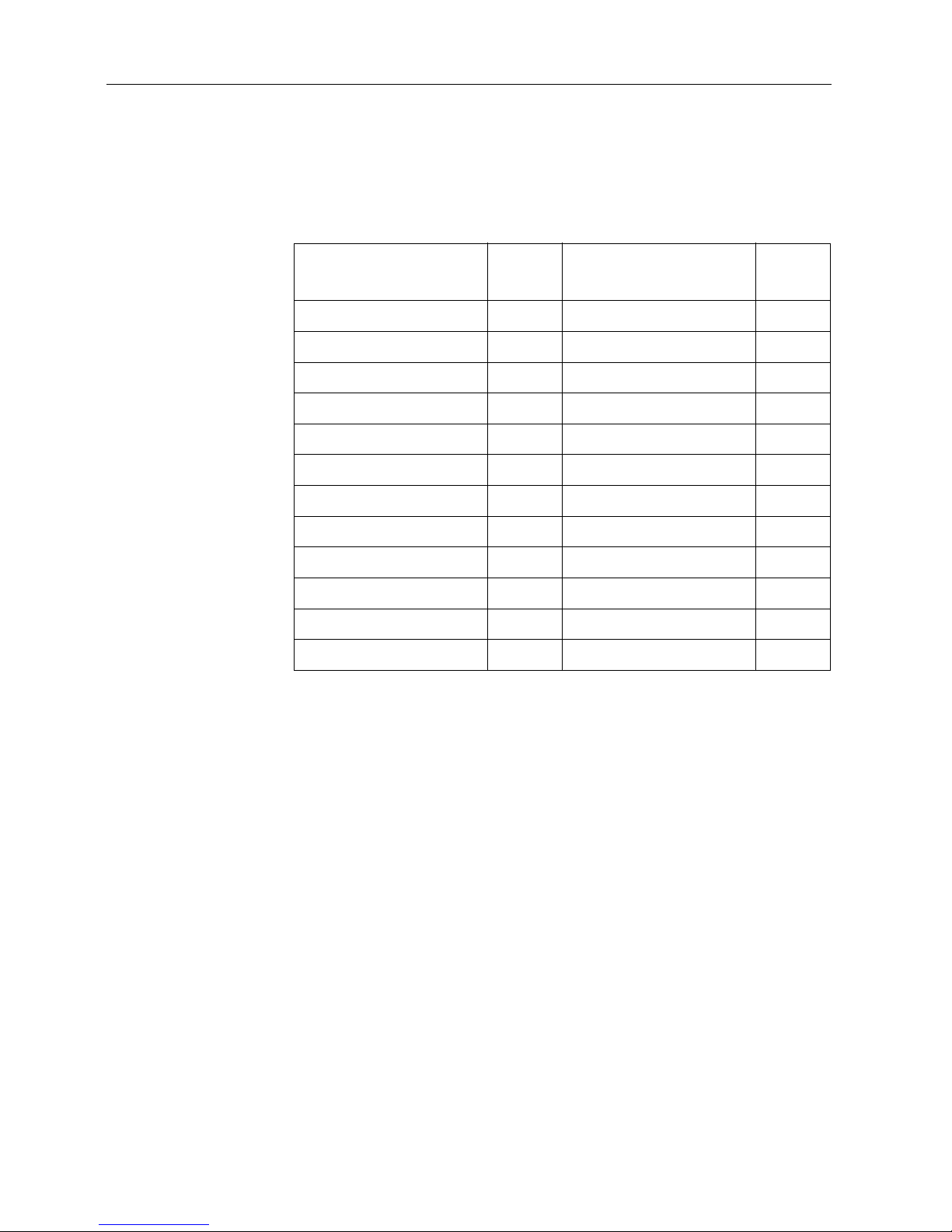
3.7 Multiplicative tare function
The multiplicative tare function is particularly suitable when pallets with identical
containers are filled. If the number of containers and tare of the individual container
are known, the ID7-Base weighing terminal calculates the total tare.
1. Press MULT TARE key.
2. Enter known tare weight of individual container and confirm with ENTER.
3. Enter number of containers and confirm with ENTER.
When the weighing platform is relieved, the total tare value is shown in the
display with a negative sign.
Note
With the FUNCTION CHANGE key you can select the weight unit for entering the tare
weight.
3.8 Additive tare function
With the additive tare function you can subtract the tare of additional containers with
a know tare weight for related weighings, e.g. if containers with different weights are
filled on one pallet.
1. Place container on scale and press ADD TARE key.
2. Enter known tare weight and confirm with ENTER.
The total net weight appears in the weight display.
Note
With the FUNCTION CHANGE key you can select the weight unit for entering the tare
weight.
3.9 Sandwich tare
With the sandwich tare function you can detect additional tare weights for related
weighings without loosing the total gross and total net.
Example
In production or shipping boxes are laid between individual layers in the transport
container. The weight of these boxes can be subtracted with this function.
1. Press SANDWICH-T key.
2. Place sandwich tare, e.g. box, on scale and confirm with ENTER.
The net weight is retained.
Page 22

Additional functions
20 Operating instructions and installation information 22004109D 04/10
ID7-Base
3.10 Display ID code and test weighing platform
Each time the weighing platform configuration is changed the ID code counter is
increased by 1. On certified weighing platforms the displayed ID code must match
the ID code on the ID code sticker, otherwise the calibration is no longer valid.
Display ID code
➜ Press ZERO-SET key and hold until IDENTCODE = ... appears in the display and
press again.
Test weighing platform
➜ Press ZERO-SET key again.
The connected weighing platform is checked. The display shows CHECK SCALE
and then SCALE IS OK after completing the test.
Note
If weighing platform is defective, display shows SCALE ERROR.
3.11 Identifications
The ID7-Base weighing terminal is equipped with 4 identification data memories for
storing identification data Code A … Code D.
The memories have a name, e.g. Article No., and a content which identifies the
current weighing, e.g. 1234567.
The memories are named in the master mode, and the names can be noted on the
keyboard. When the CODE keys are pressed, the name appears in the display.
Identification data Code A … Code D can be entered or recalled for each weighing
and are printed immediately.
3.11.1 Enter identification
An identification may contain a maximum of 20 characters.
Enter
numerical identification
1. Press one of the keys CODE A … CODE D.
2. Enter identification data Code A … Code D via the numeric keypad and confirm
with ENTER.
Page 23

Additional functions
Operating instructions and installation information 22004109D 04/10 21
ID7-Base
Enter
alphanumeric
identification
1. Press one of the keys CODE A … CODE D.
The functions keys are given the following assignment:
2. Select desired group of letters, e. g. press KLMNO key.
3. Select desired letter.
The display changes again to the above selection.
4. Repeat entry in steps 2 and 3 for additional characters.
Note
Letters and numbers can be combined as desired.
Recall fixed text
memory
The ID7-Base weighing terminal is equipped with 999 memories for fixed texts which
can be programmed in the master mode and used as identifications.
1. Enter memory number: 1 ... 999.
2. Press a key CODE A … CODE D.
The saved fixed text is now assigned to the selected identification Code A …
Code D.
Other entry possibilities Identifications can also be entered with a barcode reader, see section 3.14, or with
an external keypad, see section 3.15.
3.11.2 Clear identifications
➜ Press desired key CODE A … CODE D and clear memory content with CLEAR key.
ABCDE FGHIJ KLMNO PQRST UVWXY Z/-()
Selection of
letters A to E
Selection of
letters F to J
Selection of
letters K to O
Selection of
letters P to T
Selection of
letters U to Y
Selection of
letter Z and
special
characters
Page 24
Additional functions
22 Operating instructions and installation information 22004109D 04/10
ID7-Base
3.12 Recall information
On the ID7-Base weighing terminal memory contents and system information can be
recalled.
1. Press INFO key.
Then the following function key assignment appears:
2. Select desired information.
The information is displayed for the set DISPLAY DURATION, then the ID7-Base
changes to the weighing mode again.
Notes
• When several values are displayed, the ID7-Base automatically changes to the
next value after the set DISPLAY DURATION.
• With the CLEAR key it is possible to switch to the next value or back to the
weighing mode.
• When the GA46 printer is connected, the version numbers of the installed software
modules are automatically printed.
3.12.1 Recall memory
1. Press INFO key.
2. Enter number of memory and press DELT, TARA or TEXT key depending on
desired memory.
Recall name of CODE A … CODE D keys
1. Press INFO key.
2. Press one of the keys CODE A … CODE D.
The display shows the current Code.
DELT TARE TEXT ALIBI DATE VERS
Display
DeltaTrac
values
Display tare
weight
Display fixed
texts and
name of keys
CODE A …
CODE D
Recall content
of alibi
memory, see
section 2.1.
This selection
only appears
when Alibi
Memory-ID7
is installed.
Display date
and time
Display
version
numbers of
installed
software
modules
Page 25

Additional functions
Operating instructions and installation information 22004109D 04/10 23
ID7-Base
3.13 Print or transfer data
If a printer or computer is connected, weighing results can be printed out or
transferred to the computer.
In the master mode you can set the following for this purpose:
• Data to be printed or transferred,
• Manual or automatic data transfer,
• Key which triggers printing or data transfer.
Factory setting
• Manual triggering with the ENTER key.
• The content of the display is transferred or printed.
3.14 Enter values with barcode reader
If you have connected a barcode reader to the ID7-Base weighing terminal, you can
make all required entries, such as identifications or target specifications, easily with
the barcode reader.
3.14.1 Read in any desired entries with the barcode reader
Example Read in identification Code A
1. Press CODE A key; the ID7-Base expects the entry of Code A.
2. Enter identification Code A with the barcode reader.
The identification read in appears in the display.
3. Confirm barcode entry with ENTER.
3.14.2 Read in a frequently used entry directly with the barcode reader
If your working procedure repeatedly requires the same entry, you can configure the
barcode reader in the master mode (see section 4.5.3) so that no additional keys
need to be pressed on the ID7-Base terminal for barcode entry.
Example Barcodes are automatically read in as Code A
If the working procedure requires the entry of Code A:
➜ Enter identification Code A with barcode reader.
The information read in appears in the display and is automatically processed by
ID7-Base as Code A.
Page 26
Additional functions
24 Operating instructions and installation information 22004109D 04/10
ID7-Base
3.15 Working with external keypad
In addition to the alpha and numerical keys, the following additional scale functions
can also be operated with the external AK-MFII keypad.
Note
The language of your external keyboard can be set in the master mode block LAYOUT
EXT. KEYBOARD, see page 30.
Function for ID7-Base
External
keypad
Function for ID7-Base
External
keypad
Function key F1 F1 CODE A key Shift F1
Function key F2 F2 CODE B key Shift F2
Function key F3 F3 CODE C key Shift F3
Function key F4 F4 CODE D key Shift F4
Function key F5 F5
Function key F6 F6
FUNCTION CHANGE key F7
INFO key F8
SCALE key F9 SCALE key Shift F9
ZERO-SET key F10 ZERO-SET key Shift F10
TARE key F11 TARE key Shift F11
TARE SPECIFICATION key F12 TARE SPECIFICATION key Shift F12
Page 27

Additional functions
Operating instructions and installation information 22004109D 04/10 25
ID7-Base
3.16 Working with a second display
An ID1 Plus, ID3s or another ID7-... weighing terminal can be connected to the
ID7-Base weighing terminal as a second display.
Conditions
• Interface CL 20mA-ID7 installed in passive operating mode (factory setting).
• AUTO-DIR setting selected in mastermode (see page 41).
• Weighing terminal is connected as second display with cable 00 504 511.
Operation possibilities on second display
The following functions are also possible on the second display:
• Set to zero
•Taring
ID7-... as second display
With ID7-... as a second display, the weight value fills the entire display (BIG
WEIGHT DISPLAY ON).
Page 28
Settings in the master mode
26 Operating instructions and installation information 22004109D 04/10
ID7-Base
4 Settings in the master mode
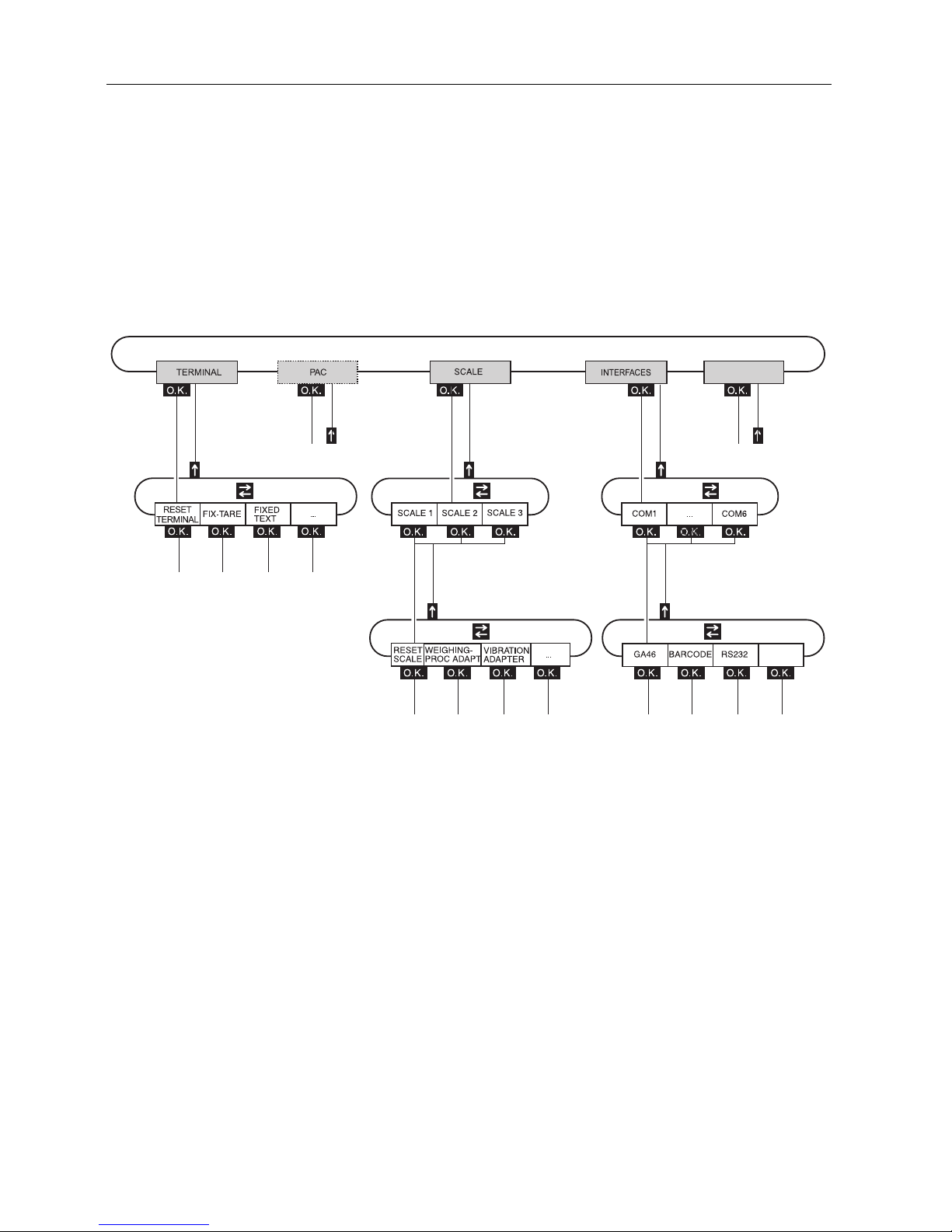
4.1 Overview of the master mode
In the master mode you adapt the ID7-Base weighing terminal to meet your needs.
Depending on the configuration, the master mode is divided into 4 or 5 master mode
blocks, which are in turn divided into further blocks.
TERMINAL For system settings, such as entering the date and time or loading permanent texts,
see section 4.3.2.
PAC To set application-specific parameters.
This block does not appear with ID7-Base.
SCALE To select one of the connected weighing platforms. For each selected weighing
platform the parameters are then set which concern the weight value, e. g. stability
detector, unit, etc., see section 4.4.
INTERFACES To select an interface. The communication parameters are then set for each interface,
see section 4.5.
SERVICE For configuring the weighing platform(s). On IDNet weighing platforms only for
METTLER TOLEDO service technicians.
SERVICE
Page 29
Settings in the master mode
Operating instructions and installation information 22004109D 04/10 27
ID7-Base
4.2 Operating the master mode
4.2.1 Enter the master mode
1. Press MODE key.
If the current function key assignment does not contain MODE, change to the
assignment with MODE by repeatedly pressing the FUNCTION CHANGE key.
2. Enter personal code if configured.
The display shows the first master mode block TERMINAL.
4.2.2 Assignment of function keys in the master mode
In the master mode the function keys are assigned as follows:
➜ Select the function by pressing the function key.
Example ➜ Press the END key to exit the master mode and return to the normal mode.
When the function keys are otherwise allocated
➜ Press the key FUNCTION CHANGE until the function keys allocation displayed
above appears.
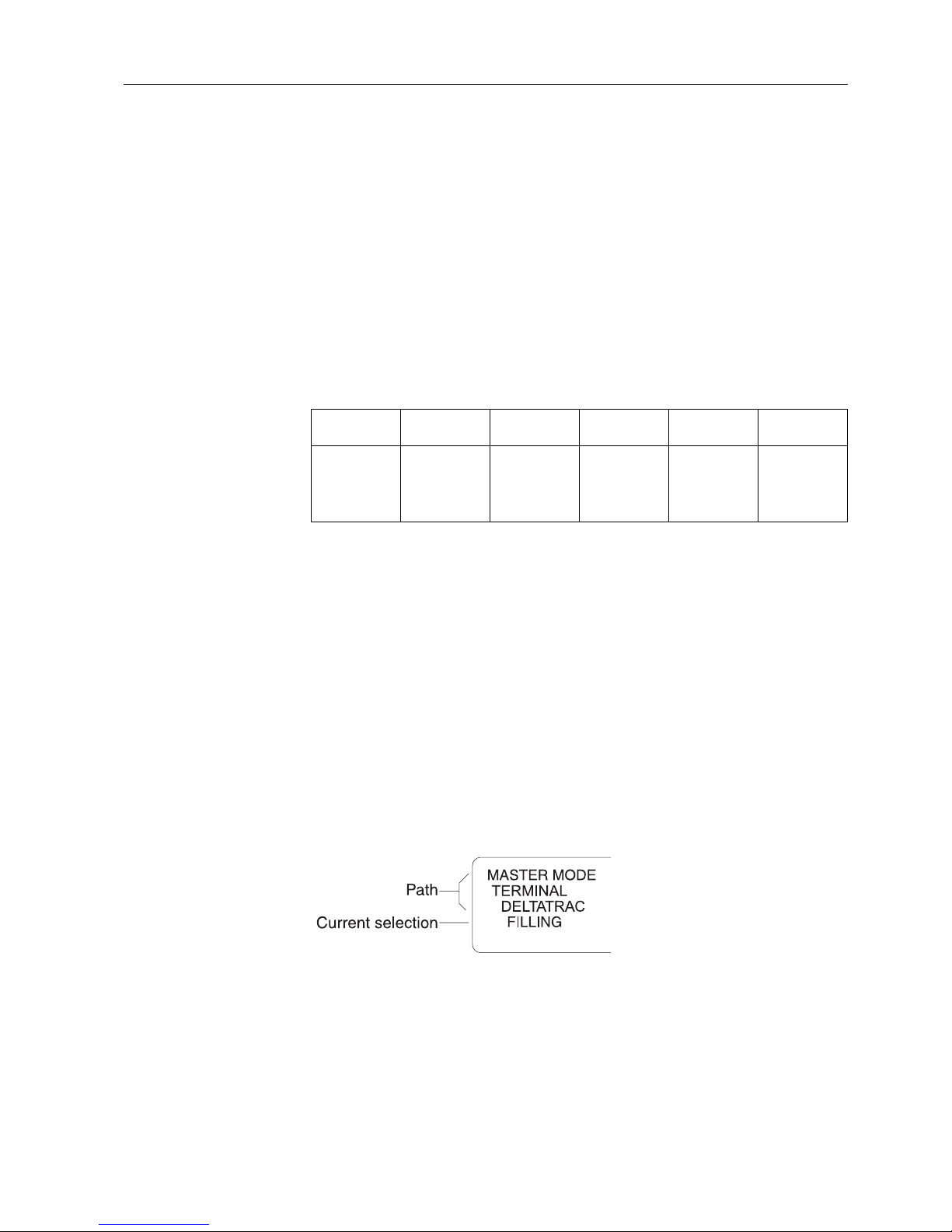
4.2.3 Orientation in the master mode
For improved orientation the display shows the last steps in the path of the current
master mode block.
Example The upper 3 lines of the display show the following path for selecting the DeltaTrac
application FILLING:
4.2.4 Entries in the master mode
The following basic rules apply to entries made in the master mode:
• Confirm (alpha)numeric entries with ENTER.
• Alphanumeric entries with the ID7-Base: see section 3.11.
• To accept the displayed value: Press ENTER key.
←→ ↑
END OK
Change to
previous
block within a
level
Change to next
block within a
level
Exit level and
return to
higher-level
block
Exit the
master mode
and return to
normal mode
Recall lowerlevel block or
confirm
selection
Page 30
Settings in the master mode
28 Operating instructions and installation information 22004109D 04/10
ID7-Base
4.2.5 Emergency entrance into the master mode
If a personal code has been assigned for entering the master mode and you have
forgotten your code, you can still enter the master mode:
➜ Enter the character sequence C, L, E, A, R as your personal code.
4.3 TERMINAL master mode block
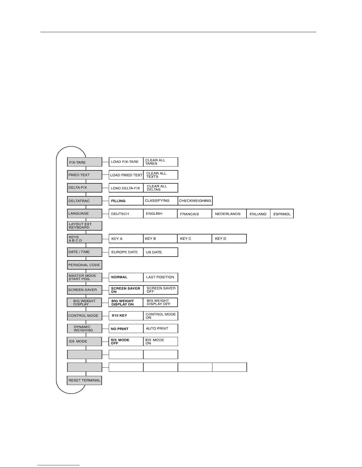
4.3.1 Overview of the TERMINAL master mode block
In the TERMINAL master mode block you enter the following system settings:
Legend • Blocks highlighted in grey are described in detail in the following.
• Factory settings are printed in bold print.
ERROR
MESSAGES
INFO
MESSAGES
CODE A
DISPLAY
DURATION
ENTRY PROMPT
CODE B
CODE C CODE D
Page 31

Settings in the master mode
Operating instructions and installation information 22004109D 04/10 29
ID7-Base
4.3.2 Settings in the TERMINAL master mode block
FIX-TARE Save tare values protected against power failure to tare memories
LOAD FIX-TARE 1. Enter memory number of FIX-TARE NO.: 1 … 999.
2. Enter tare weight for the selected memory in the displayed unit.
3. To load additional fixed tare values, repeat the first two steps.
4. End entry: Confirm FIX-TARE NO. without entry with ENTER.
CLEAR ALL TARES Delete all tare memories.
FIXED TEXT Save texts protected against power failure to text memories
These texts can be assigned, for example as identifications, or also output during
printing.
LOAD FIXED TEXT 1. Enter memory number of FIXED TEXT NO.: 1 … 999.
2. Enter text for the selected memory: max. of 20 characters.
3. To load additional fixed texts, repeat the first two steps.
4. End entry: Confirm FIXED TEXT NO. without entry with ENTER.
CLEAR ALL TEXTS Delete all text memories.
Comment Fixed Text No. 20 is displayed during switch-on with a restart, see section 2.1.
DELTA-FIX Save target weight/tolerance combinations in DeltaTrac memory
LOAD DELTA-FIX 1. Enter memory number of DELTA-FIX No.: 1 … 999.
2. Enter target weight TARG in the displayed unit.
3. Enter tolerance TOL in %.
4. To enter additional Delta-Fix, repeat the first three steps.
5. End entry: Confirm memory number without entry with ENTER.
CLEAR ALL DELTA Delete all DeltaTrac memories.
Page 32

Settings in the master mode
30 Operating instructions and installation information 22004109D 04/10
ID7-Base
DELTATRAC Set DeltaTrac application
TYPE Select DeltaTrac application
FILLING Weigh in target weight within a tolerance range (factory setting)
CLASSIFYING Evaluate the test samples as good, too light or too heavy based on the target weight
and tolerance
CHECKWEIGHING Determine difference between target and actual weight
AUTO PRINT WITHIN
TOL
Automatic printout when actual weight lies within the specified tolerance
PRINT ONLY WITHIN
TOL
Printout only when actual value lies within the specified tolerance
MIN. DELTA Specify minimum target weight, adjustable from 10 ... 100 d, factory setting: 40 d
LANGUAGE Select dialog language
Possible settings: German, English, French, Dutch, Italian, Spanish
LAYOUT EXT.
KEYBOARD
Select keyboard layout of connected external keyboard
Possible setting: Germany, England, France, Holland, Italy, Spain, Scandinavia,
Russia, Poland, Belgium, Switzerland, Slovakia, Czech Republic, Latin America,
Canada, ...
Page 33

Settings in the master mode
Operating instructions and installation information 22004109D 04/10 31
ID7-Base
KEYS A B C D Name identification keys CODE A … CODE D
KEY A Identifikation data CODE A
TEXT Factory setting: ARTICLE NO.
DATA LENGTH Max. 30 characters possible, factory setting: 20 characters
KEY B Identifikation data CODE B
TEXT Factory setting: ORDER NO.
DATA LENGTH Max. 30 characters possible, factory setting: 20 characters
KEY C Identifikation data CODE C
TEXT Factory setting: CODE NO.
DATA LENGTH Max. 30 characters possible, factory setting: 20 characters
KEY D Identifikation data CODE D
TEXT Factory setting: DOCUMENT NO.
DATA LENGTH Max. 30 characters possible, factory setting: 20 characters
DATE / TIME Enter date and time
TYPE
EUROPE Select European notation:
Day.Month.Year / (24) Hours.Minutes.Seconds
US Select American notation:
Month.Day.Year / (12) Hours.Minutes.Seconds AM/PM
DATE Enter date according to the type selected
TIME Enter time according to the type selected
Comments • Enter single-place numbers with a preceding zero.
• Change over between AM and PM: Press FUNCTION CHANGE key.
• Date and time can be printed out.
• The clock continues to run after the terminal is switched off.
PERSONAL CODE Load or delete code for entering the master mode
CODE Enter code with a maximum of 8 alphanumeric characters.
Comment If no code is entered, access to the master mode is unrestricted.
Page 34

Settings in the master mode
32 Operating instructions and installation information 22004109D 04/10
ID7-Base
MASTER MODE START
POS.
Select start position for entering the master mode
NORMAL Selection of the master mode blocks always begins with the TERMINAL block
(factory setting).
LAST POSITION When entering the master mode, the last block edited is displayed immediately.
SCREEN SAVER Switch screen saver on or off
WAITING TIME Enter time until screen saver is activated.
Possible values: 1 ... 99 minutes
Comment To hold all display elements at the same luminosity, we recommend not switching
off the screen saver.
BIG WEIGHT DISPLAY Switch full-display indication of the weight on or off
Factory setting: BIG WEIGHT DISPLAY ON
CONTROL MODE Adjust control mode
X10 KEY Activation of control mode with X10 key (factory setting).
CONTROL MODE ON This setting is only possible with non-certified scales.
The weighing terminal always operates with the higher resolution.
DYNAMIC WEIGHING Set printing during dynamic weighing
NO PRINT Results during dynamic weighing are not automatically printed out (factory setting).
AUTO PRINT Each result during dynamic weighing is automatically printed.
Dynamic weights are marked with "Result:" on the printout.
Page 35

Settings in the master mode
Operating instructions and installation information 22004109D 04/10 33
ID7-Base
ID5 MODE Deactivating or activating downward compatibility with ID5
If ID5 MODE ON is selected, the ID7-Base is operated with downward compatibility
to the ID5.
Affected settings
Text length of identification data 18 characters
Text length for keys CODE A ... D max. 18 characters
Date/time dd/mm/yy, hh-mm-ss
Barcode print command P$#1EAN13
P$#2Code 39
P$#3EAN13
Factory setting: ID5 MODE OFF
DISPLAY DURATION Set display duration for messages
ERROR MESSAGES Set display duration for error messages; factory setting: 2 seconds
INFO MESSAGES Set display duration for informational messages; factory setting: 3 seconds
ENTRY PROMPT Activating/deactivating entry prompt for Code A to D
CODE A
...
CODE D
If ENTRY PROMPT CODE X ON is selected, an item cannot be weighed until the
relevant code is entered.
Other settings:
REENTER The code must be entered again
REPEAT The last entry is suggested again
Factory setting: Entry prompt deactivated for all codes
Note The entry prompt is activated by pressing the following keys:
ENTER with ID7-Base
START with ID7-Dos
PLUS or CONTAINER with ID7-Form
Page 36

Settings in the master mode
34 Operating instructions and installation information 22004109D 04/10
ID7-Base
RESET TERMINAL Reset all terminal functions to the factory setting
DELTATRAC Filling
MASTER MODE START POS. Normal
BIG WEIGHT DISPLAY On
DYNAMIC WEIGHING No printout
CONTROL MODE X 10 key
ID5 MODE Off
DISPLAY DURATION 2 / 3 seconds
ENTRY PROMPT Off
Comment The memories are not affected by this.
Page 37

Settings in the master mode
Operating instructions and installation information 22004109D 04/10 35
ID7-Base
4.4 SCALE master mode block
In the first block the weighing platform is selected: SCALE 1 … SCALE 3.
The other setting possibilities are the same for all connected weighing platforms.
4.4.1 Overview of the SCALE master mode block
In the SCALE master mode block the following settings for the weight can be carried
out:
Legend • Blocks highlighted in grey are described in detail in the following.
• Factory settings are printed in bold print.
• Blocks which only appear under certain conditions have a dotted outline.
Page 38

Settings in the master mode
36 Operating instructions and installation information 22004109D 04/10
ID7-Base
4.4.2 Settings in the SCALE master mode block
WEIGHING-PROC
ADAPT
Adapt weighing platform to weighing sample
UNIVERSAL WEIGHING For solid bodies, coarse filling or checkweighing (factory setting).
STATIC WEIGHING For solid bodies and weighing under extreme conditions,
e. g. strong vibrations or weighing animals.
FINE FILLING For liquid or powdered weighing samples.
VIBRATION ADAPTER Adapt weighing platform to the vibration influences of the environment
AVERAGE CONDITIONS Factory setting.
EXTREME CONDITIONS The weighing platform operates more slowly, however is less sensitive,
e. g. suitable with building vibrations and vibrations at the weighing location.
IDEAL CONDITIONS The weighing platform operates very quickly, however is very sensitive,
e. g. suitable with very calm and stabile weighing location.
STABILITY DETECTOR Adapt automatic stability detector
Possible settings:
ASD = 0 Stability detector switched off
(only possible with non-certified weighing platforms)
ASD = 1 fast display good reproducibility
ASD = 2 ▲▼ (factory setting)
ASD = 3 ▲▼
ASD = 4 slow display very good reproducibility
AUTOZERO Switch automatic zero-point correction on or off
The automatic zero-point correction corrects the weight of minor dirt with the
weighing platform unloaded.
Factory setting: AUTOZERO ON
Comment On certified weighing platforms the zero-point correction is always switched on.
AUTOTARA Switch automatic taring on or off
Factory setting: AUTOTARA OFF
Page 39

Settings in the master mode
Operating instructions and installation information 22004109D 04/10 37
ID7-Base
RESTART Switch restart function on or off
When RESTART ON is set, the zero point and tare value remain stored after the
power supply is interrupted. When the weighing platform is switched on again, the
terminal shows the current weight.
Factory setting: RESTART OFF
SECOND UNIT Select second weight unit
Possible units: g, kg, lb, oz, ozt, dwt
Unit Abbreviation Conversion to g
Kilogram kg = 1000 g
Pound lb
≈
453.59237 g
Ounce oz
≈
28.349523125 g
Troy Ounce ozt
≈
31.1034768 g
Pennyweight dwt
≈
1.555173843 g
Gram g = 1 g
Comment On certified weighing platforms only the units permitted by certification appear.
DISPLAY UPDATE Set display speed of the weight display
Select number of updates per second (UPS).
Possible values: 6, 10, 15, 20 UPS
Comments • This block only appears when the DISPLAY UPDATE function is supported by the
connected weighing platform.
• The possible settings are dependent on the connected weighing platform.
RESET SCALE Reset weighing platform to factory setting
WEIGHING-PROC ADAPT universal weighing
VIBRATION ADAPTER average conditions
STABILITY DETECTOR ASD = 2
AUTOZERO on
AUTOTARA off
RESTART off
Page 40

Settings in the master mode
38 Operating instructions and installation information 22004109D 04/10
ID7-Base
4.5 INTERFACE master mode block
Select the interface
connection
➜ Select the interface connection in the first block:
COM1, COM2, COM3, COM4, COM5 or COM6.
Select interface type ➜ Specify the interface type for the selected interface connection COM1 … COM6.
Possible
interface types
• NOT ASSIGNED When the selected interface connection is not assigned.
• GA46 For connection of the GA46/GA46-W printer. Data is exchanged
via the RS232-ID7 interface. The other setting possibilities are
described in the operating and installation instructions GA46.
This selection no longer appears when a GA46 printer is already
configured.
• BARCODE For connection of a barcode reader. Data is exchanged via the
RS232-ID7 interface. For other settings see 4.5.3.
• RS232 An RS232-ID7 interface must be installed on the selected
interface connection for this purpose. For other settings see
4.5.2.
• ALIBI MEMORY Only for COM2 … COM6. An Alibi Memory-ID7 must be install-
ed on the selected interface connection for this purpose. No
further settings are required in the master mode.
This selection no longer appears when an Alibi Memory-ID7 is
already configured.
• CL20mA Only for COM2 … COM6. A CL20mA-ID7 interface must be
installed on the interface connection for this purpose.
For other settings see 4.5.2.
• RS422 Only for COM5/COM6. An RS422-ID7 interface must be
installed on the interface connection for this purpose.
For other settings see 4.5.2.
• RS485 Only for COM5/COM6. An RS485-ID7 interface must be
installed on the interface connection for this purpose.
For other settings see 4.5.2.
• 4 I/O Only for COM5/COM6. A 4 I/O-ID7 interface with relay box
4-ID7 must be installed on the interface connection for this
purpose. For other settings see 4.5.4.
• RELAY BOX 8 Only for COM5/COM6. An RS485-ID7 interface with relay box
8-ID7 must be installed on the interface connection for this
purpose. For other settings see 4.5.4.
• ANALOG OUTPUT Only for COM5/COM6 with installed Analog Output-ID7
interface.
• ETHERNET Only for COM5/COM6 with installed Ethernet-ID7 interface.
• PROFIBUS-DP Only for COM2 ... COM6 with installed Profibus-DP-ID7 inter-
face.
Page 41

Settings in the master mode
Operating instructions and installation information 22004109D 04/10 39
ID7-Base
• SCALE SICS For connecting a reference scale. For this purpose an RS232-
ID7 interface must be installed on the selected interface
connection and the reference scale must be capable of
processing at least the SICS Level 0 command set. This
selection no longer appears if a total of 3 scales are already
connected to the ID7-Base.
When SCALE SICS is selected, the following default settings are
set: SICS mode, 9600 baud, 8 data bits, 1 stop bit, no parity.
For additional settings, see 4.5.2.
• WLAN Only for COM2 ... COM6 with installed WLAN-ID7 interface.
4.5.1 Overview of the master mode blocks RS232, RS422, RS485, CL20mA
Legend • Blocks highlighted in grey are described in detail in the following.
• Factory settings are printed in bold print.
• Blocks which only appear under certain conditions have a dotted outline.
Page 42

Settings in the master mode
40 Operating instructions and installation information 22004109D 04/10
ID7-Base
4.5.2 Settings in the master mode blocks RS232, RS422, RS485, CL20mA
RS232, RS422, RS485, CL20mA
OPERATING MODE This selection only appears with the RS485 master mode block.
1:1 CONNECTION ID7-Base weighing terminal and peripheral are directly connected.
BUS SLAVE For operating the ID7-Base weighing terminal in a bus system.
The following parameters are set automatically for the dialog:
No handshake, no continuous transmission, no transfer string, fixed string framing
C
RLF
.
The PC is the master, the terminals act as slaves and only transmit when requested
to do so by the master. The master must also wait until after sending out a
command until the slave’s answer is received.
Each terminal must be assigned a unique address.
Additional setting:
ENTER TERMINAL ADDRESS. Possible addresses: 1 … 31
COMMUNICATION Set communication parameters (factory settings are shown in bold print).
All parameters are shown on a display page and can be set there; for function key
assignment, see page 45.
BITS PER
CHARACTER
Possible settings: 7 bits, 8 bits
STOPBITS Possible settings: 1 stop bit, 2 stop bits
PARITY Possible settings: Parity even, parity odd, parity space, parity mark, no parity
BAUDRATE Possible settings: 150, 300, 600, 1200, 2400, 4800, 9600, 19200 baud
MODE Set operating mode.
This selection does not appear when interface RS485-ID7 is operated in the
BUS SLAVE operating mode.
STANDARD
SETTING
Set operating mode to factory setting:
MMR dialog mode, no handshake, no auto transmission (no continuous
transmission), transfer string: Standard, string framing: C
RLF
DIALOG MODE For dialog between ID7-Base weighing terminal and computer.
For other settings see next section.
PRINT MODE To print weighing data, e. g. on a form printer.
For other settings see page 44.
Page 43

Settings in the master mode
Operating instructions and installation information 22004109D 04/10 41
ID7-Base
Set dialog mode
DIALOG MODE Set dialog between ID7-Base weighing terminal and computer
MMR For information on dialog mode with the MMR command set, see section 5.1.
All parameters are shown on a display page and can be set there; for function key
assignment, see page 42.
HANDSHAKE Possible settings:
• NO HANDSHAKE
• CL HANDSHAKE – for additional information on the CL handshake, see page 43.
• XON-XOFF PROTOCOL.
AUTOMATIC
CONTINUOUS
TRANSMISSION
This block does not appear with the RS485-ID7 interface.
Possible settings:
• NO AUTO TRANSMISSION.
• AUTO SIR – after each measuring cycle a stabilized or dynamic weight is
transmitted.
• AUTO DIR – weight values are transmitted as with AUTO SIR and additionally, the
special characters in the display are transmitted for a second display.
Fixed communications parameters: 9600 baud, 7 data bits, 2 stop bits,
parity even
• AUTO SR – after each weight change which is greater than the set value, a
motionless weight value and then a dynamic weight value are sent
TRANSFER STRING This block does not appear with the RS485-ID7 interface.
Possible settings:
• STANDARD – gross, net, tare
• OPTION 082/083 – gross, net, tare in GNT form, see operating instructions,
Option 082.
• USER-DEFINED – enter numbers of the application blocks which are to be
transmitted or printed out.
STRING FRAMING Possible settings:
• ---<CR><LF> (Factory setting)
• <STX>---<ETX>
• BLOCK CHECK CHAR
• ---<CR>
SICS Dialog mode with Standard Interface Command Set (SICS), see section 6.3.
STANDARD Standard setting: no handshake, no auto transmission.
HANDSHAKE Possible settings as MMR, see above.
AUTOREPEAT Possible settings as MMR, see above.
AUTO-DIR not possible with SICS.
Page 44

Settings in the master mode
42 Operating instructions and installation information 22004109D 04/10
ID7-Base
Enter data interface parameters
Function keys With the master mode blocks COMMUNICATION and STRING FRAMING the function
keys are assigned as follows:
TOLEDO CONTINUOUS For the continuous transmission of net and tare values to METTLER TOLEDO
devices, e. g. to a second display. For a description, see section 5.2.
This block does not appear with the RS485-ID7 interface.
CHECKSUM ON Checksum byte active, factory setting
CHECKSUM OFF Checksum byte inactive, the transfer format is shortened by 1 character.
TOLEDO SHORT
CONTINUOUS
For the continuous transmission of net values to METTLER TOLEDO devices, e. g. to
a second display. For a description, see section 5.2.
This block does not appear with the RS485-ID7 interface.
CHECKSUM ON Checksum byte active, factory setting
CHECKSUM OFF Checksum byte inactive, the transfer format is shortened by 1 character.
PE SEND CONTINUOUS For connecting a PE balance as a reference balance, only with ID7 Count and
Interface CL20mA-ID7.
DIALOG MODE Set dialog between ID7-Base weighing terminal and computer
<–> < > STD
↑
Choose
parameter
Adjust parameter Choose
standard setting; lights up,
when factory
setting active
Confirm
selection and
return to
higher-level
block
Page 45

Settings in the master mode
Operating instructions and installation information 22004109D 04/10 43
ID7-Base
CL handshake
With the CL handshake 3 types of interface control are possible:
Handshake in receiving direction, in transmitting direction and in both directions.
After switch-on and after each interruption, the ID7-Base attempts to establish the
handshake in both directions.
CL handshake in
receiving direction
This type of CL handshake is suitable for data transmission from the ID7-Base to the
computer.
1. The ID7-Base transmits SYN after switch-on.
2. The computer transmits the character ACK after switch-on or after receiving SYN.
3. ID7-Base then sends the response to a command or to a key actuation after each ACK.
CL handshake in
transmission direction
This type of CL handshake is suitable for data transmission from the computer to the
ID7-Base.
1. The ID7-Base transmits SYN after switch-on.
2. The computer transmits the character SYN after switch-on or after receiving SYN.
3. ID7-Base acknowledges the receipt of SYN again with SYN and signals its
readiness to receive with ACK.
4. Then the computer can transmit a command after each ACK.
CL handshake in
both directions
1. The ID7-Base transmits SYN after switch-on.
2. The computer transmits the character SYN after switch-on or after receiving SYN.
3. ID7-Base acknowledges the receipt of SYN again with SYN and signals its
readiness to receive with ACK.
4. The computer signals its readiness to receive with ACK.
5. During operation the ID7-Base receives data and transmits ACK when it is ready
to receive data again.
The computer receives data and transmits ACK when it is ready to receive data
again.
Page 46

Settings in the master mode
44 Operating instructions and installation information 22004109D 04/10
ID7-Base
Set print mode
PRINT MODE Configure printout on an external printer
HANDSHAKE Possible settings:
• NO HANDSHAKE
• XON-XOFF PROTOCOL
LINE LENGTH Enter number of characters per line.
Possible settings: 1 … 80 characters
Factory setting: 40 characters
LINE FRAMING Enter ASCII character for line framing.
Possible settings: ASCII 0 … 255
Factory setting: ASCII 013 010 (C
RLF
)
REPORT TYPE Assignment of one of two possible printout formats to the configured printer. Possible
settings:
• REPORT TYPE A e.g. for barcode printer
• REPORT TYPE B e.g. for A4 printer
CONFIGURATION
PRINTOUTS
Configuration of the printouts assigned to the individual keys.
For each offered key, the current configuration can be printed out with the key
sequence CHANGE CONFIGURATION, F
u (possibly several times) and PRINT.
TRANSFER KEY
CODE A KEY
...
CODE D KEY
DYNAMIC KEY
Pac keys
Configuration options:
• DELETE ALL All blocks of the data string are deleted
• DEFAULT SETTING Key-specific, if existent
• CHANGE CONFIGURATION See next section
• PAPER FEED Adjustment range: 0 ... 9 lines
• REPORT ON/OFF Switch key printout on/off
AUTOMATIC PRINTOUT Switch automatic printout for transfer key on/off.
When AUTO PRINTOUT ON is selected, a printout for the transfer key is automatically
created for each weight change > x digits.
Possible settings: 1 ... 255 digits (factory setting: 10 digits)
Page 47

Settings in the master mode
Operating instructions and installation information 22004109D 04/10 45
ID7-Base
Change configuration
Function keys The function keys are assigned in CHANGE CONFIGURATION as follows:
The printout can be edited with function key F5:
ADD Adds a new entry at the end of the printout.
INS Inserts a new entry in front of the displayed entry.
EDIT Changes into the EDIT mode for the displayed entry to edit the entry.
DEL Deletes the displayed entry.
PRINT Creates a key printout.
EDIT mode
Function keys The following function keys are available in the EDIT mode:
Display page The setting of the parameters of an entry appears in a clear layout on a display page
(example):
First display line Information for orientation in an entry
• Key name
• Mode: EDIT, INS or ADD
• Number of the display entry and total number of entries for the current printout.
<>F
uADD
↑
Display
previous entry
Display next
entry
Select function
of function key
F5:
ADD, INS etc.
ADD
INS
EDIT
DEL
PRINT
Return to next
highest level;
changes are
not saved
<–><>FuSAVE
↑
Select
parameters
Set
parameters,
scroll back
Set
parameters,
scroll
forward
Select function
of function key
F5:
SAVE, EDIT
Confirm
changes and
return to
higher level
Cancel EDIT
mode and
return to
higher level;
changes are
not saved
TRANSFER KEY [EDIT] (2/7)
TYPE: AB STYLE:
CRLF: YES FILL: NO PAD: 01
DATA: 011-013
Page 48

Settings in the master mode
46 Operating instructions and installation information 22004109D 04/10
ID7-Base
TYPE parameter Selection possibilities:
AB Output content of an application block with or without designation
TEXT Print out any desired text
CHRn Insert n of any desired ASCII characters in the line, e.g. for tables;
selection of character via DATA parameter
LINE Blank line or separator line with any desired alphanumeric characters
DB Accesses a database field. When a field is printed out, all entries of the
field are listed.
The option DB is only available when the software application supports
access to a database.
The offered database fields are application-specific.
STYLE parameter STYLE determines in which format the designation and content of the application
block are printed; adjustment possibilities:
CRLF parameter Force line feed; the CRLF parameter is only available for:
• Text, left-justified
• Content alone, left-justified
• Designation and content separated with extra blank spaces
• Type CHRn
TYPE STYLE
AB
DB
Designation and content in grouped style
Designation and content in two lines, grouped style
Designation and content separated with extra blank
spaces
Content alone, left-justified
Content alone, centred
Content alone, right-justified
TEXT Left-justified
Centred
Right-justified
Page 49

Settings in the master mode
Operating instructions and installation information 22004109D 04/10 47
ID7-Base
FILL parameter Show content with leading blank spaces up to maximum available length; the FILL
parameter is only available for:
• Designation and content separated with extra blank spaces
• Content alone, left-justified
• Content alone, centred
PAD parameter Show designation and content separated with x blank spaces
Possible settings: 0 ... 63 extra blank spaces.
The PAD parameter is only available for:
• Designation and content separated with extra blank spaces
• Content alone, left-justified
DATA/FIELD parameter Depending on the TYPE selected, DATA or FIELD is available.
Entry of
DATA parameter
To enter data or select database fields, the EDIT mode must be active.
1. Press F
u key, repeat if necessary until the assignment of the F5 key changes to
EDIT.
2. Press the EDIT key; an input mask appears.
3. Enter data in the format and with the keys offered.
4. Complete entry with ENTER.
TYPE
DATA/
FIELD
ENTRY
LINE DATA 1 alphanumeric character
Entry also possible as ASCII code, see below
AB DATA Number of application blocks to be output: xxx
The application block can be further specified with the
following keys:
AB_EXT: _ For selecting read-only memories: xxx_yyy
SUB-BLK: . For selecting a sub-block:
xxx.z or xxx_yyy.z
RANGE: - For entering a range:
xxx-xxx or xxx_yyy-yyy
CHRn DATA 1 alphanumeric character
Entry also possible as ASCII code, see below
TEXT DATA Alphanumeric characters
DB FIELD Select database field
Page 50

Settings in the master mode
48 Operating instructions and installation information 22004109D 04/10
ID7-Base
Enter ASCII code for LINE and CHRn parameters
1. Open the entry mask with the EDIT key.
2. Press the +/– key and enter the ASCII code numerically.
3. Complete the numeric entry with the +/– key.
4. Complete entry with ENTER.
4.5.3 Set barcode reader
BARCODE Set barcode reader
TYPE
DL900/DL910
DLL6000
...
Select barcode reader.
When one of the barcode readers is selected, the communication and mode parameters for the selected barcode reader are automatically set.
OTHER For other barcode readers:
Settings in the sub-blocks COMMUNICATION and MODE as for the blocks RS232/
RS422/RS485/CL20mA, see section 4.5.2.
The PRINT MODE setting is not possible when using barcode readers!
DESTINATION BLOCK
000/00
Enter the number of the application block and of the subsequent block with which
the barcode entry is to be described.
When a target block is selected, barcode information can be read directly into this
block without having to press a key beforehand, see section 3.14.2.
AUTOMATIC ENTRY If AUTOMATIC ENTRY ON is selected, the received barcode is shown in the display
and is then accepted as the entry automatically. The display duration can be set in
the TERMINAL master mode block. See section 4.3.
Page 51

Settings in the master mode
Operating instructions and installation information 22004109D 04/10 49
ID7-Base
4.5.4 Configure inputs/outputs
4 I/O / RELAY BOX 8
INPUT Operate inputs internally or externally.
INTERNALLY Factory setting. Additional settings:
CONFIGURE INPUTS Select the desired setting for every input.
Factory setting for ID7-Base:
Input 1 not in use
Input 2 zero setting
Input 3 taring
Input 4 entry (ENTER key)
Input 5
... not in use
Input 8
Additional settings, only for 4 I/O:
ON/OFF HIGH ACTIVE Factory setting, the ID7-Base is switched off when ON/OFF = 1.
After the digital input has been activated, the display goes out,
and the content of the text read-only memory 021, factory setting
appears in the upper left corner: POWER OFF.
ON/OFF LOW ACTIVE The ID7-Base is switched off when ON/OFF = 0.
Note: The input ON/OFF has priority over the keyboard, i.e. the ID7-Base can only
be switched on again in the POWER OFF state via the ON/OFF input! In addition,
entry into the master mode is permitted via the F6 key to be able to correct incorrect
settings.
EXTERNALLY Inputs are independent of the weighing functions.
Read status of the inputs with the AR707 command, see section 6.3.2.
OUTPUT Operate outputs internally or externally.
INTERNALLY Factory setting. Additional settings:
CONFIGURE OUTPUTS Select the desired setting for every output.
Factory setting for ID7-Base:
Output 1 Delta low
Output 2 Delta ok
Output 3 Delta high
Output 4 Stable
Output 5 Setpoint 1
Output 6 Setpoint 2
Output 7 Setpoint 3
Output 8 Setpoint 4
SETPOINT MODE With SETPOINT MODE ON 4 configurable fixed or dynamic
set points are available, see page 51.
EXTERNALLY Outputs are independent of the weighing functions.
Set the outputs via the AW706... command, see section 6.3.2.
Page 52

Settings in the master mode
50 Operating instructions and installation information 22004109D 04/10
ID7-Base
I/O TEST Testing of the function and state of the inputs and outputs of one or two connected
8-ID7 relay box(es)
If an input or output is set (high), the display indicates its number.
If an input or output is not set (low), the display indicates –.
Set outputs
Switch over the outputs with the keys 1 to 8 of the numerical keypad.
Set inputs
Set inputs, e. g. by connecting a supply voltage (+24 V).
Two 8-ID7 relay boxes
Switch back and forth between the two 8-ID7 relay boxes with key 9 of the
numerical keypad.
Exit I/O TEST
Exit the I/O test and the master mode with the 0 key of the numerical keypad.
Comments • During the I/O tests only the keys ZERO SET, TARE and ENTER are active.
• Serial interfaces can be used during the I/O test.
• The 8-ID7 relay box corresponds to the binary interface unit (BIU). For additional
information see the operating instructions for the Binary Interface Unit 505981.
4 I/O / RELAY BOX 8
Page 53

Settings in the master mode
Operating instructions and installation information 22004109D 04/10 51
ID7-Base
SETPOINT MODE ON –
defining set points
After SETPOINT MODE ON is selected, the following input mask appears
(Example):
4 parameters can be set for each set point:
a) Type of set point
F
↑
fixed set point, ascending
F
↓
fixed set point, descending
D
↑
dynamic set point, ascending
D
↓
dynamic set point, descending
Fixed set point Set point value is specified in the master mode and cannot be
changed in the weighing mode.
Dynamic set point Set point value is specified in the weighing mode, see Section
3.6.
Ascending Digital output is set when the value of the application block
concerned is greater than or equal to the set point value.
Decending Digital output is set when the value of the application block
concerned is less than or equal to the set point value.
b) Application block
Weight value to which the set point refers. All application blocks with a valid weight
unit (kg, g, lb, oz, ozt, dwt, pc) are possible.
Factory setting: Application block 012, net weight
c) Scale
W1 ... W3 or ALL for all scales
d) Set point value
With dynamic set points the weight value is entered in the normal mode, see Section
3.6.
Function key assignment
SP1: F↑AO12 W1 1.2345 KG
SP2: F↓AO13 W2 0.5678 KG
SP3: D↑AO12 ALL
SP4: D↓AO11 ALL
<-> < > EDIT ↑
Select
parameters
Scroll through
valid input
values,
forward
Scroll through
valid input
values,
backward
Edit selected
parameter
Return to next
highest level;
settings are
accepted as
displayed
Page 54

Interface description
52 Operating instructions and installation information 22004109D 04/10
ID7-Base
5 Interface description
To exchange data with a computer, the ID7-Base weighing terminal is equipped with
an RS232 interface. Up to 5 additional interfaces are available as an option.
The interfaces operate independently of each other, can be used simultaneously and
can be adjusted individually, see section 4.5.
To operate the serial interfaces in the dialog mode, one of the following METTLER
TOLEDO command sets must be selected in the master mode:
• MMR command set, see section 5.1.
• METTLER TOLEDO Continuous mode, see section 5.2.
• METTLER TOLEDO SICS command set, see section 5.3.
5.1 MMR command set
5.1.1 Syntax and formats of communication
Commands and responses for transmitting weights have the following formats:
Command format
when transmitting
weight formats
Response format
when transmitting
weight formats
Example Command Tare specification {T|_|1[3[.[2[9[5|_|k[g}
Response Tare specification {T[B[H|_|_[_[_[_[1[3[.[2[9[5|_|k[g[_}
Identification _ Weight value _ Unit Framing
Character
sequence for
specification of
command
(1 … 4
characters)
1 … 8 digits,
number of digits
variable
1 … 3
characters,
number of
characters
variable
Definable in
master mode,
factory setting:
C
RLF
Identification _ Weight value _ Unit Framing
Character
sequence for
specification of
response
(2 … 3
characters)
10 digits, rightjustified,
filled out with
blank spaces
3 characters,
left-justified,
filled out with
blank spaces
definable in
master mode,
factory setting:
C
RLF
Page 55

Interface description
Operating instructions and installation information 22004109D 04/10 53
ID7-Base
Data formats • The following symbols are used in the following command description:
Xfjhiu!wbmvf
10 characters with sign and decimal point, right-justified
(with preceding blank spaces)
Voju
3 characters, left-justified (with following blank spaces)
Ufyu`o
maximum of n characters, left-justified
• The string framing is mandatory, however it is not contained in the following
command description!
• Enter commands as ASCII characters. The following ASCII characters are available:
20 hex/32 deci … 7F hex/127 deci, see section 9.1.
BUS SLAVE
operating mode
(RS485)
In the BUS SLAVE operating mode each command and each response begins with a
code for the terminal address.
Terminal address 1 … 9 Code "1" … "9" (31H … 39H)
Terminal address 10 … 31 Code "a" … "v" (61H … 76H)
Example Command to terminal 3:
{3|S}
Response from terminal 3:{3[S[_|_|_[_[_[_[1[2[.[7[6[5|_|k[g[_}
Page 56

Interface description
54 Operating instructions and installation information 22004109D 04/10
ID7-Base
5.1.2 Command overview
Command Meaning Page
R0 / R1 Switch keypad on/off 55
KD / KE Switch individual key on/off 55
Z Set weight display to zero after weighing platform stabilization 55
U_… Change over terminal to a different weight unit 55
TTare 56
T_… Specify tare weight 56
DY_… Specify DeltaTrac target value 57
S Transmit in case of weighing platform stabilization 57
SI Transmit independent of weighing platform stabilization 57
SIR Transmit repeatedly independent of weighing platform stabilization 57
SR Transmit stabilized weight values repeatedly depending on a weight
change
57
SR_… Transmit repeatedly depending on weighing platform stabilization with
specification of an excursion value
57
SX Transmit data record after weighing platform stabilization 58
SXI Transmit data record independent of weighing platform stabilization 58
SXIR Transmit data record repeatedly independent of weighing platform
stabilization
58
ARNo. Read information of application block 59
AWNo._… Write to application block 59
D_… Write to display 59
P_… Print alphanumeric characters or barcodes on the GA46 60,60
DS Trigger acoustic signal 60
ID Interrogate terminal identification 60
W_... Actuating digital outputs 61
Page 57

Interface description
Operating instructions and installation information 22004109D 04/10 55
ID7-Base
5.1.3 Command description
Switch keypad on or off
Switch individual key on or off
Set zero
Changing over to different weight unit
Command
{R[0} Switch on keypad
{R[1} Switch off keypad
Response
{R[B} Keypad switched on or off
Comments • Factory setting: Keypad switched on.
• When the keypad is switched off, the terminal cannot be operated manually.
Command {K[E|_|x[x} Switch on key with key number xx
{K[D|_|x[x} Switch off key with key number xx
Response
{K[B} Key switched on or off
Noteen • Factory setting: Keys switched on.
• See table in the Appendix for key numbers.
Command {Z} Set gross weight display to zero after weighing platform stabilization,
effect as when ZERO-SET key is pressed.
Response
{Z[B} Weighing platform set to zero
{Z[-} Command cannot be executed: Zero-set range dropped below
{Z[+} Command cannot be executed: Zero-set range exceeded
Comments • Setting to zero is not possible when the weighing platform stabilizes in the zero-
set range.
• With some weighing platform types setting to zero deletes a saved tare weight.
This is indicated with the message TA, see section 5.1.4.
Command {U|_|
Voju
} Change over weight display to different weight unit
{U} Change over weight display to first weight unit
Response
{U[B} Weight display changed over to different weight unit
Comment Possible units: g, kg, lb, ozt, oz, dwt
Page 58

Interface description
56 Operating instructions and installation information 22004109D 04/10
ID7-Base
Tare
Command
{T} Tare weighing platform:
After the weighing platform stabilizes, the current weight value is saved
as the tare weight and the weight display is set to zero with the weight
placed on the platform.
Effect as when TARE key is pressed.
{T|_|
Ubsf!xfjhiu!)xfjhiu!wbmvf*
|_|
Voju
}
Specify tare weight:
The content of the tare memory is overwritten with the specified tare
weight and the net weight is displayed.
Effect as when TARE ENTRY, 0 … 9, ENTER key sequence is pressed.
{T[_} Delete tare weight.
Response
{T[B[_|_|
Ubsf!xfjhiu!)xfjhiu!wbmvf*
|_|
Voju
}Weighing platform is tared
{T[B[H|_|
Ubsf!xfjhiu!)xfjhiu!wbmvf*
|_|
Voju
}Weighing platform is tared with
specified weight
{T[-} Command cannot be executed: Tare range dropped below
{T[+} Command cannot be executed: Tare range exceeded
Comments • Taring is only possible when the weighing platform stabilizes within the tare
range.
• The tare weight is always transmitted in the first weight unit.
• Each taring command overwrites the content of the tare memory with the new tare
weight.
• Taring with an unloaded weighing platform deletes the tare memory. On some
weighing platform types a zero set is carried out in the unloaded state. This is
displayed with the message ZA, see section 5.1.4.
• On not certified weighing systems the tare weight is automatically rounded to the
current increment.
• On certified weighing systems: Tare range for MultiRange only in first increment
range.
Example Command:
{T}
Response: {T[B[_|_|_[_[_[_[1[2[.[6[5[0|_|k[g[_}
Page 59

Interface description
Operating instructions and installation information 22004109D 04/10 57
ID7-Base
Specify DeltaTrac target value
Transmit content of display
Transmit content of display repeatedly
Command
{D[Y|_|
Ubshfu!xfjhiu!)xfjhiu!wbmvf*
|_|
Voju
|_|
Upmfsbodf
|_|%}
Specify DeltaTrac target value
{D[Y} Delete DeltaTrac target value
Response
{D[B} DeltaTrac target value loaded/deleted
Comments • Observe limit values, see section 3.1.1
• Also possible:
{A[W[0[2[0[..., see section 6.2
Example Command:
{D[Y|_|4[.[5|_|k[g|_|5|_|%}
Response: {D[B}
Command {S} Transmit a stabilized weight when weighing platform is stabilized.
{S[I} Transmit a stabilized or dynamic weight independent of weighing
platform stabilization.
Response
{S[_|_|
Xfjhiu!wbmvf
|_|
Voju
}Stabilized weight value transmitted
{S[D|_|
Xfjhiu!wbmvf
|_|
Voju
}Dynamic weight value transmitted
{S[I} Invalid weight
{S[I[-} Weighing platform in underload range
{S[I[+} Weighing platform in overload range
Command {S[I[R} Transmit stabilized or dynamic weight values after each measuring
cycle independent of weighing platform stabilization.
{S[R} Transmit the next stabilized weight value after a weight change (e. g.
different item) and one dynamic and the next stabilized weight value
after each deflection > 30 d.
{S[R|_|
Efgmfdujpo!xfjhiu!)xfjhiu!wbmvf*
|_|
Voju
}
Transmit the next stabilized weight value and, depending on the
specified deflection, a dynamic weight value after a weight change
greater than the specified deflection value.
Response
{S[_|_|
Xfjhiu!wbmvf
|_|
Voju
}Transmit stabilized weight value repeatedly
{S[D|_|
Xfjhiu!wbmvf
|_|
Voju
}Transmit dynamic weight value repeatedly
Comment Stop command with
{S}, {S[I} command or by interrupting the interface
Example Command:
{S[R|_|1[4[0|_|k[g}
Responses: {S[_|_|_[_[_[_[2[0[0[.[0[0|_|k[g}1st item
{S[D|_|_[_[_[_[3[4[5[.[8[5|_|k[g}
{S[_|_|_[_[_[_[4[1[0[.[5[0|_|k[g}
2nd item
Page 60

Interface description
58 Operating instructions and installation information 22004109D 04/10
ID7-Base
Transmit data record
Command
{S[X} Transmit a data record with stabilized weight values after weighing
platform stabilization.
Effect as if ENTER key is pressed.
{S[X[I} Transmit a data record with stabilized or dynamic weight values
independent of weighing platform stabilization.
{S[X[I[R} Transmit data records with stabilized or dynamic weight values
repeatedly independent of weighing platform stabilization.
Response
{S[X[_|_|
Bqqmjdbujpo!cmpdl
|_|_|
Bqqmjdbujpo!cmpdl
|… }
{S[X[_|_
|
Bqqmjdbujpo!cmpdl
|
{S[X[_[_|A|
Op/
|_|
Ebub!sfdpse
|
Data record with stabilized weight values transmitted
{S[X[D|_|
Bqqmjdbujpo!cmpdl
|_|_|
Bqqmjdbujpo!cmpdl
|… }
{S[X[_|_
|
Bqqmjdbujpo!cmpdl
|
{S[X[_[_|A|
Op/
|_|
Ebub!sfdpse
|
Data record with dynamic weight values transmitted
{S[X[I} Invalid value
{S[X[I|-} Weighing platform in underload range
{S[X[I|+} Weighing platform in overload range
Comments • Number of application block: three-digit with leading zeros.
• The content of the corresponding application block is contained in data record,
see chapter 6. Standard data record consists of 3 blocks:
{S[X[_|_|A[0[1[1|_|
Hsptt!xfjhiu!)xfjhiu!wbmvf*
|_|
Voju
|_|_|
{S[X[_|_|A[0[1[2|_|
Ofu!xfjhiu!)xfjhiu!wbmvf*!!
|_|
Voju
{_|_|
{S[X[_|_|A[0[1[3|_|
Ubsf!xfjhiu!)xfjhiu!wbmvf*!
|_|
Voju
}
The continuous transmission of data records started with the {S[X[I[R}
command can be stopped with the {S[X} or {S[X[I} command.
Example Command:
{S[X[I}
Response: Standard data record
{S[X[D|_|A[0[1[1|_|_[_[_[_[2[3[.[6[5[0|_|k[g[_|
_|_|_|A[0[1[2|_|_[_[_[_[2[1[.[6[5[0|_|k[g[_|
_|_|_|A[0[1[3|_|_[_[_[_[_[2[.[0[0[0|_|k[g[_}
Page 61

Interface description
Operating instructions and installation information 22004109D 04/10 59
ID7-Base
Read application block
Write to application block
Write to display
Command
{A[R|
Op/
} Read content of application block
Response
{A[B|_|
Jogpsnbujpo
} Content of application block transmitted
Comments • Transmitted information is dependent on application block, see chapter 6.
• Number of application block must be entered as 3 digits with preceding zeros.
Command {A[W|
Op/
|_|
Jogpsnbujpo
} Write to application block
{A[W|
Op/
} Reset application block
{A[W|
Op/
|_} Delete application block
Response
{A[B} Written to application block
Comments • Information to be entered is dependent on target block, see chapter 6.
• Deleting and resetting have same effect.
Command {D|_|
Ufyu`31
} Write to display
{D|_} Switch display to dark
{D} Set display to normal status
Response
{D[B} Written to display
Comments • Character stock: ASCII characters 20 hex/32 deci … 7F hex/127 deci, see
section 9.1.
• Watch capitalization.
Page 62

Interface description
60 Operating instructions and installation information 22004109D 04/10
ID7-Base
Alphanumeric printout on GA46 printer
Barcode printout on GA46 printer
Acoustic signal
Identification
Command
{P|_|
Ufyu`59
} Print text as per setting
{P|_|$|!|1|
Ufyu`59
} Print text in small type
{P|_|$|!|2|
Ufyu`59
} Print text in normal type
{P|_|$|!|3|
Ufyu`59
} Print text in large type
{P|_|$|!|A|
Ufyu`59
} Print text in small type and bold print
{P|_|$|!|B|
Ufyu`59
} Print text in normal type and bold print
{P|_|$|!|C|
Ufyu`59
} Print text in large type and bold print
{P|_} Print blank line
Response
{P[B} Alphanumeric characters printed
Comments • Character stock: ASCII characters 20 hex/32 deci … 7F hex/127 deci, see
section 9.1.
• Text is printed in last selected type size.
• Watch capitalization.
Command {P|_|$|#|1|
Ufyu`31-!cbsdpef.tqfdjgjd
} Print Code 39
{P|_|$|#|2|
Ufyu`9-!cbsdpef.tqfdjgjd
} Print EAN 8
{P|_|$|#|3|
Ufyu`24-!cbsdpef.tqfdjgjd
} Print EAN 13
{P|_|$|#|4|
Ufyu`31-!cbsdpef.tqfdjgjd
} Print EAN 128
{P|_|$|#|5|
Ufyu`31-!cbsdpef.tqfdjgjd
} Print Code 2 of 5
{P|_|$|#|6|
Ufyu`31-!cbsdpef.tqfdjgjd
} Print Code 2 of 5 interleaved
{P|_|$|#|7|
Ufyu`31-!cbsdpef.tqfdjgjd
} Print Code 128
{P|_|$|#|8|
Ufyu`31-!cbsdpef.tqfdjgjd
} Print EAN 128
{P|_} Print blank line
Response
{P[B} Barcode printed
Comments • Character stock: ASCII characters 20 hex/32 deci … 7F hex/127 deci, see
section 9.1.
• With Code 39, 3 barcodes can be printed next to each other.
Separating characters: $$ or H
T
(ASCII character 09 hex/9 deci).
Arrangement of barcodes: Barcode 2, Barcode 1, Barcode 3.
Command {D[S} Generate short acoustic signal (beep tone) in terminal
Response
{D[B} Acoustic signal generated in terminal
Command {I[D} Interrogate identification of terminal
Response
{I[D[7|_|
Qsphsbn!ovncfs!pg!Qbd
}
Page 63

Interface description
Operating instructions and installation information 22004109D 04/10 61
ID7-Base
Actuating digital outputs
Command
{W|_|
Tubuvt
} Switch individual digital outputs on or off
{W|_|
Tubuvt!2
|_|
Ujnf!2
|_|
Tubuvt!3
|_|
Ujnf!3
|_|...|
Tubuvt!5
|_|
Ujnf!5
|_|
Tubuvt!6
}
Trigger time sequence of status changes of digital outputs
{W}, {W|_} Reset all outputs to logical 0
Status: Each output is assigned a value. The total of the values of those
outputs which are to be closed is indicated as the "Status".
Digital output 1 1
Digital output 2 2
Digital output 3 4
Digital output 4 8
Digital output 5 16
Digital output 6 32
Digital output 7 64
Digital output 8 128
All outputs open 0
All outputs closed 255
Time: 1 ... 99999 ms
Response
{W[B} Digital outputs set
Comments • Max. 5 statuses "Status" and 4 intervals "Time" are possible. After sequence has
been run, digital outputs freeze in last status "Status".
• A break in the port has no effect on the outputs.
• If terminal receives a new W command before time sequence has been run,
ongoing sequence will be aborted immediately.
• If limits for "Status" and "Time" are not adhered to, error message EL appears on
4 I/O-ID7 interface or 8-ID7 relay box.
Examples Command:
{W|_|5}
Digital outputs 1 and 3 are closed, all others opened
Command:
{W|_|1|_|1[0[0[0|_|3[2|_|5[0[0[0|_|3[3|_|5[0[0|_|0}
triggers following sequence:
Page 64

Interface description
62 Operating instructions and installation information 22004109D 04/10
ID7-Base
5.1.4 Terminal messages – only with RS232, RS422 or C20mA
In the dialog mode the ID7-Base weighing terminal transmits an acknowledgement
to the computer each time a key is pressed.
When this pressing of a key is replaced with an interface command, the
acknowledgement only differs in the second character in the response format which
is part of the command:
5.1.5 Fault messages
Fault messages always consist of 2 characters and a string frame.
The string frame can be defined in the master mode (section 4.5.2).
{E[T} Transmission error
The terminal transmits a transmission error for errors in the received bit
sequence, e. g. parity errors, missing stop bit.
{E[S} Syntax error
The terminal transmits a syntax error when the received characters
cannot be processed, e. g. command does not exist.
{E[L} Logic error
The terminal transmits a logic error when a command cannot be
executed, e. g. when an attempt is made to write to a write-protected
application block.
Function Key Acknowledgement
Set zero
{Z[A}
Tare {T[A}... (see command T)
Specify tare weight
{T[A[H|… (see command T_ …)
Change over unit
{U[A|_|
Voju
}
Transmit data record in
case of weighing platform
stabilization
{S[T|_[_|… (see command SX)
Switch over weighing
platform
{S[A|_[_|
o
}
n = weighing platform 1 … 3
Dynamic weighing
{A[A[0[1[6|_|
Xfjhiu!wbmvf
|_|
Voju
}
Identification A … D A … D {K[x|_|
Jefoujgjdbujpo
} x = A, B, C, D
20 characters, right-justified
Function keys F1 … F6
{K[F|_|x} x = I, J, K, L, M, N
Page 65

Interface description
Operating instructions and installation information 22004109D 04/10 63
ID7-Base
5.2 METTLER TOLEDO continuous mode
These operating modes are suitable for continuous data transmission in real time
from the ID7-Base to METTLER TOLEDO devices, e. g. to a second display.
The data are even transmitted when the weighing platform is moving or the gross
weight = 0.
Commands can also be sent to the ID7-Base weighing terminal, permitting remote
control of certain keys on the terminal.
There are 2 different continuous modes:
• Continuous mode – net and tare values are continuously transmitted.
• Short continuous mode – only net values are continuously transmitted.
5.2.1 Data output from ID7-Base
Output format Weight values are always transmitted in the following format:
STX ASCII characters 02 hex/2 deci, character for "start of text"
is required by some printers
SB... For status bytes, see below
DF1 Data field with 6 digits for the weight value transmitted without a
decimal point and unit
DF2 Data field with 6 digits for the tare weight;
is not transmitted in the short continuous mode
CR Carriage return (ASCII character 0D hex/13 deci)
CHK Checksum (2-part complement of binary sum of 7 lower bits of all
previously transmitted characters, including STX and CR)
Status byte SB1
STX SB1 SB2 SB3 DF1 DF2 CR CHK
Bit 6 Bit 5 Bit 4 Bit 3 Bit 2 Bit 1 Bit 0
0 1 Rounding / Increment Decimal position
Bit 4 Bit 3 Rounding/
Increment
Bit 2 Bit 1 Bit 0 Decimal
position
0 1 1 0 0 0 XXXX00
1 0 2 0 0 1 XXXXX0
1 1 5 0 1 0 XXXXXX
0 1 1 XXXXX.X
1 0 0 XXXX.XX
1 0 1 XXX.XXX
1 1 0 XX.XXXX
111X.XXXXX
Page 66

Interface description
64 Operating instructions and installation information 22004109D 04/10
ID7-Base
Status byte SB2
Status byte SB3
5.2.2 Commands to ID7-Base
Individual command characters can be transmitted to the ID7-Base in the text format.
One function each on the terminal is assigned to these command characters.
After a command character is received, the following functions are executed:
Bit 6 Bit 5 Bit 4 Bit 3 Bit 2 Bit 1 Bit 0
0 1 0 lb 0 Stabiliza-
tion
0Normal
status
0 Positive
sign
0Gross
value
1 kg 1 Movement 1 Underload/
overload
1 Negative
sign
1Net
value
Bit 6 Bit 5 Bit 4 Bit 3 Bit 2 Bit 1 Bit 0
0 1 0 0 Basic state
1 Print request
Weight value
Bit 2 Bit 1 Bit 0 Weight value
0 0 0 kg / lb (SB2 Bit 4)
001g
010t
011oz
100ozt
101dwt
110ton
111free unit
Command Function
CClear tare
P Print or transmit transfer string
TTare
ZSet zero
Page 67

Interface description
Operating instructions and installation information 22004109D 04/10 65
ID7-Base
5.3 METTLER TOLEDO SICS command set
5.3.1 Communication syntax and formats
Command format when
transmitting weight
values
Response format when
transmitting weight
values
Example Tare specification command {T[A|_|1[3[.[2[9[5|_|k[g}
Tare specification response {T[A|_|A|_|_[_[_[_[1[3[.[2[9[5|_|k[g[_}
Data formats • The following symbols are used in the command description:
Xfjhiu!wbmvf
10 numbers with sign and decimal point, right-justified
(with preceding blank spaces)
Voju
3 characters, left-justified (with following blank spaces)
"
Ufyu`o
" maximum of n characters, left-justified
• The string framing is mandatory, however it is not listed in the following command
description!
• Enter commands as upper-case letters.
• Text to be entered must always be placed in inverted commas.
Identification _ Weight value _ Unit Framing
String of
characters for
specification of
command
(1 … 4
characters)
1 … 10
characters
1 ... 3
characters,
number of
characters
variable
C
RLF
Identification _ Status _ Weight value _ Unit Framing
String of
characters for
specification
of response
(1 ... 2 char.)
1 char. 10 char.,
right-justified,
filled in with
blank char.
3 char., leftjustified,
filled in with
blank char.
C
RLF
Page 68

Interface description
66 Operating instructions and installation information 22004109D 04/10
ID7-Base
5.3.2 Command overview
Command Meaning Page
Level 0
I0 Transmit list of all available SICS commands 67
I1 Transmit SICS level and SICS versions 67
I2 Transmit scale data (terminal, platform) 67
I3 Transmit scale software version (program number) 68
I4 Transmit serial number 68
S, SI, SIR Transmit display contents 68
Z Set to zero 69
@ Reset 69
Level 1
D Write display 69
DW Weight display 69
K Keyboard monitoring 70
SR Transmit stable weight values repeatedly depending on a weight change 72
TTaring 72
TI Tare immediately 73
TA Specify tare weight 73
TAC Delete tare weight 74
Level 2
SX, SXI, SXIR Transmit data record 74
R0, R1 Switch keyboard on or off 75
U Change over to different weight unit 75
DS Acoustic signal 75
Level 3
AR Read application block 75
AW Write application block 76
DY Specify DeltaTrack target value 76
P Print text or barcode 77
W Actuating digital outputs 78
Page 69

Interface description
Operating instructions and installation information 22004109D 04/10 67
ID7-Base
5.3.3 Command description
Transmit SICS commands
Transmit SICS levels and SICS versions
Transmit scale data
Command
{I[0} Transmit SICS commands
Response
{I[0|_|B}
{I[0|_|0|_|"
J1
"}
{I[0|_|0|_|"
J2
"}
...
{I[0|_|1|_|"E"}
...
{I[0|_|2|_|"TY"}
...
{I[0|_|3|_|"BS"}
...
{I[0|_|A}
Command {I[1} Transmit SICS levels and SICS versions
Response
{I[1|_|A|_|"x1"|_|"x2"|_|"x3"|_|"x4"|_|"x5"}
x1 = 0123 Scale with SICS levels 0, 1, 2 and 3
x2 Version or implemented SICS0 commands
x3 Version or implemented SICS1 commands
x4 Version or implemented SICS2 commands
x5 Version or implemented SICS3 commands
{I[1|_|I} Command understood, cannot be executed at this time
Comments • On the SICS level only fully implemented levels are executed.
• With the SICS version all levels are specified.
Command {I[2} Transmit data from weighing terminal and weighing platform(s)
Response
{I[2|_|A|_|"
ufyu
"}
Example {I[2|_|A|_|"
JE8.Dpvou!J[16!26-111!lh!J[21!43-111!lh
"}
Page 70

Interface description
68 Operating instructions and installation information 22004109D 04/10
ID7-Base
Transmit scale software version
Transmit serial number
Transmit display contents
Command
{I[3} Transmit software version from weighing terminal and weighing
platform(s)
Response
{I[3|_|A|_|"
ufyu
"}
Example {I[3|_|A|_|"
JQ84.1.1311J!J[16.1.1412!J[21.1.1332
"}
Command {I[4} Transmit serial number of weighing terminal
Response
{I[4|_|A|_|"
ufyu
"}
Example {I[4|_|A|_|"
2345678
"}
Comment The response to I4 appears automatically following switch-on and after the Reset
command (@).
Command {S} Transmit a stable weight value when the weighing platform is at a
standstill.
{S[I} Transmit a stable or a dynamic weight value, regardless of whether the
weighing platform is at a standstill.
{S[I[R} Transmit a stable or a dynamic weight value after each measuring
cycle, regardless of whether the weighing platform is at a standstill.
Response
{S|_|S|_|
Xfjhiu!wbmvf
|_|
Voju
}Stable weight value transmitted
{S|_|D|_|
Xfjhiu!wbmvf
|_|
Voju
}Dynamic weight value transmitted
{S|_|I} Invalid value
{S|_|-} Weighing platform in underload range
{S|_|+} Weighing platform in overload range
Comment Stop
{S[I[R} command with {S}, {S[I}, {S[R}, @ command or disconnect
port.
Page 71

Interface description
Operating instructions and installation information 22004109D 04/10 69
ID7-Base
Set to zero
Reset
Write display
Weight display
Command
{Z} Set gross weight display to zero after weighing platform comes to a
standstill, effect as when ZERO-SET key is pressed
Response
{Z|_|A} Weighing platform set to zero
{Z|_|I} Command cannot be executed: e.g. standstill not achieved or another
command is currently being executed
{Z|_|-} Command cannot be executed: Zero-set range dropped below
{Z|_|+} Command cannot be executed: Zero-set range exceeded
Comment Can only be set to zero when the weighing platform comes to a standstill in the
zero-set range.
Command {@} Reset weighing terminal to the state maintained after Power On
Response
{I[4|_|A|_|"
ufyu
"}Serial number
Comments • All running applications and functions are cancelled.
• The tare memory is reset to zero.
Command {D|_|"
Ufyu`31
"} Write display
{D|_|""} Darken display
Response
{D|_|A} Display written; the complete text appears left-justified in the
display, marked with a symbol, e.g. with *
{D|_|A} Display written; the end of the text appears left-justified in the
display with the beginning cut off, marked with a symbol, e.g.
with *
{D|_|I} Command cannot be executed
{D|_|L} Command understood, parameters defective
Comment A symbol in the display, e.g. *, indicates that an invalid weight value is displayed.
Command {D[W} Switch over main display into the weight mode
Response
{D[W|_|A} The main display shows the current weight value
{D[W|_|I} Command understood, but cannot be executed
Page 72

Interface description
70 Operating instructions and installation information 22004109D 04/10
ID7-Base
Keyboard monitoring
Command
{K[_[1} When a key is pressed, execute the function, but do not transmit
anything (factory setting)
{K[_[1} When a key is pressed, do not execute the function and do not
transmit anything
{K[_[3} When a key is pressed, do not execute the function, but transmit the
key code
{K[_[C[_[x} or, when the key is pressed longer, transmit
{K[_[R[_[x} and {K[_[C[_[x}
{K[_[4} When a key is pressed, execute the function and transmit the function
code
{K[_[A[_[x}
If the function cannot be executed immediately, the function code for
the start of the function
{K[_[B[_[x} or {K[_[A[_[x} for the end
of the function is transmitted.
Response
{K|_|A} Command understood or function successfully executed
{K|_|I} Command understood, but currently cannot be executed, e.g. no
keyboard present
{K|_|L} Command understood, parameters defective
Key codes
{K[_[R[_[x} Key x was pressed briefly and released again immediately
{K[_[C[_[x} Key x was pressed for approx. 2 sec.
Page 73

Interface description
Operating instructions and installation information 22004109D 04/10 71
ID7-Base
Response Function codes x
The function codes are dependent on the command transmitted.
x
{K[_[3} x {K[_[4}
1 Set to zero 1 Tare
2X 10 2Set to zero
3 Switch on/off, tare 3 Transfer key
4 Enter master mode 4 Enter master mode
5 Transfer key 5 Exit master mode
6 F1 7 Test
7 F2 8 ON/OFF
8 F3, unit switchover 10 Unit switchover
9 F4, but not X10 11 X 10
10 F5 12 RESET ALL
11 F6, but not MODE 13 F1
21 CODE A 14 F2
22 CODE B 15 F3
23 CODE C 16 F4
24 CODE D 17 F5
25 Function change key 18 F6
26 INFO 21 CODE A
27 SCALE 22 CODE B
28 +/– 23 CODE C
29 Decimal point 24 CODE D
30 0 25 Function change key
... ... 26 INFO
39 9 27 SCALE
40 CLEAR 28 +/–
29 Decimal point
30 0
... ...
39 9
40 CLEAR
Comments • The factory setting is active after switch-on, after the Reset command and after
exiting the master mode.
• Only one K command is ever active at one time.
Page 74

Interface description
72 Operating instructions and installation information 22004109D 04/10
ID7-Base
Transmit stable weight values repeatedly depending on a weight change
Taring
Command
{S[R|_|
Fydvstjpo!xfjhiu!)xfjhiu!wbmvf*
|_|
Voju
}
After a weight change greater than the specified excursion weight,
transmit alternately the next stable weight value and a dynamic weight
value depending on the specified excursion.
{S[R|} If no excursion weight is entered, the weight change must be at least
12.5 % of the last stable weight value, however at least 30 d.
Response
{S|_|S|_|
Xfjhiu!wbmvf
|_|
Voju
}Current stable weight value transmitted
Weight change
{S|_|D|_|
Xfjhiu!wbmvf
|_|
Voju
}Dynamic weight value transmitted
{S|_|I} Command cannot be executed
{S|_|L} Command understood, parameters defective
{S|_|-} Weighing platform in underload range
{S|_|+} Weighing platform in overload range
Comment Stop command with command
{S}, {S[I}, {S[I[R}, @ or disconnect the port.
Example Command:
{S[R|_|1[4[0|_|k[g}
Responses: {S|_|S|_|_[_[_[_[2[0[0[.[0[0|_|k[g}1st item
{S|_|D|_|_[_[_[_[3[4[5[.[8[5|_|k[g}
{S|_|S|_|_[_[_[_[4[1[0[.[5[0|_|k[g}
2nd item
Command {T} Tare weighing platform:
After the weighing platform comes to a standstill, the current weight
value is saved as a tare weight and the weight display set to zero with
the weight on the platform.
Effect as when TARE key is pressed.
Response
{T|_|S|_|
Ubsf!xfjhiu!)xfjhiu!wbmvf*
|_|
Voju
} Weighing platform tared, stable tare
value
{T|_|I} Taring not carried out
{T|_|-} Command cannot be executed: Tare range dropped below
{T|_|+} Command cannot be executed: Tare range exceeded
Comments • Each taring command overwrites the contents of the tare memory with the new
tare weight.
• Taring with unloaded weighing platform clears the tare memory. On some
weighing platform models, setting to zero is carried out in the unloaded state.
• On non-certified weighing systems the tare weight is automatically rounded off to
the current increment.
• On certified weighing systems: Tare range with MultiRange only in first increment
range.
Page 75

Interface description
Operating instructions and installation information 22004109D 04/10 73
ID7-Base
Tare immediately
Specify tare weight
Command
{T[I} Tare weighing platform immediately.
Response
{T[I|_|S|_|
Ubsf!xfjhiu!)xfjhiu!wbmvf*
|_|
Voju
}
Weighing platform tared, stable tare value
{T[I|_|D|_|
Ubsf!xfjhiu!)xfjhiu!wbmvf*
|_|
Voju
}
Weighing platform tared, dynamic tare value
{T[I|_|I} Taring not carried out
{T[I|_|L} Command cannot be executed
{T[I|_|-} Command cannot be executed: Tare range dropped below
{T[I|_|+} Command cannot be executed: Tare range exceeded
Comments • Each taring command overwrites the contents of the tare memory with the new
tare weight.
• Following a dynamic tare value, a stable weight value can be specified.
However, this value is not exact.
Command {T[A|_|
Ubsf!xfjhiu!)xfjhiu!wbmvf*
|_|
Voju
}
Specify tare weight:
The contents of the tare memory are overwritten with the specified tare
weight and the net weight is displayed.
Effect as when the key sequence TARE ENTRY, 0 ... 9, ENTER is
pressed.
Response
{T[A|_|A|_|
Ubsf!xfjhiu!)xfjhiu!wbmvf*
|_|
Voju
}
Weighing platform tared with the specified value
{T[A|_|I} Command not carried out
{T[A|_|L} Command understood, parameters defective
{T|_|-} Command cannot be executed: Tare range dropped below
{T|_|+} Command cannot be executed: Tare range exceeded
Comments • The contents of the tare memory are overwritten with the specified tare value.
• On non-certified weighing systems the tare weight is automatically rounded off to
the current increment.
• On certified weighing systems: Tare range with MultiRange only in first increment
range.
Example Command:
{T[A|_|1[2[.[6[5[0|_|k[g}
Response: {T[A|_|A|_[_[_[_[1[2[.[6[5[0|_|k[g[_}
Page 76

Interface description
74 Operating instructions and installation information 22004109D 04/10
ID7-Base
Delete tare weight
Transmit data record
Command
{T[A[C} Delete tare weight.
Response
{T[A[C|_|A} Weighing platform tared with the specified weight
{T[A[C|_|I} Command not carried out
Command {S[X} After the weighing platform comes to a standstill, transmit a data
record with stable weight values.
Effect as when ENTER key is pressed.
{S[X[I} Transmit a data record with stable or dynamic weight values,
regardless of whether the weighing platform is at a standstill.
{S[X[I[R} Repeatedly transmit a data record with stable or dynamic weight
values, regardless of whether the weighing platform is at a standstill.
Response
{S[X|_|S|_|
Bqqmjdbujpo!cmpdl
|_|_|
Bqqmjdbujpo!cmpdl
|… }
{S[X[ _|_
|
Bqqmjdbujpo!cmpdl
|
{S[X [_[_|A|
Op/
|_|
Ebub!sfdpse
|
Data record with stable weight values transmitted
{S[X|_|D|_|
Bqqmjdbujpo!cmpdl
|_|_|
Bqqmjdbujpo!cmpdl
|… }
{S[X[ _|_
|
Bqqmjdbujpo!cmpdl
|
{S[X [_[_|A|
Op/
|_|
Ebub!sfdpse
|
Data record with dynamic weight values transmitted
{S[X|_|I} Command cannot be executed
{S[X|_|-} Weighing platform in underload range
{S[X|_|+} Weighing platform in overload range
Comments • Number of application blocks: three-place with preceding zeros.
• The contents of the corresponding application block is contained in the data
record, see chapter 6. The standard data record consists of 3 blocks:
{S[X|_|S|_|A[0[1[1|_|
Hsptt!xfjhiu!)xfjhiu!wbmvf*
|_|
Voju
|_|_|
{S[X[_ |_|A[0[1[2|_|
Ofu!xfjhiu!)xfjhiu!wbmvf*!
|_|
Voju
{_|_|
{S[X[ _|_|A[0[1[3|_|
Ubsf!xfjhiu!)xfjhiu!wbmvf*!!
|_|
Voju
}
The continuous transmission of data records started with the {S[X[I[R}
command can be stopped with the commands {S[X} or {S[X[I}.
Example Command:
{S[X[I}
Response: Default data record
{S[X|_|D|_|A[0[1[1|_|_[_[_[_[2[3[.[6[5[0|_|k[g[_|
_|_|A[0[1[2|_|_[_[_[_[2[1[.[6[5[0|_|k[g[_|
_|_|A[0[1[3|_|_[_[_[_[_[2[.[0[0[0|_|k[g[_}
Page 77

Interface description
Operating instructions and installation information 22004109D 04/10 75
ID7-Base
Switch keyboard on or off
Changing over to different weight unit
Acoustic signal
Read application block
Command
{R[0} Switch on keyboard
{R[1} Switch off keyboard
Response
{R[0|_|A} Keyboard switched on
{R[1|_|A} Keyboard switched off
Comments • Factory setting: Keyboard switched on.
• When the keyboard is switched off, the terminal cannot be manually operated.
Command {U|_|
Voju
} Change over weight display to different weight unit
{U} Change over weight display to the first weight unit
Response
{U|_|A} Weight display switched over to another weight unit
{U|_|I} Impermissible weight unit
Comment Possible units: g, kg, lb, ozt, oz, dwt
Command {D[S} Generate short acoustic signal (beep) in the terminal
Response
{D[S|_|A} Acoustic signal generated in the terminal
Command {A[R|_|
Op/
} Read contents of the application block
Response
{A[R|_|A|_|
Jogpsnbujpo
} Contents of the application block transmitted
Comments • The transmitted information is dependent on the application block, see chapter 6.
• The number of the application block must be entered as a three-place number
with preceding zeros.
Page 78

Interface description
76 Operating instructions and installation information 22004109D 04/10
ID7-Base
Write application block
Specify DeltaTrac target value
Command
{A[W|_|
Op/
|_|
Jogpsnbujpo
} Write application block
{A[W|_|
Op/
} Reset application block
{A[W|_|
Op/
|_} Delete application block
Response
{A[W|_|A} Application block written
{A[W|_|I} Application block not present
{A[W|_|L} Application block cannot be written
Comments • The information to be entered is dependent on the target block, see chapter 6.
• Deleting and resetting have the same effect.
Command
{D[Y|_|
Ubshfu!xfjhiu!)xfjhiu!wbmvf*
|_|
Voju
|_|
Upmfsbodf
|_|%}
Specify DeltaTrac target value
{D[Y} Delete DeltaTrac target value
Response
{D[Y|_|A} DeltaTrac target value loaded/deleted
Comments • Observe limit values, see section 3.1.1
• Also possible:
{A[W|_|0[2[0[..., see section 6.2
Example Command:
{D[Y|_|4[.[5|_|k[g|_|5|_|%}
Response: {D[Y|_|A}}
Page 79

Interface description
Operating instructions and installation information 22004109D 04/10 77
ID7-Base
Print text or barcode with GA46 printer
Command
{P|_|
Ufyu`59
} Print text as per setting
{P|_|$|!|1|
Ufyu`59
} Print text in small print
{P|_|$|!|2|
Ufyu`59
} Print text in normal print
{P|_|$|!|3|
Ufyu`59
} Print text in large print
{P|_|$|!|A|
Ufyu`59
} Print text in small type and bold print
{P|_|$|!|B|
Ufyu`59
} Print text in normal type and bold print
{P|_|$|!|C|
Ufyu`59
} Print text in large type and bold print
{P|_|$|#|1|
Ufyu`31-!cbsdpef.tqfdjgjd
} Print code 39
{P|_|$|#|2|
Ufyu`9-!cbsdpef.tqfdjgjd
} Print EAN 8
{P|_|$|#|3|
Ufyu`24-!cbsdpef.tqfdjgjd
} Print EAN 13
{P|_|$|#|4|
Ufyu`31-!cbsdpef.tqfdjgjd
} Print code 128
{P|_|$|#|5|
Ufyu`31-!cbsdpef.tqfdjgjd
} Print code 2 of 5
{P|_|$|#|6|
Ufyu`31-!cbsdpef.tqfdjgjd
} Print code 2 of 5 interleaved
{P|_|$|#|7|
Ufyu`31-!cbsdpef.tqfdjgjd
} Print code 128
{P|_|$|#|8|
Ufyu`31-!cbsdpef.tqfdjgjd
} Print EAN 128
{P|_} Print blank line
Response
{P|_|A} Alphanumeric characters printed
{P|_|L} no GA46 present
Comments • Character stock: ASCII character 20 hex/32 dec ... 7F hex/127 dec, see section 9.1.
• Printing is carried out in the font size last selected.
• Watch uppercase and lowercase letters.
Page 80

Interface description
78 Operating instructions and installation information 22004109D 04/10
ID7-Base
Actuating digital outputs
Command
{W|_|
Tubuvt
} Switch individual digital outputs on or off
{W|_|
Tubuvt!2
|_|
Ujnf!2
|_|
Tubuvt!3
|_|
Ujnf!3
|_|...|
Tubuvt!5
|_|
Ujnf!5
|_|
Tubuvt!6
}
Trigger time sequence of status changes of digital outputs
{W}, {W|_} Reset all outputs to logical 0
Status: Each output is assigned a value. The total of the values of those
outputs which are to be closed is indicated as the "Status".
Digital output 1 1
Digital output 2 2
Digital output 3 4
Digital output 4 8
Digital output 5 16
Digital output 6 32
Digital output 7 64
Digital output 8 128
All outputs open 0
All outputs closed 255
Time: 1 ... 99999 ms
Response
{W|_|A} Digital outputs set
Comments • Max. 5 statuses "Status" and 4 intervals "Time" are possible. After sequence has
been run, digital outputs freeze in last status "Status".
• A break in the port has no effect on the outputs.
• If terminal receives a new W command before time sequence has been run,
ongoing sequence will be aborted immediately.
• If the limits for "Status" and "Time" are not adhered to when operating the
interface types 4 I/O or relay box 8, the fault message EL appears.
Examples Command:
{W|_|5}
Digital outputs 1 and 3 are closed, all others opened
Command:
{W|_|1|_|1[0[0[0|_|3[2|_|5[0[0[0|_|3[3|_|5[0[0|_|0}
triggers following sequence:
Page 81

Interface description
Operating instructions and installation information 22004109D 04/10 79
ID7-Base
5.3.4 Error messages
Error messages always consist of 2 characters and a string limit.
The string limit can be defined in the master mode (section 4.5.2).
{E[T} Transmission error
The terminal transmits a transmission error for errors in the received bit
sequence, e.g. parity error, missing stop bit.
{E[S} Syntax error
The terminal transmits a syntax error when it cannot process the
received characters, e.g. command not present.
{E[L} Logic error
The terminal transmits a logic error, when a command cannot be
executed, e.g. when an attempt is made to write an non-writeable
application block.
Page 82

Application blocks
80 Operating instructions and installation information 22004109D 04/10
ID7-Base
6 Application blocks
Application blocks are internal information memories in which weighing data,
calculated quantities, configuration data or character sequences entered with the
keypad are stored. The content of the application blocks can be read out or written to
with a computer.
When the GA46 printer is connected, the assignment of the application blocks can be
printed out, see operating instructions for the GA46 printer.
6.1 Syntax and formats
The syntax and formats are dependent on the command set selected in the dialog
mode, see page 41.
6.1.1 Read application block
Read
{A[R|
Op/
} MMR command set
{A[R|_|
Op/
} SICS command set
The weighing terminal receives the command from the
computer to read out the content of the "No." application
block. Possible formats for "No." are:
xxx Entire application block
xxx.zz Sub-block of an application block
xxx_yyy Read-only memory
xxx_yyy.zz Sub-block of a read-only memory
This read command is not contained in the following
description of the application blocks.
Response
{A[B|_|
Jogpsnbujpo
} MMR command set
{A[R|_|A|_
Jogpsnbujpo
} SICS command set
As a response the weighing terminal transmits the content
of the "No." application block to the computer.
This response is contained in the following description of
the application blocks in the MMR version.
Example Command MMR
{A[R|0[2[1[_[0[0[1}
Command SICS
{A[R|_|0[2[1[_[0[0[1}
Read out tare memory 1.
Response MMR
{A[B|_|_[_[_[_[_[_[1[0[.[5|_|k[g[_}
Response SICS {A[R|_|A|_[_[_[_[_[_[1[0[.[5|_|k[g[_}
Page 83

Application blocks
Operating instructions and installation information 22004109D 04/10 81
ID7-Base
Note
If an application block is not in use, the weighing terminal transmits the corresponding
number of blank spaces in place of the data.
For example, when Tare Memory 1 is not in use, the weighing terminal transmits the
following response:
{A[B|_|_[_[_[_[_[_[_[_[_[_|_|_[_[_} (MMR) resp.
{A[W|_|A|_|_[_[_[_[_[_[_[_[_[_|_|_[_[_} (SICS)
6.1.2 Write to application block
Write
{A[W|
Op/
|_|
Jogpsnbujpo
} MMR command set
{A[W|_|
Op/
|_|
Jogpsnbujpo
} SICS command set
The weighing terminal receives the command from the
computer to write to the "No." application block.
This command is contained in the following description
of the application blocks in the MMR version.
Response
{A[B} MMR command set
{A[W|_|A} SICS command set
The weighing terminal transmits a confirmation to the
computer.
This response is not contained in the following
description of the application blocks.
Example Command MMR
{A[W|0[2[1[_[0[0[1|_|1[2[.[0|_|k[g[_}
Command SICS {A[W|_|0[2[1[_[0[0[1|_|1[2[.[0|_|k[g[_}
Write to tare memory 1.
Response MMR
{A[B}
Response SICS {A[W|_|A}
Notes
• Only those application blocks can be written to for which the corresponding AW
command is listed in the following description.
• An application block can consist of one or more sub-blocks, and the numbering of
the sub-blocks begins with 1.
• The sub-blocks of an application block can each contain a maximum of
20 characters.
• The sub-blocks are separated with $$ or H
T
(ASCII character 09 hex/9 deci):
{A[W|No.|_|
Tvc.cmpdl!2
|$[$|
Tvc.cmpdl!3
|$[$|…|
Tvc.cmpdl!o
}(MMR) resp.
{A[W|_|No.|_|
Tvc.cmpdl!2
|$[$|
Tvc.cmpdl!3
|$[$|…|
Tvc.cmpdl!o
} (SICS)
• Extensive application blocks are displayed so that each sub-block begins in a new
line.
• To write to individual sub-blocks, enter the corresponding number of $ characters.
If only sub-block 1 is written to, the $ characters are eliminated,
e. g. sub-block 3 written to:
{A[W|No.|_|$[$|$[$|
Tvc.cmpdl!4
}(MMR) resp.
{A[W|_|No.|_|$[$|$[$|
Tvc.cmpdl!4
}(SICS).
Page 84

Application blocks
82 Operating instructions and installation information 22004109D 04/10
ID7-Base
6.1.3 Data formats
• In the following description of the application blocks the following data formats are
used:
Xfjhiu!wbmvf
10 digits with sign and decimal point, right-justified
(with preceding blank space)
Voju
3 characters, left-justified (with following blank spaces)
Ovncfs`o
Number, n digits, right-justified (with preceding blank spaces)
Ufyu`o
maximum of n characters
If the SICS command set is used, "Text" must always be placed
in inverted commas.
• Conclude commands and responses with the string frame C
RLF
(ASCII characters C
R
= 0D hex/13 deci, LF = 0A hex/10 deci).
The string frame is not contained in the following description.
6.1.4 Read and write application blocks with the SICS command set
In the following description, the application blocks are shown in the syntax for the
MMR command set. When used with the SICS command set, please observe the
following SICS conventions, also see sections 6.1.1 to 6.1.3 :
• A blank space must be entered between AR or AW and the application block
number: E. g.
{A[R|_|
Op/
}
• The command identification is repeated in the response and a blank space and the
character A added:
{A[R|_|A|_|
Jogpsnbujpo
} application block transmitted and
{A[W|_|A} application block written.
• Texts entered or transmitted are always in inverted commas.
Example Read application block for CODE A
Command:
{A[R|_|0[9[4}
Response: {A[R|_|A|_|
#Bsujdmf#
}
Write application block for CODE A
Command:
{A[W|_|0[9[4|_|
#Bsujdmf#
}
Response: {A[W|_|A}}
Page 85

Application blocks
Operating instructions and installation information 22004109D 04/10 83
ID7-Base
6.2 TERMINAL, SCALE application blocks
No. Content Format
001 Terminal type Response:
{A[B|_|M[e[t[t[l[e[r[–[T[o[l[e[d[o[_[I[D[7}
002 Program number Response: {A[B|_|I[T[0[7[-[0[-[0[x[x[x|_}
004 Serial number Response: {A[B|_|
Ufyu`31
|_[_|
TO!Ufsnjobm!)Ovncfs`31*
|_[_|
Tpguxbsf!wfstjpo!tdbmf!2!)Ovncfs`25*
|_[_|
Tpguxbsf!wfstjpo!tdbmf!3!)Ovncfs`25*
|_[_|
Tpguxbsf!wfstjpo!tdbmf!4!)Ovncfs`25*
}
Write: {A[W|0[0[4|_|
Jefoujgjdbujpo!)Ufyu`31*
}
006 Transfer key Response: {A[B|_|Keys|_[_|2[4}
Write: {A[W|0[0[6|_|$|$|2[4}
007 Current gross weight
(2nd weight unit)
Response: {A[B|_|
Xfjhiu!wbmvf
|_|
Voju
}
008 Current net weight
(2nd weight unit)
Response: {A[B|_|
Xfjhiu!wbmvf
|_|
Voju
}
009 Current tare weight
(2nd weight unit)
Response: {A[B|_|
Xfjhiu!wbmvf
|_|
Voju
}
Write: {A[W|0[0[9|_|
Xfjhiu!wbmvf
|_|
Voju
}
010 Current weighing
platform
Response: {A[B|_|
Ovncfs`3
}
Write:
{A[W|0[1[0|_|
Ovncfs`3
} Switch over weighing platform
011 Current gross weight
(1st weight unit)
Response:
{A[B|_|
Xfjhiu!wbmvf
|_|
Voju
}
012 Current net weight
(1st weight unit)
Response: {A[B|_|
Xfjhiu!wbmvf
|_|
Voju
}
013 Current tare weight
(1st weight unit)
Response: {A[B|_|
Xfjhiu!wbmvf
|_|
Voju
}
Write: {A[W|0[1[3|_|
Xfjhiu!wbmvf
|_|
Voju
}
014 Content of display Response: {A[B|_|
Ejtqmbz
} Display = Text_20 or weight value
015 Date Response:
{A[B|_|
Ebuf
}
Write:
{A[W|0[1[5|_|
Ebuf
} Date = DD/MM/YY or DD.MM.YY
016 Dynamic weighing Response:
{A[B|_|
Xfjhiu!wbmvf
|_|
Voju
}
Write: {A[W|0[1[6|_|
Op/!pg!dzdmft
} Start weighing cycle
Comment: No. of cycles = 1 … 255
018 Difference target/
actual weight
Response:
{A[B|_|
Xfjhiu!wbmvf
|_|
Voju
}
Page 86

Application blocks
84 Operating instructions and installation information 22004109D 04/10
ID7-Base
019 Date and time Response: {A[B|_|_[_[_[_[_[_[D[D[/[M[M[/[Y[Y|_[_|
{A[B|_|_[_[_[_[_[_[h[h[:[m[m[:[s[s}
Europe
{A[B|_|_[_[_[_[_[_[M[M[/[D[D[/[Y[Y|_[_|
{A[B|_|_[_[_[A/P[M[_[h[h[:[m[m[:[s[s}
USA
Write:
{A[W|0[1[9|_|D[D[/[M[M[/[Y[Y|$|$|
{A[W|0[1[9|_|h[h[:[m[m[:[s[s}
Europe
{A[W|0[1[9|_|M[M[/[D[D[/[Y[Y|$|$|
{A[W|0[1[9|_|h[h[:[m[m[:[s[s[_[A/P[M}
USA
Date: instead of "/" also "."; Time: instead of ":" also "/" or "."
020 Current DeltaTrac Response:
{A[B|_|
Ubshfu!xfjhiu!)xfjhiu!wbmvf*!!
|_|
Voju
|_|_|
{A[B|_|
Upmfsbodf!wbmvf!)ovncfs`3*|_!
|%[_[_}
Write: {A[W|0[2[0|_|
Ubshfu!xfjhiu!)xfjhiu!wbmvf*!!
|_|
Voju
|$|$|
{A[W|0[2[0|_|
Upmfsbodf!wbmvf!)ovncfs`3*|_!
|%[_[_}
021_001
...
021_999
Tare memory
1...999
Response: {A[B|_|
Xfjhiu!wbmvf
|_|
Voju
}
Write: {A[W|0[x[x[_[x[x[x|_|
Xfjhiu!wbmvf
|_|
Voju
}
Comment: xx_xxx = 21_001 … 21_999
021
…
045
Tare memory 1 … 25 Response:
{A[B|_|
Xfjhiu!wbmvf
|_|
Voju
}
Write: {A[W|0[x[x|_|
Xfjhiu!wbmvf
|_|
Voju
}
Comment: xx = 21 … 45
The contents of the tare memories 1 ... 25 are identical to the
contents of the tare memories 021_001 ... 021_025.
046_001
...
046_999
DeltaTrac memory
1 … 999
Response:
{A[B|_|
Ubshfu!wbmvf!)xfjhiu!wbmvf*
|_|
Voju
|_|_|
A[B|_|
Upmfsbodf!wbmvf!)ovncfs`3*|_!
|%[_[_}
Write: {A[W|0[x[x[_[x[x[x|_|
Ubshfu!wbmvf!)xfjhiu!wbmvf*!
A[B|_||_|
Voju
|$|$|
Upmfsbodf!wbmvf!)ovncfs`3*|_!
|%[_[_}
Comment: xx_xxx = 46_001 … 46_999
046
…
070
DeltaTrac memory
1…25
Response:
{A[B|_|
Ubshfu!wbmvf!)xfjhiu!wbmvf*
|_|
Voju
|_|_|
A[B|_|
Upmfsbodf!wbmvf!)ovncfs`3*|_!
|%[_[_}
Write: {A[W|0[x[x|_|
Ubshfu!wbmvf!)xfjhiu!wbmvf*!!!
|_|
Voju
|$|$|
{A[W|0[2[0|_|
Upmfsbodf!wbmvf!)ovncfs`3*|_!
|%[_[_}
Comment: xx = 46 … 70
The contents of the DeltaTrac memories 1 ... 25 are identical
to the contents of the DeltaTrac memories 046_001 ...
046_025.
071_001
…
071_999
Text memory
1 … 999
Response:
{A[B|_|
Ufyu`31
}
Write: {A[W|0[x[x[_[x[x[x|_|
Ufyu`31
}
Comment: xx = 71_001 … 71_999
071
…
090
Text memory 1 … 20 Response:
{A[B|_|
Ufyu`31
}
Write: {A[W|0[x[x|_|
Ufyu`31
}
Comment: xx = 71 … 90
The contents of the text memories 1 ... 20 are identical to the
contents of the text memories 071_001 ... 071_020.
No. Content Format
Page 87

Application blocks
Operating instructions and installation information 22004109D 04/10 85
ID7-Base
091 Barcode EAN 28,
EAN 128
Response: {A[B|_|
FBO!39
|_|_|
FBO!239!12
|_|_|
FBO!239!421
|_|_|
{A[B|_|
FBO!239!441
}
FBO!39
: |2[8[
Bsujdmf[Difdl!ejhju[Xfjhiu
|
Article: 4-digit Article No. from memory Code A
Check digit: 1-digit, calculated by ID7-Base for the weight
Weight: 5-digit positive weight value with 3 decimal
places between 00.000 kg - 99.999 kg
FBO!239!12
: |0[1[
Bsujdmf
| or
|0[1[
Bsujdmf[Difdl!ejhju
| or
|0[1[0[
Bsujdmf[Difdl!ejhju
| or
|0[1[0[
Bsujdmf
|
Article: Article No. from memory Code A,
max. 14 digits
Check digit: 1-digit, calculated by ID7-Base
Length: total of max. 16 digits
FBO!239!421
: |0[1[9[
Bsujdmf[Difdl!ejhju
[3[1[0[x[
Xfjhiu
| or
|0[1[9[
Bsujdmf
[3[1[0[x[
Xfjhiu
|
Article: Article No. from memory Code A
max. 12 or 13 digits
Check digit: 1-digit calculated by ID7-Base
x: 0 ... 6, decimal places of weight value
Weight: 6-digit net weight value
FBO!239!441
:|3[3[0[x[
Xfjhiu
|
x: 0 ... 6, decimal places of weight value
Weight: 6-digit gross weight value
092 Barcode EAN 29 Response:
{A[B|_|2[9[
Bsujdmf[Difdl!ejhju[Xfjhiu
}
Comment: Article: 4-digit article no. from memory Code A
Check digit:1-digit no., calculated from ID7-Base for the
weight
Weight: 5-digit positive weight value with 3 places to
right of point between 00.000 kg … 99.999 kg
093 Barcode EAN 29 A Response:
{A[B|_|2[9[
Bsujdmf[Xfjhiu
}
Comment: Article: 5-digit article no. from memory Code A
Weight: 5-digit positive weight value with 3 places to
right of point between 00.000 kg … 99.999 kg
094 …
097
Identification data
Code A … Code D
Response:
{A[B|_|
Obnf!)ufyu`31*
|_[_|
Jefoujgjdbujpo!)ufyu`41*
}
Write: {A[W|0[x[x|_|
Obnf!)ufyu`31*
|$|$|
Jefoujgjdbujpo!)ufyu`41*
}
Comment: xx = 94 … 97
098 Number of last Alibi
entry
Response:
{A[B|_|
Ovncfs`7
|_[_|
Ebuf
|_[_|
Ujnf
|_[_|
{A [B|_
Hsptt!)Xfjhiu!wbmvf*
|_[_|
{A [B|_
Ofu!)Xfjhiu!wbmvf
|_[_|
{A [B|_
Ubsf!)Xfjhiu!wbmvf*
}
Note: Date and time as in application block 019.
No. Content Format
Page 88

Application blocks
86 Operating instructions and installation information 22004109D 04/10
ID7-Base
601 Parameters for Scale 1 Response: {A[B|_|
Qbsbnfufst!gps!Tdbmf!2
}
Note: For service information purposes the internal scale
parameters can be read out/printed;
the structure and content are scale-dependent
602 Parameters for Scale 2 Response:
{A[B|_|
Qbsbnfufst!gps!Tdbmf!3
}
Note: For service information purposes the internal scale
parameters can be read out/printed;
the structure and content are scale-dependent
603 Parameters for Scale 3 Response:
{A[B|_|
Qbsbnfufst!gps!Tdbmf!4
}
Note: For service information purposes the internal scale
parameters can be read out/printed;
the structure and content are scale-dependent
No. Content Format
Page 89

Application blocks
Operating instructions and installation information 22004109D 04/10 87
ID7-Base
6.3 INTERFACE application blocks
Application blocks are reserved for the possible interface connections.
These application blocks can only be read and written to when an ...-ID7 interface is
actually installed on the interface connection concerned.
6.3.1 Serial interfaces
* Comments on the transmit buffers
• The entered information is transmitted directly via the selected interface.
• A transmit buffer contains a maximum of 246 characters.
No. Content Format
101 Description of application Response:
{A[B|_|ID7 Interfaces}
102 Program designation Response: {A[B|_|IK07-0-0100}
103 Transmit buffer COM1 Response: {A[B|_|
Usbotnju!cvggfs!DPN2
}
Write*: {A[W|1[0[3|_|
Jogpsnbujpo
}
104 Transmit buffer COM2 Response: {A[B|_|
Usbotnju!cvggfs!DPN3
}
Write*: {A[W|1[0[4|_|
Jogpsnbujpo
}
201 Description of application Response: {A[B|_|ID7 Interfaces}
202 Program designation Response: {A[B|_|IK07-0-0100}
203 Transmit buffer COM3 Response: {A[B|_|
Usbotnju!cvggfs!DPN4
}
Write*: {A[W|2[0[3|_|
Jogpsnbujpo
}
204 Transmit buffer COM4 Response: {A[B|_|
Usbotnju!cvggfs!DPN5
}
Write*: {A[W|2[0[4|_|
Jogpsnbujpo
}
701 Description of application Response: {A[B|_|ID7 Interfaces}
702 Program designation Response: {A[B|_|IK07-0-0100}
703 Transmit buffer COM5 Response: {A[B|_|
Usbotnju!cvggfs!DPN6
}
Write*: {A[W|7[0[3|_|
Jogpsnbujpo
}
704 Transmit buffer COM6 Response: {A[B|_|
Usbotnju!cvggfs!DPN7
}
Write*: {A[W|7[0[4|_|
Jogpsnbujpo
}
Page 90

Application blocks
88 Operating instructions and installation information 22004109D 04/10
ID7-Base
6.3.2 Digital inputs/outputs
The following application blocks are only available when interface 4 I/O-ID7 is
installed on COM5/COM6 or interface RS485-ID7 and relay box 8-ID7 is installed on
COM6.
When the weighing terminal checks the outputs, the blocks concerned cannot be
written to, and the
{E[L} error message appears.
* 8-place binary value: Bit8, Bit7 … Bit1
Bit8 = output/input 8 … Bit1 = output/input 1
No. Content Format
706 Digital outputs 1
COM5/COM6
Response:
{A[B|_|
9.qmbdf!cjobsz!wbmvf
} *
Write:
{A[W|7[0[6|_|
9.qmbdf!cjobsz!wbmvf
} *
707 Digital inputs 1
COM5/COM6
Response:
{A[B|_|
9.qmbdf!cjobsz!wbmvf
} *
708 Dig. outputs 2 COM6 Response:
{A[B|_|
9.qmbdf!cjobsz!wbmvf
} *
Write:
{A[W|7[0[8|_|
9.qmbdf!cjobsz!wbmvf
} *
709 Dig. inputs 2 COM6 Response:
{A[B|_|
9.qmbdf!cjobsz!wbmvf
} *
710 Dig. outputs 3 COM6 Response:
{A[B|_|
9.qmbdf!cjobsz!wbmvf
} *
Write:
{A[W|7[1[0|_|
9.qmbdf!cjobsz!wbmvf
} *
711 Dig. inputs 3 COM6 Response:
{A[B|_|
9.qmbdf!cjobsz!wbmvf
} *
712 Dig. outputs 4 COM6 Response:
{A[B|_|
9.qmbdf!cjobsz!wbmvf
} *
Write:
{A[W|7[1[2|_|
9.qmbdf!cjobsz!wbmvf
} *
713 Dig. inputs 4 COM6 Response:
{A[B|_|
9.qmbdf!cjobsz!wbmvf
} *
714 Dig. outputs 5 COM6 Response:
{A[B|_|
9.qmbdf!cjobsz!wbmvf
} *
Write:
{A[W|7[1[4|_|
9.qmbdf!cjobsz!wbmvf
} *
715 Dig. inputs 5 COM6 Response:
{A[B|_|
9.qmbdf!cjobsz!wbmvf
} *
716 Dig. outputs 6 COM6 Response:
{A[B|_|
9.qmbdf!cjobsz!wbmvf
} *
Write:
{A[W|7[1[6|_|
9.qmbdf!cjobsz!wbmvf
} *
717 Dig. inputs 6 COM6 Response:
{A[B|_|
9.qmbdf!cjobsz!wbmvf
} *
718 Dig. outputs 7 COM6 Response:
{A[B|_|
9.qmbdf!cjobsz!wbmvf
} *
Write:
{A[W|7[1[8|_|
9.qmbdf!cjobsz!wbmvf
} *
719 Dig. inputs 7 COM6 Response:
{A[B|_|
9.qmbdf!cjobsz!wbmvf
} *
720 Dig. outputs 8 COM6 Response:
{A[B|_|
9.qmbdf!cjobsz!wbmvf
} *
Write:
{A[W|7[2[0|_|
9.qmbdf!cjobsz!wbmvf
} *
721 Dig. inputs 8 COM6 Response:
{A[B|_|
9.qmbdf!cjobsz!wbmvf
} *
Page 91

Application blocks
Operating instructions and installation information 22004109D 04/10 89
ID7-Base
No. Content Format
724 Set point 1 Response:
{A[B|_|
Tfu!qpjou!)Ufyu`3*!!!!!!!!!!!
|_[_|
|A[x[x[x[_[y[y[y[.[z[z|_[_|
|
Tdbmf!)Ufyu`4*!!!!!!!!!!!!!!!!!!!!
|_[_|
|
Tfu!qpjou!wbmvf!)xfjhiu!wbmvf*!!!!
|_[_}
Write:
{A[W|7[2[x|_|
Tfu!qpjou!uzqf!)Ufyu`3*!!!!!!!!!!!
|$[$|
|A[x[x[x[_[y[y[y[.[z[z|$[$|
|
Tdbmf!)Ufyu`4*!!!!!!!!!!!!!!!!!!!!
|$[$|
|
Tfu!qpjou!wbmvf!)xfjhiu!wbmvf*!!!!
|$[$}
Note: x = 4
Set point type: F↑, F↓, D↑, D
↓
Scale: W1, W2, W3, ALL
725 Set point 2 Response: equal to 724
Write: equal to 724, x = 5
726 Set point 3 Response: equal to 724
Write: equal to 724, x = 6
727 Set point 4 Response: equal to 724
Write: equal to 724, x = 7
Page 92

What to do if …?
90 Operating instructions and installation information 22004109D 04/10
ID7-Base
7 What to do if …?
Error / Display Possible causes Remedy
Display is dark • No mains voltage
• Terminal switched off
• Power cord not connected
• Brief malfunction
➜ Check mains
➜ Switch on terminal
➜ Plug in power plug
➜ Switch terminal off and on again
Underload • Load plate not in place
• Preload not applied
• Weighing range dropped below
➜ Apply load plate
➜ Apply preload
➜ Set zero
Overload • Weighing range exceeded
• Weighing platform locked
➜ Relieve weighing platform
➜ Release lock
Weight display unstable • Agitated set-up location
•Draft
• Agitated weighing sample
• Contact between load plate and/or
weighing sample and surroundings
• Power malfunction
➜ Adjust vibration adapter
➜ Avoid drafts
➜ Weigh dynamically
➜ Eliminate contact
➜ Check mains
Wrong weight display • Wrong setting to zero of weighing
platform
• Wrong tare weight
• Contact between load plate and/or
weighing sample and surroundings
• Weighing platform tilted
• Wrong weighing platform selected
➜ Relieve weighing platform, set to zero
and repeat weighing
➜ Delete tare or enter right tare value
➜ Eliminate contact
➜ Level weighing platform
➜ Select right weighing platform
PLUG IN • Weighing platform cable not
plugged in
➜ Switch off terminal, plug in weighing
platform cable and switch on
terminal again
➜ If the message appears again:
contact METTLER TOLEDO Customer
Service
IDENTCODE = • Test cycle started ➜ Complete test by pressing the
ZERO-SET key
WRONG CODE • Wrong personal code ➜ Enter right personal code
Page 93

What to do if …?
Operating instructions and installation information 22004109D 04/10 91
ID7-Base
SCALE NO. ERROR • Error in weighing cell ➜ Repeat test
➜ If the message appears again:
contact METTLER TOLEDO Customer
Service
OUT OF RANGE • Zero set range exceeded
• Gross weight negative
• Taring range exceeded
• Entered value outside permissible
range
➜ Relieve weighing platform
➜ Relieve weighing platform and set to
zero
➜ Relieve weighing platform and set to
zero
➜ Enter permissible value
NOT ALLOWED • Wrong cycle time for dynamic
weighing
• Weighing platform does not exist
• Print with negative weight value
➜ Enter cycle time between 1 and 255
cycles
➜ Connect weighing platform
➜ Relieve weighing platform, set to zero
and repeat weighing
NOT EXISTENT • Recalled memory not assigned ➜ Recall other memory
NO DATA TRANSFER • Weighing platform does not transmit
data to the terminal
➜ Switch terminal off and on again
➜ If the message appears again:
contact METTLER TOLEDO Customer
Service
INTERF. COM X – BREAK • Break in receiving cable of specified
interface
➜ Check cable and connectors
➜ Check external devices (on/off)
TRANSMIT BUFFER FULL • No transmission
• Too many key messages and baud
rate too low
➜ Check handshake
➜ Increase baud rate
KEY BUFFER FULL • Data string currently being edited
contains too many blocks
➜ Remove blocks from data string
ERROR BARCODE • The specified application block
contains no data
• Wrong sub-block selected, e.g. sub-
block 0
➜ Select application block which
contains data
➜ Select permissible sub-block
NO BLOCK • Entered application block does not
exist
➜ Enter different application block
BUFFER IS FULL • Data string of transfer key contains
more than 10 application blocks
➜ Change configuration of transfer key
Error / Display Possible causes Remedy
Page 94

What to do if …?
92 Operating instructions and installation information 22004109D 04/10
ID7-Base
DISPLAY MODE • Weighing cell defective
• 2 weighing platforms with same scale
number connected
➜ Contact METTLER TOLEDO Customer
Service
➜ Contact METTLER TOLEDO Customer
Service
Error / Display Possible causes Remedy
Page 95

Technical data and accessories
Operating instructions and installation information 22004109D 04/10 93
ID7-Base
8 Technical data and accessories
8.1 Technical data
Terminal
Display • Active, brightly lit green VFD dot matrix display, with graphics capabilities,
40 x 170 pixels, display field 135 x 46 mm
• BIG WEIGHT
®
display with 35 mm high characters
• Cover of scratch-resistant, hardened, antireflection glass
Keypad • Tactile-touch membrane keypad with acoustic acknowledgement
• Scratch-resistant marking, 3-color
• 4 keys A to D for identification data, 6 function keys with function change and info
key, 4 scale function keys, numerical keypad
• Alphanumeric input possible with function keys
• Standard connection for external MFII keypad
Housing • All nickel chromium steel DIN X5 CrNi 1810
• Weight: net 3.5 kg; gross 5 kg
Protection type
(IEC 529, DIN 40050)
• Dust and water-tight as per IP68
• Resistant to high-pressure and steam jet cleaning as per IPX9K
Power supply • 100 V – 240 V, +10/–15 %; 50/60 Hz
• Power cord with grounded plug, length approx. 2.5 m
• Power consumption approx. 60 VA
Ambient conditions
as per EN 60950
• Pollution degree 2
• Overvoltage category II
• Maximum operating elevation in m above sea level: 2000 m
Ambient temperature • Operation: –10 °C – +40 °C for weighing platforms of certification class III
0 °C – +40 °C for weighing platforms of certification class II
• Lagerung: –25 °C – +60 °C
Relative humididy 20 – 80 % , non condensing
Weighing platform con-
nection
• 1 IDNet connection standard for METTLER TOLEDO weighing platforms of the
series D, F, K, N, Spider ID, DigiTOL, analog scales with AWU 3/6 and analytical
and precision scales of serries B, G and R
• 2 additional weighing platform connections possible (IDNet-ID7 oder Analog
Scale-ID7)
Interface connection 1 RS232 connection standard, maximum of 5 additional interface connections possible
Total load of all output
voltages on the
ID7-Base
Output voltage 5 V max. 600 mA
Output voltage 12 V max. 200 mA
Output voltage 24 V max. 100 mA
Page 96

Technical data and accessories
94 Operating instructions and installation information 22004109D 04/10
ID7-Base
Weighing functions
Tare compensation At the press of a button or automatically, up to maximum load (subtractive)
Tare target value • For single-range scales over entire weighing range (subtractive)
• For multi-range scales depending on national calibration regulations
• 999 stored tare memories, protected against power failure
Tare calculation Tare addition, tare multiplication, sub-tare
Tare indicator NET lights up with saved tare weight
DeltaTrac • Analog display of dynamic measured values
• With optical marks for target value and tolerances
• 3 selectable applications
• 999 DeltaTrac memories, protected against power failure
Setting to zero Automatic or manual
Gross changeover Display of weight value can be changed over to gross weight at press of a button
Unit changeover Unit can be changed over to weight units kg, g, lb, oz, ozt, dwt in dependence on
national calibration regulations at press of a button
Dynamic weighing • Cycle time adjustable from 1 – 255 cycles
• Automatic printout selectable
Stabilization detector 4-step, with motion indicator
Weighing process
adapter
3-step adjustment to weighing sample
Vibration adapter 3-step adjustment to ambient conditions
Test Test function for displaying the ID code and checking weighing platform
Identification data • 4 memories for 20 alphanumeric characters, can be recalled with keys A to D
• Each memory can be assigned a fixed name which can be written in the marking
field next to the corresponding key
• 999 memories for frequently used identification data
Info function Displays of current weighing data, identification data and memories at the press of
a button
Date and time • For printout or output via the data interface
• Quartz-controlled, 12 or 24-hour display, automatic calendar function, Europe or
US format, protected against power failures
Page 97

Technical data and accessories
Operating instructions and installation information 22004109D 04/10 95
ID7-Base
Interface RS232-ID7
Interface type Voltage interface as per EIA RS232C/DIN 66020 (CCITT V.24/V.28)
Control signals
DTR, DSR
• Signal level 0 (for R
L
> 3 kΩ): –3 V – –25 V (low level)
• Signal level 1 (for R
L
> 3 kΩ): +3 V – +25 V (high level)
Data lines
TXD, RXD
• Signal level 0 (for R
L
> 3 kΩ): +3 V – +25 V (high level)
• Signal level 1 (for R
L
> 3 kΩ): –3 V – –25 V (low level)
Interface parameters Operating mode full duplex
Transmission type bit serial, asynchronous
Transmission code ASCII
Data bits 7/8
Stop bits 1/2
Parity parity even, parity odd, parity space, parity mark, no parity
Baud rate 150, 300, 600, 1200, 2400, 4800, 9600, 19200 baud
Socket
External view
8-pin circular connector, socket
Pin 1 Ground
Pin
2 TXD, transmission line of scale
Pin 3 RXD, receiving line of scale
Pin 4 DTR, Data Terminal Ready
Pin 5 for COM1 – COM6: +5 V, max. 250 mA (factory setting)
– or –
for COM2 – COM6: +12 V, max.100 mA;
configuring of Pin 5, see section 9.4
Pin 6 Signal Ground
Pin 8 DSR, Data Set Ready
Cable • Shielded, stranded in pairs, max. 15 m
• Cable resistance ≤ 125 Ω/km
• Cable cross section ≥ 0.14 mm
2
• Cable capacity ≤ 130 nF/km
3
5
7
1
4
6
8
2
Page 98

Technical data and accessories
96 Operating instructions and installation information 22004109D 04/10
ID7-Base
Dimensions
Dimensions in mm
Page 99

Technical data and accessories
Operating instructions and installation information 22004109D 04/10 97
ID7-Base
8.2 Accessories
Applications Order No.
ControlPac-ID7 Basic functions, checking, classifying 22 004 098
CountPac-ID7 Basic functions, convenient counting, totalizing 22 004 092
DataPac-ID7 Basic functions, data communication 22 004 094
DosPac-ID7 Basic functions, dispensing, filling 22 004 096
DosPac-R-ID7 Basic functions, multi-component dispensing 22 004 097
FormPac-ID7 Basic functions, formulation, dispensing 22 004 093
FormPac-XP-ID7 Basic functions, formulation, dispensing,
based upon database, incl. PC software FormTool-XP
22 005 899
SumPac-ID7 Basic functions, totalizing, inventory management 22 004 095
SysPac-ID7 Basic functions, customer-specific application 22 005 340
Weighing platform connections Order No.
IDNet ID7 • Connection for an IDNet weighing platform
• Max. of 2 additional connections possible
22 001 082
Analog Scale ID7 • Connection for a weighing platform with an analog
signal output
• Max. of 2 additional connections possible
22 001 083
LC IDNet R/G Connection set for connecting METTLER TOLEDO
R/G scales to IDNet connection of ID7-Base
00 229 110
LC IDNet B Connection set for connecting METTLER TOLEDO
B scales to IDNet connection of ID7-Base
00 229 225
GD17 Connection set for connecting DigiTOL scales to IDNet
connection of ID7-Base
00 507 073
Page 100

Technical data and accessories
98 Operating instructions and installation information 22004109D 04/10
ID7-Base
Serial data interfaces Order No.
CL20mA-ID7 CL 20 mA interface 22 001 084
Accessories for
CL20mA-ID7
CL cable, 3 m
Mating connector, 7-pin
Second-display cable CL20mA-ID7 – ID1 Plus/ID3s/ID7,
10 m
Extension cable for second display, 10-pin, 10 m
Adapter cable PE / CL, 0.3 m
00 503 749
00 503 745
00 504 511
00 504 134
22 003 029
RS232-ID7 RS232 interface 22 001 085
Accessories for
RS232-ID7
RS232 cable/DTE, 3 m
RS232 cable/DCE, 3 m
RS232 cable/PC, 3 m
RS232 cable/9-pin, 3 m
RS232 cable/Scale, 3 m
Mating connector, 8-pin
00 503 754
00 503 755
00 504 374
00 504 376
22 006 795
00 503 756
RS422-ID7 RS422 interface, electrically isolated 22 003 031
RS485-ID7 RS485 interface, electrically isolated 22 001 086
Accessories for
RS422-ID7/RS485-ID7
RS422/485 cable, 6-pin, open end, 3 m
Mating connector, 6-pin
Extension cable, 10 m
00 204 933
00 204 866
00 204 847
8-ID7 relay box 8 digital inputs, 8 digital outputs,
for connection to RS485-ID7
22 001 089
Accessories for
8-ID7 relay box
RS422/485 cable, 6-pin, open end, 3 m
Power supply unit for 8-ID7 relay box, 24 V DC
Extension cable, 10 m
00 204 933
00 505 544
00 204 847
Digital inputs/outputs Order No.
4 I/O-ID7 4 digital inputs, 4 digital outputs 22 001 087
4-ID7 relay box Relay box for 4 I/O-ID7; 4 digital inputs, 4 digital
outputs, for connection to 4 I/O-ID7
22 001 088
Accessories
for 4-ID7 relay box
Cable for 4 I/O-ID7, 19-pin, open end, 10 m
Mating connector, 19-pin
00 504 458
00 504 461
8-ID7 relay box 8 digital inputs, 8 digital outputs,
for connection to RS485-ID7
22 001 089
Accessories for 8-ID7
relay box
RS422/485 cable, 6-pin, open end, 3 m
Power supply unit for 8-ID7 relay box, 24 V DC
00 204 933
00 505 544
 Loading...