

Page 1

KINGKIRD INDICATOR
♥
Mettler-Toledo, Inc. 2000
No part of this manual may be reproduced or transmitted in any form or by any means,
electronic or mechanical, including photocopying and recording, for any purpose without
the express written permission of Mettler-Toledo, Inc.
CONTENTS
1 INTRODUCTION ....................................................................................................................... 1
K
INGBIRD OVERVIEW
M
ODEL IDENTIFICATION
S
PECIFICATION
2 INSTALLATION ......................................................................................................................... 4
L
OCATION/ENVIRONMENT
I
NSPECTION AND CONTENTS CHECKLIST
E
LECTRICAL CONNECTIONS
3 PROGRAMMING AND CONFIGURATION.......................................................................... 7
G
ENERAL INFORMATION
F1 S
CALE INTERFACE PROGRAM BLOCK
F2 A
PPLICATION
F3 C
ONFIGURE
F5 W
EIGH MODE BLOCK
F6 D
4 KINGBIRD OPERATION........................................................................................................ 17
5 TROUBLESHOOTING ............................................................................................................ 22
6 SPARE PARTS .......................................................................................................................... 24
APPENDIX I RS232 SERIAL INTERFACE .............................................................................. 25
APPENDIX II GRAVITY COMPENSATION FACTORS - GEO VALUES............................ 29
IAGNOSTICS BLOCK
K
INGBIRD DISPLAY AREA
T
ERMINAL KEYPAD
O
PERATOR FUNCTIONS
A
DVANCED OPERATOR FUNCTIONS
C
ONTROLLER
P
ROCEDURES
E
RROR CODE
V
OLTAGE CHECKS
R
ECOMMENDED SPARE PARTS
S
ERIAL DATA OUTPUT IN DEMAND MODE
S
ERIAL DATA OUTPUT IN CONTINUOUS MODE
S
TATUS BYTE DEFINITION
G
RAVITATIONAL ACCELERATION FORCES
RAVITATIONAL FORCE ADJUSTMENT
G
G
EO VALUE
PCB S
................................................................................................................................... 22
................................................................................................................................... 22
..................................................................................................................................... 29
........................................................................................................................ 1
.................................................................................................................... 2
.................................................................................................................................. 3
................................................................................................................. 4
........................................................................................... 4
............................................................................................................... 4
.................................................................................................................... 7
......................................................................................... 10
E
NVIRONMENT BLOCK
S
ERIAL
I/O B
LOCK
................................................................................................................. 15
................................................................................................................. 16
............................................................................................................... 17
......................................................................................................................... 18
.................................................................................................................... 19
......................................................................................... 12
................................................................................................. 14
................................................................................................. 20
WITCHES AND JUMPERS
........................................................................................................................... 22
......................................................................................................... 24
............................................................................................................... 27
................................................................................... 21
...................................................................................... 25
................................................................................ 27
....................................................................................... 29
............................................................................................ 29
Page 2
PRECAUTIONS
READ this manual BEFORE
installing, operating, or
servicing this equipment.
FOLLOW these instructions
carefully.
SAVE this manual for future
reference.
DO NOT allow untrained
personnel to operate, clean,
inspect, maintain, service, or
tamper with this equipment.
ALWAYS DISCONNECT
this equipment from the power
source before cleaning or
performing maintenance.
CALL METTLER TOLEDO
for parts, information, and
service.
ONLY PERMIT QUALIFIED ERSONNEL
TO SERVICE THIS EQUIPMENT.
EXERCISE CARE WHEN MAKING
CHECKS, TESTS AND ADJUSTMENTS
THAT MUST BE MADE WITH POWER
ON. FAILING TO OBSERVE THESE
PRECAUTIONS CAN RESULT IN
BODILY HARM.
WARNING
WARNING
FOR CONTINUED PROTECTION AGAINST
SHOCK HAZARD CONNECT TO
PROPERLY GROUNDED OUTLET ONLY.
DO NOT REMOVE THE GROUND PRONG.
WARNING
DISCONNECT ALL POWER TO THIS UNIT
BEFORE REMOVING THE FUSE OR
SERVICING.
CAUTION
BEFORE CONNECTING/DISCONNECTING ANY INTERNAL
ELECTRONIC COMPONENTS OR INTERCONNECTING WIRING
BETWEEN ELECTRONIC EQUIPMENT ALWAYS REMOVE POWER AND
WAIT AT LEAST THIRTY (30) SECONDS BEFORE ANY CONNECTIONS
OR DISCONNECTIONS ARE MADE. FAILURE TO OBSERVE THESE
PRECAUTIONS COULD RESULT IN DAMAGE TO OR DESTRUCTION OF
THE EQUIPMENT OR BODILY HARM.
Page 3

1
1 Introduction
This manual provides
KINGBIRD industrial
designed to m
mu
ltiple
weighing functions , e.g. Anim
autoprint ….. , you can use the KINGBIRD term
diverse applications .
Information on operating the KINGBIRD term
product.
Review
all
be performed only by authorized personnel .
Kingbird Overview
The KINGBIRD term
attributes designed into the Kingbird includes ease-of-installation, ease-of - use, flexibility and
reliability.
Ease-of-installation
Multi-Voltage Power Supply --- The Kingbird term
power supplies. 100VAC, 120VAC and 220VAC are ava
by the destination market . The correct power supply is installed when you order the unit.
Simple Mounting ----- The Kingbird term
Ease- of –Use
mount (with optional mounting bracket).
Plug and play ---- The Kingbird term
RS232 .
Operator Display --- The bright vacuum fluorescent display provides easy viewing in even the
poorest lighting conditions.
Keyboard --- Kingbird ‘s
be used to access various functions in the Kingbird. The key overlay is constructed of
polyester m
detailed
scale
eet
the needs of Bench & Floor
instructions and safety precautions carefully. Installation and service procedures should
inal
aterial that
resist phy
information for installing, programming, and servicing the
terminal, an
excellent
al
weighing , basic counting , hold and weight accumulation ,
performance basic capability weighing instrument
scale
application, meanwhile, the term
inal
throughout your
inal
can be found on the operation card along with the
facility to
serve
inal
all of
provides
provides the solution to customer with the right mix of attributes. Key
inal
can be ordered with one of three different
ilable.
The correct power supply is defined
inal may be
used
at
desk-top, Column mount and wall
inal
uses fem
ale D
subminiature connector to the load
tactile
–feel keyboard has large , easy-to-target keys . The function keys can
sical
wear and chem
ical attack.
these
cell
a
durable
and
Page 4

2
Flexibility
Configuration ---- An advanced
configured quickly to
consistent.
Versatile weighing mode ---- Through the different setting in the setup menu, the Kingbird
term
Reliability
hold
ISO 9001 Quality ---- The Kingbird was developed , produced , and tested in
Toledo
quality standards .
Factory Assembly ---- Factory assembled models
internal functions and communication , and shipped ready for installation
Serviceability ---- Extensive hardware and software diagnostics make internal or external
problems easy to identify and correct .
Performance Standards ---- The Kingbird is designed to m
measures and
as radio frequency and eletromagnetic interference and
Model Identification
Use the information below to confirm the correct model number for the KINGBIRD term
with which you
inal may be
etc.
facility that
electrical
“
Program block
fit a
wide variety of applications. Navigation in the menu
configured as auto-print, auto-accumulation, and anim
“ menu tree
allows the Kingbird to be
al
weighing , counting ,
has been audited and registered according to international ISO 9001
will be
tested as
a
system , including
“
out of the box
eet all
international weights and
safety standards . It also has high
will be
Scale Interface
(1= Analog L/C )
working. The model number is found on the data
Kingbird
Terminal
Unuse
K TG N ---1 0 0 0 --- X X X
im
munity to external influences such
static
discharge .
plate.
Market
(Country finish code)
tree is
a
Mettler-
simp
all
“ .
inal
le
and
Page 5

3
Specification
The KINGBIRD conforms to the specifications
Standard Features
•
Scale
Analog (up to 4 x 350ohm
10,000d display resolution
A/D conversion
Pushbotton
Autom
atic tare
Autom
atic clear to
Autom
atic
Units switching ( lb,kg,g , Newton )
TraxDSP vibration rejection
Manual and auto accumulation
• Weighing functions
Anim
al
Basic counting
Hold
Manual and Auto-print
Accumulation
• Serial data functions
Output on demand and continuous mode
Print interlock to prevent duplicate prints
Phys
ical
Dimensions
The KINGBIRD term
157mm deep.
Display and Keyboard
The display is
display.
The keyboard consists of
The lens are polyester and have hardcoating to resist damage to the lens.
Power Requirements
The KINGBIRD is provided with
from 85 to 264VAC. The supply operate with
12 Watts maximum. The factory pack the product according the country finish code to determine
they power voltage and power cord type.
The integrity of the power ground for equipment is
operation of the KINGBIRD and
condition if an
assure extraneous
power
therm
functions
cells )
rate : 20 tim
es/ second
tare
above threshold
gross below threshold
zero maintenance
weighing
inal
a
seven-character, seven-segment, 0.55in (12.7mm) vacuum fluorescent num
a me
electrical
short develops in the equipment . A good ground connection is needed to
electrical
line
with noise generating equipment
al
heaters , inductive loads and the
scales supported
listed in
this chapter.
measures: 230mm wide x 172mm high
mbrane spring sw
a
universal (manually
itch
covered with the domed polyester overlay.
selectable)
a line
frequency of 49 to 63Hz. Power consumption is
im
portant for both safety and dependable
its
associated
noise pulses are minimized . It is
scale
base . A poor ground can result in an unsafe
im
like
heavy load switching , motor starter
like .
at
the front of the term
power supply which operates
portant
that
equipment doesn’t share
circuit ,
inal
eric
and is
RF
Page 6

4
2
Installation
This chapter gives
Location/Environment
Kingbird term
The first step in installing the KINGBIRD termin
KINGBIRD term
in mind the following when choosing
• The KINGBIRD term
10% to 95% humidity, noncondensing.
• The storage
noncondensing.
• The KINGBIRD term
application , only be located at dry area .
detailed
inal
successfully. Please read this chapter thoroughly before you begin installation.
inal in an
instructions and
appropriate location
a
location for the KINGBIRD term
inal
can be operated between
im
por
will
tant
information you
al is to select
enhance
a tem
its
perature range of –10° C to 45° C
will
need to
the best location. Placing the
longevity and operation. Keep
inal:
tem
perature range is from –40° C to 60° C
at
10% to 95% humidity,
inal
enclosure m
eets
IP4X ,
it
can NOT be used
at
washdown
• The KINGBRID terminal is not intrinsic safe ! Contact your authorized METTLER-
TOLEDO representative about hazardous area applications.
Inspection and Contents Checklist
Please follow the procedures
• If the KINGBIRD terminal’s shipping container appears damaged upon delivery, check inside for
damage.
File a
freight
• If the container was undamaged, unpack the container if you have not already done so. Keep the
original packing m
• Make sure the KINGBIRD term
KINGBIRD term
The Service manual
The Operation Card
Security Seal
Capacity Sheet Labels
Accessory bag
aterial
inal (
for future use.
indicator )
listed
below to check the contents of the product package:
claim
with the carrier if necessary.
inal
package contains the following
:
Electrical Connections
install
the
at
Page 7
5
The KINGBIRD term
Recommended
Maximum
Cable
Length
inal
provides “plug-n-play ”typ
to find the location of the connection port
COM1
:
one 25 pin fem
Load
Cell :
Connect the load
The analog load
following diagram shows the pins assignments for 9 pin D subminiature connector.
Standard 6-wire
+EXC ------ 1
+SEN ------ 2
SHLD ------3
-SEN
-EXC
+SIG
-SIG
The maximum
total scale
This chart gives recommended
power up to four 350 Ohm analog load
one 9 pin fem
cell
------ 4
------ 5
------ 7
------ 8
ale D
subminiature for RS232
ale D
cell
connector to the term
cable
cable
length for analog load
resistance (TSR) of the
Load
TSR=
:
subminiature for load
inal is a
cell
scale
base. To
cell
Input Resistance (Ohms)
Number of Load
cable
lengths based on TSR and
cells.
e electrical
connection , please see the below drawing
serial
port
cell
connection .
fem
ale
connections to the Kingbird term
calculate
cells
9-pin D subminiature connector. The
TSR:
cable
gauge. The Kingbird term
inal
depends on the
inal
can
TSR
(Ohms )
350
87
Minimum Increment Size for Analog
The minimum increment
microvolts per increment for the desired build. To
following equation for µV
24 Gauge
(feet )
800
200
Scale
size
selection for an analog
per increment.
20 Gauge
(feet)
2000
600
Input.
calculate
16 Gauge
(feet)
4000
1000
scale
input is determined by
the microvolts per increment, solve the
calculating
the
µ
VperIncrement =
Increment Size x
cell
output x5000
Page 8

6
Page 9

7
Load
Cell
The increment size,
scale
capacity, and load
cell
cap
acity
units, lb or kg. If the weight units for any of these variables are
Capacity xRatio
2.2046 to convert to lb units for the purposes of this calculation.
Load
cell
output is rated in mV/V (m
Mettler Toledo load
mV/V.
The load
cell
number of load
conversion).
Samp
le
Calculation
cells
are ty
capacity is the rated capacity marked on load
cells in
the system or the
1. Refer to the following example of µV
scale
installation.
Scale
Capacity 5000 lb
Increment Size 1.0 lb
Load
Cell
Number of
Cell
Output 2 mV/V
Capacity 2500 lb
Cells 4
illivolts
pically 2
per vo
lt of
mV/V. Other load
total
lever ratio (if
per increment
must
all be
measured in the same weight
listed in kg
units, mu
excitation), marked on load
cells
can range from 1 mV/V to 4.5
cell
data tag. The ratio is the
scale is a mechanical
calculation
for
a
Model 2158 floor
ltiply by
cell
data tag.
total
lever system
Excitation Voltage 5 VDC
2. Use the following formula to
µ V perIncrement =
Substituting the 2158 parameters in the form
µ V perIncrement = =1.0µ V/inc
The KINGBIRD term
Acceptable weighing performance for non-legal-for-trade applications can be obtained when
minimum of 0.6 µV per increment is provided. At full scale, the maximum load
Serial Port COM1 Connection
exceed 10 mV in the 2 mV/V jumper position or 15 mV in the 3 mV/V jumper position.
The KINGBIRD term
pin D subminiature connector. Below diagram is the pin assignment.
The maximum recommended
COM1/SIGNAL
calculate
Increment Size × cell output × excitation (mV)
the µV
per increm
Load Cell Capacity × Ratio
ula:
1.0 lb × 2 mV / V × 5000
2500 lb × 4 load cells
inal is
approved as legal-for-trade
inal
provides one standard RS232
cable
length for RS-232 interface is 50 feet.
PIN
ent:
at a mi
serial
nimum of 1 µV per increment.
communication port, and
cell
output may not
it is
a
fem
ale 25
TXD ( RS232)
RXD (RS232)
SIGNAL GROUND
2
3
7
Page 10
8
F4 F5 F6
interface
COM1 ( Reserved ) Weigh mode Diagnostics
CAL units Alternate
Units
W
eigh mode Display
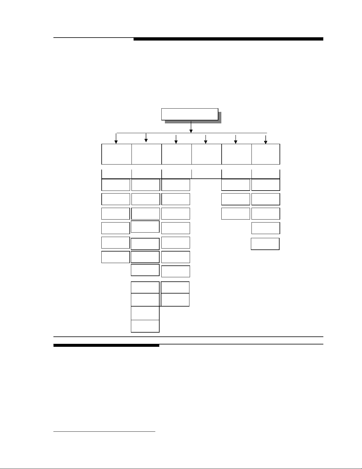
3 Programming and Configuration
The KINGBIRD operating functionality is determined by how you configure individual parameters
of
“
Program blocks
how to configure the specific parameters (“ sub-block ”) of each . The following diagram gives an
overview of the program blocks and sub-blocks
F1 Scale
“ in
setup mode. This chapter discusses basic features of program blocks and
F2 Application F3 Configure
Environment
:
Setup Mode
General Information
The KINGBIRD setup parameters are divided into five program blocks. each program block is
divided into sub-blocks where you
chapter describes each program block and sub-block in
configure each param
The KINGBIRD program blocks use several standard conventions . This section gives general
information on keystroke functions , navigation procedures , and program block access and
F1.3
Capacity
F1.4
Increment size
CAL
F1.6
Zero Adjust
F1.7
Span Adjust
F1.8
Gravity Adjust
F2.3
Tare function
F2.4
Zero function
F2.4.1
PB Zero
F2.4.2
AZM
F2.4.3
AZM Net
F2.4.4
Zero cursor
F2.4.5 Negative
blanking
F2.5 Motion
Sensitivity
F2.5.1
Motion blanking
F2.6
Low pass Filter
F2.6.1
Noise filter
eter
before you begin using the KINGBIRD indicator .
COM1
F3.1.1
Baud rate
F3.1.2
Data bits
F3.1.4
Parity
F3.1.5
Checksum
F3.1.6
STX
F3.2Manual/Aut
o print
F3.3
Language
F3.4
Output mode
F3.4.1
Data format
select
F5.1.1
and configure individual operating parameters . This
Sample interval
F5.3Consecutive
detail .
F5.2
Accumulation
number
You should read through this chapter and
F6.2Calibratio
COM1 test
Keyboard test
Factors
F6.4
Print setup
F6.5Reset to
factory
F6.6
F6.7
exit .
Page 11

9
Keystroke Functions
The following keys are used to configure the program blocks when in setup mode .
Master and Service Mode
The Master and Service mode is two setup modes which the KINGBIRD term
customer and service person.
The master mode allows you to match your
can change the settings of your
block except the F1 block, since the param
performance .
The Service mode allows the W&M and the service person to enter to
all
the program blocks .
Please see the following description of how to enter into the master and service .
Program Block Access
(Master and Service mode )
In order to configure the program blocks the programmer must enter the setup mode. The difference
between Master and Service mode is determined by the SW1-1 , if the SW1-1 is in OFF position ,
allow you to enter into Service mode , otherwise is the Master mode .
Open the KINGBIRD term
keys simultaneously.
W&M
seal
In order to secure the KINGBIRD term
im
pact the weighing accuracy performance , turn switch SW1-1 off.
In legal-for-trade applications, after checking for correct operation and turning switch SW1-1 off, the
KINGBIRD term
and the one in the W&M screw , and secure
Zero
Tare
Clear
Total
ZERO Backup to the previous step.
TARE Moves the blinking
CLEAR Resets
and/or allows programmer to skip to the end of setup.
a
TOTAL Moves the blinking
digit.
num
edit
eric
cursor
left
one digit.
data entry value to zero
edit
cursor right one
Mode
Enter
Print
allows the programmer to view the next in
list.
ENTER Accepts/terminates
MODE Increments the num
scale
and
scale to
activate
eter in
your specific weighing needs, In the Master mode you
functions .The master mode contains
this block
inal
and
select
the position of the SW1-1 and press the ENTER and ZERO
inal
from
accidental or
inal
enclosure must be "sealed." , loop the wire through the hole in the bottom case
it
with
a
seal.
eric
data entry digit and/or
a
selection
a
data entry.
will im
pact to the
calibrate
inal
provides to
scale
weighing accuarcy
the scale,
unintentional changes in setup mode to
all
the program
it
contains
that will
Page 12

10
General Programming
Procedure
After accessing the setup mode, each program block and sub-block can be configured according to the
procedure outlined in the following pages. If the term
recommended
correctly as the application and/or environment dictates.
Once the F1 prompt is displayed, the MODE key
enter the block.
Once ENTER is pressed, the KINGBIRD advances to the first param
shows the sub-block number and the current value setting. Press ENTER to
to the next sub-block or press the MODE key to toggle through the choices until the desired selection is
displayed. After the desired selection is displayed press the ENTER key to
value. Continue this procedure throughout the setup routine until
made.
Program Block Exit
To
exit
setup, press the CLEAR key to advance to the CALOFF display. then ENTER key. The
KINGBIRD term
S1-1 can be turned off to secure the terminal.
Default Settings
The following is
inal is
being configured for the first
that
the programmer configure each program block to assure the term
will
skip to the next block and the ENTER key
eter in
all
changes required have been
inal will exit
setup and return to the norm
al
operation mode. At this point, the switch
a list of
the factory default setup parameters in the terminal.
State Description
F1.2 2 Calibration Units = kg
F1.3 100 Scale Capacity
F1.4 0.01 Scale Increment Size
F1.6 Zero Adjust, no default
F1.7 Span Adjust, no default
F1.8 16 Geo Value
F2.1 0 Alternate Units = None (unit switching disable)
F2.3.1 1 Tare Enabled
F2.3.2 0 Tare Interlock Disabled
F2.3.3 0 Auto Tare Disabled
F2.3.4 0 Auto Clear Tare Disabled
F2.4.1 1 Pushbutton Zero Enabled, 2% range
F2.4.2 1 Auto Zero Maintenance Enabled within 0.5d
window
F2.4.3 0 Auto Zero Maintenance in Net Mode Disabled
F2.4.4 1 Zero Cursor Enabled
F2.4.5 0 Display the negative weights
F2.5 1 Motion Sensitivity ± 0.5 increments
F2.5.1 0 Blanking Disabled in motion
F2.6 2.0 Filter Corner Frequency
F2.6.1 0 Noise Filter Disabled
F3.1 1 COM1
F3.1.1 1200 Baud Rate
F3.1.2 7 Data bits
F3.1.4 2 Even Parity
F3.1.5 0 Checksum Disabled
F3.1.6 0 STX Disabled
F3.2 0 Manual print w/ interlock
F3.3 0 Print in English
F3.4 1 Demand output
F3.4.1 0 Print Format = Displayed Weight Only
F5.1 0 Indicator Weighing Mode , normal weighing
F5.2 0 Manual accumulation
F5.3 0 Disable consecutive number
F6.1 0 No Expanded Display Mode
F6.2 xxx Edit Cal. Factors, no default
F6.4 Print Setup, no default
time it
inal is
setup
the block. The display
accept
accept
the value and advance
the
is
will
Page 13

11
0
F6.6 0 RS232
serial port test
F6.7 0 Keyboard test
F1 Scale Interface Program Block
The
scale
interface program block allows the user to set and
performance.
Press Mode to skip to the next program block. Press Enter to access the
and configure the sub-blocks.
F1.2 Calibration Units
Sub-block
[F1.2 X] CALIBRATION UNITS
weights
X = 1
X = 2
X = 3
X = 10
F1.3
Scale
Capacity
Sub-block
[F1.3 ]
[XXXXX] Current
capacities
Increm
-ent
size
0.001
0.002
0.005
0.01
0.02
0.05
0.1
0.2
0.5
1
2
5
10
20
F1.4 Increment Size
Sub-block
ANALOG LOAD CELL SCALE CAPACITIES (lb or kg)
1000
1
2
5
10
20
50
100
200
500
1000
2000
5000
10000
20000
[F1.4
]
that will be
used for calibration .
lb
kg
g
Newton
SCALE CAPACITY
scale
from the capacity
1500
-
3
-
15
30
-
150
300
-
1500
3000
7500
15000
30000
2000
2
4
10
20
40
100
200
400
1000
2000
4000
10000
20000
40000
INCREMENT SIZE
F6.5
capacity ,
table in
2500
-
5
-
25
50
-
250
500
-
2500
5000
-
-
50000
Reset to Factory, no default
:
Enter the value for X
available
for numer
chapter one are perm
3000
3
6
15
30
60
150
300
600
1500
3000
6000
15000
30000
60000
4000
4
8
20
40
80
200
400
800
2000
4000
8000
20000
40000
-
calibrate
that
ic
entry editing , Note
the features
scale
interface program block
corresponds to the type of
that
itted .
5000
5
10
25
50
100
250
500
1000
2500
5000
10000
25000
50000
6000
6
12
30
60
120
300
600
1200
3000
6000
-
30000
60000
7500
-
15
-
-
150
-
-
1500
-
-
-
-
-
8000
8
16
40
80
160
400
800
1600
4000
8000
-
40000
-
that
affect weighing
only
legal scale
10000
10
20
50
100
200
500
1000
2000
5000
10000
20000
50000
-
test
Page 14

12
Current Increment Size is displayed for Selection
valid selections .
Calibration Sub-block
[CAL
X ]
SCALE CALIBRATION PROCEDURE
List
editing . Press MODE key to toggle through the
X = 0 Skip calibration procedure
X = 1
[E SCL ] Empty
[15 CAL] Delay while
and motion is detected
[Add Ld ]
[‘0’0000] Enter
scale
Continue calibration
scale
Place test
test
capacity .
platform and press ENTER to continue .
initial is et (
at
this step , the display returns to the [E SCAL] prompt .
weight on the
weight value .No decim
[15 CAL ] Delay while span is
display returns to the [Add Ld ] prompt .
[CAL d ]
“
Calibration done ”is displayed momentarily .
F1.6 Zero Calibration Adjust Sub-block
[F1.6 X] ZERO CALIBRATION ADJUST
X = 0 Skip zero adjustment
X = 1 Store current
initial on scale as
[15 CAL] If zero calibration adjust is
reading are being taken.
Scale
motion causes the countdown re-start from 15. Pressing CLEAR
countdown aborts zero adjust so
countdown reaches "0," the
scale
F1.7 Span Calibration Adjust Sub-block
[F1.7 X] SPAN CALIBRATION ADJUST
display counts down ) . If the motion sensitivity is not disabled
scale
platform , and press ENTER .
al
point is perm
et (
display counts down ) . If the motion is detected
itted .
Maximum
test
weight is 105% of full
at
this step then the
zero.
selected
that
the motion sensitivity selection can be modified. When the
reading is adjusted to the new zero reading.
the display counts down from 15 to 0 while
at
any
time
during the
scale
X = 0 Skip span calibration adjust
X = 1 Perform span calibration adjustment.
[ ‘0’0000] Num
showing " 0" then span adjust is aborted.
[15 CAL] After valid (non-zero) data entry, the display counts down from 15 to 0 while
taken.
Scale
motion causes the countdown to restart from 15. Pressing CLEAR during the
countdown aborts span adjust so
countdown reaches "0," an
over-capacity or in expand mode, "E 35" is displayed to show
performed. If the entered weight is more than
Press any key to
F1.8 Geo Code Sub-block
[F1.8 X X ] GEO CODE
Values from 00 to 31 are accepted. The Geo Code is used to compensate for differences in the
eric
data entry of current
attempt is made to calculate
clear "E
35" and proceed to the end of setup.
scale test
load. If the ENTER key is pressed with the display
that
the motion sensitivity selection can be modified. When the
the span calibration. If the weight is negative,
that
span adjustment cannot be
twice the
original displayed weight, "E 35" is displayed.
scale
readings are
Page 15

13
acceleration of
moved to another. Gravitational
approxim
increment
size of
ately
0.2 parts per thousand. The default Geo Code is 16 .
F2 Application
Environment Block
[F2 ] APPLICATION ENVIRONMENT
gravity due to
latitude
and
acceleration
elevation if
the
scale
was calibrated in one location then
decreases with increasing height above sea
level
0.2 parts per thousand every 1000 meters. The Geo Code has 32 settings with an
by
Press MODE to skip to [F3 ].
Press ENTER to continue.
F2.1 Alternate Units
Sub-block
[F2.1 X] ALTERNATE UNITS: Enter
a
secondary unit.
X = 0 None
X = 1
l
X = 2 kg
X = 3 g
X = 10
Newton
F2.3 Tare Operations
Sub-block
[F2.3 ] TARE OPERATIONS
Press MODE to skip to [F2.4 ], press ENTER to continue.
[F2.3.1 X] ENABLE TARE
X = 0 Tare disabled
X = 1 Only Pushbutton Tare enabled
[F2.3.2 X] TARE INTERLOCK: The
how
tare
m
eets
legal-for-trade requirements by making the following restrictions:
•
Tare weights can be cleared only
•
Tare can be entered only when the
•
Previous
disabled)
X = 0 Tare Interlock disabled
X = 1 Tare interlock enabled
[F2.3.3 X] AUTO TARE
X = 0 Auto Tare disabled
a
value for X
b
:
Enter
a
value for X
tare
values can be cleared and entered in
at
gross zero (with the
scale is in
tare
values must be cleared before
that
corresponds to the unit of measure desired as
that will
enable or disable Tare.
interlock feature, if enabled, places
legal
-for-trade applications. Specificaly,
scale
empty)
gross mode
a
new
tare
value can be entered (chain
certain lim
tare
itations on
interlock
tare
Page 16

14
X = 1 Auto Tare enabled after no motion following > 5d when in GROSS mode
[F2.3.4 X] AUTO CLEAR TARE
X = 0 Auto
X = 1 Auto
F2.4 Zero Operations Sub-block
[F2.4 ] ZERO OPERATIONS
Clear
Clear
Tare disabled
Tare enabled,
tare
Press MODE to skip to [F2.5 ], press ENTER to continue.
[F2.4.1 X] PUSHBUTTON ZERO ENABLE
X = 0
Pushbutton zero disabled
X =1Enable pushbutton zero and AZM within ±2% FS range
X =2Enablepushbutton zero and AZM within ±20% FS range
[F2.4.2 X] AUTOZERO MAINTENANCE: Auto Zero Maintenance (AZM) autom
compensates for sm
all
changes in zero resulting from m
range (+/-) around gross zero within which KINGBIRD
scale
exceeds the weight range, the KINGBIRD term
X =
0 No
AZM or zero capture
X = 1 AZM within 0.5 d window and power-up zero capture ±2%.
X = 2 AZM within 1d window and power-up zero capture ±5%.
X = 3 AZM within 3d window and power-up zero capture ±10%.
[F2.4.3 X] AZM IN NET MODE
X = 0 Disable AZM in net mode
X = 1 Enable AZM in net mode
[F2.4.4 X] ZERO CURSOR
X = 0 No Zero cursor
X = 1 Zero cursor enabled
[F2.4.5 X] UNDER ZERO BLANKING
X = 0 No Under Zero blanking
X = 1 Blank Display and internal signal “Under Cap
zero.
F2.5 Motion Sensitivity Selection Sub-block
[F2.5 X] MOTION SENSITIVITY SELECTION: The motion detection feature determines when
no-motion condition exists on the
stable. Printing, pushbutton zero, and
c
ommand.
Stability detection occurs over
amount of motion (in
X = 0 Motion detector disabled
X = 1 1.0 d motion sensitivity
X = 2 3.0 d motion sensitivity
[F2.5.1 X] MOTION BLANKING
X = 0 Blanking disabled
F2.6 Low Pass
Corner Frequency
X = 1 Blank the weight display during motion
[F2.6 X.X] LOW PASS FILTER CORNER FREQUENCY
X.X is the num
Filter
a
scale
increments).
eric
data entry for the low pass
autom
atically
at
power-up
scale
platform. The sensitivity
tare
entry
will
predefined period of
filter
clears
at
gross zero
aterial
build-up
will
capture zero . If residual weight on the
inal will
not capture zero.
lets
you
acity” if
wait for
time
gross weight is greater than 5d under
level
determines what is considered
scale stability
and allows
before carrying out the
a
predetermined
corner frequency (0.5-9.9Hz).
atically
select
the weight
a
“acceptable”
Page 17

15
[F2.6.1 X] NOISE FILTER ENABLE/DISABLE
X = 0 Disable noise
X = 1 Enable noise
F3 Configure
Serial I/O Block
[F3 ] CONFIGURE SERIAL I/O
Press MODE to skip to [F5 ].
filter
filter
Press ENTER to continue.
F3.1
Select
Sub-block
F3.2 Manual and Auto
Print
F3.3Language Selection
F3.4 Serial Data Out
Sub-block
Serial Port
[F3.1 ]
COM1 CONFIGURATION
X = 0 Skip to [F3.2 ]
X = 1 Enter into the block to configure the parameters
[F3.1.1 ] DATA RATE
[ XXXX]
Select
[F3.1.2 ] DATA BITS
X = 7 7 data bits
X = 8 8 data bits
[F3.1.4 X] PARITY
X = 0 No parity
X = 1 Odd parity
X = 2 Even parity
[F3.1.5 X] CHECKSUM
X = 0 No checksum sent
X = 1 Checksum enabled
[F3.1.6 X] STX setting
X = 0 No STX
X = 1 Send STX
[F3.2
]
MANUAL AND AUTO PRINT
X = 0 Manual print and disable print interlock
X = 1 Manual print and enable print
X = 2 Enable Auto print interlock , threshold is 10d display weights
[F3.3
]
LANGUAGE SELECTION
X = 0 Printout in English
X = 1 Printout in Chinese
[F3.4 X] SERIAL DATA OUT
X = 0 Continuous mode. If continuous mode, the display skips to [F5].
:
300, 1200, 2400, 4800, or 9600 baud
inte
rlock , threshold is 10 d display weight
:
Page 18

16
X = 1 Demand mode. Continue to next step.
X = 2 SICS Protocol. If 2 is selected, the display skips to [F5].
[F3.4.1 X] DATA FORMAT (Demand Mode output only) X
= 0 Single line. Displayed weight only
X = 1 Single
line ,
X = 2 Multiple
X = 3
Ticket
form
F5 Weigh Mode Block
[F5 ] WEIGH MODE
Press ENTER to continue.
Press MODE to skip to [F6 ].
F5.1 Enter Weigh Mode
Sub-block
[F5.1 X] WEIGH MODE SELECTION X
= 0 Norm
al
weighing. Skip to [F5.2 ] X =
1 Anim
al
X = 2 Counting , skip to [F5.2 ]
X = 3 Hold , skip to [F5.2 ]
Refer to Chapter 4 for
[F5.1.1 ] ANIMAL WEIGHING SAMPLE INTERVAL
Press MODE key to toggle 3, 5 and 10 seconds and ENTER key for acknowledgement .
gross ,
tare
line ,
at ,
and net .
gross ,
tare
determined by
and net .
selected
weighing, skip to [F5.1.1 ]
detail of
each weighing mode .
weighing mode.
Page 19

17
F5.2 Accumulation
Sub-block
[F5.2 X ] ACCUMULATION
X = 0 Auto-accumulation disable
X = 1 Auto-accumulation enable
Accumulation function is not available at HOLD weighing mode.
F5.3 Consecutive Number Sub-block
[F5.3 X] CONSECUTIVE NUMBER
X = 0 Consecutive number disable
X = 1 Consecutive number enable
F6 Diagnostics Block
[F6 ] DIAGNOSTICS
Press MODE to skip to [CAL OFF ].
Press ENTER to continue
F6.1 Expanded Display
Sub-block
[F6.1 X] EXPANDED DISPLAY.
X = 0 Norm
X = 1 Weight displayed in minors ( 1d = 10 minors )
al
display mode
F6.2 Edit Calibration Factors Sub-block
Note : please don’t
change the factors ,
otherwise will impact
the scale performance ,
suggest to record that
figure for later service .
___________________
F6.4 Print Setup
F6.5 Reset to Factory Defaults
[F6.5 X] RESET SOFTSWITCH CONFIGURATION TO FACTORY SETTINGS
X = 0 Skip this sub-block
X = 1 Restore
[LOAd 0] Are you sure prompt. Toggle to “1” for yes, “0” to abort, then press ENTER . If “yes”, soft
switches are now set to the factory default values.
F6.6 COM1 Serial Port Test Sub-block
[F6.6 X ] COM1 SERIAL PORT TEST
all
[F6.2 X] EDIT CALIBRATION FACTORS
X = 0 Skip this block
X = 1 Edit calibration factors
[123456] Zero factor,
[123456] Span factor,available for num
[123456] Span factor,
[F6.4 X] PRINT SETUP X
= 0 Skip this sub-block
X = 1 Print setup report
settings to factory defaults
available
available
for num
for num
eric
data editing
eric
data editing, page 1
eric
data editing, page 2
Page 20

18
X = 0 Skip this sub-block
X = 1 Continue to
test
The Serial Interface Test tests the
test , left
two digits show the transm
8142Pro scrolls from 1 to 99. If the data is equal ,
serial
interface
test is
F6.7 Keyboard Test Sub-block
[F6.7 X] KEYBOARD TEST
the COM1
serial
ports COM1. Shorten TXD and RXD, Press ENTER to start the
itted data,
the right two digits show the received data.
that
means the
serial
port is working fine . The
useful in hardware diagnostics. Press ZERO key for
exit
the
test .
X = 0 Skip this sub-block
X = 1 Continue to
test
4 Kingbird Operation
This chapter provides general information
term
inal
and to perform
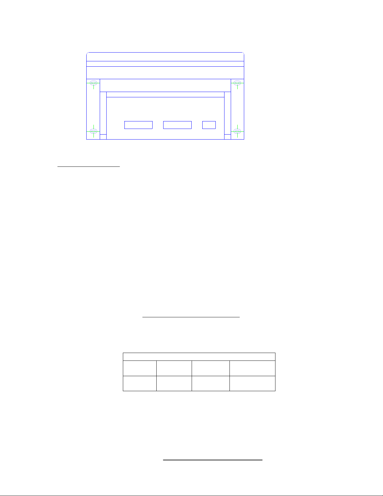
Kingbird Display Area
.
The KINGBIRD has
a
presented .The display is pictured below
The display indicates
using prompting . Error messages are displayed as they occur .
Annunciators point to labels in the legend directly below the display area . Annunciators indicates
• Center-of-Zero ( 0 ) :
The Center-of-zero annunciator indicates
• Scale instability ( ~ )
The
scale
instability annunciator indicates
when the
scale is
• Weighing mode ( G
scale
stable . The sensitivity of motion detection is adjustable in setup.
the keyboard
its
functions , and step-by-step instructions describing each operator function
single 7-segment num
that an
eric
operator
will
display where
need to become fam
scale
data and operational messages are
iliar
with the
:
weight unless you are in setup mode programming the KINGBIRD or
that
the
scale is
within +/- 1/4 increment of gross zero .
that
the
scale is in
motion . The annunciator
will
turn off
ross and N
et
)
:
Page 21

19
The Kingbird
press the TARE key or enable the autom
will be in
will be in
gross mode .
net mode when
a tare is active .
atically tare
• Special weighing mode ( Animal weighing and Counting )
The Kingbird provides anim
counting mode , the
.
The
“
Dyn
“
weighing mode , indicator
annunciator as well as .
• Kg
The annunciator
annunciator stands for the anim
will be
al
weighing and Counting special weighing mode . When
“
Pcs
“
annunciator
will
display the animal’s “stable
will be
turned on , and the display is the quantity of the parts
al
weighing , after the sampling period in the anim
turned on when the unit of the weight is kg .
Terminal Keypad
Zero
Tare
Clear
Total
Mode
The Zero key is used to compensate for sm
changes in weight when the
These changes in weight are most often caused by
m
aterial
spilling onto the weighing platform. To
zero the indication of weight, press this button. The
Zero range is programmed in the setup .
The Tare key is used to subtract the weight of the
object
on
the
scale
indications of weight. This is most often the weight
of an empty container. Once this value is “tared”,
the indication of weight
weight. To
on the
tare
scale
and press this button.
The
Clear
key is used to
tare
value. To
clear
The indication of weight
showing the
platform.
total
weight of the objects on the
The
Total
key is used to accumu
press the key
will
platform to the accumulation register , and the weight
will
blink once to acknowledge the accumulation is
done. And long press
The Mode key function is different in each weighing
mode
:
(1). F5.1=0 Norm
switch between the primary and secondary weighing
units. To change weighing units, press this
button. Each
the display units from the primary to the secondary
units, or back to the primary from the secondary.
(2).F5.1=1 Anim
cy
cle .
(3).F5.1=2 Counting . Short press for set the sample
parts quantity
al
initiation of
al
;
Longer press for
Tare may be autom
function . If no
atically
tare is active
”
weight, and turn on the “Dyn
scale
platform is empty.
platform
will
the scale,
change to
place an
from
subsequent
indicate
empty container
the
clear a
tare
will
previously entered
value, press this button.
return to the gross mode,
scale
late
the weight ,
accumu
late
the weight on the
Total
for recalling the summary.
weighing . It allows the operator to
this button
weighing .
will
Initiate
recall
either switch
the weighing
the
acquired when you
the KINGBIRD
select
the
al
”
all
net
Page 22

20
Operator Functions
Zero the
Tare Operations
Print Operations
Scale
Accumu
late
Operations
Enter
Print
Zero
Tare
Clear
Enter
Print
Total
corresponding weights .
(4).F5.1=3 Hold .
The Transact (Print) key is used to
Initiate
the cy
cle
.
initiate a serial
output of the weight data. To request this
transmission of data, press this button. The
form
at of
the data string is determined in set-up.
This key is also used to
or programming question.
accept a
response to
If the
scale
platform is empty and the NET cursor is
NOT
lit,
press the Zero button to compensate for
any m
aterial
which may be on the
The zero button is
that is
between
±2% (or
limited to
±20%, if programmed
scale
compensating weight
accordingly) of the scale’s weighing capacity.
Determine the weight of the m
container, weighing in the NET mode
1.
Place an
empty container on the
2. Press the Tare button
3.
Fill
the container or
place a filled
equivalent weight on the
4. The indicator
NET cursor
will
display the net weight and the
will
light.
aterial
scale
inside
scale
container of
Clearing
1. If desired,
2.
3. Press the Transact (Print) key.
Accumu
1. If want to have the summary of the
a tare
With the
weight:
scale in
the net weight mode (a
previously entered), press the
cursor
will go
displayed.
Printing
out and the net weight
a
weight:
tare
the weight of an empty container
using the steps described above.
Place a
load on the weighing platform.
late
the weight if disable the autoprint function
them , you may set [F5.2 ] to 0 ,
command by press the
Total
Clear
key .
key. The net
will
all
that
actual
a
setup
platform.
a
platform
tare
weight
be
:
transaction or some of
means you may
initiate
the
Page 23

Advanced Operator Functions
The following paragraph
weighing mode is determined by F5.1 . MODE key is designated as special function key in each
mode .
Norm
al
weighing mode
Basiclly ,
the KINGBIRD Term
1. Mode key is
2. Serial port communication
output form
3. In this mode , accumulation may be set to manual or auto .
4. The print out also may be set to manual print or autom
acted as
at
are
selectable in
Anim
al
weighing
Note: the feature of print
&accumulation are not
available for the “
Normal” weight data in the
animal weighing mode .
Ticket format :
Animal Weighing
CN 3
GROSS 342.0kg
TARE
NET 231.5kg
Counting
110.5kg
2. When the weight is stable ,
will
introduce the deta
inal
unit switch .
:
both Continuous and demand output are
the window
.
can be used
will
il
at
F3.4.1 . Refer to Appendix 1 for
blink once ,
operation in each weighing mode . And each
simp
initiate
le
weighing application ( [F5.1=0] ) .
the command and the weight on
that
stands for the data is summarized
available .
all
the output form
The demand
at .
atic
print out .
The weight data may be unstable when weighing the livestock , the
KINGBIRD term
feature ,
it will
inal is
provided with the capability of anim
capture the weighing data in
certain
al
weighing
sample interval and
display the average weight until press ENTER or MODE to continue next
cy
cle .
1. Set [F5.1]=1 , enable the anim
change the printout form
2. After set the [F5.1] to 1 , [F5.1.1]
MODE key to
select
the sample interval , 3,5 or 10 seconds . Then
the setup mode . Start the anim
3. Move the livestock to the platform and press MODE key to
weight sampling . The display shows
at to
al
weighing , and this
anim
al
weighing
will be available
al
weighing
“
DynA ” for the
will
ticket
form
for you to press
certain
autom
at .
initiate
atic
exit
interval
time .
4. After the sampling , the display shows
average of
all
the sampled weight during the interval
5. The printout is determined by F3.2 , if
KINGBIRD
will
send out the weight in
otherwise , press ENTER/PRINT
to “norm
al ”
weighing.
6. The accumulation is determined by F5.2 , if
accumulation , after showing the stab
accumu
lated
autom
aticly. If
the auto-accumulation is disabled , and
when display the stable weight , press ENTER/PRINT key
accumu
late
the weight .
7. Come back to number 3 for another weighing cy
8. Refer to the
comp
GROSS 168.5kg
left
side for the standard
atible
with the 16-column mini-printer .
a
stable weight ,
it is
autom
ticket
will initiate
it is
le
weight and the data
ticket
printout , KINGBIRD is
that is
the
time .
atic
printout ,
form
at
through RS232 ,
the print and return back
autom
atic
will
be
will
cle .
the
Ticket Format :
Piece Counting
20
CN 5
Page 24

The KINGBIRD is
provided with the
capability basic
parts counting
function .
1. Set [F5.1]
=2 , the
printout is
autom
changed to
parts
atic
counting
ticket
form
at .
Page 25

21
Note: the feature of print
&accumulation are not
available for the recalled
weight in the counting mode .
2. After
piece
of the weight on the platform which is based on the APW
display
parts as the number showed in the display on the platform . Press
MODE key to
acknowledgement to establish the APW .
3. Then , the display is the quantity of the parts .
4. If want to change the APW , short press the MODE key , display
shows
5. Long press MODE key
quantity .
6. The printout is determined by F3.2 , if
KINGBIRD
otherwise , press ENTER/PRINT
7. The accumulation is determined by F5.2 , if
accumulation, after
autom
the stable quantity , press ENTER/PRINT key
quantity .
8. Refer to the
Peak Hold
Ticket format :
Maximum Weight
CN 6
Max 359.0kg
KINGBIRD is comp
With this feature , KINGBIRD can be used
system , KINGBIRD
maximum weight in the
1. Set [F5.1 ] = 3 and
2. Press MODE key
3. ENTER/PRINT key for print
, MODE key for
4. Refer to the
comp
Controller PCB Switches and Jumpers
SW1 Switch Settings
1
Setup/Calibration Enable = On
Norm
al
Operation = Off
2
Display Comm
3
Not Used (Should be Off)
4
Test Mode (Must be Off)
a Tail = On
Jumper W1 (Analog Version)
Installed = 2 mV/V Load
Not Installed = 3 mV/V Load
Cells
exit
the setup mode , KINGBIRD
will
judge the APW ( average
weight ) already exist or not , if yes , the display is the quantity
will
show
“
Set PC
select
” , that
means put the sam
e
from 5 ,10 , 20 ,50 and 100 . Press ENTER for
“
Set PC
“ ,
then repeat the Number 2 procedure .
will recall
the corresponding weight or the
it is
autom
atic
printout ,
will
aticly . If
send out the weight in
it is
stable , the quantity
the auto-accumulation is disabled , and when display
ticket
will initiate
it is
will be
form
at
through RS232 ,
the print .
autom
accumu
will
accumu
atic
left
side for the standard
atible
with the 16-column mini-printer .
will
compare each sampled weight and hold the
test
duration .
ticket
printout ,
at
the tension or force
exit .
will
initiate
left
atible
with the 16-column
start the hold function .
a ticket
another cy
cle .
side for the standard
ticket
and return to
printer .
ticket
“
norm
printout , KINGBIRD is
Cells
; if
not , the
quantity of the
lated
late
the
test
al ”
weighing
Page 26

22
5
E2 Internal
RAM Error 1. Check
power
supply voltages
E3 EEPROM
Memory
Error 1. Check
power
supply
voltages
E4 External
RAM Error
Replace
main
logic P
CB
E7 A/D Circuit
Malfunction
or No
1. P
rogram for
correct
load cell type
E16 Internal
Math Error Press Clear to acknowledge,
unit will reset.
E32 Insufficient
Test Weight
Used for
Recalibrate
using m
ore test weights
E34 Test Weight Exceeds
105%
of
Use less than 105% of capacity
press Clear and re-enter
E35 S
pan Calibration
Error Recalibrate.
If error persists,
check
progra
mm
ing or replace
E36 An
alog Load Cell Out of Range
1. Recalibrate
E50 Weight
Can’t
be Displa
yed in
Some alternate
units combinations
are illegal.
Choose
another
EEE P
ositive
more than Zero Capture
1. Remove material from scale
base
-
EEE Negative
more than Zero Capture
1. Disable AZM in setup
------ No Ana
log Load Cell Detected
1. Check
load cell wiring
T
roubleshooting
Procedures
If operational difficulties are encountered, first obtain as much information as possible regarding the
problem. Failures and malfunctions often may be traced to simp
im
Error Code
by substitution. Replacing the suspect part with known good part .
proper setup,
The following
Error
Code
E1
etc. If
simp
le
table lists
Description
Program Memory Error
the error codes, description, and corrective measures.
le
causes such as loose connections,
causes cannot be found, additional troubleshooting is best performed
Corrective Measures
1. Check power supply voltages
2. Replace main logic PCB
2. Replace main logic PCB
2. Reprogram, recalibrate
3. Replace main logic PCB
Analog Load Cell Connected
Calibration
Capacity
Alternate Units
Limit of 2% of Scale Capacity
Limit of 2% of Scale Capacity
Voltage Checks
AC Power Test
--
Main Logic PCB Voltage
test
load cell
2. Replace load cell
Use
a multi-meter to
-15% and +10% of the nom
2. Check load cell and cables
3. Check power supply voltages
4. Replace main logic PCB
scale build or disable alternate units
2. Disable AZM in setup
3. Cycle power
2. Calibrate scale
3. Cycle power
2. Replace load cell
3. Replace main PCB
check the AC input power. Input power must be within
inal AC line
voltage.
Page 27

23
RS232 Serial Output Test
Verify voltage of 5VDC between + and – Excitation. If the Kingbird
Term
inal
has power and there is no excitation voltage, replace the PCB.
Use the following
operational.
test
procedure whether the RS232
serial
port is
1. Remove power from the Kingbird Term
cable
from the printer.
2. Set the volt m
eter to
read 20 volts DC.
3. Connect the red lead to pin 2 of the printer end of the data
connect the black lead to pin 7.
4. Apply power. The m
eter
In Demand mode, the m
fluctuation.
In
Continuous mode, the m
should read as follows:
eter
should read between –5 and –15 with no
eter
should fluctuate between –5 and +5
continuously. The constant fluctuation on the m
display indicates the scale/indicator is transm
To
test
the Demand baud rates, press the Transact (Print) key. The display
should fluctuate between -5 volts to +5 volts for the duration of the
transmission, then become stable again. This indicates the term
transm
itted
data.
Another way to diagnose the
serial
port is to
diagnostic . connect the pin2 and 3 together and
ENTER to continue the checking , if the two digits shows on the display is
same .
that
means the RS232 is working fine .
inal
and disconnect the data
eter
display on the m
itting
information.
utilize
the Kingbird ‘s self-
set the [F6.6 ] to 1 , press
cable
inal
and
eter
has
Page 28

24
1
31113
Overlay and
key
board
assemb
ly
132085
Kingbird
,
print circuit board
assemb
ly
6 Spare Parts
Recommended spare Parts
To minim
spare parts on hand:
Order No. Description
ize
down-time, METTLER TOLEDO recommends
that
you keep
125111
100841
Kingbird , Transformer
Kingbird , VFD tube
Page 29

25
S
C
NOTES
B C D D D D D E F G G I J K
Appendix I RS232
Serial
Interface
The Kingbird term
programmed for several functions. The output can be configured as demand
mode for simp
or remo
te
display.
Serial Data Output in Demand Mode
The KINGBIRD term
command is issued using the ENTER/PRINT pushbutton, The data form
baud rate, checksum, parity,
data is output in an 10-bit ASCII frame which includes: 1 start bit, 7 data
bits, 1 parity bit, and 1 stop bit. Parity is
using F3.1.4. Checksum and STX can be enabled or disabled using F3.1.5
and F3.1.6. All demand mode printing is inhibited during motion and when the
weight is under gross zero. Printing is allowed on power-up whether or not zero
is captured if AZM is enabled (param
available
formats
SINGLE LINE DISPLAYED WEIGHT FORMAT
le
output to
are:
inal
inal will
has
a
bi-directional RS-232 port
a
printer or continuous output mode to computer,
transm
it
etc.
RS232C
are
selectable in
selectable as
serial
eter or
that may
data when
the setup mode. The
none, odd, or even
sub-block F2.4.2). The
be
a
print
at,
serial
DATA
T
X
X
X
X
X
X
S
L
X
P
B
S
P
N
H
C
R
L
K
F
NOTES
B -STX = Start of Text character (optional). If F3.1.5 = 1, STX and checksum characters
position.
C -X = weight data digit, minus sign (-) for negative weight or tare, or space character
position.
D -X = Weight data digit or decim
-SP = Space character.
F G -Space character and N
if the displayed weight is gross.
I -CR = carriage return character.
J -CHK = checksum character (optional). Checksum
K -LF =
al
point character. E
“LB”
sent for pounds when F1.2 = 1, “kg” sent for kilograms when F1.2 = 2, “g” sent for grams
will be
line
feed character..Chapter 10: Appendices
sent if displayed weight is
will be
a
net weight. Space character and G
sent with STX if F3.1.5 = 1.
will be
will be
sent in this
sent in this
will be
sent
Page 30

26
SINGLE LINE GROSS/TARE/NET FORMAT
S
C
N
A B B B B B B B C D C E C F F F F F F F C D C G C I I I I I I I C D C J L M N
Line
S
C
NOTES
A B B B B B B B C D C E F G H
Line
C
NOTES
I I I I I I I C D C J F G H
NOTES
L L L L L L L C D C M F G H
*
X
X
X
X
X
D
T
A
X
T
A
O
T
E
x
S
L
S
P
B
P
G
*
S
P
*
X
X
X
X
X
S
P
T
*
X
X
L
S
B
S
P
P
X
X
X
X
NOTES
A -STX = Start of Text character (optional). If F3.1.5 = 1, STX and checksum characters
string
B -Gross weight data field (7 characters). (* = digit, minus sign (-), or space, X = digit or decim
C -SP = Space character
D E -G = Character for gross weight.
F -Tare weight data field (7 characters). (* = digit, space, X = digit or decim
G -T = characters for
I -Net weight data field (7 characters), (* = digit, minus sign (-), or space, X = digit or decim
J -N = characters for net weight
L -CR = carriage return character
M -CHK = checksum character (optional). Checksum
N -LF =
THREE LINE GROSS/TARE/NET FORMAT
“LB” =
line
will be
pounds when F1.2 = 1, “kg” sent for kilograms when F1.2 = 2, “g” sent for grams
al
point)
tare
weight
feed character.
will be
sent with STX if F3.1.5 =1
S
P
N
L
S
C
L
B
P
H
R
K
F
sent in data
al
point.)
al
point.)
LINE 1
GROSS WEIGHT
One
Data
LINE 2
TARE WEIGHT
two
data
LINE 3
NET WEIGHT
Line
three
data
T
X
X
X
X
X
X
X
X
X
X
S
L
P
B
S
P
G
C
R
H
K
L
F
X
X
X
X
X
X
S
L
P
B
S
P
T
C
R
H
K
L
F
C
X
X
X
X
X
X
S
L
P
B
S
P
N
C
H
L
R
K
F
NOTES
A -STX = Start of Text character (optional). If F3.1.5 = 1, STX and checksum characters
string.
B -Gross weight data field (7 characters). (* = digit, minus sign (-), or space, X = digit or decim
C -SP = Space character
D E - G = Character for gross weight
F -CR = carriage return character
G -CHK = checksum character (optional). Checksum
H -LF =
“LB” =
line
will be
pounds when F1.2 = 1, “kg” sent for kilograms when F1.2 = 2, “g” sent for grams
feed character
will be
sent with STX if F3.1.5 = 1
sent in data
al
point.)
Page 31

27
I -Tare weight data field (7 characters), (* = digit, space, X = digit or decim
0 1 2 Decimal point
0
0
0
XXXX00
3 4
1
0
X1
J -T = characters for
tare
weight
al
point)
L -Net weight data field (7 characters), (* = digit, minus sign (-), or space, X = digit or decim
M -NET = characters for net weight
Serial Data Output in Continuous Mode
A 300-9600 baud continuous output may be
demand output. This data consists of 16 or 18 bytes transm
ASCII frame consisting of: 1 start bit, 7 data bits, 1 even parity bit, and 1
stop bit.The form
Character
1
2
3
4
5
6
7
8
9
10
11
12
13
14
15
16
17
18
Non-significant weight data and
Fun
ction
STX (Start of
S
tatus
Word A
S
tatus
Word B
S
tatus
Word C
Weight MSD
Weigh
t
Weigh
t
Weigh
t
Weigh
t
Weight LSD
Tare Weight MSD
Tare Weigh
Tare Weigh
Tare Weigh
Tare Weigh
Tare Weight LSD
CR (carriage return)
CKSM (Checksum – Optional)
tare
data digits
words A, B, and C is shown in below Tables .
Status Byte Definition
Status Word A
Bits0,1,2
at is:
text - Optional)
t
t
t
t
will be
transm
itted as
selected
instead of the print on
spaces. A description of the status
al
point)
itted in a
10-bit
1
0
1
0
1
0
1
Bits3,4
0
1
Bit5
Bit6
Table A-1
:
Status Word A
0
1
1
0
0
1
1
1
1
Bit
Definitions
0
0
0
1
1
1
1
XXXXX0
XXXXXX
XXXXX.X
XXXX.XX
XXX.XXX
XX.XXXX
X.XXXXX
Increment size
X2
X5
Always 1
Always 0
Page 32

28
Bit1
Positive = 0, Negative = 1
Bit2
Overcapacity ( or under zero )=1
Bit3
Motion=1
Bit4
Unit :
kg=
1
Bit5
Always = 1
Bit6
Power up =1
Bit1
Always 0
Bit2
Always 0
Bit3
Print request =1
Bit4
Expanded weight =1
Bit5
Always 1
Bit6
Always 0
Status Word B
Bits
Bit0
Function
Gross=0 , Net=1
Table A-2
:
Status Word B
Bit
Definitions
Status Word C
Bit0
Always 0
Table A-3
:
Status Word C
Bit
Definitions
Page 33

29
5 4 4 3 3 2 2 1 1 0 0
5 5 4 4 3 3 2 2 1 1 0
6 5 5 4 4 3 3 2 2 1 1
6 5 5 4 4 3 3 2 2 1
Appendix IIGravity Compensation Factors - GEO Values
Gravitational Acceleration Forces
Since the
relations apply
Owing to the centrifugal force and the flattening of the earth, the
approxim
Therefore,
equator (sam
The
approxim
load
Irregularities such as uneven density distribution in the earth’s crust or special surface structures also
influence the gravitational acceleration.
Gravitational Force Adjustment
The KINGBIRD indicator has built in compensation provisions to allow factory calibration any
in the world with destination correction capab
forces. If the
compensated
increment
Geo Value
Northern
and
southern
latitude
in
degrees and
minutes
0° 0′ —5° 46′
5° 46′ — 9° 52′
9° 52′ — 12° 44′
12° 44′ — 15° 6′
acceleration
due to the earth’s gravity depends on the location, the following causes and
:
ately 5
acceleration
ately
at
sea
parts per thousand less
a scale
calibrated with
e altitude at
each location).
due to the earth’s gravity also decreases with increasing height above sea
0.2 parts per thousand for every 1000 meters. Therefore,
level will
scale is
read 2 grams light on top of
subjected to
electronically by
size
equal to 0.2 parts per thousand.
Please contact your
the location where the
value, you have to
Height above sea-level in meters
0
325
650
325
650
Height above sea-level in feet
0
1060
6
1060
2130
975
2130
3200
at
the equator than
a
10kg load
at the
North Pole
a
1000 m
ilities to
a
different gravitational force
adjusting the geo value. The geo value has 32 settings with each
local
Weights & Measures authority for the geo value of
scale is
recalibrate
975
1300
1625
1300
3200
4260
1625
1950
4260
5330
5330
6400
1950
2275
6400
7460
acceleration
it is at
the north and south poles.
will
read 50 grams lighter
eter
(3281 feet) mountain.
compensate for variances on gravitational
at its
destination location, this can be
installed and used. If you can’t get the geo
the scale.
2275
2600
7460
8530
2600
2925
8530
9600
due to gravity is
a scale
2925
3250
9600
10660
at
level
calibrated with
3250
3575
10660
11730
the
by
a
10kg
place
Page 34

30
Northern
7 6 6 5 5 4 4 3 3 2 2
7 7 6 6 5 5 4 4 3 3 2
8 7 7 6 6 5 5 4 4 3 3
8 8 7 7 6 6 5 5 4 4 3
9 8 8 7 7 6 6 5 5 4 4
9 9 8 8 7 7 6 6 5 5 4
10 9 9 8 8 7 7 6 6 5 5
10 10 9 9 8 8 7 7 6 6 5
11 10 10 9 9 8 8 7 7 6 6
11 11 10 10 9 9 8 8 7 7 6
12 11 11 10 10 9 9 8 8 7 7
12 12 11 11 10 10 9 9 8 8 7
13 12 12 11 11 10 10 9 9 8 8
13 13 12 12 11 11 10 10 9 9 8
14 13 13 12 12 11 11 10 10 9 9
14 14 13 13 12 12 11 11 10 10 9
15 14 14 13 13 12 12 11 11 10 10
15 15 14 14 13 13 12 12 11 11 10
16 15 15 14 14 13 13 12 12 11 11
16 16 15 15 14 14 13 13 12 12 11
17 16 16 15 15 14 14 13 13 12 12
17 17 16 16 15 15 14 14 13 13 12
18 17 17 16 16 15 15 14 14 13 13
18 18 17 17 16 16 15 15 14 14 13
19 18 18 17 17 16 16 15 15 14 14
19 19 18 18 17 17 16 16 15 15 14
20 19 19 18 18 17 17 16 16 15 15
20 20 19 19 18 18 17 17 16 16 15
21 20 20 19 19 18 18 17 17 16 16
21 21 20 20 19 19 18 18 17 17 16
22 21 21 20 20 19 19 18 18 17 17
22 22 21 21 20 20 19 19 18 18 17
22 22 21 21 20 20 19 19 18 18
23 23 22 22 21 21 20 20 19 19 18
24 23 23 22 22 21 21 20 20 19 19
24 24 23 23 22 22 21 21 20 20 19
25 24 24 23 23 22 22 21 21 20 20
25 24 24 23 23 22 22 21 21 20
26 25 25 24 24 23 23 22 22 21 21
26 26 25 25 24 24 23 23 22 22 21
27 26 26 25 25 24 24 23 23 22 22
27 27 26 26 25 25 24 24 23 23 22
28 27 27 26 26 25 25 24 24 23 23
28 28 27 27 26 26 25 25 24 24 23
and
southern
latitude
in
degrees and
minutes
15° 6′ — 17° 10′
17° 10′ — 19° 2′
19° 2′ — 20° 45′
20° 45′ — 22° 22′
22° 22′ — 23° 54′
23° 54′ — 25° 21′
25° 21′ — 26° 45′
26° 45′ — 28° 6′
28° 6′ — 29° 25′
29° 25′ — 30° 41′
30° 41′ — 31° 56′
31° 56′ — 33° 9′
33° 9′ — 34° 21′
34° 21′ — 35° 31′
35° 31′ — 36° 41′
36° 41′ — 37° 50′
37° 50′ — 38° 58′
38° 58′ — 40° 5′
40° 5′ — 41° 12′
41° 12′ — 42° 19′
42° 19′ — 43° 26′
43° 26′ — 44° 32′
44° 32′ — 45° 38′
45° 38′ — 46° 45′
46° 45′ — 47° 51′
47° 51′ — 48° 58′
48° 58′ — 50° 6′
50° 6′ — 51° 13′
51° 13′ — 52° 22′
52° 22′ — 53° 31′
53° 31′ — 54° 41′
54° 41′ — 55° 52′
55° 52′ — 57° 4′
57° 4′ — 58° 17′
58° 17′ — 59° 32′
59° 32′ — 60° 49′
60° 49′ — 62° 9′
62° 9′ — 63° 30′
63° 30′ — 64° 55′
64° 55′ — 66° 24′
66° 24′ — 67° 57′
67° 57′ — 69° 35′
69° 35′ — 71° 21′
71° 21′ — 73° 16′
Height above sea-level in meters
0
325
650
325
650
Height above sea-level in feet
0
1060
23
25
1060
2130
975
2130
3200
975
1300
3200
4260
1300
1625
1950
2275
2600
2925
3250
1625
1950
2275
2600
2925
3250
4260
5330
6400
7460
8530
9600
5330
6400
7460
8530
9600
10660
3575
10660
11730
Page 35

31
Northern
29 28 28 27 27 26 26 25 25 24 24
29 29 28 28 27 27 26 26 25 25 24
30 29 29 28 28 27 27 26 26 25 25
30 30 29 29 28 28 27 27 26 26 25
31 30 30 29 29 28 28 27 27 26 26
and
southern
latitude
in
degrees and
minutes
73° 16′ — 75° 24′
75° 24′ — 77° 52′
77° 52′ — 80° 56′
80° 56′ — 85° 45′
85° 45′ — 90° 00′
Height above sea-level in meters
0
325
325
Height above sea-level in feet
0
1060
650
1060
2130
650
975
2130
3200
975
1300
1625
1950
2275
2600
2925
3250
1300
1625
1950
2275
2600
2925
3250
3200
4260
5330
6400
7460
8530
9600
4260
5330
6400
7460
8530
9600
10660
3575
10660
11730
 Loading...