

Page 1

®
Industrial Scale Terminal
Technical Manual
D15896200A
(03/05).00
www.mt.com/support
Page 2

This manual describes the operation and functionality of the JAGXTREME terminal. The software number ("B"
revision) is displayed during the power-up sequence.
COPYRIGHT
Copyright 2003 Mettler-Toledo, Inc. This documentation contains proprietary information of Mettler-Toledo, Inc. It
may not be copied in whole or in part without the express written consent of Mettler-Toledo, Inc.
METTLER TOLEDO reserves the right to make refinements or changes to the product or manual without notice.
U.S. Government Restricted Rights Legend: This software is furnished with Restricted Rights. Use, duplication, or
disclosure of the Software by the U.S. Government is subject to the restrictions as set forth in subparagraph (C) (1)
(ii) of the Rights in Technical Data and Computer Software clause at 40 C.F.R. Sec. 252.227-7013 or in
subparagraphs (c) (1) and (2) of the Commercial Computer Software-Restricted Rights clause at 40 C.F.R. Sec.
52-227-19, as applicable.
FCC NOTICE
This device complies with Part 15 of the FCC Rules and the Radio Interference Requirements of the Canadian
Department of Communications. Operation is subject to the following conditions: (1) this device may not cause
harmful interference, and (2) this device must accept any interference received, including interference that may
cause undesired operation.
This equipment has been tested and found to comply with the limits for a Class A digital device, pursuant to Part
15 of FCC Rules. These limits are designed to provide reasonable protection against harmful interference when the
equipment is operated in a commercial environment. This equipment generates, uses, and can radiate radio
frequency energy and, if not installed and used in accordance with the instruction manual, may cause harmful
interference to radio communications. Operation of this equipment in a residential area is likely to cause harmful
interference in which case the user will be required to correct the interference at his or her own expense.
ORDERING INFORMATION
It is most important that the correct part number is used when ordering parts. Parts orders are machine processed,
using only the part number and quantity as shown on the order. Orders are not edited to determine if the part
number and description agree.
TRADEMARKS
METTLER TOLEDO® ,JAGUAR®, JAGXTREME and DigiTOL are registered trademarks of Mettler-Toledo, Inc.
All other brand or product names are trademarks or registered trademarks of their respective companies.
Page 3
CUSTOMER FEEDBACK
Your feedback is important to us! If you have a problem with this product or its documentation, or a suggestion on how we can serve you
better, please fill out and send this form to us. Or, send your feedback via email to:
United States, you can mail this postpaid form to the address on the reverse side or fax it to (614) 438-4355. If you are outside the
United States, please apply the appropriate amount of postage before mailing.
Your Name: Date:
Organization Name: METTLER TOLEDO Order Number:
Address: Part / Product Name:
Part / Model Number:
Serial Number:
Company Name for Installation:
Phone Number: ( ) Fax Number: ( ) Contact Name:
E-mail Address: Phone Number:
Please check the appropriate box to indicate how well this product met your expectations in its intended use?
Met and exceeded my needs
Met all needs
Met most needs
Met some needs
Did not meet my needs
Comments/Questions:
DO NOT WRITE IN SPACE BELOW; FOR METTLER TOLEDO USE ONLY
Retail Light Industrial Heavy Industrial Custom
RESPONSE: Include Root Cause Analysis and Corrective Action Taken.
quality_feedback.mtwt@mt.com. If you are in the
Page 4
E
FOLD THIS FLAP FIRST
BUSINESS REPLY MAIL
FIRST CLASS PERMIT NO. 414 COLUMBUS, OH
NO POSTAGE
NECESSARY IF
MAILED IN THE
UNITED STATES
POSTAGE WILL BE PAID BY ADDRESSE
Mettler-Toledo, Inc.
Quality Manager - MTWT
P.O. Box 1705
Columbus, OH 43216
USA
Please seal with tape.
Page 5
DECLARATION OF CONFORMITY
Konformitätserklärung
Déclaration de conformité
Declaración de Conformidad
Conformiteitsverklaring
Dichiarazione di conformità
We/Wir/Nous/Wij/Noi: Mettler-Toledo, Inc.
1150 Dearborn Drive
Worthington, Ohio 43085
USA
declare under our sole responsibility that the product,
erklären, in alleiniger Verantwortung, daß dieses Produkt,
déclarons sous notre seule responsabilité que le produit,
declaramos, bajo nuestra sola responsabilidad, que el producto,
verklaren onder onze verantwoordelijkheid, dat het product,
dichiariamo sotto nostra unica responsabilitá, che il prodotto,
Model/Type: Jaguar and JagXtreme
to which this declaration relates is in conformity with the following standard(s) or other normative document(s).
auf das sich diese Erklärung bezieht, mitder/den folgenden Norm(en) oder Richtlinie(n) übereinstimmt.
Auquel se réfère cette déclaration est conforme à la (aux) norme(s) ou au(x) document(s) normatif(s).
Al que se refiere esta declaración es conforme a la(s) norma(s) u otro(s) documento(s) normativo(s).
Waarnaar deze verklaring verwijst, aan de volende norm(en) of richtlijn(en) beantwoordt.
A cui si riferisce questa dichiarazione è conforme alla/e sequente/i norma/e o documento/i normativo/i.
in combination with a weighing platform p oduced by Mettler-Toledo is in confo mity with the following directives and standards. r r
Council directive on the harmonization of the laws of the Member
states:
relating to non-automatic weighing instruments (90/384/EEC) amended
by directive (93/68/EEC)
relating to electromagnetic compatibility (89/336/EEC) amended by
directive (93/68/EEC; 92/31/EEC)
relating to electrical equipment designed for use within certain voltage
limits (73/23/EEC amended by directive (93/68/EEC)
Relating to electrical equipment designed for use in potentially explosive
atmospheres (94/9/EC) (Refer to note 1)
Worthington, Ohio USA, April, 2003 Mettler-Toledo, Inc.
Darrell Flocken, Manager - Weights & Measures
Office of Weights and Measures
Notes:
1. Certificate KEMA 02ATEX1023 X applies only to JagXtreme units only. Refer to Section (17) of the certificate for special conditions.
Original issue: July, 1995
Revised: October, 1996 added compliance to Low Voltage Directive
May, 2000 added JagXtreme
standards:
EN 45501:1992
Article 1.2.a
EN 55022, B
EN 60950
EN 50021 : 1999
EN 50281-1-1 : 1998
Certificate number
(if applicable)
TC 2618
KEMA 02ATEX1023 X
(Refer to note 1)
April, 2003 added compliance to ATEX Directive.
Page 6
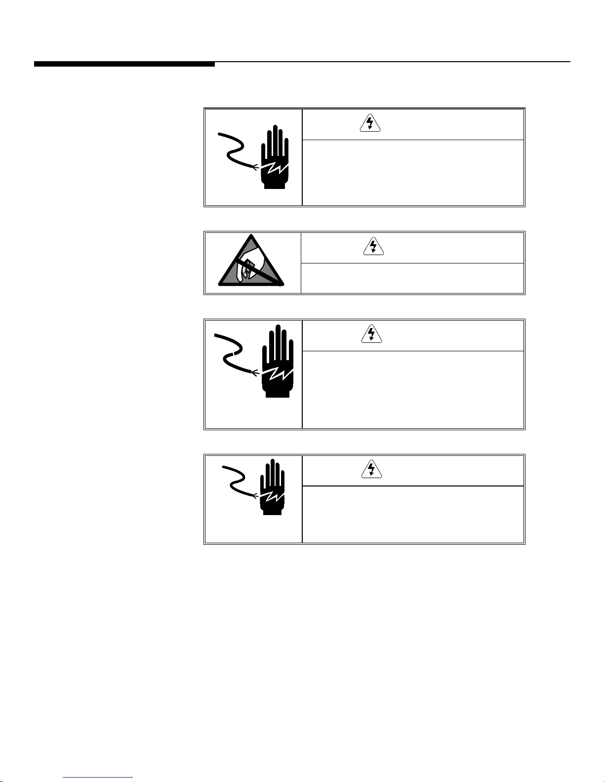
PRECAUTIONS
READ this manual BEFORE
operating or servicing this
equipment.
FOLLOW these instructions
carefully.
SAVE this manual for future
reference.
DO NOT allow untrained
personnel to operate, clean,
inspect, maintain, service, or
tamper with this equipment.
ALWAYS DISCONNECT this
equipment from the power
source before cleaning or
performing maintenance.
CALL METTLER TOLEDO for parts,
information, and service.
WARNING
DISCONNECT ALL POWER TO THIS UNIT BEFORE
INSTALLING, SERVICING, CLEANING, OR
REMOVING THE FUSE. FAILURE TO DO SO COULD
RESULT IN BODILY HARM AND/OR PROPERTY
DAMAGE.
CAUTION
OBSERVE PRECAUTIONS FOR HANDLING
ELECTROSTATIC SENSITIVE DEVICES.
WARNING
ONLY PERMIT QUALIFIED PERSONNEL TO
SERVICE THIS EQUIPMENT. EXERCISE CARE
WHEN MAKING CHECKS, TESTS AND
ADJUSTMENTS THAT MUST BE MADE WITH
POWER ON. FAILING TO OBSERVE THESE
PRECAUTIONS CAN RESULT IN BODILY HARM.
WARNING
FOR CONTINUED PROTECTION AGAINST SHOCK
HAZARD, CONNECT TO PROPERLY GROUNDED
OUTLET ONLY. DO NOT REMOVE THE GROUND
PRONG.
Page 7
IN ORDER TO INSTALL THE DIVISION 2 APPROVED
JAGXTREME PANEL-MOUNT OR HARSH TERMINAL
UTILIZING THE FACTORY MUTUAL APPROVAL, METTLER
TOLEDO CONTROL DRAWING 157043R MUST BE
FOLLOWED WITHOUT EXCEPTION. IN ORDER TO INSTALL
THE CATEGORY 3 JAGXTREME PANEL-MOUNT OR HARSH
TERMINAL UTILIZING THE KEMA APPROVAL THE KEMA
APPROVAL CERTIFICATE 02ATEX1023X AND ALL LOCAL
REGULATIONS MUST BE FOLLOWED WITHOUT EXCEPTION.
FAILURE TO DO SO COULD RESULT IN BODILY HARM
AND/OR PROPERTY DAMAGE. REFER TO THE JAGXTREME
DIVISION 2 AND ZONE 2/22 INSTALLATION GUIDE,
16088600A FOR ADDITIONAL INFORMATION.
WARNING
WARNING
EARLIER MODELS OF THE JAGXTREME TERMINAL THAT
ARE NOT MARKED (FACTORY-LABELED) AS DIVISION 2
OR EUROPEAN CATEGORY 3 APPROVED MUST NOT BE
INSTALLED IN A DIVISION 2 OR ZONE 2/22
ENVIRONMENT.
IF THE KEYBOARD, DISPLAY LENS OR ENCLOSURE IS
DAMAGED ON A DIVISION 2 APPROVED OR CATEGORY 3
MARKED JAGXTREME PANEL-MOUNT OR HARSH
TERMINAL THAT IS USED IN A DIVISION 2 OR ZONE 2/22
AREA, THE DEFECTIVE COMPONENT MUST BE REPAIRED
IMMEDIATELY. REMOVE AC POWER IMMEDIATELY AND
DO NOT REAPPLY AC POWER UNTIL THE DISPLAY LENS,
KEYBOARD OR ENCLOSURE HAS BEEN REPAIRED OR
REPLACED BY QUALIFIED SERVICE PERSONNEL. FAILURE
TO DO SO COULD RESULT IN BODILY HARM AND/OR
PROPERTY DAMAGE.
WARNING
Page 8

CONTENTS
1 Introduction .................................................................................................... 1-1
Model Identification .............................................................................................................1-1
References/Resources.................................................................................................1-2
Accessories...............................................................................................................1-2
Other Compatible Products..........................................................................................1-6
Software .............................................................................................................................1-7
Specifications ......................................................................................................................1-8
Display and Keypad...................................................................................................1-9
Physical Dimensions................................................................................................1-10
Power Requirements ................................................................................................1-15
Controller PCB.........................................................................................................1-15
Temperature and Humidity ........................................................................................1-16
Environmental Protection ..........................................................................................1-16
Standards Compliance........................................................................................................1-16
UL and cUL Listing...................................................................................................1-16
Weights and Measures Approvals ..............................................................................1-16
CE Conformity .........................................................................................................1-17
Conducted and Radiated Emissions (RFI)...................................................................1-17
Radio Frequency Interference Susceptibility..................................................................1-17
AC Power Line Voltage Variation ................................................................................1-17
2 Installation ..................................................................................................... 2-1
Overview.............................................................................................................................2-1
Unpacking and Inspection.....................................................................................................2-1
Standards Compliance..........................................................................................................2-2
UL and cUL Listing.....................................................................................................2-2
Environmental Considerations ...............................................................................................2-2
Temperature and Humidity ..........................................................................................2-2
Environmental Protection ............................................................................................2-2
Power Considerations...........................................................................................................2-2
Connecting to the JAGXTREME Terminal.................................................................................2-4
Connecting the Load Cell ............................................................................................2-4
Serial Port Connections Controller PCB .........................................................................2-9
Discrete Wiring........................................................................................................2-13
Optional Multifunction I/O PCB Serial and Discrete Connections .....................................2-15
Connecting the Power Cable......................................................................................2-17
Installing the General Purpose Model...................................................................................2-18
Installing the Panel Mount Model ........................................................................................2-20
Installing the Blind Panel Mount Unit ...................................................................................2-21
Installing the Harsh Environment Enclosure ..........................................................................2-22
Opening the Harsh Environment Terminal ...................................................................2-22
Mounting the Harsh Environment Terminal..................................................................2-23
Ethernet Connection...........................................................................................................2-24
JAGXTREME Terminal Jumper and Switch Settings................................................................2-25
Page 9

Controller PCB.........................................................................................................2-25
Analog Load Cell PCB ..............................................................................................2-26
Single Channel Analog Load Cell PCB ........................................................................2-27
Dual Channel Analog Load Cell PCB ..........................................................................2-28
Allen-Bradley RIO PCB..............................................................................................2-28
POWERCELL PCB ....................................................................................................2-29
MMR (IDNET) PCB...................................................................................................2-29
Multifunction I/O PCB ...............................................................................................2-30
Installing Options...............................................................................................................2-30
Apply Power ......................................................................................................................2-31
Power-up Sequence ...........................................................................................................2-32
Scale Build Determination...................................................................................................2-32
Minimum Increment Size for Bench and Portable Single DLC Scale Bases.......................2-32
Minimum Increment Size For Optional Analog Scale Input .............................................2-33
Sample Calculation..................................................................................................2-34
Seal the Enclosure - Weights and Measures Applications.......................................................2-34
Panel Mount Enclosure.............................................................................................2-34
General Purpose Enclosure .......................................................................................2-35
Harsh Environment Enclosure....................................................................................2-35
3 Programming and Calibration ........................................................................... 3-1
General Information .............................................................................................................3-1
Front Panel Display....................................................................................................3-1
Key Functions............................................................................................................3-2
Accessing Setup ........................................................................................................3-3
Navigating ................................................................................................................3-4
Audible Messages......................................................................................................3-5
Reset to Factory.........................................................................................................3-5
Configuring Terminals With Multiple Scales and a Summing Scale...................................3-6
Alibi Memory.............................................................................................................3-7
Program Block Overview.......................................................................................................3-8
Scale Interface Program Block...............................................................................................3-9
1. Market Sub-block.................................................................................................3-10
2. Scale Type Sub-block...........................................................................................3-10
3. Calibration Unit Sub-block.....................................................................................3-12
4. Capacity Sub-block..............................................................................................3-12
5. Increment Size Sub-block......................................................................................3-13
6. Shift Adjustment Sub-block....................................................................................3-14
7. Linearity Correction Sub-block ...............................................................................3-14
8. Calibration Sub-block...........................................................................................3-14
9. Zero Adjustment Sub-block....................................................................................3-16
10. Span Adjustment Sub-block.................................................................................3-16
11. Scale Test Sub-block.........................................................................................3-16
12. Add in Sum Sub-block........................................................................................3-16
13. Gravity Adjustment Sub-block..............................................................................3-17
14. Reset to Factory Sub-block..................................................................................3-17
Using the JAGXTREME with IDNET Bases .............................................................................3-17
Service Mode for IDNET Bases...................................................................................3-17
Page 10

JAGXTREME IDNET Calibration procedure....................................................................3-18
NATION Sub-block ...................................................................................................3-24
RESET Sub-block .....................................................................................................3-24
SCALE PARAMETERS Sub-block .................................................................................3-25
LINEARITY Sub-block................................................................................................3-25
CALIBRATION Sub-block ...........................................................................................3-26
SAVE PARAMETERS Program Sub-block......................................................................3-26
RETURN Sub-block...................................................................................................3-26
Application Environment Program Block ...............................................................................3-27
1. Character Set Sub-block........................................................................................3-28
2. Language Sub-block ............................................................................................3-28
3. Keyboard Type Sub-block .....................................................................................3-28
4. Scale ID Sub-block...............................................................................................3-28
5. Time and Date Sub-block......................................................................................3-29
6. Alternate Weight Units Sub-block............................................................................3-30
7. Power Up Operation Sub-block ..............................................................................3-31
8. Tare Operation Sub-block......................................................................................3-32
9a. Zero Operation Sub-block....................................................................................3-34
9b. Zero Operation Sub-block for IDNET Bases ............................................................3-35
10a. Stability Detect Sub-block..................................................................................3-35
10b. Stability Detect Sub-block for IDNET Bases ..........................................................3-35
11. Beeper Operation Sub-block ................................................................................3-36
12. Inhibit Memory Sub-Block...................................................................................3-36
13. Application Type Sub-block .................................................................................3-36
14. Vibration Rejection Sub-block ..............................................................................3-37
14a. Vibration Rejection Sub-block for IDNET ..............................................................3-38
Serial Interface Program Block ............................................................................................3-39
1. Configure Port Sub-block ......................................................................................3-40
2. Configure Template Sub-Block...............................................................................3-44
Configure Discrete Program Block .......................................................................................3-49
1. Discrete Inputs Sub-block .....................................................................................3-50
2. Discrete Outputs Sub-block ...................................................................................3-51
3. Assign Setpoints Sub-block ...................................................................................3-52
Configure Memory Program Block........................................................................................3-53
1. Configure Literals Sub-block..................................................................................3-53
2. Configure Prompts Sub-block ................................................................................3-54
3. Configure Consecutive Numbering Sub-block ..........................................................3-55
4. Alibi Memory.......................................................................................................3-56
Configure JagBASIC Program Block.....................................................................................3-57
1. Password Sub-block ............................................................................................3-58
2. Keyboard Sub-block.............................................................................................3-58
3. Display Sub-block................................................................................................3-58
4. Auto Start Sub-block.............................................................................................3-59
5. Manual Start Sub-block ........................................................................................3-59
6. LPRINT Port.........................................................................................................3-59
7. Send RAM Files Sub-block ....................................................................................3-59
8. Initialize RAM Disk Sub-block ................................................................................3-60
9. Password Maintenance Sub-block .........................................................................3-60
Configure Network Program Block .......................................................................................3-61
Network Overview ..............................................................................................................3-62
Page 11

General Networking Considerations .....................................................................................3-63
IP addresses ...........................................................................................................3-63
Clustering JAGXTREME Terminals ........................................................................................3-64
1. Ethernet Sub-block...............................................................................................3-68
2. Name-Password Sub-block...................................................................................3-68
3. Cluster IP Sub-block.............................................................................................3-69
4. PC Data Access (Reserved for Future Use) ..............................................................3-69
5. Email .................................................................................................................3-69
6. Web Server Sub-block ..........................................................................................3-70
7. FTP Server Sub-block ...........................................................................................3-70
8. PLC SP Control Sub-block.....................................................................................3-70
Configure Diagnostics Program Block ..................................................................................3-71
1. Memory Test Sub-block ........................................................................................3-72
2. Display Test Sub-block.........................................................................................3-72
3. Keyboard Test Sub-block ......................................................................................3-72
4. Scale Test Sub-block............................................................................................3-73
5. Serial Test Sub-block............................................................................................3-76
6. Parallel I/O Test Sub-block....................................................................................3-77
7. Network Test Sub-block ........................................................................................3-78
8. Ethernet Send BRAM Sub-block..............................................................................3-78
9. Zmodem Send BRAM Sub-Block ............................................................................3-79
10. Print Setup Sub-block .........................................................................................3-79
11. Reset to Factory Sub-block..................................................................................3-80
Configure Maintenance Program Block.................................................................................3-81
1. Calibration Management Sub-block........................................................................3-82
2. Calib Chk Parms Sub-block ..................................................................................3-83
3. Calib Mon Parms Sub-block..................................................................................3-84
Predictive Failure (Only for RAAD Box and POWERCELL Platforms) Sub-block.................3-86
Calibrate Check Sub-block ........................................................................................3-88
Maintenance Reports Sub-block.................................................................................3-89
Network Stats Sub-block...........................................................................................3-89
Reset to Factory.......................................................................................................3-89
Options Program Block .......................................................................................................3-90
4 Using the Web Server ...................................................................................... 4-1
System Requirements...........................................................................................................4-1
Setup..................................................................................................................................4-1
Operating Modes .................................................................................................................4-2
Navigation Bar Menu............................................................................................................4-2
Page 12

5 The Optional JagMAX Application Software........................................................ 5-1
Application Setup.................................................................................................................5-1
Starting the Application...............................................................................................5-1
Entering Application Setup...........................................................................................5-2
Moving Through Application Setup ...............................................................................5-2
General Setup............................................................................................................5-3
Weigh Mode Setup.....................................................................................................5-5
Re-Weigh Mode Setup................................................................................................5-6
Double Mode Setup....................................................................................................5-7
Triple Mode Setup ......................................................................................................5-7
Moving Van Mode Setup.............................................................................................5-8
ID Mode Setup...........................................................................................................5-8
Send Setup File........................................................................................................5-10
Print Setup ..............................................................................................................5-10
Transaction Report .............................................................................................................5-10
In-Process Report ..............................................................................................................5-11
Accumulation Report ..........................................................................................................5-12
End Program .....................................................................................................................5-13
Printing .............................................................................................................................5-13
6 Installing and Using JAGXFILES ........................................................................ 6-1
Hardware and Software Requirements ...................................................................................6-1
Installing JAGXFILES ............................................................................................................6-1
Browser and JAGXTREME Setup ............................................................................................6-1
Starting JAGXFILES ..............................................................................................................6-2
Configuring JAGXFILES on Your PC ..............................................................................6-2
Creating a Configuration File.................................................................................................6-2
Configuring Option Boards..........................................................................................6-3
Menu Items.........................................................................................................................6-4
File.....................................................................................................................................6-4
Open........................................................................................................................6-5
Save ........................................................................................................................6-6
Restore.....................................................................................................................6-7
Backup.....................................................................................................................6-8
All Other Menu Items ..................................................................................................6-8
Shutting Down JAGXFILES.....................................................................................................6-8
7 Service and Maintenance ................................................................................. 7-1
Tools and Supplies...............................................................................................................7-1
Cleaning and Regular Maintenance .......................................................................................7-1
Troubleshooting ...................................................................................................................7-1
Status Lights .............................................................................................................7-2
Error Codes and Actions .......................................................................................................7-2
Page 13

Diagnostic Tests ................................................................................................................7-18
AC Power Test .........................................................................................................7-18
Voltage Test ............................................................................................................7-18
Backup Battery Test..................................................................................................7-20
Ground Test ............................................................................................................7-20
External Equipment Test............................................................................................7-20
Internal Testing........................................................................................................7-21
20 mA /RS-232 Printer Tests.....................................................................................7-21
Replacing the Power Supply................................................................................................7-22
Replacing the Battery Back-up ............................................................................................7-23
8 Parts and Accessories ..................................................................................... 8-1
Panel Mount Parts ...............................................................................................................8-2
General Purpose Parts (Front View).......................................................................................8-4
General Purpose Parts (Rear View) .......................................................................................8-6
Harsh Environment Parts ......................................................................................................8-7
Line Cord Assemblies...........................................................................................................8-9
Controller PCB...................................................................................................................8-10
Analog Load Cell PCB ........................................................................................................8-11
Dual Analog Load Cell PCB.................................................................................................8-12
Power Supply ....................................................................................................................8-13
Allen-Bradley RIO Option ....................................................................................................8-14
CIP Interface Card .............................................................................................................8-15
PROFIBUS Option...............................................................................................................8-15
MODBUS Plus PCB.............................................................................................................8-16
Dual Analog Output Option..................................................................................................8-17
POWERCELL PCB...............................................................................................................8-18
Multifunction PCB ..............................................................................................................8-19
IDNET PCB ........................................................................................................................8-20
Optional Accessories..........................................................................................................8-21
Optional Panels .................................................................................................................8-22
Recommended Spare Parts.................................................................................................8-22
9 Appendices..................................................................................................... 9-1
Appendix 1: Serial Interface Reference...................................................................................9-1
Hardware Connections ...............................................................................................9-2
Output Modes and Formats.........................................................................................9-3
Standard Status Bytes A, B, and C................................................................................9-4
4-Setpoint Status Bytes A, B, and C..............................................................................9-5
Multi Cont 1 ..............................................................................................................9-6
Multi Cont 2 ..............................................................................................................9-6
Default Template Formats ...........................................................................................9-9
Input Modes............................................................................................................9-11
ASCII Characters ......................................................................................................9-16
Appendix 2: Discrete I/O Reference .....................................................................................9-20
Inputs.....................................................................................................................9-20
Page 14

Outputs ..................................................................................................................9-21
Appendix 3: Network Reference ..........................................................................................9-22
Keyboard/Display Sharing.........................................................................................9-22
Redirecting Serial Output...........................................................................................9-23
A-B RIO / PROFIBUS / MODBUS+ Option Sharing .........................................................9-24
Internet Explorer Proxy Server Setup............................................................................9-24
Appendix 4: Loading JAGXTREME Software ..........................................................................9-25
Using E_FLASH........................................................................................................9-25
E-FLASH Serial.........................................................................................................9-26
E-FLASH Ethernet .....................................................................................................9-27
FLASHPRO ..............................................................................................................9-27
Appendix 5: JAGXTREME Master Reset and Default Values....................................................9-29
Appendix 6: Gravity Factors ................................................................................................9-35
Appendix 7: Multiple Range/Multi-Interval Operation .............................................................9-36
Multiple Range Operation..........................................................................................9-36
Multi-Interval Operation.............................................................................................9-37
Appendix 8: Market Destination (Finish) Codes ....................................................................9-38
Page 15
1 Introduction
Model Identification
The JAGXTREME® Internet-enabled scale terminal is designed to help companies provide
cost-effective, flexible methods of production while maximizing engineering time and
effort. It offers connectivity to all METTLER TOLEDO technologies, as well as open
connectivity to the leading industry technologies, to facilitate communication and data
exchange with companies’ control, manufacturing execution, and enterprise systems.
The JAGXTREME terminal is available with various operator interfaces and enclosure
types, as well as with the optional JAGXTREME operator interface and optional JAGMAX
truck scale software. (Special instructions for programming the optional JAGMAX truck
scale software are included in this manual. Separate documentation is available for the
JAGXTREME operator interface). Please refer to the following Factory Number Reference
chart to identify the JAGXTREME terminal with which you will be working. A detailed
description of each designation is given to help you determine the specifications for
each model. A brief description of the optional accessories appears on the next page.
If you are upgrading an existing METTLER TOLEDO JAGUAR
JAGXTREME terminal, refer to the instructions provided with your upgrade kit.
Chapter 1: Introduction
Model Identification
®
terminal to a new
For users of the JAGXTREME terminal’s predecessor, METTLER TOLEDO’s JAGUAR
terminal, please pay special attention to the programming and calibration section.
Programming and calibration of the JAGXTREME terminal can be performed via the
embedded web server as well as through the front panel of the unit.
FACTORY NUMBER REFERENCE CHART
JAGXTREME TERMINAL MODEL CONFIGURATION
JX XX X X X X XXX
Terminal Enclosure
Display
JAGXTREME
Terminal
PB=Panel, Blind
PA=Panel, A/N
GA=General
Purpose A/N
HA=Harsh, A/N
Slot #1
Accessory
0=Cover Plate
1=Analog Scale
2=RE* Analog Scale
3=POWERCELL
4=IDNET
A=Dual Analog Scale
B=Dual RE* Analog Scale
®
Slot #2
Accessory
0=Cover Plate
1=Analog Scale
2= RE*Analog Scale
3=POWERCELL
4=IDNET
7=Multifunction I/O
A=Dual Analog Scale
B=Dual RE* Analog Scale
Slot #3
Accessory
0=Cover Plate
5=Modbus Plus
6=Allen Bradley RIO
7=Multi-function I/O
8=Dual Channel
Analog Output
9=PROFIBUS
C= CIP Interface**
Application
Software
0=Standard
JagBASIC
(included)
2 = JAGMAX™
Destination
Market
000=USA
See the Market
Codes in the
Appendix for
additional
destination
codes
*RE – Reduced Excitation. JAGXTREME terminals with harsh environment enclosures are not approved for use in hazardous areas.
As an example, the factory number JXPB-1002-000 denotes a JAGXTREME blind
panel-mount terminal with analog scale card and JAGMAX software for use in the USA.
Note: To order a JAGXTREME operator interface, you must use a separate model
number. Consult your METTLER TOLEDO representative or the JAGXTREME Operator
Interface documentation.
** Note: CIP connot be used with JXGA models.
(02/05)
1-1
Page 16

METTLER TOLEDO JAGXTREME Terminal Technical Manual
References/Resources
This manual provides information for configuring and serving the JAGXTREME terminal.
For information on installing the terminal, please refer to the Installation Guide that
accompanies the terminal. An electronic copy is also included on the documentation
CD-ROM that accompanies the unit. The CD-ROM includes the following resources:
• JAGXTREME Terminal Installation Guide
• JAGXTREME Terminal User's Guide
• JAGXTREME Terminal Technical Manual
• JAGXTREME Operator Interface Installation Guide
• JAGXTREME Operator Interface Technical Manual
• XTREMEBUILDER Software (with on-line help and programmer's reference guide)
®
• JagBASIC
• JAGXTREME PLC Analog Output Interfaces Technical Manual
• CIP Interface Technical Manual
• JAGMAX Application Software User's Guide
• JAGMAX Application Software Printer Templates Guide
Programmer's Guide
Accessories
• JAGXFILES™ (utility)
• Eflash (utility)
For additional information, contact your authorized METTLER TOLEDO representative or
http://www.mt.com.
go to:
A number of accessories are available for use with the JAGXTREME terminal. The model
configurator designation number appears in parentheses. Please contact your
authorized METTLER TOLEDO representative for more information.
Cover Plate (0)
This thin metal plate is used to cover the opening in the back of the regular or blind
chassis panel-mount terminal if an optional PCB is not installed at this location.
Analog Scale (1)
This option is required when interfacing analog-type load cells. A 15-volt excitation
voltage is used to power up to 16 350-ohm load cells from one analog PCB. A jumper
is provided to select operation with 2 mV/V or 3 mV/V load cells. The JAGXTREME
terminal will operate with load cells of impedances other than 350 ohms or other mV/V
specifications, but the total scale resistance must not be less than 22 ohms. A quiet
analog signal section, combined with a proprietary analog-to-digital converter and
coprocessor implementing METTLER TOLEDO TraxDSP
vibration rejection performance unequaled in the industry.
®
filters, provides weighing and
1-2
(02/05)
The zero temperature coefficient is 0.15 µV/degree C. The span temperature coefficient is
6 ppm/degree C. When using this option, the display update rate is limited to 10
updates per second. The actual A/D conversion rate exceeds 300 cycles per second.
This high-speed process allows the terminal to filter out noise while providing a weight
update rate of up to 50 updates per second for setpoint control and other functions.
Page 17

Chapter 1: Introduction
Model Identification
Each analog scale option board has a removable EEPROM that stores calibration
parameters for the scale. If an EEPROM is transferred to another board, all calibration
parameters transfer. A detachable seven-position terminal strip is used to terminate the
analog load cell cable on the rear of the PCB. Signal, excitation, sense, and shield
connections are provided with easy-to-read descriptions. Two LEDs are visible through
holes in the rear panel of the PCB to indicate the status of the analog PCB.
Reduced Excitation Analog Scale (2)
This option, when used with a protective load cell barrier, allows operation of the
JAGXTREME terminal with analog load cells located in an area classified as hazardous
by the National Electrical Code.
Division 2 or Category 3 approved terminal. The excitation voltage is lowered to 5 volts
for this option. The standard JAGXTREME terminal cannot be located inside a Division 1
or Zone 0/1 hazardous area
available from METTLER TOLEDO for applications which require the terminal to be
located inside a Division 1 or Zone 0/1 classified area.
The zero temperature coefficient is 0.15 µV/degree C. The span temperature coefficient is
6 ppm/degree C. When using this option, the display update rate is limited to 10
updates per second. The actual A/D conversion rate exceeds 300 cycles per second.
This high-speed process allows the terminal to filter out noise while providing a weight
update rate of up to 50 updates per second for setpoint control and other functions.
This option is required if the terminal is to be used as a
without special precautions. Purged enclosures are
Note: If a single IDNET card
is installed, it has to be
designated as Scale 1.
Each option board has a removable EEPROM that stores calibration parameters for the
scale. If an EEPROM is transferred to another board, all calibration parameters transfer
as well. A detachable seven-position terminal strip is used to terminate the analog load
cell cable on the rear of the PCB. Signal, excitation, sense, and shield connections are
provided, each with an easy-to-read description. Two LEDs are visible through holes in
the rear panel of the PCB to indicate its operating status.
POWERCELL (3)
The POWERCELL interface must be used when the JAGXTREME terminal is used with a
METTLER TOLEDO POWERCELL load cell system or RAAD box(es). It supports up
to a total of 24 DigiTOL POWERCELLs or six RAAD boxes. An external power supply is
needed when using more than 14 POWERCELLs or three RAAD boxes. METTLER
TOLEDO also offers intrinsically safe barriers for use with POWERCELL
systems located in hazardous areas. Please contact your METTLER TOLEDO
representative for more information about applications in hazardous environments.
IDNET (4)
The IDNET interface allows you to interface a METTLER TOLEDO multi-range base or lab
balance with IDNET option with the JAGXTREME terminal. When utilizing this interface,
the terminal acts as a “front end” for the base. Setup and calibration of the base is
identical to the procedure used by the ID family of indicators. Scale-related information
is stored in the scale base as well as the terminal, allowing its access by external
devices such as a PLC.
*Only one can be loaded
into the JAGXTREME
terminal.
Modbus Plus* (5)
The Modbus Plus interface enables the terminal to directly interface with Modbus Plus
devices such as PLCs manufactured by MODICON. The JAGXTREME terminal interface
acts as a single Modbus Plus node, which can support up to four scales, and has been
fully certified by the Modicon Test Center.
(02/05)
1-3
Page 18

METTLER TOLEDO JAGXTREME Terminal Technical Manual
Allen-Bradley RIO* (6)
This option allows the JAGXTREME terminal to exchange data with an Allen-Bradley PLC
like a remote 1771 module on the Allen-Bradley remote I/O. A direct connection to an
Allen-Bradley controller is possible via this “blue hose” connection. If the terminal has
two or more scales installed, all share the same RIO option board. If multiple terminals
are combined in a “cluster” using Ethernet, up to four scales can share the RIO option.
Each scale requires one-quarter rack of RIO address space. JAGXTREME terminals
support quarter rack addressing.
JAGXTREME terminals support discrete and block transfer modes of data interface. Both
are bi-directional. Discrete mode is used for data, status, and command exchange.
Block transfer allows more extensive data exchange and allows the PLC to write
messages to the terminal’s lower alphanumeric display. Connection to the RIO option is
made via a detachable three-position terminal strip on the rear of the RIO option.
Multifunction I/O (7)
The Multifunction PCB option expands the number of serial and discrete input and
output ports supported by the JAGXTREME terminal. The Multifunction PCB adds two
serial ports. COM3 can be used for RS-232 communications. COM4 can be used for
RS-232 or RS-422/RS-485 communications. COM4 can be used for a single DigiTOL
or UltraRes understructure interface. The Multifunction PCB adds eight programmable
discrete inputs (PAR 3). Eight programmable discrete outputs (PAR 4). PAR 3 and PAR
4 assignments are user-configurable.
*Only one can be loaded
into the JAGXTREME
terminal.
Dual Channel Analog Output* (8)
The Analog Output module provides two channels of analog output, one for each of up
to two scales connected to the terminal. The channels may be selected to provide either
a 0 to 10 V or a 4 to 20 mA analog output signal. The output is the result of a 16-bit
digital to analog conversion.
PROFIBUS Interface* (9)
The JAGXTREME terminal with the PROFIBUS interface module is a fully L2-DP
compliant device which can be used with a wide range of PROFIBUS compatible
devices. This module provides the process control engineer with the ability to access
weight information, status of the scale, and to download a setpoint or tare weight. The
Profibus option has been fully certified by the Siemens Profibus Test Center.
Dual Analog Scale (A)
This option is required when interfacing analog-type load cells. A 15-volt excitation
voltage is used to power up to 16 350-ohm load cells from one analog channel. The
dual channel card can support a maximum of 20 load cells and up to four analog
platforms. A jumper is provided to select operation with either 2mV/V or 3mV/V load
cells. The terminal will operate with load cells of impedances other than 350 ohms or
other mV/V specifications, but the total scale resistance must not be less than 22 ohms.
A quiet analog signal section, combined with an analog-to-digital converter and coprocessor that use METTLER TOLEDO TraxDSP filters, provides weighing and vibration
rejection performance unequaled in the industry. The zero temperature coefficient is 0.15
uV/degree C. The span temperature coefficient is 6 ppm/degree C.
1-4
(02/05)
When using this option, the display update rate is limited to 10 updates per second.
The actual A/D conversion rate exceeds 300 cycles per second. The high-speed process
allows the terminal to filter out noise while providing a weight update rate up to 50
updates per second for setpoint control and other functions.
Page 19

Chapter 1: Introduction
Model Identification
The dual channel analog scale option board has a removable EEPROM for each scale
channel that stores calibration parameters for that scale channel. If an EEPROM is
transferred to another board, all calibration parameters transfer as well.
A detachable seven-position terminal strip is used to terminate each analog load cell
cable on the rear of the PCB. Signal, excitation, sense, and shield connections are
provided with easy-to-read descriptions. Two LEDs are visible through holes in the rear
panel of the PCB to indicate the status of the Analog PCB. The terminal supports up to
two dual analog scale cards.
Reduced Excitation Dual Analog Scale (B)
This option is used with a protective load cell barrier to permit operation of a
JAGXTREME terminal with analog load cells located in an area classified as hazardous
by the National Electrical Code. It can support up to four analog platforms. The
excitation voltage is lowered to 5 volts. A METTLER TOLEDO Reduced Excitation module
is required for these applications. The standard terminal cannot be located inside the
hazardous area as is. Purged enclosures are available from METTLER TOLEDO if the
terminal must be located inside a hazardous area. The Reduced Excitation module can
only support up to 12 analog load cells or a total resistance of 58 ohms. Jumpers are
provided to select operation with 2mV/V or 3mV/V load cells. The terminal will operate
with load cells of impedances other than 350 ohms or other mV/V specifications, but
the total scale resistance must not be less than 22 ohms.
The zero temperature coefficient is 0.15 uV/degree C. The span temperature coefficient is
6 ppm/degree C. When using this option, the display update rate is limited to 10
updates per second. The actual A/D conversion rate exceeds 300 cycles per second.
The high-speed process allows the terminal to filter out noise and still provide a weight
update rate up to 50 updates per second for setpoint control and other scale functions.
The dual channel analog scale option board has a removable EEPROM for each scale
channel that stores calibration parameters for that scale channel. If an EEPROM is
transferred to another board, all calibration parameters transfer as well.
A detachable seven-position terminal strip is used to terminate each analog load cell
cable on the rear of this PCB. Signal, excitation, sense, and shield connections are
provided, each with an easy-to-read description. Two LEDs are visible through holes in
the rear panel of this PCB to indicate the status of the Analog PCB. The JAGXTREME
terminal will support one or two Reduced Excitation dual analog scale cards.
**CIP Network Interface (ControlNET) (C)
The CIP network interface enables the JAGXTREME terminal to directly interface with a
CIP network (ControlNet or Ethernet/IP). The JAGXTREME terminal interface supports
both the ControlNet and Ethernet/IP network protocol utilizing the following types of
message:
• Class 1, connected, scheduled messaging
• Connected, unscheduled, explicit messaging, using ControlNet Object,
Instance, and Attributes ID’s.
** Note: CIP card cannot be used with JXGA models due to ControlNet connector size.
(02/05)
1-5
Page 20

METTLER TOLEDO JAGXTREME Terminal Technical Manual
Other Compatible Products
RAAD Box
METTLER TOLEDO’s RAAD (Remote Addressable Analog to Digital) junction box is used
to transform conventional strain gauge load cell systems into advanced sensor
networks. Instead of analyzing the combined signal from every load cell in the system,
the RAAD box embeds intelligence into each individual load cell, enabling you to
analyze your system at the lowest level. When used with the JAGXTREME terminal, the
RAAD box can detect failures immediately to help guard against costly downtime or
product waste. The RAAD box can also be used with METTLER TOLEDO’s COUGAR
terminal.
8624 Remote Display
The METTLER TOLEDO 8624 Remote Display allows an operator to remotely view
weight and status with the JAGXTREME terminal. The 8624 connects to the JAGXTREME
serial port and can be located remote from the JAGXTREME chassis.
8618 Scoreboard
The METTLER TOLEDO 8618 scoreboard allows an operator to remotely view weight
with the JAGXTREME terminal. The 8618 connects to one of the JAGXTREME serial ports
and can be located remote form the JAGXTREME chassis.
Printers
METTLER TOLEDO offers a family of reliable printers well suited for industrial
applications. The printers connect to one of the JAGXTREME serial ports and can be
located remote from the JAGXTREME chassis.
DNB Module
The METTLER TOLEDO DNB module (DeviceNet bridge) allows a PLC to access weigh
and status with the JAGXTREME terminal. The DNB module connects to the JAGXTREME
serial port and can be located remote from the JAGXTREME chassis.
JAGXTREME Operator Interface (JXOI)
The JXOI is an Ethernet-enabled graphic terminal with object-based programming. It is
available in pedestal and panel-mount versions (graphical display only) or a harsh
environment terminal version (comprised of a blind JAGXTREME terminal and a
graphical display in an enclosure.)
The JXOI features a 1/4 VGA, 240 x 320 pixels, STN color display. It uses a coldcathode fluorescent backlight (CCFL). The CCFL provides high contrast and easy
readability and is replaceable. The contrast is software-controlled and compensated for
temperature.
The JXOI comes equipped with one RS-232 serial port with an Ethernet port and a PS/2
keyboard port. It stores the firmware and the user application in a compressed format in
flash memory and then transfers them to RAM memory when the JXOI is powered on.
1-6
(02/05)
Page 21

Software
Chapter 1: Introduction
Software
JAGXTREME Operating System
The JAGXTREME operating system is available in four configurations. The configurations
define the language of the HTML web pages and are determined by the country finish
code of the terminal part number. The available configurations are:
English/Chinese
English/French
English/German
English/Spanish
JagBASIC
JagBASIC software is standard in the JAGXTREME terminal. JagBASIC is a tool for
customizing the JAGXTREME industrial scale terminal. JagBASIC programs reside along
side the standard JAGXTREME terminal program. The JagBASIC interpreter runs as a
separate task using the terminal’s multi-tasking operating system. This allows the
custom JagBASIC program to interact with the other JAGXTREME terminal tasks and
resources using the terminal’s exclusive shared memory design. For example, to
monitor a scale gross weight, the JagBASIC program relates a BASIC variable to the
terminal shared data variable for gross weight then uses the BASIC variable as desired.
All of the shared memory in the terminal may be accessed by the JagBASIC program
using this construct.
The high level of integration permits the programmer to exploit the standard functions in
the JAGXTREME terminal, making it easier to implement solid solutions in record time.
To print a standard ticket or report, a JagBASIC program can load data into a
JAGXTREME terminal shared data variable then print by using a standard template that
is designed in the terminal setup. Rather than monitoring setpoint coincidence in the
JagBASIC program, a standard setpoint shared data variable can be loaded in the
program then monitored by an associated JAGXTREME terminal scale task.
JAGMAX
The optional JAGMAX software enables the JAGXTREME terminal to be used in a truck
stop weigh station application. With the JAGMAX software, trucks can be weighed in Idle
Mode, Semi-Automatic Mode, and Automatic Mode.
(02/05)
1-7
Page 22

METTLER TOLEDO JAGXTREME Terminal Technical Manual
Specifications
Model General Purpose Panel Mount Panel Mount – Blind Chassis Harsh Environment/Harsh with
Dimensions
Construction
Mounting Options
Degree of
Protection
Ethernet
Connection
Attachable
Platforms
Display
Keypad
Interfaces
A/D Rate
Digital
Input/Output
Maintenance
Monitoring
Signal Processing
Power
Requirements
Setup
Scripting Language
Operating
Temperature
Storage
Temperature
Options
Approvals
10.05 in (255 mm) wide x
7.86 in (200 mm) high x 10.6
in (270 mm) deep
Column, desktop Panel Blind panel Wall, column
Designed to TYPE 4X standards Designed to TYPE 4X standards
10BASE-T. Uses crossover cable from RJ-45 Ethernet port on the back of the JAGXTREME terminal to a PC (point to-point connection) or
standard cable to connect to other equipment through a hub.
4 analog, 4 POWERCELL
®
up to 3 POWERCELLs, 2 analog and 2 POWERCELLs, 1 PC with 1 IDNET and 1 DigiTOL
Upper display: 7 segment 0.5" (13 mm); lower display: 16-character, 5 x 7 dot matrix display 0.25" (6 mm)
TraxEMT™ Embedded Maintenance Technician system for self-diagnosis and predictive failure analysis
Analog, Dual Analog, Analog Reduced Excitation, Dual Analog Reduced Excitation, Dual Analog Output, Modbus Plus, Profibus, A-B RIO,
Multifunction I/O, IDNet, POWERCELL, PCJagBASIC EDITOR, JAGMAX Truck Scale Software, HMI Pedestal or Panel, ControlNet/Ethernet IP
Class III and IIIL non-automatic weighing instruments as defined in the National Standards Commission, Document 100
10.05 in (255 mm) x 5.6 in
(140 mm) at front of terminal
9.5 in (240 mm) x 4.91 in
(125 mm) at the rear
8.03 in (210 mm) deep
Aluminum Stainless steel
(front panel)
,
2 IDNET, 2 DigiTOL®, 1 single analog and 1 single IDNET, 1 single analog and 1 DigiTOL, 1 single analog and
4 x 5 matrix tactile-feel keypad with 0-9, letters A-Z, and function keys
85 to 264 VAC with a line frequency of 47 to 63 Hz
Via embedded web server, with the front keypad or using the JagXFILES tool box.
14° F to 104° F (-10° C to 40° C) at 10% to 95% relative humidity, non-condensing
40° F to 140° F (-40° C to 60° C) at 10% to 95% relative humidity, non-condensing
90/384/EU – Non-automatic Balances and Scales
EN45501:1992 – Adopted European Standard
NTEP Certificate of Conformance No. 94-096A4
10,000 division rating and approval AM-5041
10.75 in (270 mm) x 4.91 in
(124 mm) at base
10.25 in (260 mm) x 3.91 in
(100 mm) c-c mounting
9.5 in (241 mm) x 5.00 in
(130 mm) chassis
Designed to TYPE 1 standards CERTIFIED TYPE 4, TYPE 12
Two vacuum fluorescent displays.
Ethernet, serial, discrete, PLC, analog
>300 per second
Maximum 12 in/12 out
TraxDSP
three-stage filtering
®
JagBASIC (standard)
CE Conformity
89/336/EU—EMC Directive
EN55022, 1998, Class A
Weights and Measures (US)
Class III or IIIL devices
Weights and Measures (Canada)
Weights and Measures (Australia)
Graphical Display
12.62 in (321 mm) x 9.56
(242.8) x 9.42 (239.3 mm)
1-8
(02/05)
Page 23
Display and Keypad
Chapter 1: Introduction
Specifications
Alphanumeric Display (xA)
The JAGXTREME terminal contains two vacuum fluorescent displays and a 4 × 5 matrix
tactile feel keypad in a diecast, zinc-aluminum alloy front housing.
The upper weight display is a seven-digit, seven-segment 0.5 in. (13 mm) high
vacuum fluorescent numeric display used to indicate weight values. Each of the seven
digits has a decimal point/comma and an annunciator associated with it. The
annunciators are used to indicate gross or net weights, a preset tare value, pound or
kilogram weights, the center of zero, and motion.
The lower display is a 16-character, 5×7 dot matrix, 0.25 in. (6 mm) high vacuum
fluorescent alphanumeric display. Each character has a period/comma and an
annunciator associated with it. This display is used to indicate tare, alternate weight
units, operator prompting, errors and other messages. The first 10 annunciators are
used to indicate which terminal number (1 through 6) and internal scale (A-D) are
currently displayed. The remainder indicates summation and weighing range.
The lens on both the general purpose and panel-mount models are polycarbonate with
hardcoating. The harsh environment model lens is polyester with hardcoating.
The keypad consists of a tactile-feel membrane switch covered with a polyester overlay.
Audible beeps sound when a key is depressed. The keypad contains the numbers 0 -9
and the letters A - Z. Other function keys include Escape, Memory, Tare, Select, Clear,
space, decimal point, Zero, Enter, and Function.
1-a: Display and keypad on panel-mount version of the JAGXTREME terminal
(02/05)
1-9
Page 24
METTLER TOLEDO JAGXTREME Terminal Technical Manual
Physical Dimensions
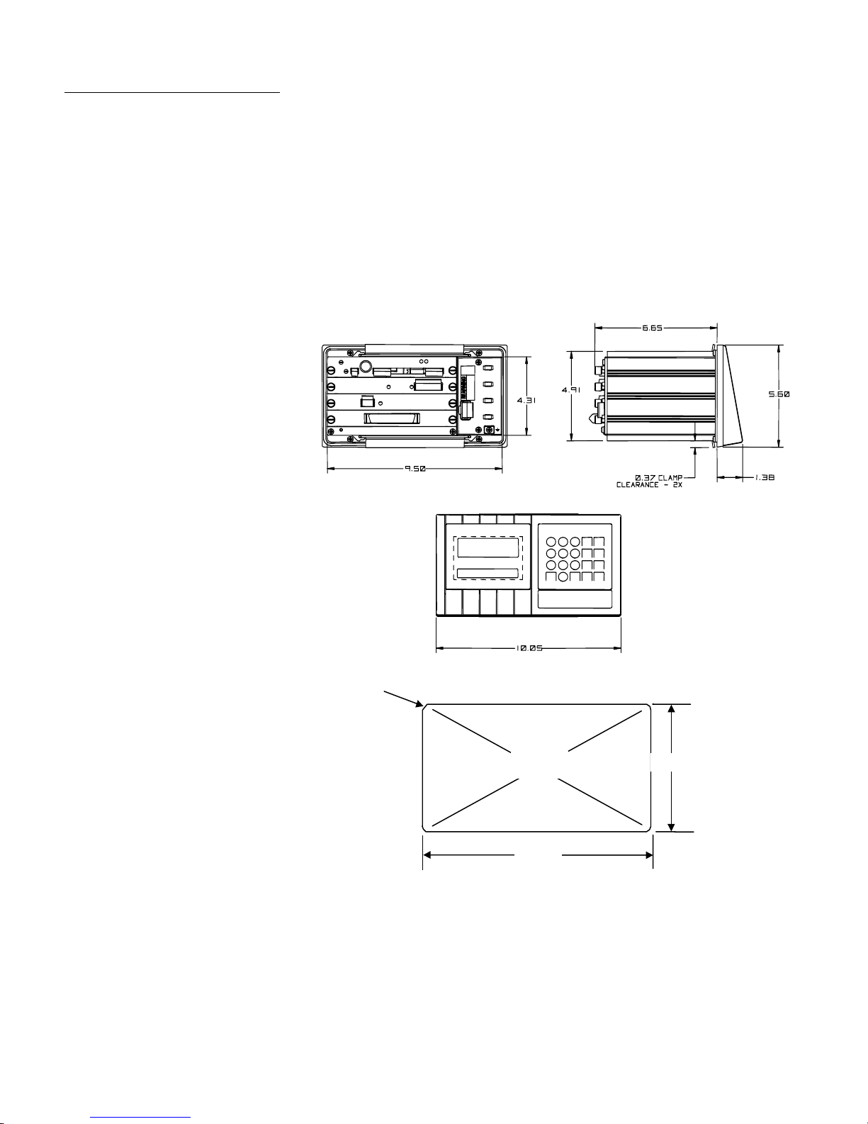
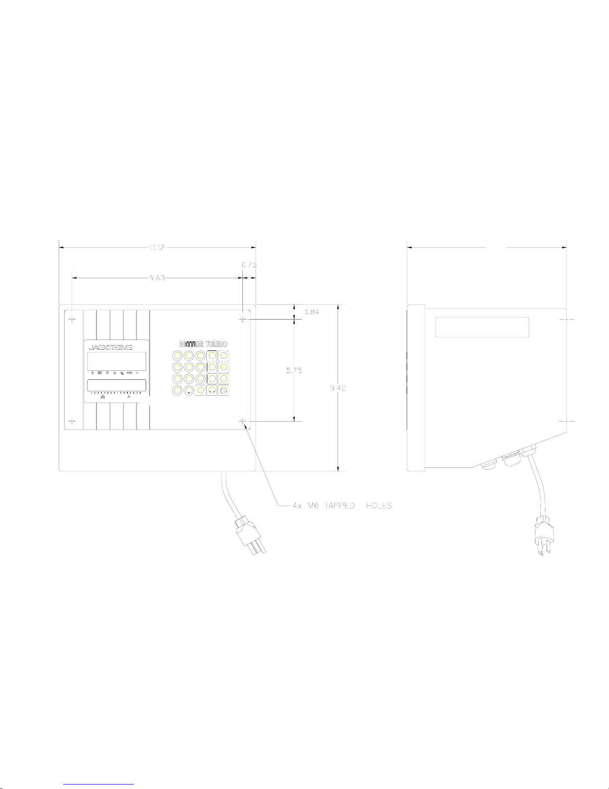
Panel Mount Enclosure—Alphanumeric (PA)
Two integral brackets are used to mount this unit through a flat panel. The front panel
and associated panel clamping mechanism are designed to provide a TYPE 4 seal and
accommodate a panel thickness from 16 to 11 gauge.
The panel-mount model measures:
• 10.05 in. (255 mm) × 5.6 in. (140 mm) at the front of the terminal
• 9.5 in. (240 mm) × 4.91 in. (125 mm) at the rear
• 8.03 in. (210 mm) deep
4XR 0.25±.01
OPEN
Abra
9.58±.06
5.12±.0
1-10
(02/05)
Figure 1-b: JAGXTREME Panel Mount Model and Cutout Dimensions
Page 25
Chapter 1: Introduction
Specifications
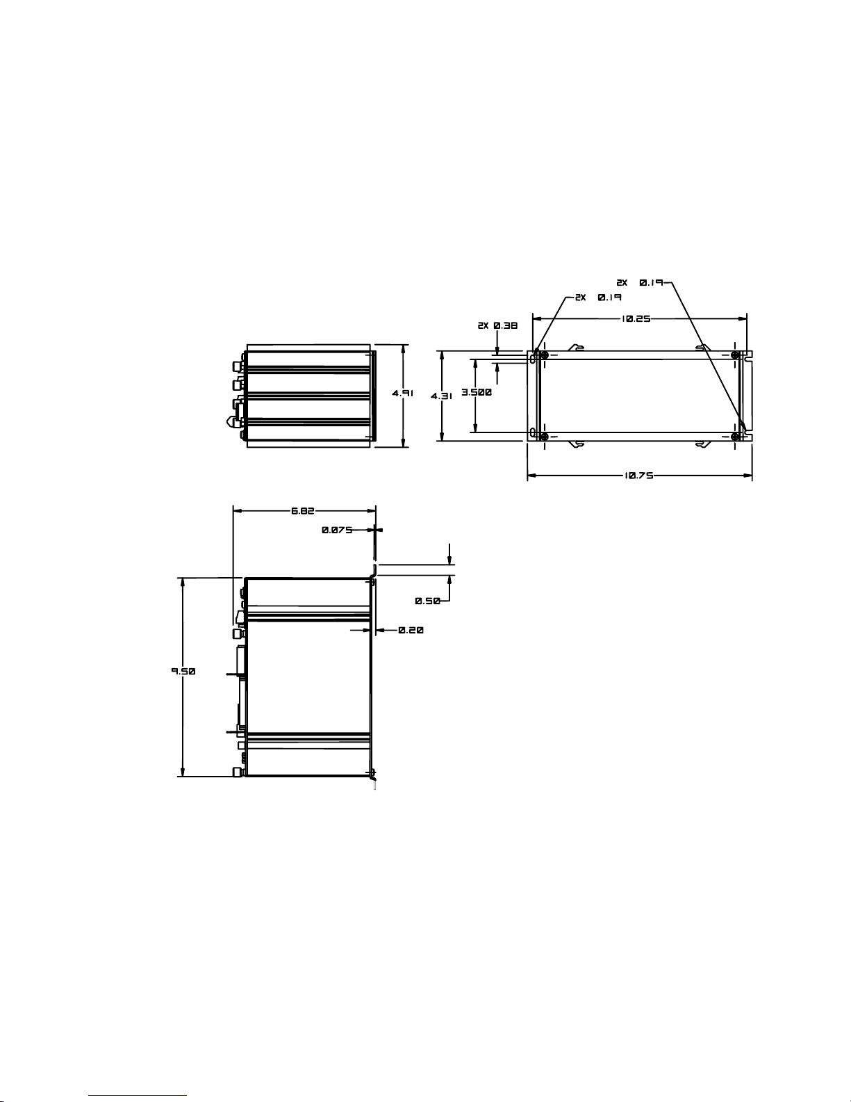
Panel Mount Enclosure—Blind Chassis (PB)
The front of the panel mount enclosure has a blank plate to cover the electronics and to
provide a method of mounting. There is no keyboard or display on the front of the unit.
This allows the terminal’s use as a “blind” terminal (installed behind a panel,) sharing
another JAGXTREME terminal’s keyboard and display via the Ethernet connection. The
terminal enclosure designed to TYPE 1 requirements with a “blind” front panel.
The blind chassis mount model measures:
10.75 in. (270 mm) × 4.91 in. (125 mm) at the base
10.25 in. (260 mm) × 3.91 in. (100 mm) c-c mounting
9.5 in. (241 mm) × 5.00 in. (130 mm) chassis
Figure 1-c: JAGXTREME Blind Chassis Model Dimensions
(02/05)
1-11
Page 26
METTLER TOLEDO JAGXTREME Terminal Technical Manual
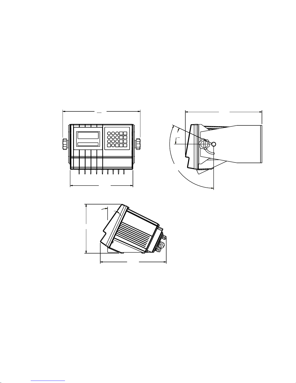
General Purpose Enclosure (GA)
This enclosure, which is designed to provide TYPE 4X protection, is a die-cast zincaluminum alloy with an aliphatic urethane powder-coated finish. The unit is designed
to sit on a flat surface or may be wall- or column-mounted with an accessory bracket kit
(0917-0209). The rear cover contains grip bushings to seal all cables entering the
enclosure.
The general-purpose JAGXTREME terminal model measures:
10.05 in. (255 mm) wide × 7.86 in. (200 mm) high x 10.6 in. (270 mm) deep
In figure 1-d, the top views show optional wall/column brackets (P/N 0917-0209).
7.85
12.45
10.05
39°
12.31
29°
°
115°
°
°
1-12
(02/05)
10.59
Figure 1-d: JAGXTREME General Purpose Model Dimensions
Page 27
NOTE: Units sold prior to
July, 2001 may have
different dimensions. Refer
to the previous revision of
the JAGXTREME Terminal
Technical Manual for
information.
Chapter 1: Introduction
Specifications
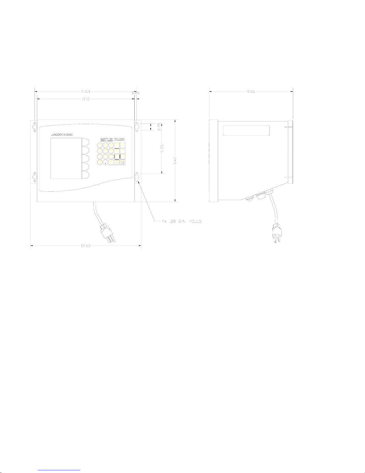
Harsh Environment Enclosure (HA)
The harsh environment enclosure is designed to provide TYPE 4 and TYPE 12 protection
and is intended for applications in which the terminal is exposed to high humidity, direct
washdown, or corrosive environments. It is constructed of 304L stainless steel and
meets all US FDA and comparable European requirements.
A full 4-slot JAGXTREME terminal chassis is mounted inside the enclosure. All field
wiring enters into the unit through cable seals that maintain the washdown protection of
the enclosure. The cable seals are located at the bottom rear of the unit. Two brackets
are provided for wall mount applications. An interface adapter (0917-0233) is
available for column mount applications.
The harsh environment unit measures: 12.62 in (321 mm) x 9.56 (242.8 mm) x
9.42 (239.3 mm)
9.56
* Shown with wall mount brackets
(included with enclosure) installed.
Figure 1-f: Harsh Environment Model Dimensions
(02/05)
1-13
Page 28
METTLER TOLEDO JAGXTREME Terminal Technical Manual
Harsh Environment Enclosure (JXHG)
The JXHG (harsh environment enclosure with graphic display) is comprised of a
JAGXTREME chassis and a graphical display housed in an enclosure.
Dimensions: 9.42 x 12.62” x 9.56" (239.3 x 321 x 242.8 mm)
Figure 1-g
1-14
(02/05)
Page 29

Power Requirements
Chapter 1: Introduction
Specifications
85 to 264 VAC with a line frequency of 47 to 63 Hz.
Power consumption -- 20 Watts maximum.
Power termination -- single three-position removable terminal strip.
The wire size range -- 12 to 16 AWG.
Note: The integrity of the power ground for equipment is important for both safety and
dependable operation of the JAGXTREME terminal and its associated scale bases. A
poor ground can result in an unsafe condition if an electrical short develops in the
equipment. A good ground connection is needed to assure extraneous electrical noise
pulses are minimized. It is important that equipment does not share power lines with
noise generating equipment like heavy load switching, motor starter circuits, RF thermal
heaters, inductive loads and the like.
To confirm ground integrity, a commercial branch circuit analyzer is recommended. This
instrument uses a high amperage pulse to check ground resistance. It measures the
voltage from the neutral wire to the ground connection and will provide an assessment
of the line loading. Instructions with the instrument give guidelines about limits that
assure good connections.
The power line for the JAGXTREME terminal must not be shared with equipment such as
motors, relays, or heaters that generate line noise. If adverse power conditions exist, a
dedicated power circuit or power line conditioner may be required.
Controller PCB
When a Division 2 approved JagXtreme is installed in an area classified as Division 2
or Zone 2/22, special AC wiring requirements must be met. See document 16088600A,
JagXtreme Panel Mount Division 2, Zone 2/22 Installation Guide.
Four discrete inputs (PAR1).
Four discrete outputs (PAR2)(5 to 30 volts DC).
The output current is 35 mA per discrete output up to 115 mA maximum total
current draw on the +5 Volts DC supply.
Inputs can be defined as clear (return to gross), tare, print, zero, and other keyboard
functions.
Outputs can be defined for coincidence setpoints or a variety of scale conditions.
The COM1 serial port can be either RS-232 or 20 mA current loop active transmit.
Both are available simultaneously.
The COM2 serial port can be either RS-232 or RS-422/RS-485. This port is also
used to support a DigiTOL or UltraRes scale interface.
Keyboard input is a standard 6-pin PS2 type mini DIN connection for a compatible
keyboard.
The Ethernet network connection uses a RJ45 connection.
Connections to the Controller PCB are made using four removable terminal strips.
The wire size range is 16 to 22 AWG.
The Controller PCB stores DigiTOL scale calibration parameters in its EEPROM. If
analog load cell scale(s) are installed, the calibration parameters for each scale are
stored in the EEPROM of the Analog PCB. IDNET calibration parameters are stored in
(02/05)
1-15
Page 30
METTLER TOLEDO JAGXTREME Terminal Technical Manual
the base. POWERCELL (or RAAD box) parameters are stored on the POWERCELL
PCB.
Temperature and Humidity
Operating temperature: 14 to 104ºF (-10 to 40ºC) at 10% to 95% humidity, non-
condensing.
Storage temperature: -40 to 140ºF (-40 to 60ºC) at 10% to 95% humidity,
noncondensing.
The optional analog PCB zero temperature coefficient is 0.15 µV/ºC. Span
temperature coefficient is 6 ppm/°C maximum.
Environmental Protection
When a Division 2 approved JagXtreme is installed in an area classified as Division 2
or Zone 2/22, special AC wiring requirements must be met. See document 16088600A,
JagXtreme Panel Mount Division 2, Zone 2/22 Installation Guide.
WARNING!
THE JAGXTREME TERMINAL IS NOT INTRINSICALLY SAFE! DO
NOT USE IN AREAS CLASSIFIED AS HAZARDOUS BY THE
NATIONAL ELECTRIC CODE (NEC) BECAUSE OF COMBUSTIBLE OR EXPLOSIVE ATMOSPHERES.
Standards Compliance
UL and cUL Listing
Weights and Measures
Approvals
The JAGXTREME terminal has been tested and complies with UL 1950 and CSA 22.2
No. 950-M89. The JAGXTREME terminal carries the UL and cUL labels.
United States
The JAGXTREME terminal meets or exceeds requirements for Class III or IIIL devices.
Certificate of Conformance No. 94-096A4 was issued under the National Type
Evaluation Program of the National Conference on Weights and Measures.
Canada
The JAGXTREME terminal meets or exceeds requirements for a 10,000 division rating
and approval AM-5041 has been issued by statutory authority of the Minister of
Industry, Science and Technology of Canada.
1-16
(02/05)
Australia
The JAGXTREME terminal meets or exceeds the requirements for Class III and IIIL nonautomatic weighing instruments as defined in the National Standards Commission,
Page 31

CE Conformity
Conducted and Radiated
Chapter 1: Introduction
Standards Compliance
Document 100. The National Standards Commission has approved the JAGXTREME
terminal for use with approved and compatible platforms.
Europe
The JAGXTREME terminal was submitted for approval to The Nederlands Meetindtituut
(NMi) in the Netherlands. After evaluation, the JAGXTREME terminal was found to meet
and/or exceed the requirements for a Class III weighing instrument. EC type approval
certificate TC2618 (Revision 5) was issued by the NMi in accordance to Council
Directive 90/384/EEC.
The JAGXTREME terminal conforms to the following European Union regulations:
90/384/EU—Non-automatic Balances and Scales
EN45501:1992—Adopted European Standard
89/336/EU—EMC Directive
EN55022:1998, Class A
Emissions (RFI)
The JAGXTREME terminal meets or exceeds FCC Part 15 for conducted and radiated
emissions requirements as a Class A digital device.
Radio Frequency
Interference Susceptibility
The JAGXTREME terminal meets US, Canadian, and European requirements for RFI
susceptibility as listed in the following table with a maximum of one display increment
of change when calibrated for recommended builds.
Radio Interference Frequency Field Strength
26-1000 MHz 3 volts/meter
AC Power Line Voltage
Variation
The JAGXTREME terminal meets NIST H-44, Canadian Gazette Part 1, and OIMLSP7/SP2 line voltage variation specifications as listed in the following table.
AC Power Line Voltages
Specification AC Line Voltage Line Frequency in Hz
Line Voltage Variation Minimum Nominal Maximum Minimum Nominal Maximum
NIST H-44
Canadian
OIML-SP7/SP2
100 120 130 59.5 60 60.5
108 120 132 58.8 60 61.2
102
187
204
120
220
264
132
242
264
58.8
49.0
49.0
60
50
50
61.2
51
51
(02/05)
1-17
Page 32

METTLER TOLEDO JAGXTREME Terminal Technical Manual
1-18
(02/05)
Page 33

Chapter 1: Introduction
Standards Compliance
For your notes
(02/05)
1-19
Page 34

2 Installation
Overview
The following information provides instructions for installing and wiring the JAGXTREME
terminal. This information is also found in the Installation Guide that accompanies the
unit. In addition, this chapter provides information on setting the terminal's jumper and
switch settings and on installing options.
Unpacking and
Inspection
1. If upon delivery the shipping container for the terminal appears damaged, check
for internal damage and file a freight claim with the carrier if required.
2. If the container is undamaged, unpack the terminal from its protective package
and inspect each component for damage.
Chapter 2: Installation
Overview
3. Verify that you have the correct package contents. To install the terminal, you
need the terminal, the screwdriver provided, and these instructions. You may
also need common hand tools, such as flat and Phillips head screwdrivers for
the general-purpose unit and a drill and wrenches for use with the harsh
environment unit. All other package contents should remain in the box.
Package contents for all JAGXTREME terminals include:
• JAGXTREME terminal • Screwdriver
• Installation Guide • Set of capacity labels
• Weights and Measures sealing
screws
• Mating connectors for the I/O port
• JAGXTREME CD-ROM with documentation
and utilities
Package contents for the panel mount and blind chassis JAGXTREME terminal
also include:
• Hardware kit (*)15411600A
Package contents for the harsh environment JAGXTREME terminal include:
• 2 stainless steel wall mount brackets
• 4 stainless steel bolts for attaching the wall mount brackets
• Hardware kit (*)15411500A
Package contents for the general purpose JAGXTREME terminal includes:
• Hardware kit (*)15411400A
(03/05)
2-1
Page 35

METTLER TOLEDO JAGXTREME Terminal Technical Manual
Standards Compliance
UL and cUL Listing
The JAGXTREME terminal has been tested and complies with UL 1950 and CSA 22.2
No. 950-M89. The JAGXTREME terminal carries the UL and cUL labels.
Environmental
Considerations
Temperature and Humidity
• Operating temperature: 14 to 104ºF (-10 to 40ºC) at 10% to 95% humidity, non-
condensing.
• Storage temperature: -40 to 140ºF (-40 to 60ºC) at 10% to 95% humidity, non-
condensing.
Environmental Protection
Power Considerations
The JAGXTREME terminal is not intrinsically safe and must not be installed in areas
classified as hazardous by the National Electric Code (NEC) unless appropriate
hazardous area options provided by METTLER TOLEDO are used and the installation is
performed by a qualified service technician.
WARNING!
THE JAGXTREME TERMINAL IS NOT INTRINSICALLY SAFE! DO
NOT USE IN AREAS CLASSIFIED AS HAZARDOUS BY THE
NATIONAL ELECTRIC CODE (NEC) BECAUSE OF COMBUSTIBLE OR EXPLOSIVE ATMOSPHERES.
When a Division 2 approved JagXtreme is installed in an area classified as Division 2
or Zone 2/22, special AC wiring requirements must be met. See document 16088600A,
JagXtreme Panel Mount Division 2, Zone 2/22 Installation Guide.
85 to 264 VAC with a line frequency of 47 to 63 Hz.
2-2 (03/05)
Power consumption -- 20 Watts maximum.
Power termination -- single three-position removable terminal strip (panel mount)
-- integral power cord (general purpose, harsh)
The wire size range -- 12 to 16 AWG.
The integrity of the power ground for equipment is important for safety and for the
dependable operation of the terminal and its associated scale bases. A poor ground can
result in an unsafe condition if an electrical short develops in the equipment. A good
Page 36

Chapter 2: Installation
Power Considerations
ground connection is needed to assure extraneous electrical noise pulses are
minimized. The power line for the terminal must not be shared with equipment such as
motors, relays, or heaters that generate line noise. If adverse power conditions exist, a
dedicated power circuit or power line conditioner may be required.
To confirm ground integrity, a commercial branch circuit analyzer is recommended. This
instrument uses a high amperage pulse to check ground resistance. It measures the
voltage from the neutral wire to the ground connection and will provide an assessment
of the line loading. Instructions with the instrument give guidelines about limits that
assure good connections.
WARNING!
USE ONLY THE POWER CORD SUPPLIED OR AN EQUIVALENT
TYPE. U.S. MODELS USE UL APPROVED TYPE SJT CORD; EC
MODELS USE HARMONIZED APPROVED TYPE H05VV-F CORDS.
WARNING!
IMPROPER INSTALLATION OF THE POWER CABLE WILL RESULT IN
PERSONAL INJURY AND/OR DAMAGE TO THE EQUIPMENT. THE
HOT WIRE MUST BE APPLIED TO "L", NEUTRAL TO "N" AND
GROUND TO
CAUTION
FOR PANEL MOUNT INSTALLATIONS:
• INCLUDE A POWER DISCONNECT SWITCH IN AC POWER WIRING.
• SWITCH MUST BE WITHIN 10 FEET (3 METERS) AND EASILY ACCESSIBLE TO
OPERATOR.
• SWITCH MUST BE CLEARLY IDENTIFIED AS DISCONNECT FOR TERMINAL
POWER.
• SWITCH AND/OR CIRCUIT BREAKER MUST COMPLY WITH APPROPRIATE
ELECTRICAL CODES (FOR EC—IEC947).
FOR DESK/WALL INSTALLATIONS:
• POWER CORD PLUG MUST BE CLEARLY IDENTIFIED AS DISCONNECT FOR
TERMINAL POWER.
• POWER CORD MUST BE PLUGGED INTO OUTLET WITHIN 10 FEET (3
METERS) AND EASILY ACCESSIBLE TO OPERATOR.
CAUTION
DO NOT APPLY AC POWER TO THE JAGXTREME TERMINAL.
POWER SHOULD NOT BE APPLIED UNTIL ALL INTERNAL
WIRING HAS BEEN COMPLETED BY A QUALIFIED SERVICE
TECHNICIAN.
(03/05)
2-3
Page 37

METTLER TOLEDO JAGXTREME Terminal Technical Manual
Connecting to the
JAGXTREME Terminal
Connecting the Load Cell
Make the load cell connection to the Controller PCB (DigiTOL scales), the optional
Analog A/D PCB (analog load cells), or the POWERCELL I/O PCB, following the
instructions provided here.
WARNING!
IF AN ANALOG SCALE IS TO BE USED AND IT WILL BE LOCATED IN
A HAZARDOUS (EXPLOSIVE) AREA, SPECIAL PRECAUTIONS MUST
BE TAKEN. LOAD CELLS APPROVED FOR USE IN HAZARDOUS
LOCATIONS MUST BE USED AND A LOAD CELL BARRIER AND/OR A
LOW VOLTAGE ANALOG PCB MAY BE REQUIRED. CONTACT YOUR
AUTHORIZED METTLER TOLEDO REPRESENTATIVE FOR DETAILS ON
EACH SPECIFIC APPLICATION.
CAUTION
TO AVOID DAMAGE TO THE PCB OR LOAD CELL, REMOVE POWER
FROM THE JAGXTREME TERMINAL AND WAIT AT LEAST 30
SECONDS BEFORE CONNECTING OR DISCONNECTING ANY
HARNESS.
CAUTION
DO NOT ATTACH AN ANALOG LOAD CELL TO THE DIGITOL SCALE
INPUT ON THE CONTROLLER PCB COM2. DO NOT ATTACH A
DIGITOL SCALE TO THE ANALOG LOAD CELL INPUT ON THE
OPTIONAL ANALOG A/D PCB. DOING SO MAY RESULT IN DAMAGE
TO THE LOAD CELL OR PCB.
Analog Load Cell Connections
The maximum cable length for analog load cell connections to the terminal depends on
the total scale resistance (TSR) of the scale base. To calculate TSR:
Load Cell Input Resistance (Ohms)
TSR = —————————————————
#Load Cells
The chart below gives recommended cable lengths based on TSR and cable gauge.
2-4 (03/05)
Recommended Maximum Cable Length
TSR (Ohms) 24 Gauge*
(feet/meters)
350
87
58
35
800/243.84
200/60.96
100/30.48
70/21.336
20 Gauge
(feet/meters)
2000/609.6
600/182.88
300/91.44
190/57.91
16 Gauge
(feet/meters)
4000/1219.2
1000/304.8
500/152.4
350/106.68
Page 38

Chapter 2: Installation
Connecting to the JAGXTREME Terminal
The following diagrams describe analog load cell terminal strip wiring for standard 6wire cable and standard 4-wire cable.
Standard 6-wire Cable
0
-EXC
0
-SEN
0
0
0
0
0
-SIG
Shield
+SIG
+SEN
+EXC
4-wire Cable
0
0
0
0
0
0
0
* If an increase in load results in a decrease in weight display, reverse the signal wires (+SIG
and −SIG).
-EXC
-SEN
-SIG
Shield
+SIG
+SEN
+EXC
UltraRes and DigiTOL Load Cell Connections
The maximum recommended cable length for all DigiTOL bases is 50 feet (15 meters).
The following diagram describes DigiTOL load cell terminal strip wiring.
JAGXTREME Terminal COM2 or COM4*
TXDB
RXDB
DigiTOL B/P Base
Gnd Blue 7
TXD+ Red 1
TXD- White 4
RXD+ Black 8
RXD- Yellow 6
+20V Green 5
Shield
Chassis Ground
(03/05)
2-5
Page 39

METTLER TOLEDO JAGXTREME Terminal Technical Manual
*When interfacing a DigiTOL or UltraRes base to COM4 (available on the optional Multifunction
PCB), W2 must be set for 20V.
Enhanced DigiTOL J-Box Connections
Use the following table to determine the cable gauge and recommended distance
between the JAGXTREME terminal and the Enhanced DigiTOL J-Box.
Cable Gauge Cable Distance
6 cond. 24 AWG
Up to 150 feet
(45.72 meters)
*6 cond. 20 AWG
Up to 300 feet
Part Number
510624370
or
14264100A
510620370
(91.44 meters)
*6 conductor 16 AWG cable can also be used. The maximum cable distance remains 300 feet
(91.4 meters).
The following diagrams describe DigiTOL terminal strip wiring.
JAGXTREME Terminal
COM2 or COM4*
NC
NC
TXDB
RXDB
Gnd Blue TB2-12
TXD+ Red TB1-2
TXD- White TB1-3
RXD+
RXD-
Black TB1-5
Yellow TB1-4
Enhanced DigiTOL J-Box
+20V
Green TB2-10
Chassis Ground
2-6 (03/05)
Page 40

Chapter 2: Installation
Connecting to the JAGXTREME Terminal
POWERCELL Connections (Non-Hazardous Area POWERCELL Applications)
Recommended maximum cable distance is 900 feet (274.32 meters) for all nonhazardous applications regardless of the number of cells (16 or 20 gauge wire). The
following shows the connection to a RAAD box, MTX, or CMOS J-Box.
JAGXTREME Terminal
RAAD Box, MTX,
or CMOS J-Box
COM A
COM B
GND
GND
GND
+20V*
+20V
+20V
A
B
GND
GND
GND
+VA
+VB
+VC
External power connector Pin 1 is +V and Pin 2 is ground.
POWERCELL Connections to DigiTOL Scales with NMOS POWERCELLs
and Pit Power Supplies
For applications in which the POWERCELL PCB is connected to a DigiTOL Scale with
NMOS POWERCELLs, the JAGXTREME terminal must be wired with the auxiliary power
supply (P/N 0917-0168 for 100/110/120 VAC operation, 0917-0169 for 220/240
VAC operation).
INDICATOR A
Auxiliary Power Supply
PIT PS 1
PIT PS 2
INDICATOR B
PIT PS 3
PIT PS 4
The purpose of the auxiliary power supply is to provide two identical circuits, each with
a 24 VDC power supply output capable of driving up to two pit power supplies. Each pit
power supply can drive a maximum of 12 load cells. As shown above, the INDICATOR
A and B inputs are connected to the pit PS outputs. The two circuits are completely
isolated. The only exception is the same 24 VDC power supply output being used for pit
PS1 and 3. The second 24 VDC supply is shared between pit PS2 and 4.
If only one channel is needed, INDICATOR A must be used.
The W1 jumper is located on the printed circuit board in the auxiliary power supply. The
W1 jumper enables and disables the circuit that senses voltage at the INDICATOR B
(03/05)
2-7
Page 41

METTLER TOLEDO JAGXTREME Terminal Technical Manual
input. If this circuit is enabled (W1 removed) and input voltage at pin 5 of both
INDICATOR A and B is not present, the 24 VDC output at pit PS 1, 2, 3, and 4 will be
turned OFF. If only the INDICATOR A input is being used, jumper W1 must be inserted
shorting both pins.
Connect the JAGXTREME terminal to the auxiliary power supply as follows:
JAGXTREME
Terminal
POWERCELL PCB
Auxiliary Power
Supply
Indicator A
Scales 1 and 2
COM A
1
COM B 4
Gnd 2
+20 V 5
If a second JAGXTREME terminal exists, the interface cable between the second terminal
and the auxiliary power supply would be wired the same. However, the interface cable
would plug into the auxiliary power supply at INDICATOR B. The W1 jumper on the
auxiliary power supply must not be shorting the two pins together.
Replacing an Existing 8146 or 8530 on a DigiTOL Scale having an
Auxiliary Power Supply and Pit Power Supply(s)
Wire the JAGXTREME terminal POWERCELL PCB to the auxiliary power supply as
shown previously. The home-run cables plugged into pit PS 1, 2, 3, or 4 can be left
as is.
Shield wire must be connected to chassis
ground or "GND" terminal at the JAGXTREME
terminal end for reliable operation.
You can purchase this adapter harness
(0900-0284) or cut the base cables
and wire directly to the terminals.
Replacing an Existing 8530 on a DigiTOL Scale with a Pit Power
Supply and not having an Auxiliary Power Supply
An auxiliary power supply must be supplied. Wire the JAGXTREME terminal
POWERCELL PCB to the auxiliary power supply as shown previously. Plug the homerun cable from the 8530 into pit PS 1.
Replacing an Existing 8146 or 8530 on a DigiTOL Scale if a Second
Scale Is Present
The POWERCELL PCB should be programmed for two scales (Scale 1 + Scale 2 =
24 load cells maximum). The home-run cable(s) should be plugged into pit PS 1
(and pit PS 2 if a second home-run cable exists).
Replacing an Existing 8146 or 8530 on a DigiTOL Scale if a Third
Scale Is Present
The first JAGXTREME terminal with a POWERCELL PCB should be wired as indicated
previously. The second terminal with a POWERCELL PCB should be wired into
INDICATOR B of the auxiliary power supply and the home-run cable going to the third
scale should be plugged into pit PS 3 or 4.
Home-Run POWERCELL PCB Cable Maximum Length
The maximum cable distance from the pit Power Supply to the JAGXTREME terminal
POWERCELL PCB depends on the number of POWERCELLs, home-run cable gauge,
2-8 (03/05)
Page 42

Chapter 2: Installation
D
Connecting to the JAGXTREME Terminal
and the AC power voltage level. Use the following table to determine the cable gauge
and recommended cable distance:
Home-Run Cable Distance
Number of RAAD
Boxes
1
2
2
3
3
Number of CMOS
or MTX Cells
4
6
8
10
12
20 Gauge
(Feet/Meters)
900/274
712/217
475/144
332/101
237/72
16 Gauge
(Feet/Meters)
900/274
900/274
900/274
878/267
644/196
High Precision Base Cable Connections
The maximum recommended cable length for IDNET bases is 300 feet (90 meters.)
The following diagram describes IDNET cell terminal strip wiring.
JAGXTREME Terminal
IDNET (High Precision)
I/O Port Connector
+32 VDC Blue B B
+12 VDC Gray C C
GND Pink H H
RXD+ Brown D D
IDNET (High Precision)
Adapter Harness (0900-
0284)
IDNET (High
Precision)
Base
Serial Port Connections
Controller PCB
Note: Keyboard wedges and
other non-keyboard devices
are not supported.
M ETTLER TOLEDO
A
LNK
T/R
TXD+ Green A A
RXD- White F F
TXD- Yellow J J
Refer to the following diagrams for proper cable connections to the JAGXTREME
terminal’s serial ports COM1 and COM2. COM1 and COM2 are located on the Controller
board, which is positioned in the top slot.
The COM1 and COM2 terminal strips will accommodate wire sizes from 16 to 22 AWG.
The terminal strips may be removed to facilitate wiring. Removal of the terminal strips
permits easier viewing of the terminal designations printed on the board back plate.
KEYBOAR
CL
+5V
OUT1
OUT2
OUT3
OUT4
IN 1
IN 2
IN 3
PAR 2 PAR 1 COM 1 COM 2
IN 4
232
GNDTR
G N D /CLT-
T+R+R-
232
T
GND
R
422/485
T+T-R+
R-
+20V
CONTROLLER
(03/05)
2-9
Page 43

METTLER TOLEDO JAGXTREME Terminal Technical Manual
For enclosures using the passthrough cable grips, you must pass
the cable through the grip, grommet,
and housing before wiring to the
connector.
COM1 20 mA (Controller PCB Serial Port)
The following diagram and table describe COM1 pin-to-pin cable connections using a
20 mA loop. The maximum recommended cable length for 20 mA interfacing is 1000
feet (300 meters).
JAGXTREME Terminal COM1
0
0
0
0
0
0
JAGXTREME
TXDA
RXDA
Gnd Signal Ground (Active Current Loop Transmit -)
CLTX+ Active Current Loop Transmit +
CLRX+ Current Loop Receive +
CLRX- Current Loop Receive -
8860 8623 8614
Terminal
COM1
TXDA
RXDA
⎯ ⎯ ⎯ ⎯
⎯ ⎯ ⎯ ⎯
8616
8619
8618
9323
9325
GND 18 10 12 9
CLTX+
16 8 11 8
CLRX+ ⎯ ⎯ ⎯ ⎯
CLRX− ⎯ ⎯ ⎯ ⎯
2-10 (03/05)
Page 44

Chapter 2: Installation
Connecting to the JAGXTREME Terminal
COM1 RS-232 (Controller PCB Serial Port)
The following diagram and table describe COM1 pin-to-pin cable connections using an
RS-232 cable. Maximum recommended cable length is 50 feet (15 meters).
JAGXTREME Terminal COM 1
0
0
0
0
0
CLRX+
0
CLRX-
JAGXTREME
Terminal COM1
TXD RS-232 Transmit
RXD RS-232 Receive
GND Signal Ground
CLTX+
Pin Connection for METTLER TOLEDO Devices Using COM1 RS-232
8863 8846
8867
8806
8807
8808
8845
8856
8857
8860
8861
8865
9323-TB2
9325-TB2
8624
8618
TXDA 3 2 3 2 InputCom
RXDA 2 3 2 ⎯ ⎯
GND 5 7 7 3 RS232 Input
CLTX+ ⎯ ⎯ ⎯
CLRX+ ⎯ ⎯ ⎯
CLRX− ⎯ ⎯ ⎯
(03/05)
2-11
Page 45

METTLER TOLEDO JAGXTREME Terminal Technical Manual
COM2/COM4 RS-232 (Controller PCB Serial Port)
The following describes COM2 pin-to-pin cable connections using an RS-232 cable and
the connections to COM4 when an optional Multifunction I/O PCB is installed. The
maximum recommended cable length for RS-232 is 50 feet (15 meters). Maximum
recommended total distance for RS-422 and RS-485 is 2000 feet (600 meters).
JAGXTREME Terminal COM2/COM4
The COM4+20 V terminal voltage
output is determined by the W2
jumper on the Multifunction I/O
PCB.
JAGXTREME
Terminal COM2
RXDB
0
0
0
0
0
0
0
0
TXD RS-232 Transmit
RXD RS-232 Receive
GND Signal Ground
TXD+ RS-422/485 Transmit +
TXD- RS-422/485 Transmit RXD+ RS-422/485 Receive +
RXD- RS-422/485 Receive -
+20 V +20 VDC Supply
Pin Connection for METTLER TOLEDO Devices Using
COM2 RS-232/RS-485
8806 8807 8808
8844 8845 8857
8846
8867
8863 8617-TB2
9323-TB2
9325-TB2
8618
8861 8865
TXDB 3 2 3 2
⎯
⎯ 3 2 ⎯ ⎯
GND 7 7 5 3
TXD+ ⎯ ⎯
TXD− ⎯ ⎯
⎯
RS-485B
RS-485A
RXD+ ⎯ ⎯ ⎯
RXD− ⎯ ⎯ ⎯
+20 V ⎯ ⎯ ⎯
2-12 (03/05)
Page 46

Discrete Wiring
For more information see the
section entitled Inputs in Appendix
2 at the back of this manual.
For more information see the
section entitled Outputs in
Appendix 2 at the back of this
manual.
Chapter 2: Installation
Connecting to the JAGXTREME Terminal
The Controller PCB contains four discrete input and four discrete output connections.
PAR 1 Input Connections
The input connections must be referenced to ground. A switch or relay contact may be
used to make this connection. The remote device should hold the input at logic ground
for at least 100 ms. Scale functions are performed when the input is held to ground
(leading edge triggered). The maximum recommended cable length between the remote
device and the JAGXTREME terminal is 10 feet (3 meters).
Each of the four PAR 1 inputs can be configured for different remote inputs including
input from the keypad for remote print, unit switching, alternate scale selection, or
template selection. Polarity (switch to ground or open a ground connection to initiate
remote input) can also be selected.
PAR 1 Terminal
Figure 2-g: Input Wiring Example
When the JagMAX software is used, the terminal reserves inputs one and two for use
with the optional traffic light controller. The terminal reserves input three for an optional
pushbutton to return the terminal to local control. (Used only remotely operated
installations.)
IN 1 Remote Weigh Mode Pushbutton*
IN 2 Remote Re-Weigh Mode Pushbutton*
IN 3 ESC from Remote Controller
(Reserved but used only for remotely operated
installations)
*See optional traffic light controller wiring diagram.
Figure 1-r: Input Wiring Example
(03/05)
2-13
Page 47

METTLER TOLEDO JAGXTREME Terminal Technical Manual
PAR 2 Output Connections
Each of the four PAR 2 outputs can be configured to announce Setpoints 1 through 12
coincidence. The 12 setpoint outputs can be configured to request either Feed or Fast
Feed, or announce setpoint tolerance status. The standard number of outputs is 4.
Eight additional outputs are available if a multifunction PCB is installed.
PAR 2 outputs can be configured to announce “current scale status” conditions such as:
• Net or Gross Mode • Gross Zero
• Motion • Over Capacity
• Under Zero
Outputs are negative-true, open collector type.
PAR 2 outputs can be referenced to the 5 volt supply available on the PAR2 connector
or can sink up to 35 mA of current and have a maximum voltage of 30 volts DC from
an external source. The maximum cable length between the remote device and
JAGXTREME terminal is 10 feet (3 meters).
PAR 2 Terminal
GND
JAGXTREME
PAR 2
+5V
OUT1 IN1
OUT2 IN2
OUT3 IN3
OUT4 IN4
GND GND
NC
Output Wiring Example
- NC
PLC Input Wiring Example
PLC Sourcing
Input Card
2-14 (03/05)
Page 48

Chapter 2: Installation
T
Connecting to the JAGXTREME Terminal
Optional JagMAX Software
When using the optional JagMAX software, the terminal reserves the first three outputs
for use with the optional traffic light controller, and the fourth is reserved to indicate the
center of zero for the summation scale for Canadian applications.
OUT 1 Entrance Traffic Light*
OUT 2 Exit Traffic Light*
OUT 3 Truck On Alarm Output*
OUT 4 Sum scale center-of-zero light
*See optional traffic light controller wiring diagram.
IN1
IN2
IN3
IN4
Figure 1-s
YEL
GRN
BLU
VIO
Optional
Optional Multifunction I/O
PCB Serial and Discrete
Connections
METTLER TOLEDO
RXD
DCD
BLK
OUT1
OUT2
OUT3
OUT4
GND
+5V
BRN
RED
ORG
WHT/BLK
WHT/ORG
WHT/RED
WHT/BRN
Traffic Light
Controller
(90382800A)
Traffic Light Controller Wiring Diagram
This section gives proper cable connections to COM 3, COM 4, PAR 3, AND PAR 4
which are located on the optional Multifunction I/O PCB.
TXD
DTR
GND
CTS
RTS
DSR
RI
TXD
RXD
GND
RXD+
TXD-
TXD+
RXD-
+VOUT
+V
IN OUT
1234567
6
5
4
3
2
1
GND
8
7
MULTIFUNC
8
COM 3 COM 4
PAR 3 PAR 4
(03/05)
2-15
Page 49

METTLER TOLEDO JAGXTREME Terminal Technical Manual
COM3 Interconnect Wiring
COM3 supplies all inputs and outputs to allow full handshaking and modem interfacing.
The COM3 port is only available with the optional Multifunction PCB. When interfacing
COM3 to devices other than those listed for COM2 RS-232, refer to the documentation
for the particular device for handshaking needs and suggested wiring. The following
general interconnect options are offered for the 9 and 25 pin connectors.
COM3 With Full Handshaking
COM3 DB25 DB9 DCE
DCD
⎯ ⎯
RXD 2 2** **This connection is only required for devices that input data to
the terminal, such as devices that send ASCII “C, T, P, Z, or U”.
TXD 3 3
DTR 6 6
GND 7 5
DSR 20 4
RTS 5 8
CTS 4 7
RI
⎯ ⎯
COM4 Interconnect Wiring
The wiring instructions for the COM2 serial port apply to COM4 on the Multifunction
PCB. Refer to the section presented earlier entitled COM2/COM4 RS-232 (Controller PCB
Serial Port) to interface COM4 to DigiTOL scales and printers.
2-16 (03/05)
PAR 3 Discrete Input Port
Each of the eight PAR 3 inputs can be configured for different remote inputs including
input from the JAGXTREME keypad (Tare, Clear, Zero, Select, Escape, and Enter). PAR 3
inputs can also be configured for remote print, unit switching, alternate scale selection,
or template selection. Polarity (switch to ground or open a ground connection to initiate
remote input) can also be selected.
The wiring instructions for the PAR 1 discrete inputs apply to PAR 3 on the Multifunction
PCB. Refer to the section entitled PAR 1 Input Connections for wiring details.
PAR 4 Discrete Output Port
Each of the eight PAR 4 outputs can be configured to announce Setpoints 1 through 12
coincidence. The 12 setpoint outputs can be configured to request either Feed or Fast
Feed, or to announce setpoint tolerance status. PAR 4 outputs can also be configured to
announce “current scale status” conditions such as:
• Net or Gross Mode
• Gross Zero
Page 50

Connecting the Power
Cable
Chapter 2: Installation
Connecting to the JAGXTREME Terminal
• Motion
• Over Capacity
• Under Zero
The +VOUT terminal supplies a jumper selectable voltage of +5, +12, or +20 VDC.
The wiring instructions for the PAR 2 discrete outputs apply to PAR 4 on the
Multifunction PCB. Please refer to the section entitled PAR 2 Output Connections for
wiring details.
A power cord is provided with the general purpose and harsh environment JAGXTREME
terminals. Connection to the panel mount JAGXTREME terminal must be made at
installation. The AC power connection must be wired as follows for harsh and generalpurpose models:
Note: Some regions and/or power cords
may use different color codes than shown.
Power Connection for Harsh and General Purpose Terminal
Power Connections for Panel-Mount Terminal and Blind Panel-Mount Terminal
The terminal strip will accommodate wire sizes from 12 to 16 AWG. The wire size used
must meet all local and national electrical codes. On panel-mount models, you must
secure the wiring with a cable tie as a strain relief. Cable ties are supplied loose. If the
power terminal strip is removed from the terminal, reinsert it until it is completely seated
in the jack at the rear of the enclosure.
Shown with
option kit,
0917-0333.
An auxiliary chassis ground screw is located at the lower right corner of the power
supply cabinet. This ground connection is provided for surge voltage protection
applications and for chassis ground. On panel mount models (JXPx) you must connect
a safety ground to this screw.
(03/05)
2-17
Page 51

METTLER TOLEDO JAGXTREME Terminal Technical Manual
2-18 (03/05)
Page 52

Installing the General
Purpose Model
Chapter 2: Installation
Installing the General Purpose Model
Dimensions:
• 10.05 in. (255 mm) wide x 7.86 in. (200 mm) high
• 10.6 in (270 mm) deep
°
°
°
1. Place the terminal at the operating site. Refer to the illustrations on this page
and the next when following the directions provided here.
2. Remove the four screws securing the rear access cover to the main housing
using a Phillips head screwdriver.
3. With the rear access cover removed, you can now make connections to the
unit. (Refer to the illustration and table below for suggested wire connections.)
4. Pass the cables that enter the enclosure through an appropriately sized cable
grip before connecting the wires.
5. Tighten the cable grip to provide a water-tight seal around the cable after re-
securing the back cover. This allows any internal cable slack to be received
through the cable grip.
6. Connect a PS/2 type keyboard, if desired, using an optional external keyboard
connector kit.
(03/05)
2-19
Page 53

METTLER TOLEDO JAGXTREME Terminal Technical Manual
7. You can now make the electrical connections.
A
C or D
C or D
B
B
A
Reference Letter Suggested Cable
A Serial I/O Cables (Except DigiTOL)
PLC I/F Cabling
B Analog Load Cell Cabling
DigiTOL Load Cell Cabling
C Ethernet RJ-45 Category 5
D QWERTY PS/2
General Purpose Model Wiring Connections and Cable
To make keyboard and/or Ethernet connections to the general-purpose model, follow
these steps:
1. Remove the plugs from the back of the JAGXTREME terminal.
2. Remove the cap from the grip bushing assembly (supplied in the shipping kit that
accompanies the harsh environment and general purpose JAGXTREME terminals).
3. Route the cable end through the cap of the grip bushing.
4. Route the cable end through the grip bushing.
5. Assemble the bushing to the appropriate hole in the access cover.
6. Plug in the cable to the appropriate port (Ethernet or keyboard) on the JAGXTREME
terminal.
7. Reassemble the access cover to the JAGXTREME terminal.
8. Tighten the grip bushing cap to the grip bushing.
2-20 (03/05)
Page 54

Installing the Panel
Mount Model
Chapter 2: Installation
Installing the Panel Mount Model
Dimensions (Panel Mount):
• 10.05 in. (255 mm) x 5.6 in. (140 mm) at the front of the terminal
• 9.5 in. (240 mm) x 4.91 in. (125 mm) at the rear
• 8.03 in. (210 mm) deep
4XR 0.25±.01
Open
9.58±.06
5.12±.06
1. Refer to the illustrations provided.
2. Cut an opening 9.58 in. (243.3 mm) × 5.12 in. (130 mm) to accommodate the
terminal. The tolerance for the panel cutout is ±0.06 in. (0.15 cm).
3. Using the Allen wrench included, remove the four retaining set screws (A) located at
the rear of the enclosure in the top and bottom mounting plate grooves.
4. Remove both mounting plates (B).
5. Insert the terminal through the panel opening from the front until it is flush against
the panel. Confirm that the terminal is installed right side up.
6. Slide the top and bottom mounting plates back in the grooves. Push them flush
against the panel from the back. The flared end of the plate should contact the back
of the panel.
7. Holding the unit in place, replace the four set screws and tighten until the unit is
secured and the front panel gasket is compressed.
8. Inspect the front of the terminal for a good seal to the front of the enclosure.
(03/05)
2-21
Page 55

METTLER TOLEDO JAGXTREME Terminal Technical Manual
9. You can now make the electrical connections. (Ethernet and keyboard connections
can be made directly to the Controller PCB.)
Installing the Blind
Panel Mount Unit
Panel Mount Enclosure—Blind Chassis (PB)
The front of the panel mount enclosure has a blank plate to cover the electronics and to
provide a method of mounting. There is no keyboard or display on the front of the unit.
This allows the terminal’s use as a “blind” terminal (installed behind a panel,) sharing
another JAGXTREME terminal’s keyboard and display via the Ethernet connection. The
terminal enclosure has a NEMA 1 or IP30 rating with a “blind” front panel.
The blind chassis mount model measures:
10.75 in. (270 mm) × 4.91 in. (125 mm) at the base
10.25 in. (260 mm) × 3.91 in. (100 mm) c-c mounting
9.5 in. (241 mm) × 5.00 in. (103 mm) chassis
2-22 (03/05)
Page 56

Installing the Harsh
Environment Enclosure
Chapter 2: Installation
Installing the Harsh Environment Enclosure
Dimensions: 9.42 (239.3 mm) in x 12.62 in (321 mm) x 9 in (228.6 mm)*
Opening the Harsh
Environment Terminal
*Refers only to JAGXTREME harsh environment enclosures manufactured after July 15,
2001.
1. Disconnect power.
2. Locate the two slots on the bottom lip of the front of the harsh environment
enclosure.
3. Gently insert the blade of a slotted screwdriver into one of the slots and press
inward (toward the enclosure). This releases a pressure tab that allows the access
panel of the enclosure to open slightly.
4. Repeat steps 2 and 3 for the other slot.
5. Remove the access panel away from the enclosure. The access panel is connected
to the Controller PCB by a cable and cannot be removed without disconnecting the
cable. You should be able to access the unit with the front panel connected.
6. With the access cover removed, you are now ready to make connections to the
unit. The illustration and table that follow describe the recommended wiring
connections.
(03/05)
2-23
Page 57

METTLER TOLEDO JAGXTREME Terminal Technical Manual
C or D
B (load cells) B (load cells)
A
C or D
Mounting the Harsh
Environment Terminal
A
Power cord
Reference Letter Suggested Cable
A Serial I/O Cables (Except DigiTOL)
PLC I/F Cabling
B Analog Load Cell Cabling
DigiTOL Load Cell Cabling
C Ethernet Cabling RJ-45 Category 5
D QWERTY Keyboard PS/2
1. Locate the two mounting brackets that came in the JAGXTREME terminal package.
2. Mount the brackets using the four stainless steel screws supplied with the unit.
Refer to figure below and note the correct positioning of the brackets. The slotted
holes must protrude beyond the enclosure and the bracket tabs must point toward
the front as shown.
2-24 (03/05)
Page 58

* Shown with wall mount brackets
(included with enclosure) installed.
3. Tighten the brackets to the back of the enclosure (torque 25 inch pounds 2.83
N•m).
4. Using the dimensions above, prepare the mounting surface to accept the enclosure.
The mounting surface and brackets must be able to support 45 lb (20 kg).
Chapter 2: Installation
Ethernet Connection
Ethernet Connection
5. Place the enclosure on the mounting surface and secure with appropriate fasteners.
You can now make the electrical connections.
The JAGXTREME terminal can be connected to LAN, WAN, automation or enterprise
systems using ETHERNET, a standard network hardware platform.
The ETHERNET connection on the rear of the JAGXTREME terminal Controller PCB is
designed for an RJ45 connector. METTLER TOLEDO recommends using Category 5
cable, which provides unshielded, four twisted pair cable.
Depending upon the equipment to which the JAGXTREME terminal will be connected,
either a “crossover” or standard cable is required.
• When connecting directly between a PC and a JAGXTREME terminal (point to point
connection), a crossover cable is used.
• To connect the JAGXTREME terminal to other equipment through a hub, a standard
cable is normally used as the hub provides the crossover connections. Refer to
the specifications of the hub used to determine if a crossover cable is required.
(03/05)
2-25
Page 59

METTLER TOLEDO JAGXTREME Terminal Technical Manual
JAGXTREME Terminal
Jumper and Switch
Settings
Jumper and switch settings for the Controller PCB, Analog PCB, and optional AllenBradley RIO PCB are described in the following sections.
Controller PCB
Jumpers and switches on the Controller PCB should be set as follows:
Status Leds
EEProm
Setup SW
Figure 2-j: Controller PCB
CAL SW Pushbutton is used when new software is downloaded to the JAGXTREME
terminal or to perform a Master Reset and to override SW 1 (below) and allow entry to
setup.
2-26 (03/05)
Setup SW When switch 1 of switch block SW2 is ON, then access will be denied to
Setup (also referred to as the Legal-for-Trade jumper). When SW2 is ON, the access to
test mode is enabled. This overrides a JagBASIC program that has taken control of the
keyboard and keypad.
LED A Indicates that the processor is running
LED LNK indicates that the Ethernet link is established
LED T/R indicates traffic across the Ethernet link
Page 60

Analog Load Cell PCB
*14093000A
*14485300A (Reduced
Excitation Version)
U28 on the Analog PCB must be
“A” revision or newer to be used
with JAGXTREME terminal
software versions “C” or newer. Kit
0901-0392 must be ordered to
supply U28 in “A” revision or
newer to upgrade an existing
Analog Load Cell PCB.
Chapter 2: Installation
JAGXTREME Terminal Jumper and Switch Settings
Jumpers on the Analog PCB should be set as follows:
Figure 2-k: Analog Scale PCB
• W1 should be OFF for 3 mV/V, ON for 2 mV/V. W1 is ON when the jumper is inserted
over the two male pins.
• W2 must be ON.
• W3 (address) should be positioned to address the specific Analog PCB you are
working with. If a single analog scale is used, you must position W3 so you can
read the letters B1 under the jumper. If two analog scales are present, address the
second Analog PCB as B2 as shown in the following diagram:
Figure 2-l: Analog Scale PCB — W3 Expanded View
• W4 and W5 should be set to the jumper over pins 2 and 3.
• W6 (interrupt) should be positioned as shown so the designation I7 can be read
directly above the jumper.
• The Test 1-10 must be left OPEN for normal operation.
(03/05)
2-27
Page 61

METTLER TOLEDO JAGXTREME Terminal Technical Manual
Single Channel Analog
Load Cell PCB
Jumpers on the Single Channel Analog Load Cell PCB should be set as follows:
*15345400A
*15360200A (Reduced
Excitation Version)
W3
EEPROM
W3
B2
B1
B4
Bd Address #2
U26
B2
B1 B3
B4
Bd Address #1
B3
Scale 1
Figure 2-m: Single Channel Analog Load Cell PCB
W1
Shown above as 2M V/V
W1 jumper inside
analog can with
removable lid.
2-28 (03/05)
Scale 1
Figure 2-n: Single Channel Analog Load Cell PCB
W1 should be OFF for 3mV/V, ON for 2mV/V. W1 is on when the jumper is inserted over
the two male pins.
W3 (Bd Address) should be positioned to address the specific Analog Load Cell PCB
you are working with. If a single analog scale is used, you must position W3 so you
can read the letters B1 under the jumper. If two analog scales are present, address the
second Analog PCB as B2 as shown in the above diagram.
If a dual channel Analog PCB and a single channel PCB are present, address the dual
channel Analog PCB as B1 and the single channel Analog PCB as B3.
Page 62

Scale
Scale
Dual Channel Analog Load
Cell PCB
*15290700A
*15360100A (Reduced
Excitation Version)
Note: If a POWERCELL fails, the
weight display will blank.
Channel 1
EEPROM
Channel 2
EEPROM
JAGXTREME Terminal Jumper and Switch Settings
Jumpers on the Dual Channel Analog PCB must be set as follows:
W3
U26
U25
Chapter 2: Installation
W1 and W2
jumpers inside
analog can with
removable lid.
B2
B1 B3
B4
Scale 2
Scale 1
Figure 2-o: Dual Channel Analog Load Cell PCB
W3
Shown above as 2M V/V
W1
W1W2
2
1
Figure 2-p: Dual Channel Analog Load Cell PCB
W1 should be OFF for 3mV/V, ON for 2mV/V for Scale 1. W1 is on when the jumper is
inserted over the two male pins.
W2 should be OFF for 3mV/V, ON for 2mV/V for Scale 2.
Allen-Bradley RIO PCB
W3 (Bd Address) must be positioned so you can read the letters B1under the jumper.
The Allen-Bradley PCB has three jumpers. W2 and W3 must be installed. W1 must be
installed in the “I3” position.
(03/05)
2-29
Page 63

METTLER TOLEDO JAGXTREME Terminal Technical Manual
POWERCELL PCB
Jumpers on the POWERCELL PCB should be set as shown below:
*W9 is shown in the “internal” position meaning that the POWERCELL I/F PCB is using the internal power
supply to power the CMOS load cells. If the application contains more than 14 POWERCELLs, an External
Power Supply (P/N 0917-0240) must be used.
**W10 is the line termination jumper. It should be set if there is a single homerun cable with the JAGXTREME
terminal at the end of the cable.
*** W5 jumper is removed if you have two scale cards, such as an Analog Card or an MMR (IDNET) Card and
the POWERCELL Card. The W5 jumper should be installed on the MMR (IDNET) Card.
Figure 2-q: POWERCELL PCB
MMR (IDNET) PCB
Jumpers on the High Precision Module should be set as follows:
Figure 2-r: MMR (IDNET) PCB
W1 ON
W2 OFF
W3 = ON, W4 = OFF (Scale 1)
W3 = ON, W4 = ON (Scale 2 PCB)
W5
Analog Scale PCB - W3 Jumper in B1 Position W5 =OFF
Only Scale PCB, W5 = ON
Two IDNET PCB’s, One Set = ON, One Set = OFF
W6 17 (as shown in PCB drawing)
W7 OFF
W8 OFF
2-30 (03/05)
Page 64

Multifunction I/O PCB
Chapter 2: Installation
Installing Options
Jumpers on the Multifunction I/O PCB should be set as shown below:
Figure 2-s: Multifunction I/O PCB
W1—must be set for the desired voltage that the selected PAR 3 and PAR 4 parallel outputs will
be referenced to through 10 K ohm pull-up resistors resident on the Multifunction PCB. It is also
the voltage that will be present on the V OUT terminal of PAR 3. The choices are +5 VDC, +12
VDC, and +20 VDC.
W2—selects the voltage that will be present at the +V terminal of the COM4 Port. The choices are
+5 VDC, +12 VDC, and +20 VDC. Select +20 VDC when connecting a DigiTOL scale base to
COM4.
W3—ON, test (unused)
Installing Options
W4—OFF
W5—ON, test (unused)
W6—IRQ 4
W7—ON
W8—ON
JAGXTREME terminals may be ordered with options already installed at the factory.
Options may also be ordered separately and installed in the field. Remember when
installing options that the Controller PCB must always be in the top slot. The remaining
slots are for optional boards and can be used interchangeably.
Figure 2-t: JAGXTREME Terminal Option Panel Slots
CAUTION
OBSERVE PRECAUTIONS FOR HANDLING ELECTROSTATIC
DEVICES.
(03/05)
2-31
Page 65

METTLER TOLEDO JAGXTREME Terminal Technical Manual
2-32 (03/05)
Page 66

It is not necessary to use great force
to push the PCB into the slot.
Turning the thumb screws will help
draw the PCB into its socket.
Chapter 2: Installation
Apply Power
To install JAGXTREME terminal options:
1. Disconnect all power to the terminal
CAUTION
REMOVING OR INSTALLING BOARDS WITH POWER APPLIED MAY
RESULT IN DAMAGE TO ALL CIRCUIT BOARDS. REMOVE POWER
2. Remove the rear cover of a general-purpose model by removing the four screws
securing the cover to the housing. For harsh environment enclosures, remove the
front cover as described previously in this chapter.
3. Choose the available slot where the option will be installed, then remove the blank
panel assembly by turning the two thumb screws counter-clockwise until the panel
assembly comes off.
4. Evenly align the edges of the PCB option board assembly in the grooves on each
side of the board slot and slide the board into the JAGXTREME terminal.
5. Gently press the PCB into the open slot with your hand until it is seated.
6. Turn the thumb screws clockwise to secure the panel assembly into the unit.
Tighten these with your hand; a tool is not necessary.
THEN WAIT FOR AT LEAST 30 SECONDS PRIOR TO REMOVING OR
INSTALLING BOARDS.
Apply Power
Following the connection of all external wiring, configuration of circuit board jumpers,
and installation and configuration of option boards, power may be applied to the
JAGXTREME terminal. Visually inspect the terminal to verify that these steps have been
properly carried out, and then apply power
WARNING!
VERIFY POWER, NEUTRAL, AND GROUND WIRES ARE CORRECT AT
THEIR SOURCE PRIOR TO APPLYING AC POWER. FAILURE TO DO
SO MAY RESULT IN BODILY INJURY.
On general-purpose models, power is applied by plugging the line cord into a properly
grounded AC power outlet. On panel or chassis mount models, power is applied by
turning on the AC power switch for the power distribution system.
WARNING!
AC POWER SOURCES MUST HAVE PROPER SHORT CIRCUIT AND
OVER CURRENT PROTECTION IN ACCORDANCE WITH LOCAL
AND NATIONAL ELECTRICAL REGULATIONS. FAILURE TO
PROVIDE THIS MAY RESULT IN BODILY INJURY.
(03/05)
2-33
Page 67

METTLER TOLEDO JAGXTREME Terminal Technical Manual
Power-up Sequence
See the appendix for information on
loading software and power-up error
messages and actions.
The software revision level is shown in
the lower display area during power-up.
The JAGXTREME terminal goes through a series of self-tests when it is turned on. These
tests confirm normal terminal operation. The power-up sequence is as follows:
1. All segments of the display windows are lit, verifying operation of all segments. The
display shows dashes [---] in the upper display while the terminal performs
internal diagnostic self-tests on memory and identifies optional boards that are
installed. The terminal also checks the location of setup parameters and memory
fields. If these have been moved or changed, an error message will appear before
displaying the software part number.
2. After a delay, the terminal displays the software revision level and advances to
normal operation mode.
3. Next, the terminal tests communication with the load cell. The terminal displays
weight when successful communication is established. If the JAGXTREME terminal
is unable to establish communication, an error is displayed.
4. Finally, if enabled, the JAGXTREME terminal power-up timer counts the minutes and
seconds remaining before the terminal advances to normal operating mode. Powerup timer configuration is discussed in Chapter 3.
The basic power-up sequence requires approximately 20 seconds. The power-up
sequence is analogous to the time required to “boot” a personal computer.
Scale Build
Determination
Minimum Increment Size
for Bench and Portable
Single DLC Scale Bases
If a standard, recommended scale build is used for your application, you can proceed
to Chapter 3: Programming and Calibration. If a nonstandard build is desired or if the
analog scale input is used with a mechanical lever system conversion, the minimum
increment size for the scale base must be determined before calibration.
Consult the DLC Bench Scale Serial Plate or Technical Manual for the capacity and
increment size. POWERCELLs used with the POWERCELL PCB have a minimum
allowable increment size of 5 lb. Standard truck scale applications use an increment
size of 20 lb (10 kg). If these increment sizes differ for legal-for-trade applications using
the POWERCELL load cell, consult with the presiding government agency.
2-34 (03/05)
Page 68

Minimum Increment Size
For Optional Analog Scale
Input
Chapter 2: Installation
Scale Build Determination
Minimum increment size selection for an analog scale input is determined by
calculating microvolts per increment for the desired build. To calculate microvolts per
increment:
1. Solve the following equation for µV per increment (assumes using a standard
analog load cell interface module with a 15 V excitation).
Increment Size × cell output × 15000
µV per Increment = —————————————————
Load Cell Capacity × Ratio
Increment size, scale capacity, and load cell capacity must be measured in the
same weight units, lb or kg. If the variables are listed in kg units, multiply by
2.2046 to convert to lb units. Load cell output is rated in mV/V (millivolts per volt
of excitation), marked on the load cell data tag. METTLER TOLEDO load cells are
typically 2 mV/V; others range from 1 mV/V to 4.5 mV/V. Load cell capacity is the
rated capacity marked on the load cell data tag. Ratio is the number of load cells in
the system or total lever ratio (if scale is a mechanical lever system conversion).
2. Calculate total increments by dividing calibrated capacity by increment size.
3. Use the microvolt build table that follows to determine if the µV per increment
calculated in step 1 is within the range allowed for the total number of increments
calculated in step 2. These parameters have demonstrated stable builds but smaller
minimum µV per increment and larger total number of increments are possible.
Microvolt Build Table
Maximum µV per Increment Total Number of
2 mV/V 3 mV/V
43.3
26.0
21.7
17.3
13.0
10.4
8.7
6.5
5.2
4.4
3.3
2.6
2.2
1.7
1.6
1.3
1.0
0.87
0.81
0.74
0.65
0.58
0.54
0.52
63.3
38.0
31.7
25.3
19.0
15.2
12.7
9.5
7.6
6.4
4.8
3.8
3.2
2.5
2.4
1.9
1.5
1.3
1.2
1.1
0.95
0.84
0.80
0.76
Increments
600
1,000
1,200
1,500
2,000
2,500
3,000
4,000
5,000
6,000
8,000
10,000
12,000
15,000
16,000
20,000
25,000
30,000
32,000
35,000
40,000
45,000
48,000
50,000
Minimum µV per
Increment
5.0
3.0
2.5
2.0
1.5
1.2
1.0
0.75
0.6
0.5
0.375
0.3
0.25
0.2
0.18
0.15
0.12
0.1
0.1
0.1
0.1
0.1
0.1
0.1
(03/05)
2-35
Page 69

METTLER TOLEDO JAGXTREME Terminal Technical Manual
The JAGXTREME terminal should never be programmed for less than 0.1 µV per
increment. The JAGXTREME terminal CANNOT be calibrated for builds that exceed the
maximum µV per increment listed in the microvolt build table.
Sample Calculation
1. Refer to the following example of µV per increment calculation for a Model 2158
floor scale installation.
Scale Capacity 5000 lb
Increment Size 0.5 lb
Load Cell Capacity 2500 lb
Number of Cells 4
Cell Output 2 mV/V
Excitation Voltage 15 VDC
2. Use the formula from step 1 to calculate the µV per increment.
µV per Increment: ———————————— = 1.5 µV/inc.
0.5 lb × 2 mV / V × 15000
2500 lb × 4 load cells
Seal the Enclosure Weights and Measures
Applications
Panel Mount Enclosure
3. Divide scale capacity by increment size to determine total number of increments.
5000 lb
—————— = 10,000 total Increments
0.5 lb
4. Check the microvolt build table to see that 1.5 µV per increment build is within the
acceptable range for 10,000 increments. It is, so this is an acceptable build.
After setup is complete, most legal-for-trade applications require sealing the enclosure
so modifications cannot be made. If the terminal is not used for legal-for-trade
applications, skip this section. Make sure SW2-1 (setup access) is ON before sealing
the enclosure.
1. Screw one through-hole sealing screw into the hole labeled “CAL” on the rear of the
Controller PCB and two more into the threaded holes directly above, below and to
the left of the “CAL” opening. (Refer to the illustration on the next page.)
2-36 (03/05)
2. Tighten the screws and run a wire seal through the holes in the screw heads.
3. Apply the lead seal.
4. Remove the two top screws near the front of the enclosure one at a time and
replace them with special through-hole sealing screws.
Page 70

General Purpose Enclosure
Chapter 2: Installation
Seal the Enclosure - Weights and Measures Applications
5. Screw a third sealing screw into the unused hole adjacent to the right side screw.
6. Run a wire seal through the holes in the heads of the screws.
7. Apply the lead seal.
Figure 2-p: Sealing Panel Unit
1. Screw a special through-hole sealing screw into all three holes at the top of the rear
cover plate.
Harsh Environment
Enclosure
2. Tighten the screws and run a wire seal through the holes in the heads of the
screws.
3. Apply the lead seal.
1. Sealing holes are located on the left and right sides of the bottom of the enclosure.
2. With the front door firmly seated on the enclosure, run a wire seal through the door
and tab holes.
3. Apply the lead seal.
4. Repeat for the opposite side.
(03/05)
2-37
Page 71

METTLER TOLEDO JAGXTREME Terminal Technical Manual
For your notes
2-38 (03/05)
Page 72

Chapter 3: Programming and CalibrationGeneral Information
g
---`
3 Programming and Calibration
To program and calibrate the JAGXTREME terminal, you must enter setup (program) mode
from the front panel of your terminal or via the embedded web server. (When the terminal is
Note: If you are using a JAGXTREME
terminal with the optional JagMAX
software, follow the instructions in this
chapter for configuring the terminal and
then refer to the chapter on settin
application-specific parameters for
JagMAX.
up the
powered up, it comes up in run mode by default.) This chapter provides instructions for
programming and calibrating the terminal from the front panel. Please refer to Chapter 4 of
this manual if you wish to program and calibrate the terminal using the embedded web
server.
Upon entering setup mode, you will find a series of program blocks that allow you to set the
various parameters, which dictate how the terminal will work. (Refer to the chart on page 3-7
for an overview of these program blocks.)
Note: Whether you choose to program the terminal from the front panel or using the
embedded web server, you should refer the information in this chapter as it provides
important information about each of the program blocks.
General Information
Front Panel Display
The JAGXTREME terminal can be programmed using the keypad on the front panel of the
terminal. The keypad consists of numeric keys 0 through 9, which contain alphabet
characters and symbols, a decimal point (.), a space (SP) and eight function keys containing
graphic symbols.
The front panel also contains an upper and lower display. In run mode, the top display
shows the current gross or net weight values with annunciators that indicate the status of the
display and the weighing mode (NET or GROSS). In setup mode, the bottom display shows
the name of the program block or sub-block or a display prompt requesting an action by the
programmer.
3-1 (02/05)
Page 73

Key Functions
Chapter 3: Programming and CalibrationGeneral Information
The numeric keys are used to input numeric entries such as threshold values and scale
capacity. They are also used for alphanumeric entries unless a PC type keyboard is installed.
The FUNCTION key is used to enter setup mode and access the program blocks. Depending
on the JAGXTREME terminal’s setup configuration, the FUNCTION key is also used for Switch
Units, Recall Tare, and Recall Gross.
The SELECT key is used to scroll through a list of choices. As the SELECT key is pressed,
programming items appear in the lower display area.
The ENTER key is used to complete a response. Press ENTER after you have used the numeric
keys to input data or the SELECT key to display an option.
The ESC key is used to exit the current location. The parameters you have configured prior to
pressing ESC are saved when you exit. Each time you press ESC, you exit back to the
previous level of setup. You may have to press ESC several times to return to a desired
location.
Pressing the CLEAR key clears the last character of a response and allows you to re-key the
response. This is similar to the backspace key on a computer keyboard.
Pressing the ZERO allows you to back up in the current program block and return to the
previous step if you are in the first two levels of setup. The ZERO key does not function when
you are beyond the second level in setup.
The TARE key is not used in setup mode. In normal operating mode, it is used to perform a
pushbutton tare if that function is enabled in setup.
The MEMORY key is not used in setup mode. In normal operating mode, it is used to access
memory functions, depending on the JAGXTREME terminal’s setup configuration, including
Prompt List, Consecutive Number, Enter Setpoint, Time, Date, and Alibi Memory.
3-2 (02/05)
Page 74

Accessing Setup
Chapter 3: Programming and CalibrationGeneral Information
The terminal is shipped from the factory with the legal-for-trade switch (S2-1) set in the ‘OFF’
position. Upon powering up the terminal, you should be able to directly enter setup mode.
1. Plug the terminal in. It will go through a power-up sequence during which time the lower
display will first read [METTLER TOLEDO], followed by the software number, and then [lb
GROSS] on the lower display and [0.000] on the upper display.
2. Press the FUNCTION key then the SELECT key until [Enter Setup?] is displayed. If the
[Enter Setup?] prompt is not displayed, try the following steps:
• Remove AC power.
• Remove the controller board and set S2-1 to the off position, or
• Push in the CAL switch while entering setup.
• Replace the controller board or option board.
• Apply power to the terminal and repeat steps 1 and 2.
• Perform a master reset.
Note: Use anti-static protection
straps whenever touching
electronics boards.
Note: Entering setup will terminate
a JagBASIC program.
Setup also can be accessed from
the HTML (web) pages by clicking
on the "PROGRAM MODE" button
on the left side of the screen.
However, entering setup in the
HTML pages can only be
accomplished if the JagBASIC is
program stopped.
3. Press ENTER. The first program block, [Scale Interface], should be displayed. Once
[Scale Interface] is displayed, press ENTER to open this block or press SELECT to move
to the next program block.
3-3 (02/05)
Page 75

Navigating
Chapter 3: Programming and CalibrationGeneral Information
To move through the various program blocks and sub-blocks:
1. Press SELECT to scroll through the program blocks. When the desired block is displayed,
press ENTER to open it.
2. Program blocks contain sub-blocks that handle specific areas of functionality. Once you
are in a program block, press the SELECT key to move through the sub-blocks. Use the
ENTER key to confirm your parameter option selection in the sub-blocks.
3. After configuring a sub-block, the terminal proceeds to the next sub-block. When you
finish configuring the last sub-block in a program block, the terminal proceeds to the
next program block. Continue through each program block until you have finished
configuring each one.
4. To return to normal operation after configuring the parameters in each sub-block, press
ESC several times until the prompt [Exit Setup?] is displayed.
5. Press ENTER to confirm that you want to exit setup mode.
6. If you do not wish to exit, press SELECT to choose another program block within setup
mode.
7. To protect the setup parameters from being changed once you have configured them,
power-down the terminal and set S2-1 to the ON position.
You can exit your position in a program block by pressing ESC several times at any time.
Arrows in the upper display indicate your position within a program block. See the table
below. (These arrows are also shown on the program block overviews in this manual.) You
can also exit setup from the HTML (web) pages by clocking on the "Run Mode" button the left
side of the screen.
Arrows Block Position
1 Arrow g
2 Arrows gg
3 Arrows ggg
4 Arrows gggg
You are in Setup Mode, top level.
You are in a Program Block.
You are in a sub-block.
You are configuring an element within a sub-block.
3-4 (02/05)
Page 76

Audible Messages
Refer to the section of this
manual on programming the
Application Environment
program block for instructions
on enabling and disabling the
beeper.
Reset to Factory
.
Note: You cannot reset a single
value or specify only a few of the
sub-block values.
Note: Using the reset option is the
same for all program blocks
except the Diagnostics program
block.
Chapter 3: Programming and CalibrationGeneral Information
The JAGXTREME terminal has a system of audible beeps that give immediate feedback for
each keystroke and terminal response. These audible messages can be programmed ON or
OFF in setup. The terminal is programmed at the factory with the audible messages OFF and
the alarm beeps ON.
Beep Description Indication
One short beep A key has been pressed and recognized.
One long beep The keystroke(s) you have entered are invalid.
Three quick beeps The entry is acknowledged and function is performed.
The last sub-block in each program block is Reset to Factory. Selecting Y(es) at the [Reset
to Factory?] prompt returns all parameters in the current block to the original factory settings.
The Diagnostics block has a Master Reset option that lets you reset all parameters in all
blocks, including or excluding the Scale Interface program block. Refer to the section entitled
Diagnostics Program Block at the end of this chapter. The default values for all program block
parameters are listed in the appendix.
To reset the program block parameters:
1. Press ENTER at the [Reset to Factory] prompt. The terminal responds with the prompt
[Are You Sure?]
2. Press SELECT to display [Y(es)] to confirm that you want to reset the terminal to the
original factor settings. Press ESC to exit the sub-block.
3. Press SELECT to continue to the next program block. Use caution when resetting the
values for the Scale Interface program block as all calibration values will be reset.
3-5 (02/05)
Page 77

Configuring Terminals With
Multiple Scales and a
Summing Scale
NOTE: Each internal scale
calibration must be selected prior to
entering setup.
Chapter 3: Programming and CalibrationGeneral Information
A JAGXTREME terminal can operate with one, two, three or four scales connected, as well as
with the sum of the scales connected. It is possible to combine analog and DigiTOL scales.
(Specific combinations are provided in the Specifications Table in Chapter 1.) The terminal is
programmed for multiple-scale operation as follows:
1. Determine which scale is currently displayed. The cursor beneath the lower display will
indicate which scale is selected. If a JAGXTREME terminal was previously programmed
as a one-scale terminal, scale A should be displayed.
2. Enter setup mode and access the Scale Interface program block for scale A. Configure
the [# INTRNL SCL]S parameter in the Scale Type sub-block as 1, 2, 3, 4 or 5,
depending on how many scales you will be using. This allows you to select the next
scale (Scale B) from the home position (outside setup mode) and another scale as a
summing scale.
3. Finish configuring and calibrating scale A. Exit from setup.
4. From the home position, press SELECT until scale B appears in the lower display. Press
ENTER to select scale B. The upper display will show weight from scale B. If no
previous calibration exists for scale B, the upper display will show dashes.
5. Configure and calibrate scale B. Do not change the parameter [# INTRNL SCLS] back to
1. Make sure [Add in Sum Y] is selected for a summing scale.
6. Exit setup. From the home position, press SELECT until the third scale is displayed in
the lower display. Press ENTER to select scale. The upper display will show dashes.
7. Configure the third scale as the summing scale (select “summing” as scale type) if you
are only using two scales. Otherwise, configure the remaining scales, configuring the
last one as the summing scale (select ‘summing” as scale type.)
8. Exit setup. You can now select scale A, B, C, D or the summing scale.
3-6 (02/05)
Page 78

Alibi Memory
Chapter 3: Programming and CalibrationGeneral Information
Alibi Memory records can be accessed from the keyboard panel:
1. Press the MEMORY key and then press SELECT to scroll to the [Alibi Report?] prompt.
2. Press ENTER and the prompt [Edit Srch Key? N] will appear. To examine the most
current record in Alibi Memory, press ENTER and go to step 8. To search Alibi Memory
based on a search key, press SELECT and then press ENTER.
3. The message [Date Fmt: DDMMYY] will appear momentarily to remind you that a date
search must be entered as two digits for day, two digits for month, and two digits for
year. The prompt [Date?] will then appear. Enter the desired date or just press ENTER
if no date search key is required. Skip to step 5 if no date search key is required.
4. The message [Time Fmt: HHMMSS] will appear momentarily to remind you that a time
search must be entered as two digits for hours, two digits for minutes, and two digits for
seconds. The prompt [Time?] will then appear. Enter the desired time or just press
ENTER if no time search key is required. Skip to step 5 if no time search key is
required.
5. The prompt [CnNbr?] now prompts you to enter a specific consecutive number search
key. If no consecutive number search key is required, then press ENTER only.
6. The prompt [Net?] now prompts you to enter a specific net weight search key. If no net
weight search key is required, then press ENTER only.
7. The prompt [Tare?] now prompts you to enter a specific tare weight search key. If no
tare weight search key is required, the press ENTER only.
8. The prompt [Start Search Y] is now displayed. To start the search, press ENTER, to
abort the search, press SELECT to change search selection to no and then press ENTER.
9. If records are found that match the search key, then the message [NNN Record Match]
is displayed momentarily. “NNN” are the number of records that matched the search
key. If no records are found, the message [No Record Match] will be displayed.
10. If a record match occurred, then the date and time of the first record found is displayed.
Press SELECT to scroll through the other fields (consecutive number, net wt, and tare
wt) in this record. Press ENTER to access the next record and press SELECT to scroll
through the other fields. After the last record is accessed, the display will return to
normal weight mode.
3-7 (02/05)
Page 79

g
A
Program Block Overview
Chapter 3: Programming and CalibrationProgram Block Overview
The following chart shows the various program blocks and sub-blocks. Instructions for
configuring each follow.
Enter Setup?
(from FUNCTION)
Scale
Interface
Market
Scale
Type
* Calibration
Unit
*Capacity
* Increment
Size
* Shift
Adjustment
**
*Linearity
Correction
*Calibration
* Zero
Adjustment
*Span
Adjustment
Scale Test
Add in Sum
Application
Environment
Character
Set
Language
Keyboard
Type
Scale
ID
Time and
Date
Alternate
Weight Units
Power Up
Operation
Tare
Operation
Zero
Operation
Stability
Detection
Beeper
Operation
Inhibit
Memory
Configure
Serial
Configure
Port
****
Configure
Template
Reset to
Factory
Configure
Discrete
Parallel
Inputs
Parallel
Outputs
Assign
Setpoints
Reset to
Factory
Configure
Configure
Configure
Configure Consec.
Numbering
Alibi Memory
Reset to
Memory
****
Literals
****
Prompts
****
****
Factory
Configure
JagBASIC***
Keyboard
Display
Auto Start
Manual
Start
Lprint
Port
Sent RAM
files
Initialize
Ram Disk
Password
Maintenance
Reset to
Factory
Configure
Network
Ethernet
FTP Name-
Password
Cluster IP
PC Data
Access
Email
Web Server
FTP Server
PLC SP
Control
Reset to
Factory
Diagnostics
Memory
Test
Display
Test
Keyboard
Test
Scale
Test
Serial
Test
Parallel I/O
Test
Network
Test
Email
Ethernet
Send BRAM
Zmodem
Send BRAM
Print Setup
Log
Reset to
Factory
Maintenance
Management
Calib Chk
Calib Mon
Calib Check
Maint Reports
Network Stats
Calib
Parms
Parms
****
****
****
Reset to
Factory
Configure
Options***
llen Bradley
***
Profibus
***
Analog
Output ***
Modbus
Plus***
ControlNet
***
Reset to
Factory***
* Gravity
Adjustment
Reset to
Factory
Application
Type
Vibration
Rejection
Reset to
Factory
* These menu selections are replaced by “Service Mode” and
** Multiple load cell scales only.
*** These selections available with options installed.
****These menu selections can be accessed when S2-1 is on
3-8 (02/05)
its associated menu when Scale Type = IDNET.
or if the CAL push button is not pressed.
Page 80

g g g g g
A
Scale Interface Program
Block
Scale Interface
Select Market USA, EC,
AUS, CAN, NONE
NO. of Internal Scale
1, 2, 3, 4 or 5
Units pounds, kg,
grams, t
Capacity entry
Number of weighing
intervals
Empty Scale Capture Zero Load on Cell N Capture Cell
Enable Linearity
Y(es) or No
Empty the scale
Empty the scale
Test
weight
Enter test
weight value
Y(es) or No
Enter compensation
value
Are you sure?
**
**
**
**
**
**
**
**
**
**
**
**
Market
Scale Type
Calibration Unit
Capacity
Increment Size
Shift Adjustment*1
Linearity
Correction
Calibration
Zero
Adjustment
Scale
Test
Span
Adjustment
Add in Sum?
Gravity
Adjustment
Reset to
Factory
Chapter 3: Programming and CalibrationScale Interface Program Block
The Scale Interface program block lets you set and calibrate the features that affect weighing
performance. The following diagram describes this block. Press ENTER at the [Scale
Interface] prompt to access the Scale Interface program block and configure the sub-blocks.
Analog, DigITOL, IDNET, D-J Box,
Scale Type
Ures-High, Ures-Low, Pwr Cell***,
Summing, None
Location of scale connection
Low increment
entry
Mid increment
entry
High increment
entry
Capture
Zero
Capture
Zero
dd test weight enter
weight value
Capture
Span
Capture
Span
3-9 (02/05)
*
Multiple load cell scales (POWERCELLs, RAAD Boxes) only.
**These menu selections are replaced by “Service mode” and its associated menu when Scale Type =
IDNET.
***Applies to use of RAAD box(es)
1 Appears only if DigiTOL J-Box or POWERCELL (RAAD box) selected in Scale Type sub-block.
Page 81

g
1. Market Sub-block
Market
Market
(USA, EC, AUS, CAN, NONE)
Note: You can exit the setup mode any
time during configuration. You may
need to press ESC several times to
return to the EXIT Setup? prompt, then
press ENTER.
2. Scale Type Sub-block
• Scale Type
#Intrnl Scls?
(0,1,2,3,4,5)
(Analog, POWERCELL, None,
Summing, DigiTOL, DigiTOL J-
Box, UltraRes Hi
Type?
h, UltraRes Low,
IDNET
Location of Scale
Connection
Chapter 3: Programming and Calibration
The JAGXTREME terminal is factory set for the market you specified when you ordered the
terminal. The Market sub-block lets you select a new country or market area and limit
parameters that affect legal-for-trade programming options.
1. Press ENTER at the [Market?] prompt to access this sub-block.
2. Press SELECT until the desired market area is displayed, then press ENTER. Market
areas include:
• USA—United States
• EC—European Community
• AUS—Australia
• CAN—Canada
• NONE—disables legal-for-trade option
3. Continue to the next sub-block, or press ESC twice to exit the setup mode.
The Scale Type sub-block prompts you for the number of internal scales and type of scale that
will be used.
1. Press ENTER at the [Scale Type] prompt to open the sub-block.
2. At the [# Intrnl Scls]? prompt, select the number of internal scales. Choose 1, 2, 3 or 4,
(or 5 if a summing scale is desired), depending on the number of scales connected to
the terminal. NOTE: Add one number to the number of scales if a summing scale is
desired. The summing scale must be “E”.
When configuring terminals with two or more scales, select the first scale (A) to
calibrate by pressing SELECT (not in setup mode), then enter setup and calibrate scale
A. To calibrate the second scale you must exit setup mode, select the second scale (B)
with the SELECT key, then reenter setup and calibrate scale B. Follow the same
procedure for any additional scales.
3. Press SELECT at the [Type?] prompt until the desired scale type is displayed, then press
ENTER. Scale types include:
• Analog • DigiTOL (bench or portable)*
• POWERCELL** • DigiTOL Junction Box (J-Box)*
JAGXTREME terminals with a single
analog scale must use Board #1
(BD1). When the board is selected.
The JAGXTREME terminal proceeds
to the next sub-block.
Setting the number of internal
scales to 0 will enable the
JAGXTREME terminal to operate
without any internal scales.
*Do not use these selections if you are using the JagMAX application software.
**Applies to use of RAAD box(es).
If Analog is Selected
Select board #1 (BD1) or board #2 (BD2), depending on the address of the Analog PCB
connected to the scale. Jumper W3 on the Analog PCB determines the board address. If two
analog PCBs are installed, they must have different board addresses. If two dual analog cards
are installed, you may also select board #3 and board #4.
3-10 (02/05)
• None • UltraRes High*
• Summing • UltraRes Low*
• IDNET
Page 82

Chapter 3: Programming and Calibration
If POWERCELL (RAAD Box) is Selected
Example: If scale A of a two-scale
JAGXTREME terminal has 6 cells
and Scale B has 8 cells, Scale A
would be addressed as 1 through
6. Scale B cells would be
addressed as 31 through 38.
If a RAAD box is connected with
four load cells as Scale #1, then
the starting address for Scale A is
POWERCELL #1.
1. At the [Loc? Prompt], select the address of the scale’s first cell.
2. To address the cells of a single scale or Scale A, select [PwrCell #1]. To configure
cells of the second scale (Scale B), select [PwrCell #31]. To configure cells of the
third scale (Scale C), select [PwrCell#61]. To configure cells of the fourth scale
(Scale D), select [PwrCell #91]. You must configure each scale of a two-scale
JAGXTREME terminal separately.
3. At the [# Load Cells?] prompt, use the numeric keys to enter the number of load
cells in the scale you are configuring.
4. At the [Shift by]? prompt, select to perform the shift procedure by single load cells or
by pairs of cells (by section). Select [Cells] if there is an odd number of load cells.
You must address the individual POWERCELLs or RAAD boxes through the
Diagnostics program block. Proceed to the section entitled Scale Test sub-block in
the Diagnostics program block.
If None is Selected
No scale is active. The JAGXTREME terminal will go to the Calibration Unit sub-block.
If DigiTOL, UltraRes High, or UltraRes Low is Selected
1. Select the Controller PCB COM port where the scale is connected.
2. Select COM2 or COM4 (if installed) then press ENTER. When the COM port is
selected, the terminal exits the setup mode and goes through the power up
sequence. Re-enter setup mode to continue configuring the program blocks.
If DigiTOL J-Box is Selected
1. Select the Controller PCB COM port where the scale is connected. Select COM2 or
COM4 (if installed) then press ENTER. When the COM port is selected, the terminal
exits the setup mode and goes through the power up sequence. You must reenter
setup mode to continue configuring the program blocks.
2. At the [# Load Cells?] prompt, enter the number of load cells connected to the J-
Box. (1, 2, 3, or 4).
If UltraRes High is Selected
No scale is active. The JAGXTREME terminal will go to the Calibration Unit sub-block.
If UltraRes Low is Selected
No scale is active. The JAGXTREME terminal will go to the Calibration Unit sub-block.
If IDNET is Selected
At the Service Mode prompt, you may enter the service mode for the understructure.
1. Press SELECT to choose between Y(es) and N(o), allowing entry into the service
mode or to quit without changing any parameters.
2. When the appropriate response is displayed, press ENTER .
3. If you choose to enter service mode, the sequence of operation follows the normal
calibration sequence for an ID terminal. This is different from other scale types. If
you are not entering service mode, the display will continue as described in the next
section.
3-11 (02/05)
Page 83

Service Mode
Chapter 3: Programming and Calibration
The service mode is used
• to enter weighing platform-specific parameters
• to calibrate the scale,
• to set the linearity,
• to reset the measuring cell parameters to the factory settings
Caution
The changeable parameters in the service mode are protected with certification. If the scale is
set certifiable (APPROVE in program block SCALE), the ID code counter is increased by one
when the changed parameters are saved. On a certified scale this corresponds to destroying
the certification seal. As a result, recertification of the scale is required.
1.1 Overview of service mode
RETURN ?
RESET ?
NATION ?
SCALE Parameters ?
LINEARITY ?
CALIBRATION ?
ADAPTION
SAVE PARAMETERS ?
Exit service mode without changing the set parameters and ID code counter.
Reset weighing platform parameters to factory settings, see Section 1.3.1
Country selection, see Section 1.3.2
This uses the certification specifications of the country automatically.
Input the weighing platform-specific parameters certifiability, type maximum load
And resolution, see Section 1.3.3
Enter or measure linearity, see Section 1.3.4
Calibrate the weighing platform, see Section 1.3.5
Enter application-specific parameters, see Section 1.3.6
Save the selected configuration.
The abbreviations on weighing terminals ID1 Plus, ID3s and ID5 are printed in bold.
1.2 Entering and operation
1.2.1 Entering service mode
Entering service mode is described in the service manual of the connected weighing
terminal.
1.2.2 Service mode operation
In service mode, only the keys for YES or NO are active; the numeric keyboard is not
available for use.
= YES = NO
3-12 (02/05)
Page 84

Chapter 3: Programming and Calibration
Example 1: Entering the maximum load 60 kg
CA 150 kg
NO
NO
NO
Ð
YES
60
600
NO
60.
YES
CA 60 kg
Î The offered maximum load is not the desired maximum load.
Answer with NO.
0
Î The digit 0 appears.
Us NO to increase the first digit to the desired value.
1
6
Î is the desired first digit
Confirm with YES
Î The digit 0 appears in the second place; 60 is the desired value.
Yes
Confirm with YES
Î An additional place appears, but is not required. Answer with NO
Î 60. is the desired value.
Confirm with YES
Î As a checking measure, the presently set value for maximum load is displayed
Confirm with YES and move on to the next program block.
Example 2: Entering the resolution 0.005 kg
d 0.001 kg
NO
YES
00
NO
YES
0.0
YES
Ð
0.000
NO
0.001
NO
Ð
0.005
YES
d 0.005 kg
Î The offered resolution is not the desired resolution.
Answer with NO.
0
Î The digit 0 appears.
Confirm with YES
Î An additional 0 appears before the comma, but is not required
Answer with NO.
0.
Î The decimal point appears;
Confirm with YES
Î Press YES to move additional places until the number of decimal places has
been reached.
Î Select the desired resolution with NO.
Î 60. is the desired value.
Confirm with YES
Î 0.005 is the desired value.
Confirm with YES
Î As a checking measure, the presently set value for resolution is displayed.
Confirm with YES and move on to the next program block.
3-13 (02/05)
Page 85

1.3 Settings in service mode
RETURN
RESET
NO YES
NO RESET
NO Y ES
RESET ALL
NO Y ES
POWER OFF
next block
Chapter 3: Programming and Calibration
1.3.1 RESET – Resetting to factory default
Î Exit the service mode block without resetting the parameters
Î Reset all weighing platform-specific parameters to the factory
setting:
Platform number ?
ID code counter +1, only in certifiable configuration
Î Switch off weighing terminal.
After switching on again, the weighing terminal is in normal mode.
NATION
NO YES
- A -
NO YES
- ZA -
NO YES
POWER OFF
next block
1.3.2 NATIONS – Country selection
Î Select your country
NOTE
After selecting your country, the national certification specifications are
used automatically
3-14 (02/05)
Page 86

1.3.3 SCALE PARAMETERS –Selection of the weighing platform-specific parameters.
SCALE PARAMETERS
NO YES
W+M APPROVAL
NO YES
NO W+M APPROVAL
NO YES
KA15
NO YES
KG6000
NO YES
MULTI-INTERVAL
NO YES
1 INTERVAL
NO YES
2 INTERVALS
NO YES
3 INTERVALS
NO YES
MULTI-RANGE
NO YES
1 RANGE
NO YES
Chapter 3: Programming and Calibration
1. Select certifiability
• Certifiable scale
• Non-certifiable scale
2. Select type
Scroll through the menu selections until the correct model is found and press Enter. In addition
to the listed K-base models, there is a selection entitled “Special Scale”. Here it is possible to
increase the weighing range beyond the normal weighing capacity of the scale model. (Bypass the “LEVER RATIO” PROMPT AND SET THE NUBER OF Ranges, the readability and the
increased capacity. The increased capacity will be limited to the normal weighing range, plus
the assigned PRELOAD range. For example, the KA15s has a normal weighing range of 15 kg.
The Preload range for this model is 6 kg (typical). Therefore, the maximum weighing range can
be set to 21 kg. It may be necessary to perform a linearity adjustment when increasing the
weighing range
.
3. Select multi-interval or multi-range scale
The majority of K-Bases are used in the High Resolution Mode. In this mode, the selected
readability remains the same throughout the entire weighing range. When used in the single
range or single interval mode, there is no difference in the operation of the scale. However,
these two modes operate differently when multiple ranges or intervals are selected.
• Multi-interval scale with more than one interval
When more than one interval is selected, an entry is requested for the capacity of the weighing
interval, e.g., 15kg. This is followed by a request for the capacity of the first interval, e.g., 3kg.
A request is then made for the readability of the first range, e.g., 0.001kg. These readabilities
will differ depending on the scale model.
• Operation in the multiple interval mode
Using the above example, the selected readability will be maintained until the first range is
exceeded. The readability will then switch to 0.002kg. This readability will then be maintained
until the second interval is exceeded, at which time the readability will decrease to 0.005kg. If
weight is removed from the scale, the finer readabilities will be displayed as the applied load is
decreased through the defined intervals.
• Effect of Taring
If the selected weighing interval has been exceeded, and the readability has consequently
changed, the highest readability can be regained by taring the scale. At this point the highest
selected readability will be displayed until the applied load exceeds the first prescribed weighing
interval.
• Multi-range scale with more than one range
When more than one range is selected, an entry is requested for the capacity of the weighing
interval, e.g., 15kg. This is followed by a request for the capacity of the first interval, e.g., 3kg.
A request is then made for the readability of the first range, e.g., 0.001kg. These readabilities
will differ depending on the scale model.
2 RANGES
NO YES
• Operation in the multiple range mode
3 RANGES
NO YES
next block
3-15 (02/05)
• Effect of Taring
Using the above example, the selected readability will be maintained until the first range is
exceeded. The readability will then switch to 0.002kg. This readability will then be maintained
until the second interval is exceeded, at which time the readability will decrease to 0.005kg. If
weight is removed from the scale, the coarsest readabilities achieved will be maintained until all
weight is removed from the scale. For example, if 8kg was the loaded on the scale resulting in
a readability of 0.005kg, and the weight was reved in incremental amounts, the readability of
0.005kg would be maintained until all weight was removed.
If the selected weighing interval has been exceeded, and the readability has consequently
changed, taring the scale will not recall the finer readability. The last readability will continue to
be displayed as weight is removed with the negative value of the removed load displayed. The
highest readability will not be regained until the full load is removed and the stored tare value
erased by taring the scale.
Page 87

Chapter 3: Programming and Calibration
- - Continu ed - -
SCALE PARAMETERS
UNIT=KG
NO YES
UNIT=LB
NO YES
UNIT=G
NO YES
CA 15KG
NO YES
Input
NO
CAP 1
CAP 3KG
NO YES
Input
NO
D 0.001 KG
NO YES
NO YES
Input
NO
next block
.
4. Select display and calibration unit
• Display in kg
• Display in lb, if permitted with certification
• Display in g
5. Select maximum load
Î Accept currently set maximum load with YES
- or –
Î Enter desired maximum load and confirm with YES
6. Define weighing ranges
(*only applicable for multi-range and multi-interval scales).
Î Display for information: Weighing range 1.
Î Accept currently set value for the first weighing range with YES
- or –
Î Enter the desired value for the first weighing range and confirm with Yes
7. Select Interval value
Î Accept currently set interval value for the first weighing range with YES
With multi-range or multi-interval scales, the interval value of additional weighing
ranges is determined automatically by the weighing terminal.
- or –
Î Enter the desired interval value for the first weighing range and confirm
with Yes
3-16 (02/05)
Page 88

y
LINEARITY
Chapter 3: Programming and Calibration
Note
The ERR_Rx message appears if one of the settings or a combination of settings was not
permissible; x represents the weighing range. In this case, the program jumps back to Step 1.
1.3.4 LINEARITY – Measuring or entering the linearity
The linearity error can be compensated for in two ways:
• Via manual entry – for this, record the displayed weight value for the linearity weight before
linearization and while still in normal weighing mode.
- or –
• Via measuring the supplied linearity weight.
Linearization should be performed with half of the selected maximum load.
NO YES
ENTER LIN VALUES
NO YES
ENTER LIN CAP
NO YES
7.500 KG
NO YES
Input
NO
ENTER DISPL CAP
NO YES
7.500 KG
NO YES
Input
NO
1. Linearization via manual entr
Enter linearity point or weight
Î Accept currently set linearity weight, e.g. half-load with YES
- or -
Î Enter desired linearity weight.
Enter linearity deviation
Î Accept displayed weight value with YES
- or -
Î Enter the weight value displayed when the previous linearity weight was
applied and confirm with YES
CAL LINEARITY
next block
3-17 (02/05)
Page 89

t
LINEARITY
NO YES
Chapter 3: Programming and Calibration
CAL LINEARITY
NO YES
SET PRELOAD
NO YES
CALIBRATION
ENTER LIN CAP
NO YES
Input
7500 KG
CALIBRATION
UNLOAD
RESET LINEARITY
NO YES
NO RESET
NO YES
RESET
NO YES
next block
YES
YES
YES
2. Linearization via measuring or applying the linearity weigh
Î Unload weighing platform, apply preload if available and confirm with YES
The weighing platform calibrates the zero point.
Î Prompt: Enter linearity weight
Î Enter the desired linearity weight and confirm with YES
Î Apply linearity weight to weighing platform and confirm with YES
The weighing platform is calibrated with the linearity weight.
Î Unload weighing platform and confirm with YES
3. Reset linearity compensation
Î Do not reset the linearity compensation
Î Completely reset the linearity of the weighing platform
Afterward, the weighing platform must be checked and, if necessary relinearized
3-18 (02/05)
Page 90

CALIBRATION
NO Y ES
CAL INTERNAL
NO YES
SET PRELOAD
NO YE S
CALIBRATION
CAL EXTERNAL
NO YES
SET PRELOAD
CALIBRATION
1.3.5 CALIBRATION – Calibrating of the weighting platform
1. Calibrate the weighing platform internally with the in-built calibration weight.
Î Load preload and confirm with YES
The weighing platform is calibrated internally.
2. Calibrate weighing platform with external weights
Î Apply preload and confirm with YES
YES
The weighing platform calibrates the zero point
Chapter 3: Programming and Calibration
SET FULLCAP
CA 15 KG
UNLOAD
next block
NO YE S
Input
NO
NO YE S
*
CALIBRATION
NO YE S
CALIBRATION
Î Prompt: Select full load.
Î If desired, use NO to enter calibration weight smaller than the maximum load and
confirm.
- or –
Î Select the maximum load with YES
Î Apply selected calibration weight to weighing platform and confirm with YES
The weighing platform calibrates the selected maximum load.
Î Unload weighing platform and confirm with YES
The weighing platform rechecks the zero point
* Refer to Example 1 on page 3-13
3-19 (02/05)
Page 91

ADAPTION
NO YES
PU DELAY
NO YES
0 sec
NO YES
Input
NO YES
PU ZERO RANGE
OFF
NO YES
ON
NO YES
-2.18 %
NO YES
-2 %
NO YES
Input
NO YES
18 %
NO YES
Chapter 3: Programming and Calibration
1.3.6 ADAPTION –Setting application-specific parameters
The range adjustment for adjusting the endpoint (SPAN ADJUST), among other things, can
be performed in this block. This adjustment can be performed in 2 ways:
• via manual entry – for this, record the displayed weight value for the test weight before
adjustment
- or –
• via measuring the applied test weights
1. Delay time
Î Enter additional delay time when switching on.
Depending on the environmental condition and degree of loading of the weighing
platform, the system requires additional time for determining the switch-on zero
point.
Possible settings: 0 … 600 sec. if time delay is entered.
2. Zero-set range
Î Deactivate the zero-set range:
With this the zero-set range can be shifted over the entire weighing range; only
with a non-certifiable configuration.
Î Activate the zero-set range:
The zero-set range is restricted to max. 20% of the weighing range in the
certifiable configuration.
(from -19 % +1 % to -1 % + 19 %)
100 % of the weighing range is available for the zero-set range in the non-
certifiable configuration
(from -99 % + 1 % to -1 % + 99 %)
Î Change the lower limit of the zero-set range.
Î Change the upper limit of the zero-set range.
Input
NO YES
ZERO SETTING
next block
3-20 (02/05)
Page 92

Chapter 3: Programming and Calibration
ADAPTION
NO YES
ZERO SETTING
NO YES
STANDARD
NO YES
OPEN
NO YES
AUTOZERO
NO YES
OFF
NO YES
ON
NO YES
GROSS ONLY
NO YES
GROSS+NET
NO YES
AZM 0.5d
NO YES
AZM 1.0d
NO YES
3. Select zero-set range
• Zero-set range of ± 2 % of the weighing range.
• Zero-setting over the entire weighing range is possible, but is only permissible in the
non-certification configuration.
4. Activate/deactivate zero-point correction
• Automatic zero-point correction deactivated, but is only possible in the non-
certifiable configuration.
• Automatic zero-point correction activated.
• Automatic zero-point correction for gross value.
• Automatic zero-point correction for gross and net value.
• Effective range of the automatic zero-point correction.
Only the value AXM 0.5d is permissible in the certifiable configuration.
AZM 3.0d
NO YES
ZERO ADJUST
next block
3-21 (02/05)
Page 93

Chapter 3: Programming and Calibration
ADAPTION
NO YES
ZERO ADJUST
NO YES
ENTER ZERO CAP
NO YES
0.000 kg
NO YES
Input
NO
CALIBRATE ZERO
NO YES
SET PRELOAD
NO YES
-CALIBRA T ION-
SPAN ADJUST
NO YES
ENTER SPAN CAP
NO YES
5. Zero-point shift
Note
Following a zero-point shift the weighing range must be checked again!
Via manual entry
Î Enter weight value with sign and confirm with enter.
A positive sign raises the zero point, while a negative sign lowers it.
- or –
Zero-point shift with calibration
Î Apply preload to weighing platform and confirm with YES
Weighing platform specifies new zero point.
6. Range adjustment
For adjusting the endpoint
Î Prompt to select test weight
Î Accept displayed test weight with YES
15.000 kg
NO YES
NO
ENTER DISPL CAP
NO YES
15.000 kg
NO YES
NO
next block
Input
Input
- or -
Î Enter test weight and confirm with YES
Î Prompt to enter previously read weight value for the test weight.
Î Accept displayed value with YES
- or -
Î Enter the read value for the test weight and confirm with YES.
Factory settings in the ADAPTION block
PU DELAY Delay time 0 sec
PU ZERO RANGE Zero-set range ON
Certifiable -2.18 %
Non-certifiable -50 50 %
ZERO SETTING Zero-set range STANDARD (± 2 %)
AUTOZERO Auto zero-pt correction ON
GROSS ONLY
AZM 0.5d
3-22 (02/05)
Page 94

Chapter 3: Programming and Calibration
p
1.3.7 SAVE PARAMETERS – Saving the selected configuration
The ID code counter is increased by on here. On certified scales, this corresponds
to destroying a certification seal. A recertification is subsequently required.
1.4 ID code counter expired
The ID code counter runs to 99. Additional certifiable configurations are no longer
possible after this, and the scale can then only be operated in a non-certifiable
configuration.
The following messages appear in this case:
ERROR Acknowledge error message.
IDENT The error message then appears in plain text.
If Summing is Selected
1. No other parameters are entered in this sub-block. In the capacity sub-block, enter
the total capacity of the summed scales. This value can be less than the total
capacities of the individual scales. For a legal-for-trade summed scale, the
calibration units and increment size should be identical for all scales.
3. Calibration Unit Sub-block
Calibration Unit
Units?
pounds, kg, grams,
t (metric tons)
Note: The Calibration,
Capacity and Increment
Size sub-blocks appear
only if summing scale was
selected.
4. Capacity Sub-block
Capacity
2. Continue to the next sub-block or exit the setup mode.
This sub-block lets you enter the units of measure to use when calibrating the scale and
configuring capacity and increment size. Recalibration is required if you change the
calibration unit.
1. Press ENTER at the [Calibration Unit] prompt to open the sub-block.
2. At the [Units?] prompt, press SELECT until the desired calibration unit is displayed,
then press ENTER.
Calibration units include:
• Pounds
• Kilograms
• Grams
• Metric Tons
3. Choices are limited to the current settings for the primary and secondary weight units
specified in the Application Environment program block.
4. Continue to the next sub-block or press ESC to exit the setup mode.
The Capacity sub-block lets you enter the maximum scale capacity. The capacity is given in
the calibration units.
1. Press ENTER at the [Capacity] prompt to open the sub-block.
Wgt?
acity Entry
Ca
3-23 (02/05)
2. At the [Wgt?] prompt, input the desired scale capacity using the numeric keys.
3. Press ENTER to set the capacity.
4. Continue to the next sub-block or exit the setup mode.
Page 95

5. Increment Size Sub-block
Increment Size
Chapter 3: Programming and Calibration
This sub-block lets you specify the increment size for one or more weighing intervals.
Increment size is the smallest change in weight value that the terminal is able to display. For
example, if the increment size is specified as 0.1 then, starting at 0.0 on the scale, adding an
increasing load will cause the terminal to display 0.1, 0.2, 0.3 and so on through the entire
weighing range of the scale.
Number of
intervals
Note: W1, W2, and W3 on the
display reflect the active
weighing intervals in a
multiranging configuration.
With a single weighing range
configuration, the W1, W2, and
W3 cursors are not used.
If two or three intervals are selected, the operation is as described above except that two or
three increments are now used over portions of the weighing range. For example, consider a
scale configured for two intervals with the low increment specified as 0.1 and the high
increment as 0.2. The scale displays weight by 0.1 increments through the first interval until
the weight reaches the “low to high” (LoHi) threshold point, then by 0.2 increments through
the second interval to capacity. Increments may count by 1, 2, or 5.
There are two types of multiple increment size operation. Multiple range weighing applies to
all scale bases except METTLER TOLEDO’s IDNET bases. Multi-interval weighing applies only
to METTLER TOLEDO’s IDNET bases. The terminal will determine which type of operation to
use according to the scale type selected in setup.
To configure the increment size:
1. Press ENTER at the [Increment Size] prompt to open the sub-block.
2. At the [Nbr of Intvls?] prompt, use the SELECT key to choose 1, 2 or 3 intervals.
If 1 Interval Selected
At the [Low?] prompt, enter the low increment size (0.00001-100).
If 2 Intervals Selected
1. At the [Low?] prompt, enter the low increment size (0.00001-100).
2. At the [High?] prompt, enter the high increment size (0.00001-100). The high
increment must be greater than the low increment.
3. At the [LoHi?] prompt, enter the weight value where the scale will switch from the low
increment to the high increment.
If 3 Intervals Selected
1. At the [Low?] prompt, enter the low increment size (0.00001-100).
2. At the [Mid?] prompt, enter the mid increment size (0.00001-100). The mid increment
must be greater than the low increment.
3. At the [High?] prompt, enter the high increment size (0.00001-100). The high
increment must be greater than the mid increment.
4. At the [LoMid?] prompt, enter the weight value where the scale will switch from the low
increment to the mid increment.
5. At the [MidHi?] prompt, enter the weight value where the scale will switch from the mid
increment to the high increment. The MidHi threshold must be higher than the LoMid
threshold. Continue to the next sub-block or exit the setup mode.
3-24 (02/05)
Page 96

w
6. Shift Adjustment Sub-block
Shift Adjustment
Chapter 3: Programming and Calibration
The Shift Adjustment sub-block lets you adjust multiple load cells connected to a DigiTOL JBox or POWERCELL (or RAAD box) scale. NOTE: It only appears if you selected DigiTOL JBox or POWERCELL in the Scale Type sub-block.
1. Press ENTER at the [Shift Adjustment] prompt to open the sub-block.
Empty scale
Load on Cell N
Or Load On Pair N
7. Linearity Correction Subblock
Linearity Correction
Enable Linearity
Y(es) or No
2. At the [Empty the Scale] prompt, remove any weight on the platform, then press
ENTER. The display reads [Capturing Zero] as the terminal captures zero.
3. At the [Load On Cell N] or [Load On Pair N] prompt, place a test weight on the
platform that weighs approximately 50% of the scale’s capacity. The JAGXTREME
terminal automatically shift adjusts the scale for the current load cell as the display
reads [Capturing Cell N] or [Capturing Pair N].
4. Repeat steps 2 and 3 for each load cell/pair connected to the DigiTOL J-Box or
POWERCELL (RAAD Box). When all load cells are shift adjusted, the terminal
indicates [Shift Complete]. Continue to the next sub-block or exit setup.
Linearity correction lets you calibrate the scale using reference weights at mid-scale and fullscale ranges. Linearity correction allows for compensation of the non-linear performance of a
load cell(s) or weighing system. If linearity correction is enabled, the calibration process
requires additional steps. The terminal must be calibrated or recalibrated after you enable
linearity correction.
1. Press ENTER at the [Linearity Corr] prompt to open the sub-block.
2. Select [Y(es)] to enable or [N(o)] to disable linearity correction. Continue to the
next sub-block or exit the setup mode.
8. Calibration Sub-block
Calibration
Empty the scale
Note: The prompts that
follow the Empty the Scale
prompt will be depend on if
you are calibrating the scale
ith or without linearity
correction.
Calibration involves emptying the scale then placing a known test weight on an empty
platform and allowing the JAGXTREME terminal to capture values for zero and span. You can
calibrate a scale with or without linearity correction. The JAGXTREME terminal prompts you
through the calibration.
If you are calibrating two internal scales, you must have two scales selected (Scale Type subblock), then exit the setup mode after the first scale is calibrated. After exiting, select the
second scale. Finally, enter setup mode to calibrate and set the other parameters associated
with the scale.
Without Linearity Correction
1. Press ENTER at the [Calibration] prompt to open the sub-block.
2. At the [Empty the Scale] prompt, remove any weight on the platform, then press
ENTER. The terminal automatically captures zero and the cursor moves across the
lower display indicating the operation is in progress.
3. At the [Add Test Weight] prompt, place on the platform a test weight equaling the
scale’s capacity or another practical weight. Press ENTER.
4. A minimum of 20% of scale capacity is necessary for calibration; METTLER TOLEDO
recommends 60 to 100%. A calibration error will result if insufficient weight is used.
5. At the [Wgt?] prompt, input the amount of weight you added in step 3. Press
ENTER. The terminal automatically captures span and the cursor moves across the
lower display indicating the operation is in progress.
3-25 (02/05)
6. When the display reads [Calibration Successful], continue to the next sub-block or
exit the setup mode.
Page 97

9. Zero Adjustment Sub-block
Zero Adjustment
Chapter 3: Programming and Calibration
With Linearity Correction Enabled
1. Press ENTER at the [Calibration] prompt to open the sub-block.
2. At the [Empty the Scale] prompt, remove any weight on the platform then press
ENTER. The terminal automatically captures zero and the cursor moves across the
lower display indicating the operation is in progress.
3. At the [Add MidScale Wgt] prompt, place a weight on the platform equaling between
35% and 65% of the scale’s capacity.
4. At the [Wgt?] prompt, input the amount of weight you added in step 3. Press
ENTER. The terminal automatically captures mid-scale.
5. At the [Add FulScale Wgt] prompt, place weight on the platform equaling at least
90% of scale capacity or as much as is practical. Press ENTER.
6. At the [Wgt?] prompt, input the amount of weight you added in step 5. Press
ENTER. The terminal automatically captures full scale and the cursor moves across
the lower display indicating the operation is in progress.
7. When the terminal indicates [Calibration Successful], press ENTER. Continue to the
next sub-block or exit the setup mode.
The zero value is the scale-empty reference as determined during calibration. The Zero
Adjustment block lets you re-establish this value to compensate for any change since the last
calibration. The scale must be empty before resetting the zero value.
Empty the scale
10. Span Adjustment Subblock
Span Adjustment
Enter test weight value
11. Scale Test Sub-block
Span Adjustment
1. Press ENTER at the [Zero Adjust] prompt to open the sub-block.
2. At the [Empty the Scale] prompt, remove any weight on the platform and press
ENTER. The terminal automatically captures zero and displays the message [Zero
Adjusted]. Continue to the next sub-block or exit the setup mode.
The Span Adjustment sub-block lets you make minor span adjustments without completely
recalibrating the scale.
1. Place a test weight on the platform and press ENTER at the [Span Adjust] prompt to
open the sub-block.
2. At the [Add Test Weight] prompt, enter the amount of weight placed on the platform
in step 1.
3. The terminal captures the new span. When finished the terminal displays the
message [Span Adjusted]. Continue to the next sub-block or exit setup.
This sub-block lets you view the actual weight on the scale without exiting setup. The top
display will show the actual weight on the scale platform.
Enter test weight value
3-26 (02/05)
Page 98

12. Add in Sum Sub-block
Add in Sum?
Chapter 3: Programming and Calibration
This sub-block allows you to include the selected scale’s weight in the summing scale.
1. Select [Y(es)] to include the scale in the sum.
2. Select [N(o)] to exclude the scale from the sum.
Yes or No
13. Gravity Adjustment Subblock
Gravity
Adjustment
Geo Val?
This sub-block allows you to enter a factor to compensate for gravitational differences
between the factory calibration location and where the scale is currently located. If on-site
calibration has already been performed, leave this value set to the factory default. When you
access the Gravity Adjust sub-block, the current value is displayed.
14. Reset to Factory Sub-block
Reset to Factory
Reset to Factory returns all parameters in the current block to the original factory settings.
1. Press ENTER at the [Gravity Adjust] prompt to open the sub-block. The display
reads [Geo Val?] and shows the current adjustment value.
2. Press ENTER to accept the current factor or to enter a new gravitational factor. Use
the GEO table in the appendix to determine the appropriate constant.
3. Return to the first sub-block or exit setup mode.
1. Select [Y(es)] to return all parameters to the original factory settings.
2. Select [N(o)] to retain the new parameters.
Yes or No
3-27 (02/05)
Page 99

Using the JAGXTREME with
IDNET Bases
Note: The JAGXTREME terminal
does not support “open mode”
operation of the IDNET bases.
Service Mode for IDNET Bases
The following procedure is for use with multi-range K-base only. By following the sequential
steps listed below, you can calibrate a typical multi-range K-base with a JAGXTREME
terminal. Note: For calibrating other compatible scales such as the PR/SR, PM/SM or others,
see the appropriate menu. For more specific information on K-bases (IDNET bases), you
should refer to the documentation for the specific base with which you are working.
The service mode for IDNET bases is used for:
• Input of parameters specific to the weighing platform after replacement of the measuring
• Calibration of the base with the calibration weight built into the measuring cell or
• Adjustment of linearity
• Resetting of the measuring cell parameters to the factory setting
• Clearing of a previously assigned scale number.
Chapter 3: Programming and CalibrationUsing the JAGXTREME with IDNET Bases
cell
externally by loading the base with the required weights
An IDNET base can generate three different types of communications errors and a general
function failure indication during Service Mode operation. They may be cleared by pressing
the ENTER or ESC keys.
JAGXTREME IDNET Calibration
procedure
Use the procedure described on the next few pages to configure the JAGXTREME scale
interface for use with IDNET bases.
The SERVICE mode is navigated by using a combination of the SELECT and ENTER keys as
responses to the various displayed menu prompts.
The SETUP mode is entered by pressing the FUNCTION key. (SW2-1 is off).
To begin:
Press the FUNCTION key.
The SWITCH UNITS block appears only if unit switching is enabled in the Application
Environment program block.
• SWITCH UNITS
Press the SELECT key.
If CAL VALUES is selected, the contents of a counter will be displayed [IDENTCODE =] which
indicates the number of times the scale has been calibrated if it has been configured as
“Legal for Trade” (APPROVED). Non-certified scales will only show [-- --] following
3-28 (02/05)
• CAL VALUES
Page 100

Chapter 3: Programming and CalibrationUsing the JAGXTREME with IDNET Bases
[IDENTCODE =]. This selection will also show the software version installed in the K-cell. The
ESC key must be used to exit this menu step.
Press the SELECT key.
ENTER SETUP?
If SELECT is pressed, the display will return to the normal weighing mode.
Press ENTER.
SCALE INTERFACE
If SELECT is pressed, the menu choices will be diverted to the APPLICATION ENVIRONMENT
menu. (Refer to Chapter 2, Programming and Configuration, for an overview of the options
available in this menu.) Use the ESC key to escape from this menu and return to the SCALE
INTERFACE menu.
3-29 (02/05)
 Loading...