

Mettler Toledo InTrac 777-SL, InTrac 776-SL Instruction Manual
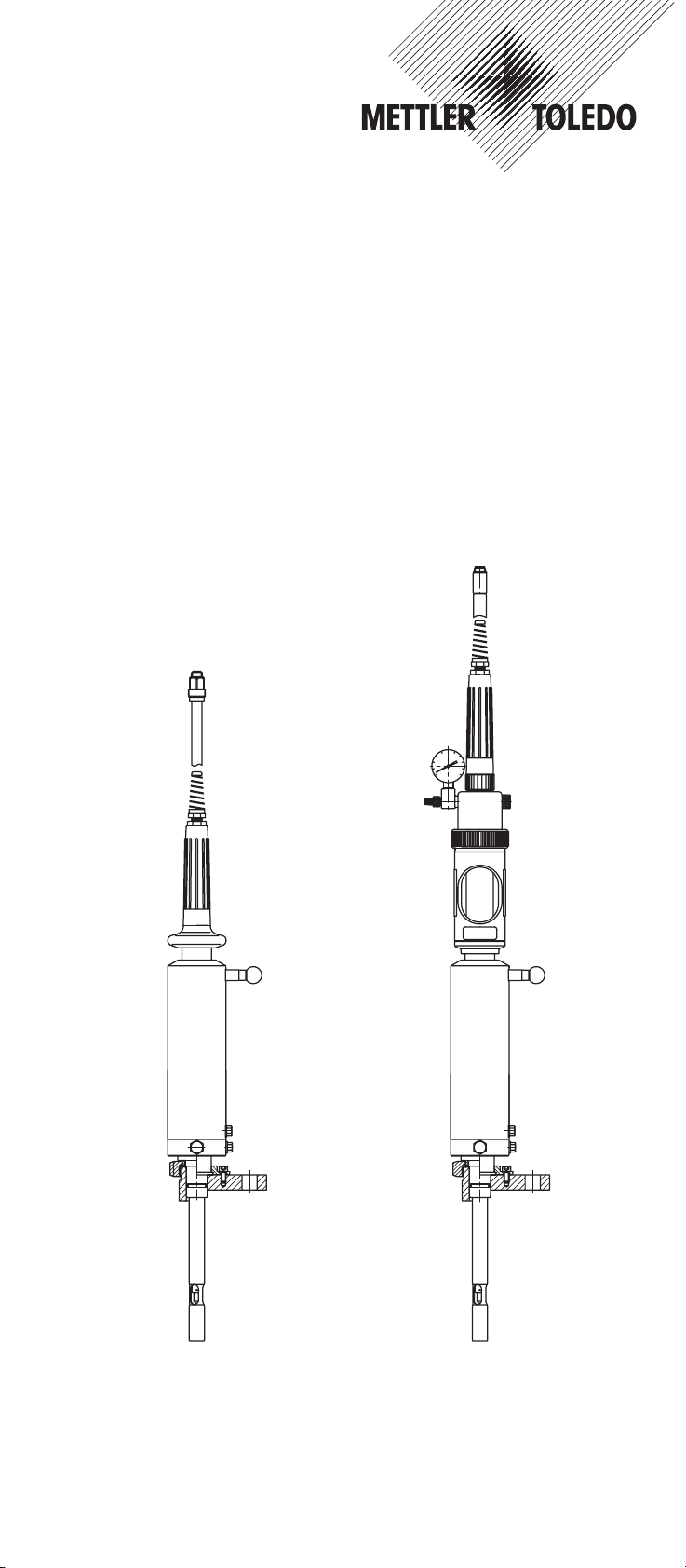
InTrac®777-SL
InTrac
®
776-SL
Instruction manual
Betriebsanleitung
Instructions d’utilisation
InTrac 777SL-04-CH
52 400 841

English Page 3
Deutsch Seite 41
Français Page 79
Herstellererklärung
(entsprechend der EG-Richtlinie 89/392/EWG)
Mettler-Toledo GmbH, Process Analytics, Im Hackacker 15, 8902 Urdorf, Schweiz
erklärt in alleiniger Verantwortung, dass die Produkte
InTrac
®
768, InTrac®769, InTrac®776-SL, InTrac®777-SL, InTrac®796, InTrac®797,
auf die sich diese Erklärung bezieht, den einschlägigen grundlegenden Sicherheits- und
Gesundheitsanforderungen der EG-Richtlinie 89/392/EWG entsprechen.
Achtung:
Wir weisen darauf hin, dass die Inbetriebnahme so lange untersagt ist, bis festgestellt
wurde, dass die Maschine, in welche diese Produkte eingebaut werden, den Bestimmungen der ihr zugrundeliegenden Richtlinien entspricht.
Manufacturer‘s Declaration
(according to EG Directive 89/392/EEC)
Mettler-Toledo GmbH, Process Analytics, Im Hackacker 15, 8902 Urdorf, Switzerland
herewith declares in sole responsibility that the products
InTrac
®
768, InTrac®769, InTrac®776-SL, InTrac®777-SL, InTrac®796, InTrac®797,
referred to in this declaration comply with the safety and health requirements of the EC
Directive 89/392/EEC.
Important:
We draw your attention to the fact that it is prohibited to put this products into service until
the machinery/equipment into which they will be to incorporated has been found and
declared to be in conformity with the provisions of those directives relevant to the machine/equipment in question.
Déclaration du fabricant
(selon directive 89/392/CEE)
Mettler-Toledo GmbH, Process Analytics, Im Hackacker 15, 8902 Urdorf, Suisse
déclare ci-après que les produits
InTrac
®
768, InTrac®769, InTrac®776-SL, InTrac®777-SL, InTrac®796, InTrac®797,
auxquels cette déclaration se réfère sont conformes aux dispositions de la directive
89/392/CEE.
Important:
Nous attirons votre attention sur le fait que la mise en service est interdite avant que la
machine dans laquelle les produits seront incorporés soit considérée et déclarée conforme
aux dispositions de la directive 89/392/CEE
Urdorf, 1. August 1998 O. Filliol
Leiter Geschäftsbereich Process

InTrac®777-SL / InTrac®776-SL 3
© 06/00 Mettler-Toledo GmbH, CH-8606 Greifensee InTrac 777-SL-04-CH
Printed in Switzerland 52 400 841
InTrac®777-SL
InTrac
®
776-SL
Instruction manual
To whom it may concern
Certificate of Quality
We Mettler-Toledo GmbH, Process Analytics
Im Hackacker 15
8902 Urdorf
Switzerland
hereby confirm that we have attained the Quality
Assurance Certificate ISO 9001 and the Environmental Certificate ISO 14001. The invoiced and
shipped goods are developed, produced and
tested according to the reguations of our Certified
Quality and Environmental Management Systems
and fulfil our technical specifications.
Description of goods Housing InTrac
®
776-SL../.. and
Housing InTrac
®
777-SL../..
Specification We confirm compliance with the specifications
issued by Mettler-Toledo GmbH Urdorf, per
August 1997 following TRB 801 No 45, issued
April 1996, «Special pressure vessels according to Appendix II of Paragraph 12 of regulations on Pressure Vessels: Housings of
Equipment Components»
Date Dezember, 21 1997

4 InTrac®777-SL / InTrac®776-SL
InTrac 777-SL-04-CH © 06/00 Mettler-Toledo GmbH, CH-8606 Greifensee
52 400 841 Printed in Switzerland
Contents
1. Introduction..........................................................................5
2. Important remarks ................................................................6
2.1 Checking the shipment ...........................................................6
2.2 Notes on operating instructions ...............................................6
2.3 Normal use...........................................................................7
2.4 Safety instructions..................................................................7
3. General product description ..................................................9
3.1 The different models...............................................................9
3.2 Construction of the retractable housings ...................................9
3.2.1 Operating modes of the retractable housings ...........................10
3.2.2 Lower part of housing for process adaption.............................10
3.3 Description of function..........................................................11
3.3.1 Manually operated housings .................................................11
3.3.2 Pneumatically operated housings ..........................................12
4. Installation/Startup and shutdown of manually ....................13
and pneumatically operated housings
4.1 Preparation of the equipment.................................................13
4.2 Fitting and installation work ..................................................15
4.2.1 Fitting the housing ...............................................................15
4.2.2 Attaching the flushing lines ...................................................16
4.2.3 Pneumatic connections ........................................................18
4.2.4 Installing the temperature sensor ...........................................19
4.2.5 Fitting the electrode/sensor ....................................................20
4.3 Startup procedure.................................................................22
4.3.1 Startup procedure for manually operated housings...................22
4.3.2 Startup procedure for pneumatically operated housings ............23
4.4 Shutdown procedure for manually and pneumatically ..............24
operated housings
4.5 Dismantling work.................................................................24
4.5.1 Removing the electrode/sensor ..............................................24
4.5.2 Removing the housing..........................................................25
4.6 Using of cable with BNC plugs ..............................................26
5. Operation ...........................................................................27
5.1 Important information for everyday operation...........................27
5.2 Inspection work in everyday operation....................................27
5.3 Cleaning the electrode/sensor................................................28
5.4 Calibrating the measurement system......................................28
6. Maintenance ......................................................................29
6.1 Important information on maintenance ...................................29
6.2 Topping up reference electrolyte.............................................29
6.3 Conversion of InTrac
®
SLM to InTrac®SLP/SLR .......................29
6.4 Conversion of InTrac
®
777-SL to InTrac®776-SL....................30
6.5 Replacing seals in contact with the process medium................30
7. Trouble-shooting.................................................................32
8. Product specifications.........................................................33
8.1 Standard equipment.............................................................33
8.2 Technical data.....................................................................34
8.3 Spare parts list ....................................................................35
8.3.1 Exploded drawing/Spare parts list InTrac
®
777-SL...................35
8.3.2 Exploded drawing/Spare parts list InTrac
®
776-SL...................37
9. Appendix............................................................................38
9.1 Suitable electrodes/sensors...................................................38

InTrac®777-SL / InTrac®776-SL 5
© 06/00 Mettler-Toledo GmbH, CH-8606 Greifensee InTrac 777-SL-04-CH
Printed in Switzerland 52 400 841
1. Introduction
These operating instructions contain all the information needed
for safe and proper use of the retractable housings InTrac
®
777-
SL and InTrac
®
776-SL.
The operating instructions are intended for personnel entrusted
with the operation and maintenance of the retractable housings.
It is assumed that these persons are familiar with the equipment
in which the retractable housing is installed.
Construction of the retractable housings employs leading-edge
technology and complies with safety regulations currently in
force (Mettler Toledo GmbH as the manufacturer has been
awarded ISO 9001/EN29001 certification). Notwithstanding
this, improper use could lead to hazards for the user or a thirdparty, and/or adverse effects on the plant or other equipment.
Therefore, the operating instructions must be read and under-
stood by the persons involved before work is started with the
retractable housing.
In addition to these operating instructions, you should also be
familiar with the following:
– All local safety regulations concerning the erection of pneu-
matic and water installations.
– All information and warnings in the documentation dealing
with the products used together with the retractable housing
(electrodes/sensors, control system, etc.).
– All safety regulations governing the equipment in which the
retractable housing is installed.
– All information and warnings affixed to the retractable hous-
ing.

6 InTrac®777-SL / InTrac®776-SL
2. Important remarks
Please read through this section carefully. It contains several
important points which will help you use the retractable housing
in a safe and proper manner.
2.1 Checking the shipment
On receipt of the shipment, check immediately:
– the retractable housing and accessories for transport dama-
ge. Report any damage immediately to the carrier and your
supplier.
– the type designation on the housing body.
– the shipment for completeness. Please notify your supplier
immediately if the shipment is incomplete (see Section 8.1
“Standard equipment”) or does not concur with the order and
delivery documents.
2.2 Notes on operating instructions
Restriction
The information contained in these operating instructions applies
only to the different models of the InTrac
®
777-SL and InTrac
®
776-SL retractable housings.
Detailed information on the electrodes/sensors and their installation is not given in these instructions. Such information can be
found in the separate documentation accompanying these products. Where necessary, appropriate cross-references to such
publications are given in these operating instructions.
Conventions
This pictogram represents safety and hazard warnings which,
if ignored, could result in injuries to personnel and/or material damage.
Storage
Please keep these operating instructions in a safe place where
they are always accessible.
If these instructions are lost, please contact your supplier for a
replacement.
Language versions
Operating instructions for the retractable housings InTrac
®
777-
SL and InTrac
®
776-SL are available in English, German and
French.
InTrac 777-SL-04-CH © 06/00 Mettler-Toledo GmbH, CH-8606 Greifensee
52 400 841 Printed in Switzerland
2.3 Normal use
The retractable housings are intended solely for measurement with the specified METTLER TOLEDO pH and redox
screwcap electrodes as well as 12 mm dissolved oxygen sensors, conductivity and turbidity sensors.
Use the retractable housings solely for this purpose. Usage which
differs from or exceeds this normal usage will be regarded as
usage not for the intended purpose.
The manufacturer/supplier accepts no responsibility for any
damage resulting from such improper usage. The risk is borne
entirely by the user.
Normal use also includes:
– Compliance with the instructions, regulations and informa-
tion in these operating instructions for the InTrac
®
777-SL
and InTrac
®
776-SL retractable housings.
– Adherence to the stipulated inspection and maintenance
intervals.
– Correct maintenance of the retractable housing.
– Operation with due observance of the stipulated environ-
mental and operating conditions (see Section 8.2) and the
admissible mounting positions.
2.4 Safety instructions
– The retractable housings InTrac®777-SL and InTrac®776-
SL should be installed, operated, maintained and, if need
be, repaired only by personnel familiar with the housing and
who are qualified for such work. The customer is responsi-
ble for ensuring that:
– only trained and authorized personnel work with the
retractable housings.
– the operating instructions should be supplemented by in-
house instructions regarding supervisory duties and obligation to report, work organization, personnel qualification, etc.
– Ensure that the material specification of your retractable
housing and of the seals satisfies the requirements of the
process and is compatible with the (vessel) cleaning solu-
tions used (see Section 8.2 “Technical data”). In case of
doubt, contact your supplier.
– Before every startup, the retractable housing must be
checked for:
– Damage to the connections, fastening, etc.
– Leaks
– Faulty cables
A defective retractable housing must neither be installed
nor put into service.
InTrac®777-SL / InTrac®776-SL 7
© 06/00 Mettler-Toledo GmbH, CH-8606 Greifensee InTrac 777-SL-04-CH
Printed in Switzerland 52 400 841

8 InTrac®777-SL / InTrac®776-SL
– If it is suspected that hazard-free operation is no longer pos-
sible (eg. housing damaged, connections and lines leaking), the retractable housing and the equipment in which the
retractable housing is installed must be shut down and secured against inadvertent operation.
– Before dismounting the retractable housing or commencing
any maintenance work on it, ensure that the equipment in
which the housing is installed is in a safe condition (depressurize, empty, rinse, purge, vent, etc.). Retractable housings
may only be stripped down after having been completely dismounted.
– Only the maintenance and repair work described in these
operating instructions may be performed on the retractable housings.
– When in the “Measuring” position, no maintenance or repair
work may be carried out on the retractable housing.
– When changing faulty components, use only original spare
parts obtainable from your supplier (see spare parts list, Section 8.3).
– No attachments or modifications to the retractable housings
and the accessories are allowed. The manufacturer/supplier
accepts no responsibility for damage caused by unauthorized attachments and modifications or the incorporation of
non-original spare parts. The risk is borne entirely by the
user.
– If the compressed air supply fails, the process pressure can
push the housing into the “Maintenance” position. The measuring signal will be falsified as the sensor no longer measures in the process medium. Therefore an automatic warning system for the compressed air supply should be installed.
Note: a power failure has no direct influence on the retractable housing, the measuring signal will however not be evaluated by the transmitter.
InTrac 777-SL-04-CH © 06/00 Mettler-Toledo GmbH, CH-8606 Greifensee
52 400 841 Printed in Switzerland
3. General product description
3.1 The different models
The retractable housings are available in different models, based
on:
– insertion lengths (“H”)
70 mm, 100 mm and 200 mm
– materials in contact with the medium (wetted parts)
stainless steel DIN 1.4435,
PVDF, PVC
– seal materials (O-rings) in contact with the medium
VITON
®
FDA and KALREZ
®
– adaption/connection alternatives
socket fastening (METTLER-TOLEDO ø25 mm),
flange fastening, external (male) thread
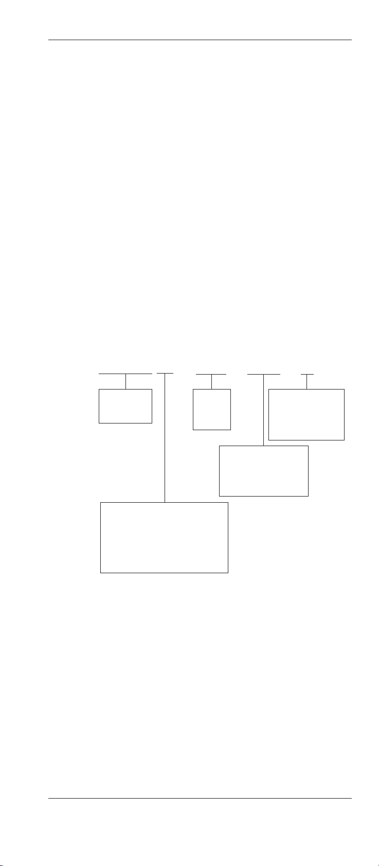
The type designation of the housing shows which model you
have.
For example:
InTrac777-SL-M70 / 1.4435 / D16-50 / Ka
InTrac®777-SL / InTrac®776-SL 9
© 06/00 Mettler-Toledo GmbH, CH-8606 Greifensee InTrac 777-SL-04-CH
Printed in Switzerland 52 400 841
Housing type:
InTrac777-SL
InTrac776-SL
Op. mode, immersion length in mm:
– M Manual
– P Pneumatic
– R Pneum.+position indic.
– 70 Immersion length 70 mm
– 100 Immersion length 100 mm
– 200 Immersion length 200 mm
Material:
1.4435
PVDF
PVC
Adaption/connection:
DN-25 weld-in sockets
D16-50 DIN flange
A150-2" ANSI flange
1" MNPT external thread
Seals/O-rings:
V Viton
Ka Kalrez
KF Kalrez FDA
S Special
3.2 Construction of the retractable housings
The InTrac®777-SL and InTrac®776-SL retractable housings
are differentiated by the types of electrode/sensor that can be
used:
– InTrac
®
777-SL without pressure compensation:
In this retractable housing, only pH/redox electrodes with
a polymer or gel-type electrolyte, 12 mm DO sensors, con-
ductivity or turbidity sensors can be used.
(eg. pH sensor HA405-DXK-S8, HA405-DPA-SC-S8)
– InTrac
®
776-SL with pressure compensation:
In this retractable housing only pH/redox electrodes/sensors with liquid electrolyte can be used.
(eg. pH sensor HA465-50-EQ-T-S7)
10 InTrac®777-SL / InTrac®776-SL
3.2.1 Operating modes of the retractable housings
Both versions of the InTrac®776-SL and InTrac®777-SL are
available with different modes of operation:
InTrac
®
776-SLM manual version
InTrac
®
777-SLM manual version
InTrac
®
776-SLP pneumatic version
InTrac
®
777-SLP pneumatic version
InTrac
®
776-SLR pneumatic with position indication
InTrac
®
777-SLR pneumatic with position indication
manual version pneumatic version pneumatic with
position indication
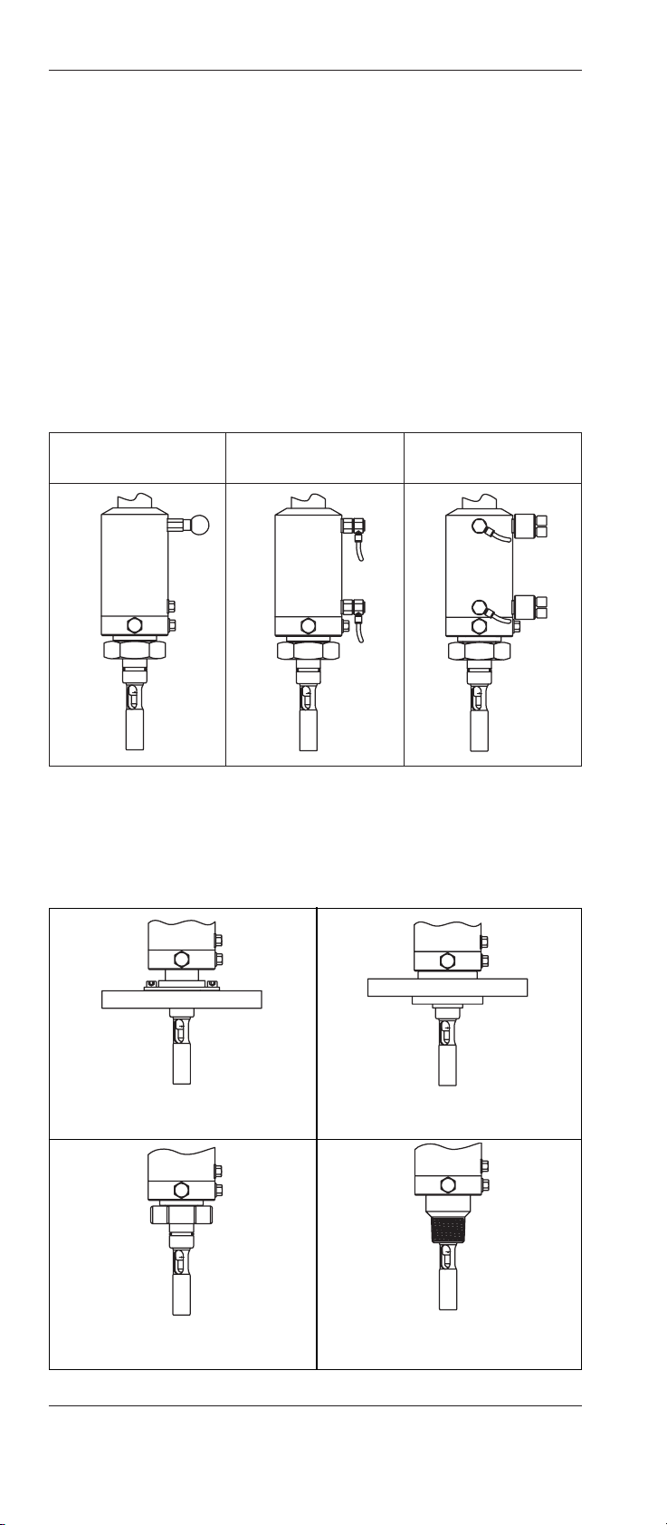
3.2.2 Lower part of housing for process adaption
Steel flange connection Polymer flange connection
Ring nut G1/4" External (male) thread 1" MNPT
MT weld-in socket DN25
InTrac 777-SL-04-CH © 06/00 Mettler-Toledo GmbH, CH-8606 Greifensee
52 400 841 Printed in Switzerland
3.3 Description of function
With the InTrac®777-SL and InTrac®776-SL retractable housings, electrodes/sensors can be cleaned or replaced without interrupting the ongoing process. Furthermore, it is possible to calibrate the measurement system with the electrode/sensor installed, using appropriate ancillary equipment.
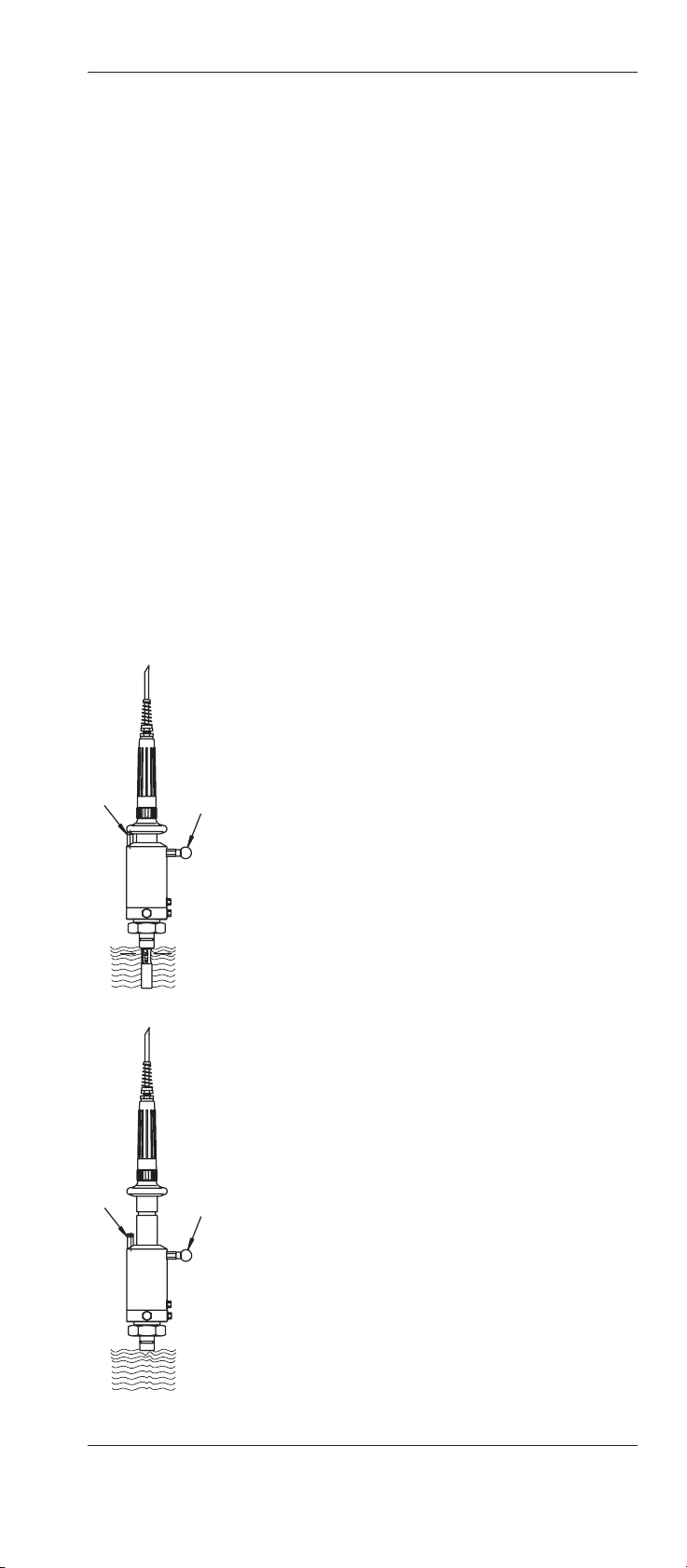
3.3.1 Manually operated housings
– InTrac®777-SLM
– InTrac
®
776-SLM
For manual versions, the immersion tube is moved into the desired end position (“Measuring” or “Maintenance”) by hand after
releasing the locking pin “B” by pulling out the red knob.
Important: The housings are equipped with an automatic sensor detection arrangement. If no electrode/sensor has been fitted in the housing, it is not possible to release the locking pin.
The housing remains in a locked position.
“Measuring” position, manual versions
In the “Measuring” position, the immersion tube is fully
inserted. The process medium flows past the tip of the
electrode/sensor through the openings at the end of the
immersion tube.
O-rings seal the housing against ingress of process
medium.
In the “Measuring” position the locking pin must latch
into the groove of the immersion tube. In addition, the
positioning pin “A” must engage the recess in the handle (protective sleeve). To do this, rotate the immersion
tube clockwise until pin “A” engages the groove.
“Maintenance” position, manual versions
In the “Maintenance” position, the electrode/sensor can
be cleaned or removed/exchanged, or the complete
measuring system calibrated with the electrode/sensor
installed. O-rings seal the housing against ingress of
process medium.
In the “Maintenance” postion the locking pin “B” must
snap into the hole in the piston. This is achieved by
turning the immersion tube clockwise.
InTrac®777-SL / InTrac®776-SL 11
© 06/00 Mettler-Toledo GmbH, CH-8606 Greifensee InTrac 777-SL-04-CH
Printed in Switzerland 52 400 841
A
B
A
B
12 InTrac®777-SL / InTrac®776-SL
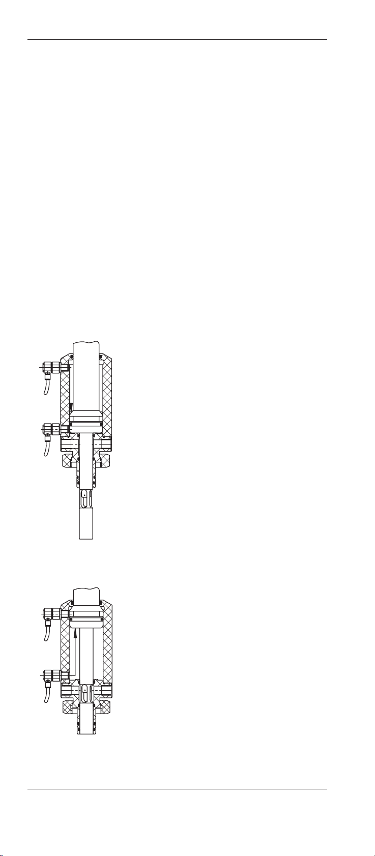
3.3.2 Pneumatically operated housings
– InTrac®777-SLP, InTrac®776-SLP
– InTrac
®
777-SLR, InTrac®776-SLR
(pneumatic versions with end position indicator)
The compressed air connections are used to pressurize the
piston of the immersion tube either from above or below. This
moves the immersion tube and hence the electrode/sensor either
downwards (to the “Measuring” position) or upwards (to the
“Maintenance” position). The piston remains pressurized with
compressed air at the respective end position.
In the versions equipped with a position indication system
(InTrac
®
777-SLR, InTrac®776-SLR), a signal is pneumatically triggered when the housing reaches the respective (“Measuring” or “Maintenance”) end position. This signal is transmitted
to a remote indicator (not included in housing supply).
“Measuring” position, pneumatic versions
In the “Measuring” position compressed air
pressurizes the immersion tube piston from
above. The process medium flows past the
electrode/sensor tip through the opening in the
immersion tube. O-rings seal the housing
against the sample medium.
“Maintenance” position, pneumatic versions
In the “Maintenance” position compressed air
pressurizes the immersion tube piston from
below. In this position the electrode/sensor can
be cleaned or removed/exchanged or the measurement system calibrated with the electrode/sensor installed. O-rings seal the housing
against the sample medium.
The housings are equipped with an automatic
sensor detection arrangement. If no electrode/sensor is fitted, or is improperly installed, the
housing will not move into the “Measuring”
position.
InTrac 777-SL-04-CH © 06/00 Mettler-Toledo GmbH, CH-8606 Greifensee
52 400 841 Printed in Switzerland
Warning! Installation of the retractable housings at other
than the admissible mounting positions is not allowed, since
in such positions proper functioning of the electrode/sensor
cannot be guaranteed.
4. Installation/Startup and shutdown of manually and pneumatically operated housings
4.1 Preparation of the equipment
The housings are mounted and fixed on the vessel (reactor, tank,
pipe, etc.) by means of a ring nut in conjunction with a weld-in
socket, by a flange connection or a 1" MNPT external (male)
thread.
Attachment of the weld-in socket or the flange connection to the
vessel is the responsibility of the customer.
Note: Weld-in sockets with thread G 11/4" (internal ø= 25 mm,
L= 40 mm, straight or at an angle of 15°) are available from
your supplier in a choice of materials.
Important! After welding, the bore of the weld-in socket must be
checked and reamed to size 25-H7 if necessary.
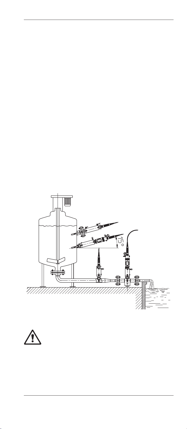
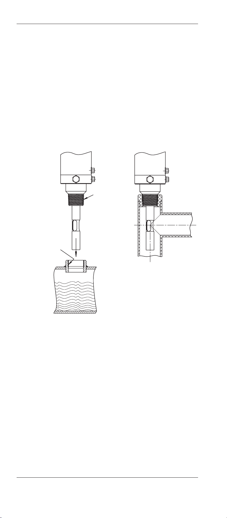
To ensure correct functioning of the retractable housing, please
note the following information on positioning:
– The retractable housing can be installed vertically or at an
angle. In the latter case, ensure that the angle of the housing is equal to or greater than 15° above the horizontal
(see following illustration).
InTrac®777-SL / InTrac®776-SL 13
© 06/00 Mettler-Toledo GmbH, CH-8606 Greifensee InTrac 777-SL-04-CH
Printed in Switzerland 52 400 841
Flange
Socket
Direct mounting
1" MNPT
Flow-through
14 InTrac®777-SL / InTrac®776-SL
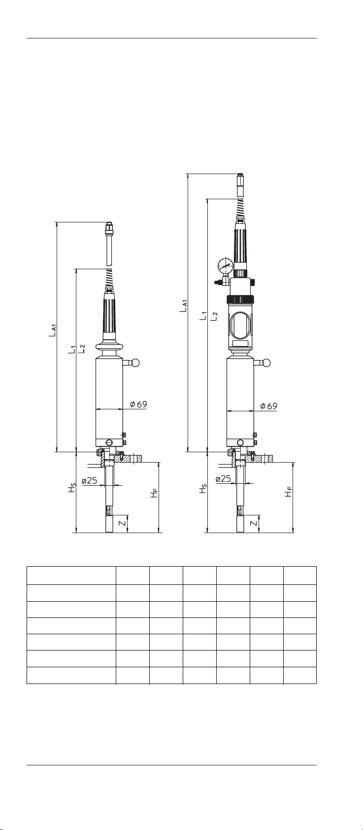
– The retractable housing should be mounted in a position
which allows sufficient clearance for its correct functioning
(correct measuring position in the medium) and maintenance (checks, installation and removal of the electrodes/
sensors). Depending on the type of housing, the following
dimensions must be taken into account:
All dimensions in mm
Type H
S
H
F
L
A1
L
1
L
2
Z
InTrac
®
777-SL/70 72 45 500 380 449 10(8)*
InTrac
®
777-SL/100 105 78 500 380 449 44
InTrac
®
777-SL/200 205 178 900 480 649 44
InTrac
®
776-SL/70 72 45 800 563 632 10(8)*
InTrac
®
776-SL/100 105 78 800 563 632 44
InTrac
®
776-SL/200 205 178 1200 663 832 44
* stainless steel versions
– Avoid mounting the retractable housing at exposed positi-
ons. If this is not possible, appropriate measures must be
taken to protect against damage.
InTrac 777-SL-04-CH © 06/00 Mettler-Toledo GmbH, CH-8606 Greifensee
52 400 841 Printed in Switzerland
InTrac® 777-SL InTrac® 776-SL
4.2 Fitting and installation work
Warning! In all installation work described below, ensure that
the equipment in which the housing is installed is in a non-hazardous condition (depressurized, empty, rinsed, purged, etc.)
4.2.1 Fitting the housing
Warning! Never place the housing on the front ends of the im-
mersion tube or the centering spigot (risk of damage). Ensure
that the housing is fitted to the correct, prescribed socket or flange
as directed.
Fitting of weld-in socket
1. Clean the centering spigot of the housing and the bore in the
weld-in socket (25-H7) checking for damage.
Warning! Fitting the retractable housing with a damaged
centering spigot or fitting the retractable housing in a damaged weld-in socket is not allowed and could lead to injuries
to personnel and/or damage to the housing or vessel.
2. Check the vessel to ensure that there are no obstacles in the
insertion direction which would prevent motion of the immersion tube.
3. Check the O-ring on the spigot for damage and replace it if
necessary. Lightly smear O-ring with grease. Ensure correct
quality and positioning of the O-ring.
4. Position the housing on the weld-in socket and carefully in-
sert spigot in the bore.
5. Finally, tighten ring nut firmly by hand.
Important! Use no tools (the seal between the housing and
the socket is made by the O-ring on the spigot).
Installation of flange
1. Clean the sealing surfaces of the flanges (housing and flan-
ge connection on vessel) and check for damage.
Warning! If process media are considered to be dangerous,
then it is imperative that an embedded seal is used at the
flange interface and/or a splash guard mounted. Fitting the
retractable housing with damaged flange connections is not
permissible and can lead to injuries to personnel and/or
damage to the housing or vessel.
2. Use the appropriate flange gasket and check for soundness.
N.B. Instruction valid for special materials only:
Ensure that TEFLON
®
seal is present on the flange of the
retractable housing and check for damage. Replace if necessary. Ensure correct quality and positioning of the TEFLON
®
seal.
InTrac®777-SL / InTrac®776-SL 15
© 06/00 Mettler-Toledo GmbH, CH-8606 Greifensee InTrac 777-SL-04-CH
Printed in Switzerland 52 400 841
16 InTrac®777-SL / InTrac®776-SL
InTrac 777-SL-04-CH © 06/00 Mettler-Toledo GmbH, CH-8606 Greifensee
52 400 841 Printed in Switzerland
3. Check the vessel to ensure there are no obstacles in the insertion direction which would prevent motion of the immersion tube.
4. Mount housing on the flange, align and tighten evenly crosswise with hex bolts and nuts.
Mounting with MNPT 1" external (male) thread
1. Wind Teflon
®
tape around the external (male) thread.
2. Screw the housing carefully into the counter-thread.
3. Check the installation for leaks.
1
2
4.2.2 Attaching the flushing lines
Important information
– When the electrode/sensor is withdrawn, small amounts of
the process medium adhere to the electrode/sensor tip and
can enter the outflow line during the rinsing process. If the
process medium is an environmentally harmful substance
(toxic, corrosive, etc.), it is essential to comply with the local
regulations governing the installation of wastewater services.
– Use only corrosion-resistant and chemically resistant mate-
rials for the rinsing water installation.
InTrac®777-SL / InTrac®776-SL 17
© 06/00 Mettler-Toledo GmbH, CH-8606 Greifensee InTrac 777-SL-04-CH
Printed in Switzerland 52 400 841
Effect of intermediate position of versions with
immersion depth H = 70 mm
When inserting and retracting the housing and if the mobile part
should become positioned between the proper IN and OUT end
positions, the process fluid may flow out through the lock chamber and flushing lines. This could create a hazard for personnel,
equipment and environment.
Recommendation for proper operation and safe use
All flushing lines must be equipped with valves which may only
be opened when the retractable part of the housing is in the maintenance position. After the flushing and maintenance of the sensors, the flushing valves must be closed.
Basic installation
The basic installation is intended for cleaning/flushing of the
electrodes/sensors when the housing is in the “Maintenance”
position.
– Inlet:
The inlet line is connected to rinsing water inlet “A” (thread
G 1/8") of the housing via an appropriate shut-off device
(dependent on the control unit used).
The permitted water pressure is 2 bar.
– Outlet:
For the water outlet, rinsing water outlet “B” (thread G 1/4")
is connected to a suitable drain (comply with local regulations).
Important! The water outlet should be positioned somewhat
higher than the inlet so that the lock chamber is always filled with water or buffer solution, and the pH electrode/ sensor cannot dry out even when the inlet is closed. If need be,
use a suitable lead-off (first upwards) to the outlet line to
ensure this.
AB
18 InTrac®777-SL / InTrac®776-SL
InTrac 777-SL-04-CH © 06/00 Mettler-Toledo GmbH, CH-8606 Greifensee
52 400 841 Printed in Switzerland
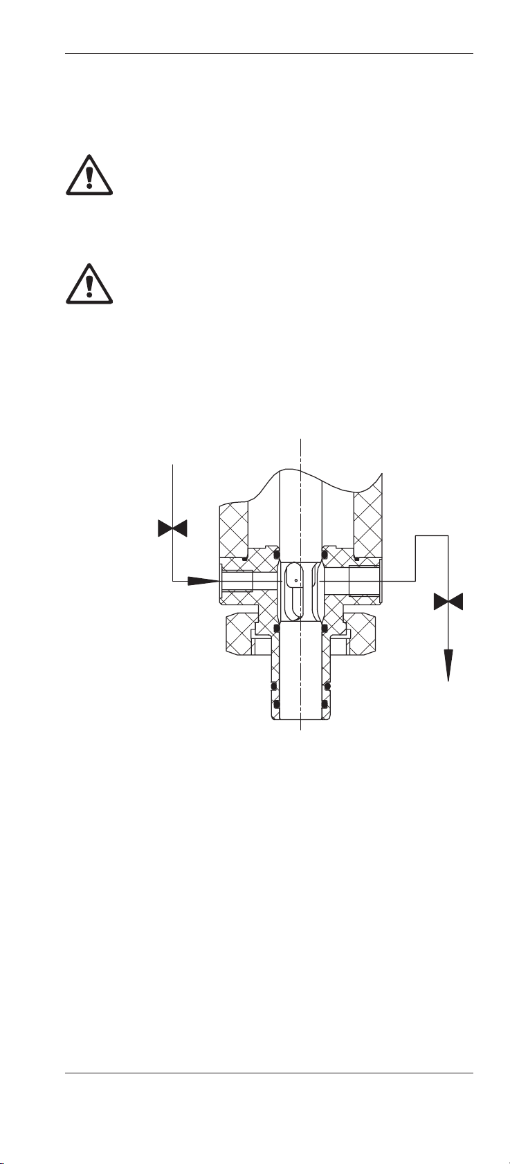
Installation for calibration of the measurement system with
electrode/sensor installed
If the measurement system (electrode/sensor and amplifier) has
to be calibrated with the electrode/sensor installed, a distributor
with 3 connections is attached to the connection (thread G 1/8”)
of the housing in place of the inlet line.
Make 3 connections as shown in the
adjacent schematic diagram:
• Connection “A” to the rinsing
water inlet via a shut-off valve.
• Connections “B” and “C” to the
corresponding buffer solution
supply, each via a non return
valve.
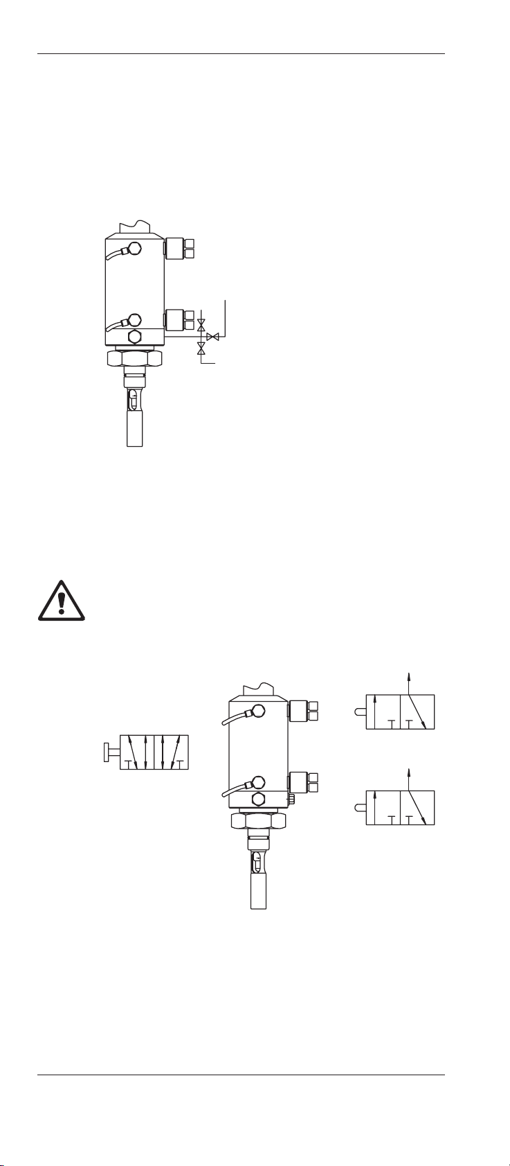
4.2.3 Pneumatic connections
For pneumatic operation of the housing, the housing connections “1” and “2” are to be linked to the air lines “1” and “2” as
below.
Attention! Only the original fittings supplied with the housing
may be used.
If the position indicator system is to be used, the two connections “3” and “4” are to be linked to the position indicator valves
“3” and “4”.
Legend
p = Compressed air supply
1 = Feed “Measurement”
2 = Feed “Maintenance”
P
3
= Feed Position indication “Maintenance”
P
4
= Feed Position indication “Measurement”
3 = Position indication “Maintenance”
4 = Position indication “Measurement”
A
B
C
1
2
3
4
12
P
3
4
P
3
P
4
InTrac®777-SL / InTrac®776-SL 19
© 06/00 Mettler-Toledo GmbH, CH-8606 Greifensee InTrac 777-SL-04-CH
Printed in Switzerland 52 400 841
Note:
– The permitted operating pressure of the pneumatic system is
8 bar.
– The pressure in the control air supply for the housing must
be at least 4 bar.
– The control air must be oil-free, and filtered.
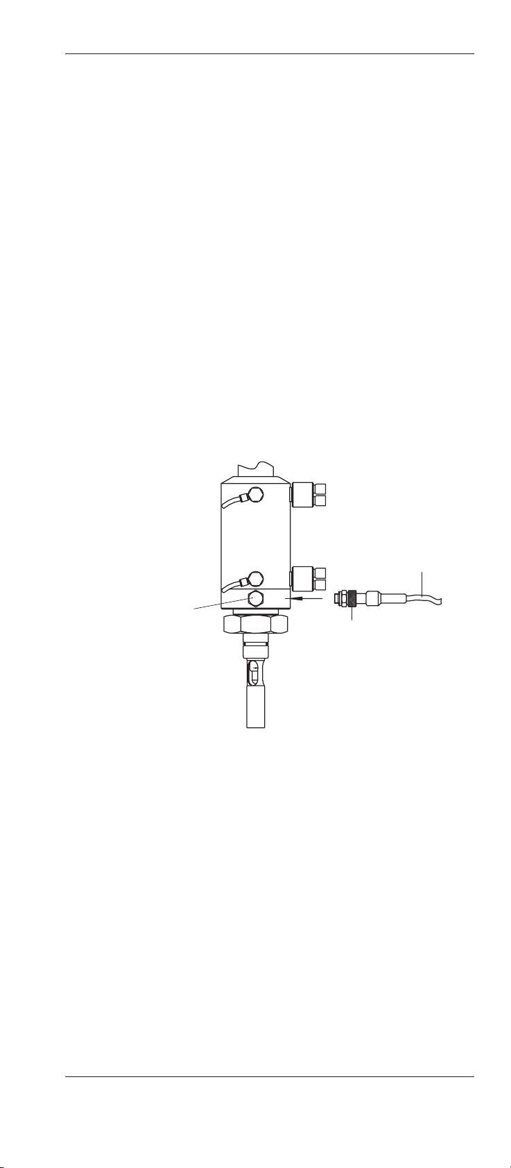
4.2.4 Installing the temperature sensor
During calibration of the measurement system, the temperature
of the calibration medium and therefore also of the electrode/
sensor (with exception of the turbidity sensor) must be taken into
account. To cover this aspect, a temperature sensor is connected to the amplifier.
For automatic temperature compensation during calibration of
the measurement system with an electrode/sensor installed, a
temperature sensor (eg. Pt100/Pt1000) should be installed
directly in the lock chamber.
For the Pt100/Pt1000 installation, proceed as follows:
1. Remove blind plug (thread G 1/8").
2. Screw in temperature sensor (Pt100/Pt1000) with sealing
ring then tighten using a small fork spanner.
3. Connect the temperature sensor to the corresponding input
of the amplifier input.
2
3
1
20 InTrac®777-SL / InTrac®776-SL
InTrac 777-SL-04-CH © 06/00 Mettler-Toledo GmbH, CH-8606 Greifensee
52 400 841 Printed in Switzerland
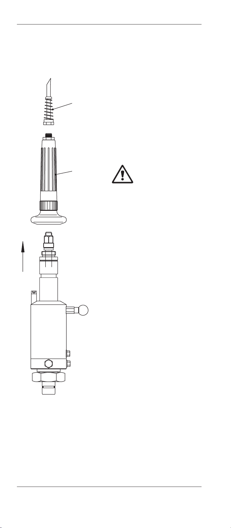
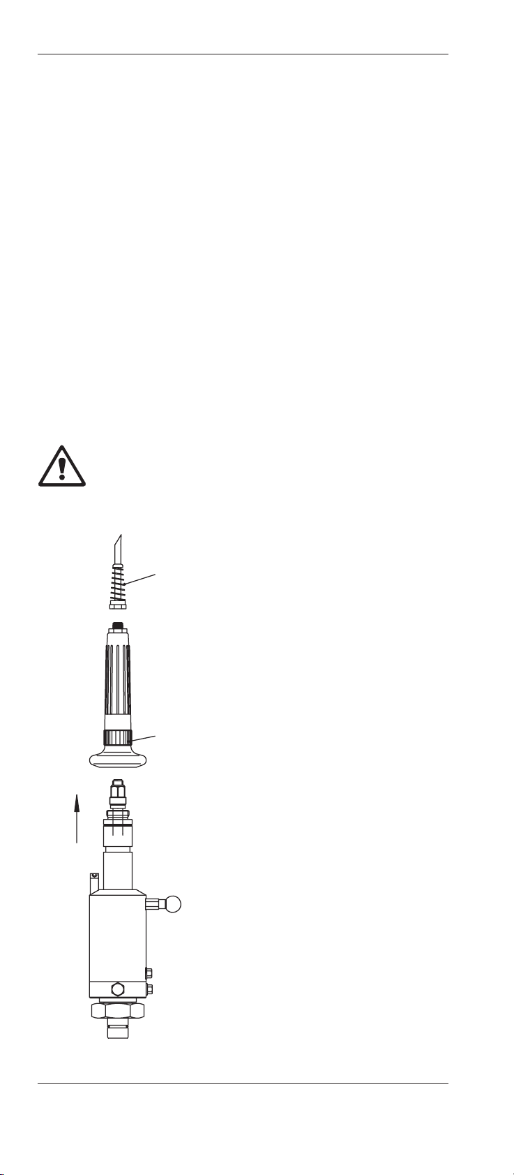
4.2.5 Fitting the electrode/sensor
InTrac®777-SL retractable housing
1. Set the housing to “Maintenance” position.
2. Remove the cable antikink “2”.
3. Unscrew the protective sleeve “3”.
4. Check that the correct electrode/sensor type has been selected (see Section 9 “Appendix”).
5. Check the electrode/sensor for damage (eg. electrode/sensor breakage).
Warning! A damaged electrode/sensor must never be
installed.
6. Check washers and O-rings on electrodes/sensors for damage and replace if necessary.
7. Remove watering cap from electrode/
sensor tip and rinse electrode/sensor
with water.
8. Carefully insert the electrode/sensor
into the immersion tube and screw in
by hand as far as it will go.
Important: use no tools!
9. Remove the screw cap cover on the
coaxial connection of the electrode/
sensor.
10.Run the connection cable through the
antikink “2” and the protective sleeve
“3”, and attach the plug to the electrode/sensor.
11.Mount protective sleeve “3” and tighten by hand. Finally, replace the cable
antikink “2”.
3
1
2
InTrac®777-SL / InTrac®776-SL 21
© 06/00 Mettler-Toledo GmbH, CH-8606 Greifensee InTrac 777-SL-04-CH
Printed in Switzerland 52 400 841
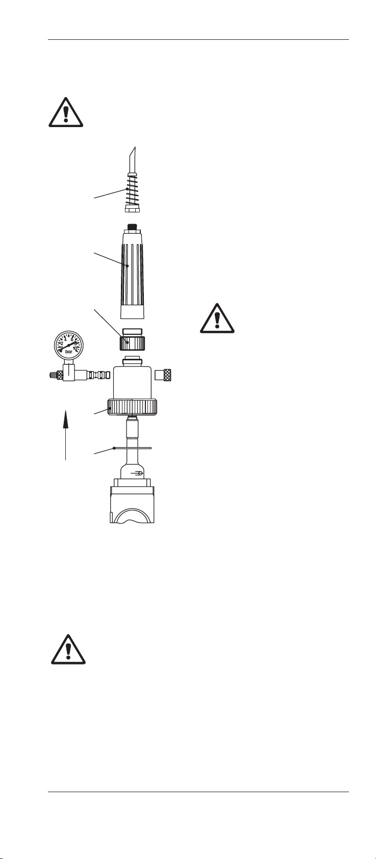
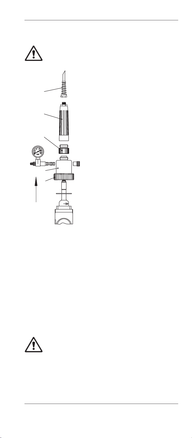
InTrac®776-SL retractable housing
Warning! If the ring nut “5“ and the plastic adapter “4” are tigh-
tened in the wrong order, the electrode may break. It is thus essential to follow the procedure described below.
1. Set the housing to “Maintenance” po-
sition.
2. Remove the cable antikink “2”.
3. Remove protective sleeve “3”, plastic
adapter “4” and ringnut “5”.
4. Check that the correct electrode type
has been selected (see Section 9 “Appendix”).
5. Check the electrode for damage (eg.
electrode breakage).
Warning! A damaged electrode must never be installed.
6. Remove watering cap from the electrode tip, the stopper from the filling
port, and the rubber band.
Rinse electrode with water.
Important! After removing the stopper, do not tilt the electrode as reference electrolyte may spill out.
7. Check the level of electrolyte and if necessary replenish (see instr. sheet of
the relative electrode).
8. Carefully insert electrode into the immersion tube until it comes up against
the TEFLON
®
cradle.
Important! If installing at an angle,
ensure that the marking “Position
electrode this side up” points upwards. In this position no reference
electrolyte can flow out of the filling
port (assuming fill level is correct).
9. Check flat gasket “6” of upper part of housing for damage
and replace if necessary. Mount upper part and tighten ring
nut “5” by hand.
Warning! Ring nut “5” of the upper part may be tightened
only with plastic adapter “4” removed.
10.Check seal of plastic adapter “4” and replace the complete
adapter if necessary. Mount plastic adapter “4” and tighten
by hand.
11.Remove the screw cap cover on the coaxial connection of
the electrode.
2
4
3
5
6
1
22 InTrac®777-SL / InTrac®776-SL
InTrac 777-SL-04-CH © 06/00 Mettler-Toledo GmbH, CH-8606 Greifensee
52 400 841 Printed in Switzerland
12.Run the connection cable through the antikink “2” and the
protective sleeve “3”, and attach the plug to the electrode.
13.Mount protective sleeve “3” and tighten by hand. Finally,
replace the cable antikink “2”.
14.Set the compensation pressure in the housing:
The compensation pressure can be set with a bicycle pump
via the valve core at the pressure gauge, or established by
attaching a permanent (oil-free) compressed air supply
(using the pressure connection set included in the standard
equipment).
Note: To ensure electrolyte flow from the reference electrode
to the sample medium, the air pressure in the upper part must
be at least 0.5 bar and max. 2 bar above that of the sam-
ple medium (take hydrostatic pressure of the sample medium into account).
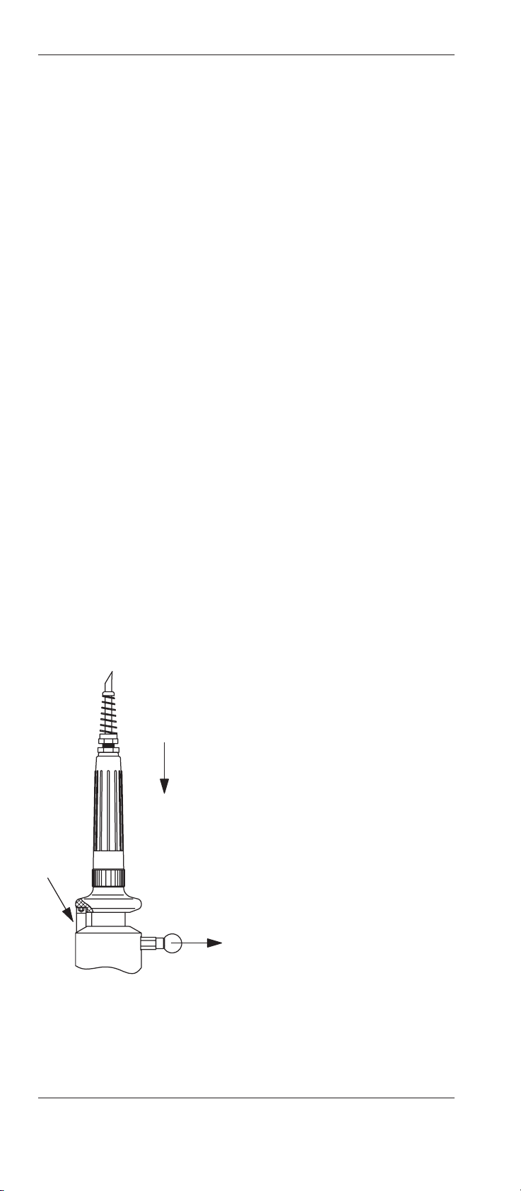
4.3 Startup procedure
4.3.1 Startup procedure for manually operated housings
Before startup, all fitting and installation work (see Section 4.2)
must have been completed! Each time before startup, check the
measuring system, inspect the electrode/sensor assembly and
examine for leaks from housing and apparatus (see also Section 7). Do not begin operation until the measuring system has
been checked and any necessary corrective action has been
taken.
Proceed as follows for startup:
1. Pull the red knob of the locking pin in
order to release the immersion tube.
2. Move immersion tube to the “Maintenance” position. The tube must engage the lower limit stop (for “InTrac
777-SLM”). When the handle (protective sleeve) reaches the positioning pin “A”, the immersion tube
should be turned clockwise until the
recess in the handle (protective sleeve) is in alignment with the positioning pin “A”. The immersion tube can
now be fully inserted into the “Measuring” position. There is an audible
click when the locking pin engages.
A
2
1

InTrac®777-SL / InTrac®776-SL 23
© 06/00 Mettler-Toledo GmbH, CH-8606 Greifensee InTrac 777-SL-04-CH
Printed in Switzerland 52 400 841
4.3.2 Startup procedure for pneumatically operated housings
Before startup, all fitting and installation work (see Section 4.2)
must have been completed! Each time before startup, check the
measuring system, inspect the electrode/sensor assembly and
examine for leaks from housing and apparatus (see also Section 7). Do not begin operation until the measuring system has
been checked and any necessary corrective action has been
taken.
Proceed as follows for startup:
1. Open air supply for the control air system. Check:
– insertion and withdrawal movement of the immersion
tube, as well as the status indication for the respective
end positions
– the control air system for tightness. Seal any leaking
connections immediately.
2. Move immersion tube to “Maintenance” position and open
rinsing water supply (2 bar). Check rinsing water system for
tightness. Seal leaking connections immediately.
3. If your system is equipped for calibration of the measurement
system, move the housing to the “Maintenance” position and
perform a calibration (see Section 5.4). In this case, check:
– the calibration procedure is correct.
– the buffer solution systems for tightness. Seal any lea-
king connections immediately.
On successful completion of all function checks, the equipment
in which the housing is installed can be started up.
Warning! Following startup of the equipment, particular care
must be exercised in operations at the retractable housing. Therefore it is essential to pay close attention to the information in
Section 5.1.
24 InTrac®777-SL / InTrac®776-SL
InTrac 777-SL-04-CH © 06/00 Mettler-Toledo GmbH, CH-8606 Greifensee
52 400 841 Printed in Switzerland
4.4 Shutdown procedure for manually and pneumatically operated housings
N.B. For InTrac“ 777-SL manually operated housings. locking
pin “B” must snap into the hole in the piston. This is achieved
by turning the immersion tube clockwise after withdrawal.
1. Move housing to the “Maintenance” position.
2. Open rinsing water supply, rinse electrode/sensor and close
rinsing water supply.
3. Ensure that the equipment in which the housing is installed
is in a non-hazardous condition (depressurize, empty, rinse,
purge, vent, etc.).
4. Close control air to pneumatic housings.
4.5 Dismantling work
4.5.1 Removing the electrode/sensor
Warning! Removal and installation of the electrodes/sensors
may be performed only in the “Maintenance” position.
InTrac
®
777-SL retractable housing
1. Set housing to the “Maintenance”
position, ensuring locking pin “B”
snaps into the hole in the piston (see
3.3.1)
2. Open rinsing water supply, rinse electrode/sensor and then close rinsing
water supply.
3. Remove cable antikink “3”.
4. Unscrew protective sleeve “4”.
5. Disconnect the signal cable from the
electrode.
6. Unscrew the electrode/sensor and carefully remove from immersion tube.
4
1
3
InTrac®777-SL / InTrac®776-SL 25
© 06/00 Mettler-Toledo GmbH, CH-8606 Greifensee InTrac 777-SL-04-CH
Printed in Switzerland 52 400 841
Retractable housing InTrac®776-SL
Warning! If the plastic adapter “4” and the ring nut “5” are undo-
ne in the wrong order, the pH/redox electrode may break. The-
refore it is essential to follow the procedure described below.
1. Move housing to the “Maintenance”
position.
2. Open rinsing water supply and rinse
electrode. Close rinsing water supply.
3. Depressurize the upper part by slightly loosening the valve core at the pressure gauge or by interrupting the compressed air supply. Then retight valve
core.
4. Remove cable antikink “2” and unscrew protective sleeve “3”.
5. Disconnect the signal cable from the
electrode.
6. Undo plastic adapter “4” and remove.
7. Undo ring nut “5” and remove upper
part “7”.
8. Carefully withdraw electrode from immersion tube.
Note: Specific information on the electrode (adjustment with the
measurement system, storage of the electrode, etc.) will be
found in the relative documentation for the electrode or measurement system.
4.5.2 Removing the housing
1. Shut down the housing (see Section 4.4).
2. Remove the electrode/sensor (see Section 4.5.1).
3. Dismantle rinsing water and control air lines.
Important! Close connections to prevent ingress of dirt.
4. Undo ring nut or flange connection and carefully remove
housing.
Warning! Never place the housing on the front ends of the
immersion tube or the centering spigot (risk of damage).
2
4
3
5
7
1
26 InTrac®777-SL / InTrac®776-SL
InTrac 777-SL-04-CH © 06/00 Mettler-Toledo GmbH, CH-8606 Greifensee
52 400 841 Printed in Switzerland
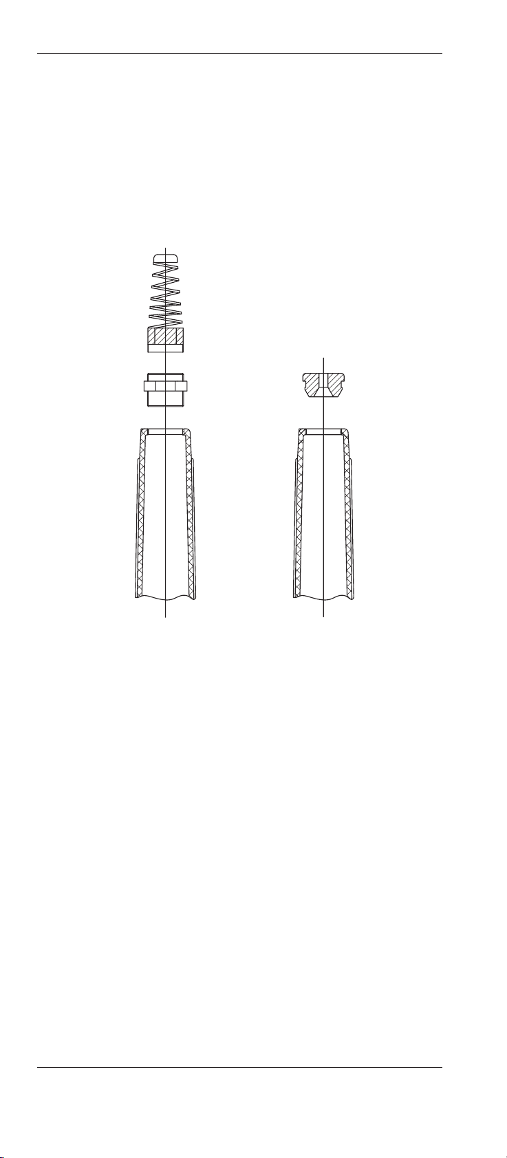
4.6 Using of cable with BNC plugs
If your pH cable has a BNC connector, you cannot use the standard rubber grommet with antiknick on the protective sleeve as
the bore is too narrow to allow passage of the BNC connector.
In this case, simply unscrew both the antiknick and the grommet (A), put the rubber split grommet around the cable instead,
and insert this into the protective sleeve (B).
AB

InTrac®777-SL / InTrac®776-SL 27
© 06/00 Mettler-Toledo GmbH, CH-8606 Greifensee InTrac 777-SL-04-CH
Printed in Switzerland 52 400 841
5. Operation
5.1 Important information for everyday operation
– Force must never be used to move the immersion tube into
the “Measuring” position without an electrode/sensor installed, otherwise process medium can flow out via the open
immersion tube!
– During operation, the following should never be loosened:
– the lines of the pneumatic system or of the rinsing and
buffer solutions.
– all fastening components (flange fastening, ring nut,
etc.).
– If any malfunctions occur during operation, the equipment in
which the housing is installed must first be made safe.
– For all work in everyday operation, wear the stipulated pro-
tective clothing (eg. protective goggles, gloves, breathing
apparatus, etc.).
5.2 Inspection work in everyday operation
The following inspection work should be performed in everyday
operation:
• Check all systems (air, rinsing water and, if used, buffer solutions) for leaks.
• Check fastening (ring nut, flange, NPT-thread) of the housing at the vessel for firm seating and leaks.
• Check the condition of the electrode/sensor. A faulty or damaged electrode/sensor must be replaced immediately.
Housings with pressure compensation (InTrac
®
776-SL):
• Check functioning of pressure gauge.
• Check air pressure in upper part (pressure gauge). The air
pressure must be at least 0.5 bar and maximum 2 bar above that of the sample medium (take hydrostatic pressure of
the sample medium into account) to ensure the electrolyte
flow from the reference electrode to the sample medium.
Note: The desired overpressure is set with a bicycle pump
via the valve core at the pressure gauge or established by
means of a compressed air supply.
• Check level of the reference electrolyte. The level of the reference electrolyte is steadily lowered owing to outflow through
the diaphragm. If the liquid level has sunk to below the bulb
mouth of the pH/redox electrode, the reference electrolyte
must be topped up (see Section 6 “Maintenance”).

28 InTrac®777-SL / InTrac®776-SL
InTrac 777-SL-04-CH © 06/00 Mettler-Toledo GmbH, CH-8606 Greifensee
52 400 841 Printed in Switzerland
5.3 Cleaning the electrode/sensor
The electrode/sensor must be cleaned before removal, before
calibration of the measurement system or at regular intervals
during operation (depending on the process medium). Proceed
as follows:
1. Set the housing to the “Maintenance”
position.
2. Open rinsing water supply and rinse
the electrode/sensors.
3. Close rinsing water supply.
5.4 Calibrating the measurement system
The frequency of calibration of the measurement system depends
on the electrode/sensor type and the sample medium.
To calibrate the measurement system, proceed as follows:
1. Set housing to the “Maintenance” position.
2. Open rinsing water supply, rinse electrode/sensor and then
close rinsing water supply.
3. Remove electrode/sensor (procedure, see Section 4.5.1).
Note: Step 3 above is only necessary if your installation does
not allow calibration of the measurement system with the
electrode/sensor installed.
4. Perform calibration in accordance with the operating instructions for the respective electrode/sensor and amplifier.
5. Re-install electrode/sensor (procedure, see Section 4.2.5).
Note: Step 5 above is only necessary if your installation does
not allow calibration of the measurement system with the
electrode/sensor installed.
6. Open rinsing water supply and rinse the electrode/sensor.
Close rinsing water supply.
7. Set the housing to the “Measuring” position.
InTrac®777-SL / InTrac®776-SL 29
© 06/00 Mettler-Toledo GmbH, CH-8606 Greifensee InTrac 777-SL-04-CH
Printed in Switzerland 52 400 841
6. Maintenance
6.1 Important information on maintenance
Attention! Maintenance and service work on the housings may
only be carried out by trained personnel.
Only the maintenance and repair work described in the following
chapters may be performed on the retractable housings.
Warning! It is possible that the process medium could harm the
environment and your health (toxic, corrosive, etc.). Hence,
ensure that the equipment is in a non-hazardous condition before you start with maintenance work.
6.2 Topping up reference electrolyte
The work described below applies only to pH/redox electrodes
with liquid reference electrolyte. To top up the reference electrolyte, proceed as follows:
1. Remove electrode (see Section 4.5.1).
Note: The reference electrolyte must not be topped up with
the electrode installed.
2. Top up reference electrolyte to the “Refill” mark on the electrode.
Important! Never exceed the maximum fill level.
3. Re-install electrode (see Section 4.2.5).
Do not allow spillage of reference electrolyte to remain in the
housing. Wash out and dry the housing.
6.3 Conversion of InTrac®SLM to InTrac®SLP/SLR
The manually operated version of the InTrac®SLM can be converted to a pneumatically operated version, but to avoid errors,
the conversion of the housing has to be done by the manufacturer.
Please contact your nearest dealer or Mettler-Toledo organisation.

30 InTrac®777-SL / InTrac®776-SL
InTrac 777-SL-04-CH © 06/00 Mettler-Toledo GmbH, CH-8606 Greifensee
52 400 841 Printed in Switzerland
6.4 Conversion of InTrac®777-SL to InTrac®776-SL
(for pH/redox electrodes only)
To carry out the conversion, proceed as follows:
1. Shut down the housing (see Section 4.4).
2. Remove the housing from its working location (see Section
4.5.2).
3. Unscrew the protective sleeve and disconnect the electrode
cable.
4. Remove the electrode.
5. Screw the adapter Order No. 52400857 for liquid-filled electrodes onto the top end of the immersion tube. Secure with
a set screw.
6. Insert an electrode of the liquid electrolyte type as in Section
4.2.5.
7. The housing is now ready for installation.
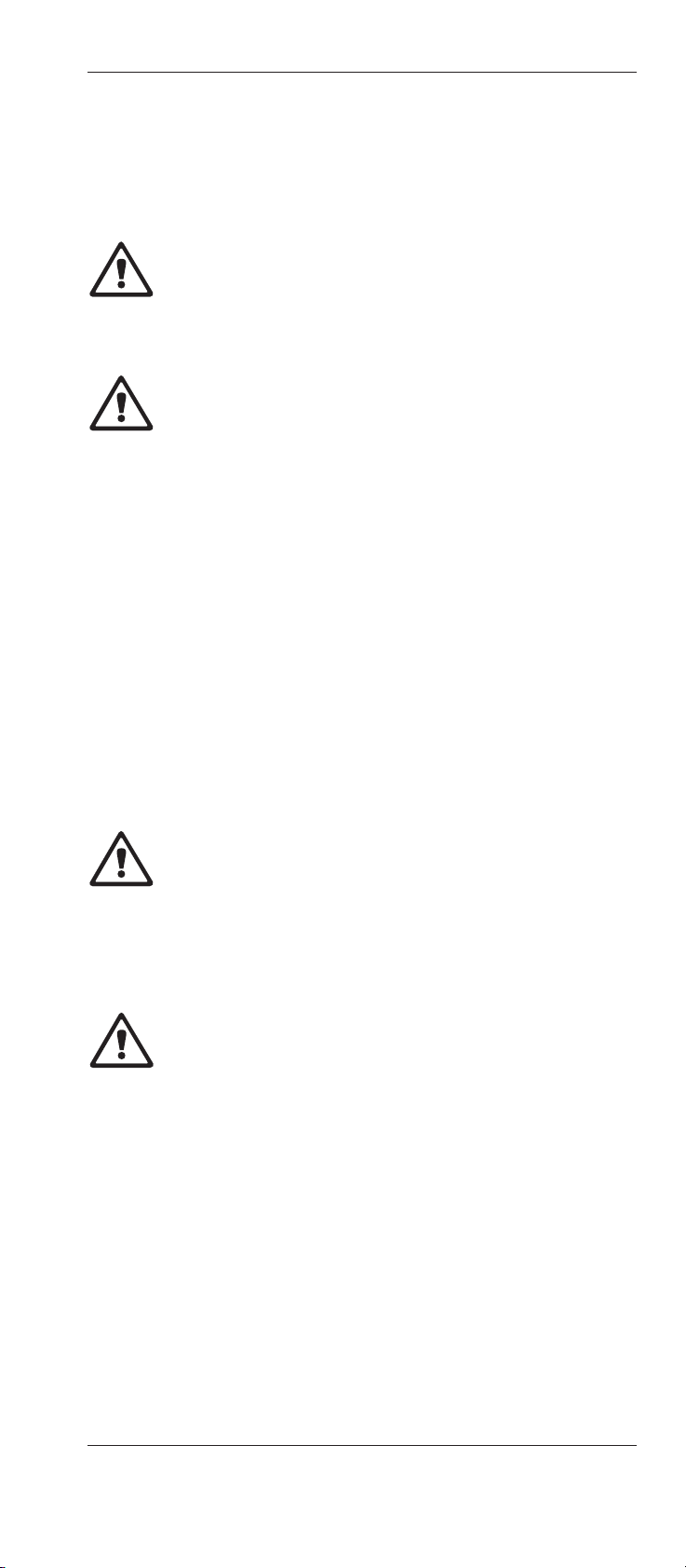
6.5 Replacing seals in contact with the process medium
All seals which come into contact with the process medium
should always be replaced at least once a year for reasons
of safety. With corrosive media, the seals may need to be chan-
ged at correspondingly shorter intervals.
1
2
2
3
2
 Loading...