

Mettler Toledo InSUS Instruction Manual

InSUS Head
30 283 375 C
InSUS Head for Optical
Single-Use O2Sensors
Instruction manual
Bedienungsanleitung
Instructions d’utilisation

2 InSUS Head
InSUS Head © 10/2018 Mettler-Toledo GmbH
30 283 375 C Printed in Switzerland
English Page 3
Deutsch Seite 23
Français Page 43

InSUS Head 3
© 10/2018 Mettler-Toledo GmbH InSUS Head
Printed in Switzerland 30 283 375 C
InSUS Head for Optical
Single-Use O2Sensors
Instruction manual

4 InSUS Head
InSUS Head © 10/2018 Mettler-Toledo GmbH
30 283 375 C Printed in Switzerland
1 Introduction.....................................................................5
2
Important notes ...............................................................6
2.1 Notes on operating instructions ..........................................6
2.2 Intended use ....................................................................6
2.3 Safety instructions.............................................................7
2.4 Examples of some typical applications................................7
3
Product description..........................................................8
3.1 General information ..........................................................8
3.2 Principle ..........................................................................8
3.3 Scope of delivery ..............................................................9
4 Installation....................................................................10
4.1 Connection ....................................................................10
4.1.1 Connection of the single-use sensor to the InSUS head........10
4.1.2 Digital connection of the InSUS head to a transmitter...........10
4.1.3 Analog connection of the InSUS head to a tranmitter or
controller .......................................................................11
4.1.4 Power connection of sensor head .....................................11
5 Operation......................................................................12
5.1 Configuration .................................................................12
5.1.1 Sensor head detection .....................................................12
5.1.2 Sampling rate.................................................................12
5.1.3 LED mode......................................................................12
5.2 Calibration .....................................................................13
5.2.1 Purpose of calibration .....................................................13
5.2.2 Factory calibration ..........................................................14
5.2.3 Single point calibration (Slope or Process Calibration) ........14
5.2.4 Process calibration ........................................................14
5.2.5 Dual point calibration with M400/M800 transmitter ...........15
5.2.6 Calibration when connected with analog signal
(via M50)......................................................................16
6 Maintenance .................................................................17
6.1 Sensor head inspection ...................................................17
6.1.1 Visual inspection ............................................................17
6.1.2 Testing the sensor with the transmitter...............................17
7 Storage.........................................................................18
8 Product specification .....................................................19
8.1 Specifications.................................................................19
9 Ordering information .....................................................20
9.1 Sensors .........................................................................20
9.2 Accessories....................................................................20
9.3 Recommended transmitters..............................................20
Contents

InSUS Head 5
© 10/2018 Mettler-Toledo GmbH InSUS Head
Printed in Switzerland 30 283 375 C
1
Introduction
Thank you for buying the optical oxygen sensor head
from METTLER TOLEDO.
T
he construction of INGOLD’s optical oxygen sensors
employs leading edge tech nology and complies with
s
afety regulations currently in force. Notwithstanding
this, improper use could lead to hazards for the user
or a third-party, and /or adverse effects on the plant or
other equipment.
Therefore, the operating instructions must be read
and understood by the persons involv ed before work
is started with the sensor.
The instruction manual must always be stored close at
hand, in a place accessible to all people working with
the sensor.
If you have questions, which are not or insufficiently
answered in this instruction manual, please contact
your METTLER TOLEDO supplier. They will be glad to
assist you.

6 InSUS Head
InSUS Head © 10/2018 Mettler-Toledo GmbH
30 283 375 C Printed in Switzerland
2 Important notes
2.1 Notes on operating instructions
These operating instructions contain all the information
n
eeded for safe and proper use of the optical sensor
head.
The operating instructions are intended for personnel
entrusted with the operation and maintenance of the
sensors. It is assumed that these persons are familiar
with the equipment in which the sensor is installed.
Warning notices and symbols
This instruction manual identifies safety instructions
and additional information by means of the following
symbols:
This symbol draws attention to safety instructions and
warnings of potential danger which, if neglected,
could result in injury to persons and/or damage to
property.
This symbol identifies additional information and
instructions which, if neglected, could lead to defects,
inefficient operation and possible loss of production.
2.2 Intended use
METTLER TOLEDO optical O2sensors are intended
solely for inline measurement of the oxygen partial
pressure, as described in this instruction manual.
Any use of these sensors which differs from or exceeds
the scope of use described in this instruction manual
will be regarded as inappropriate and incompatible
with the intended purpose. The manufacturer/supplier
accepts no responsibility whatsoever for any damage
resulting from such improper use. The risk is borne entirely by the user/ operator.
Other prerequisites for appropriate use include:
– compliance with the instructions, notes and
requirements set out in this instruction manual.
– acceptance of responsibility for regular inspection,
maintenance and functional testing of all asso ci ated components, also including compliance
with local operational and plant safety regulations.
– compliance with all information and warnings
given in the documentation relating to the products
used in conjunction with the sensor (single-use
bags, transmitters, etc.).
– observance of all safety regulations governing the
equipment in which the sensor is installed.
– correct equipment operation in conformance with
the prescribed environmental and operational
conditions, and admissible installation positions.
– consultation with Mettler-Toledo Process Analytics
in the event of any uncertainties.

InSUS Head 7
© 10/2018 Mettler-Toledo GmbH InSUS Head
Printed in Switzerland 30 283 375 C
2.3 Safety instructions
– The plant operator must be fully aware of the
potential risks and hazards attached to operation
of the particular process or plant. The operator is
responsible for correct training of the workforce, for
signs and markings indicating sources of possible
danger, and for the selection of appropriate,
state-of-the-art instrumentation.
– It is essential that personnel involved in the
commissioning, operation or maintenance of these
sensors or of any of the associated equipment (e.g.
single-use bags, transmitters, etc.) be properly
trained in the process itself, as well as in the use
and handling of the associated equipment. This
includes having read and understood this instruction manual.
– The safety of personnel as well as of the plant itself
is ultimately the responsibility of the plant operator.
This applies in particular in the case of plants
operating in hazardous zones.
– The oxygen sensors and associated components
have no effect on the process itself and cannot
influence it in the sense of any form of control
system.
– Maintenance and service intervals and schedules
depend on the application conditions, composition
of the sample media, plant equipment and signi ficance of the safety control features of the
measuring system. Processes vary considerably,
so that schedules, where such are specified, can
only be regarded as tentative and must in any case
be individually established and verified by the plant
operator.
– Where specific safeguards such as locks, labels,
or redundant measuring systems are necessary,
these must be provided by the plant operator.
– A defective sensor head must neither be installed
nor put into service.
– Only maintenance work described in this operating
instruction may be performed on the sensors.
– When changing faulty components, use only
original spare parts obtainable from your METTLER
TOLEDO supplier (see spare parts list, “Section 9”).
– No modifications to the sensors and the acces-
sories are allowed. The manufacturer accepts no
responsibility for damages caused by unauthorised
modifications. The risk is borne entirely by the user.
2.4 Examples of some typical applications
Below is a list of examples of typical fields of application for the oxygen sensors. This list is not exhaustive.
Measurement in liquids:
– Fermentation
– Bio-Tech

8 InSUS Head
InSUS Head © 10/2018 Mettler-Toledo GmbH
30 283 375 C Printed in Switzerland
3 Product description
3.1 General information
The optical single-use oxygen sensor, the InSUS fiber
optical cable (with integrated temperature probe), and
t
he InSUS head are used for measurement of oxygen in
single-use devices.
The single-use sensors are gamma irradiation steriliz-
able and are typically integrated in single-use devices
such as single-use bags and other similar applications. Please also refer to the documentation provided
by your single-use device supplier.
3.2 Principle
The optical oxygen sensors are based on an optical detection method, the so called fluorescence quenching.
Here is a short summary of the principle. In contrast to
the polarographic Clark-electrode, which detects a redox
reaction of oxygen at the electrode, the optical method is
based on an energy transfer between a chromophore
and oxygen.
– A chromophore, embedded in the sensor is illuminat-
ed with blue light. This chromophore absorbs the energy and if no oxygen is present emits red fluorescence light with a specific lifetime. This emitted light
is being detected by a detector in the sensor head.
– In the presence of oxygen, the chromophore transfers
the energy to the oxygen molecule. Oxygen is then
able to transfer this energy as heat to the surrounding
area and no fluorescence is emitted.
– The total intensity of the fluorescence and the lifetime
of the fluorescence is related to the Oxygen partial
pressure in the medium.
– To analyze the lifetime of the fluorescence, the exci-
tation light is pulsed with a constant frequency, the
emitted light shows the same course but with a time
delay to the excitation. This delay is called Phase
shift or Phase angle (Phi). The phase shift is dependent on the oxygen level and follows the Stern-Vollmer
correlation.
– The sensor head detects this phase shift and calcu-
lates the oxygen concentration.
– The oxygen value ist digitally transferred from the
InSUS Head to the transmitter.
InSUS Head 9
© 10/2018 Mettler-Toledo GmbH InSUS Head
Printed in Switzerland 30 283 375 C
3.3 Scope of delivery
Each sensor is supplied fully assembled and factory
tested and calibrated for correct function together with:
– a certificate of calibration
– this instruction manual
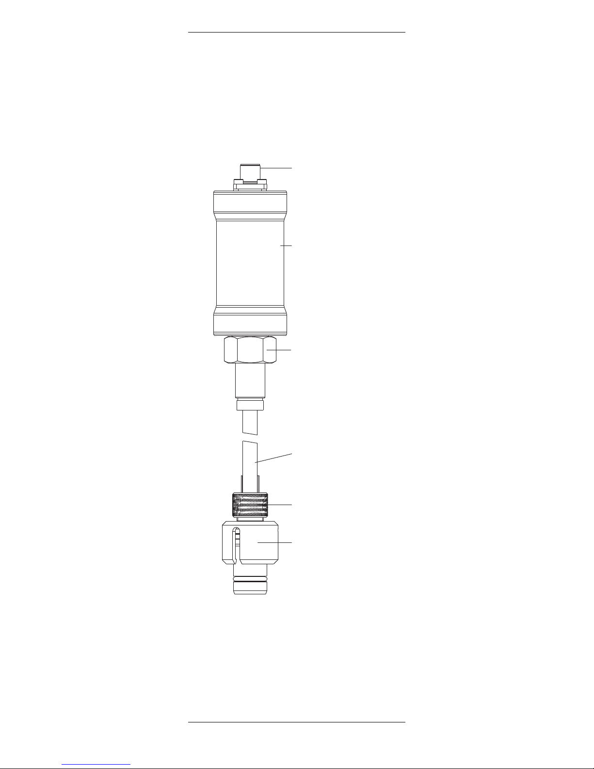
5 Pin
connector
InSUS head
InSUS head
connector
InSUS fiber
optical cable
Sensor connection
(M16 thread)
Single-use sensor
(integrated in
single-use device)

10 InSUS Head
InSUS Head © 10/2018 Mettler-Toledo GmbH
30 283 375 C Printed in Switzerland
4
Installation
4.1 Connection
4.1.1 Connection of the single-use sensor to the InSUS
head
Remove the protection cap from the single-use sensor.
Connect the single-use sensor and the InSUS head
with the corresponding InSUS fiber optical cable. Obs
erve the information sheet that accompanies the InSUS fiber optic cable, then tightly screw both plugs on
the sensor and the sensor head.
4.1.2 Digital connection of the InSUS head to a transmitter
Transmitter M400 or M800
The sensor head is connected to the transmitter via a
5 pin data cable. The cables are available from
METTLER TOLEDO in different lengths. The data cable
ensures a secure connection between the transmitter
and the sensor head under harsh industrial conditions.
To connect the data cable to the sensor head align the
slit of the connector with the pin in the plug, then tightly
screw the plug to fasten the two parts.
Transmitter M400
Note: For connecting the cable to the terminals of the
transmitter, please refer also to the instructions given
in the METTLER TOLEDO transmitter manual.
Connect the data cable to the tranmitter as described
in the tables below.
RS485 cable for InSUS Head
M400 M800 M800
1/2 channel 4 channel
Color Function TB4 TB2 TB2 or TB4
brown 24 VDC+ 19 9
black 24 VDC–2 10 10
gray shield 6 12 12
yellow shield 6 15 15
blue RS485–7 13 13
white RS485+ 8 14 14

InSUS Head 11
© 10/2018 Mettler-Toledo GmbH InSUS Head
Printed in Switzerland 30 283 375 C
4.1.3 Analog connection of the InSUS head to a transmitter or controller
A
METTLER TOLEDO M50 signal converter RS485 /
nano-Ampere mimics a polarographic Clark sensor.
The M50 signal converter is connected to an analog
signal input of a transmitter, e.g. M300, or biocont
roller. Please refer to the instructions given in the
METTLER TOLEDO M50 converter manual.
4.1.4 Power connection of sensor head
If the sensor is used with a 4-wire transmitter (M400 /
M800/M50), the Sensor Head is powered over the
transmitter.
Power Supply Specification: 24 VDC; 500 mA

12 InSUS Head
InSUS Head © 10/2018 Mettler-Toledo GmbH
30 283 375 C Printed in Switzerland
5
Operation
5.1 Configuration
5.1.1 Sensor head detection
B
efore installing an optical sensor, please refer to the
manual for the transmitter and configure the transmitter
for automatic sensor detection. Date and time must be
set correctly in the transmitter.
In the case wrong date and time are set, the calibration
and setup might be corrupted
5.1.2 Sampling rate
Optical oxygen sensors do not measure permanently.
Each measurement cycle has a duration of approx.
1 second. The measurement interval can be set to any
value between 1 and 60 seconds. Please choose the
appropriate setting. Default setting is 3 seconds which
is sufficient for most applications.
5.1.3 LED mode
The measurement can be switched off if the system is
not needed.
When the sensor head is not measuring, the sensor
LED is off. In this state the sensor head sends a constant measurement value of –1% air to the transmitter
and the transmitter is set to the “Hold mode”. To configure the “Hold mode” please refer to the transmitter
manual.
Automatic switch off at high temperature
If the LED mode is set to “Auto” (default setting) the sensor LED will be switched off as soon as a specific
process temperature is reached.
Temperatures
Maximum operating Default switch
temperature off temperature
InSUS Head 60°C/140°F 60°C/140°F
This limit can be set to an individual value by the user.
Using the transmitter (M400 ot M800) or with iSense.
These settings are also active if the sensor is operated
with an M50 signal converter. The switch off temperature
should be set at least 5° higher then the highest process
temperature. For example, if the process temperature is
37°C/ 99°F, 42°C/ 104°F should be the minimum setpoint. In this situation, as soon as the temperature exceeds 42°C/ 104°F the sensor will stop measuring and
the LED will be switched off. For the switch on, a hysteresis of 3° is implemented, meaning that the sensor
(and LED) will be switched on as soon as the temperature drops below 39°C/101°F.
Manual switch off of the sensor head
(M400/M800 transmitter)
The sensor can be switched off manually via the transmitter menu (see the transmitter manual) by setting
the LED mode to “off”. To restart the measurement, the
LED mode needs to be set manually to “on” via the

InSUS Head 13
© 10/2018 Mettler-Toledo GmbH InSUS Head
Printed in Switzerland 30 283 375 C
transmitter menu, or via a remote signal (digital input).
Remote switch off of the sensor head
(
M400/M800 transmitter)
The M400 transmitter can be set to “Hold” by applying
an external digital signal (see the transmitter manual).
In this situation the sensor and the sensor LED are
s
witched off. As soon as the “Hold Mode” is off, the optical sensor will continue to measure using the previous
settings.
5.2 Calibration
5.2.1 Purpose of calibration
Information about the calibration, you find also in the
manual of the transmitter.
Calibration must be performed every time a new single-use sensor is connected to the InSUS head via the
InSUS optical fiber cable.
Since the correlation between the measured phase and
the oxygen value is not linear, a calibration of an optical sensor must be performed very accurately. Wrong
calibrations may significantly reduce the measurement
accuracy.
Each oxygen sensor has its own individual phase
angle at zero oxygen (phi 0) and hundred percent air
saturation (phi 100).
Several methods for calibration are available for the
optical oxygen sensors. The highest measurement accuracy is achieved by performing a 2-point calibration
with air and a zero gas e.g. N
2
or CO2with a purity of
at least 99.9%.
Note: Please take into account the correct air pressure and humidity. Small deviations in air (± 3%)
are due to differences in humidity and process pressure settings. The sensor calculates for 100 % humidity if it is set to dissolved oxygen measurement.
General remarks:
– Calibration must be performed after gamma ster-
ilization of the single-use device.
– For calibration in gas the single-use device in
which the single-use sensor is integrated must be
filled with air (phi 100) or zero point gas (phi
0).
– Make sure that the settings for oxygen saturation
of the calibration is correct and remains constant
during calibration.
– In the event of calibration in water or sample medium,
the calibration medium must be in equilibrium
with the air. Oxygen exchange between water and
air is very slow. Therefore it takes quite long time until
water is saturated with atmospheric oxygen.
– Make sure that all other parameters, such as
temperature and pressure, are constant.
– Calibration always needs accurate pressure and
temperature measurement. Only process scaling is

14 InSUS Head
InSUS Head © 10/2018 Mettler-Toledo GmbH
30 283 375 C Printed in Switzerland
independent of those parameters (see chapter
5.2.4).
– Make sure that the correct calibration pressure, hu-
midity and salinity values are set in the transmitter
b
efore the calibration is started.
–
Please refer also to the transmitter or biocontroller
manual for detailed informations
5.2.2 Factory calibration
The sensor head is delivered pre calibrated and ready
for use.
The factory calibration data are stored in the sensor
and can not be changed by the user.
5.2.3 Single point calibration (Slope or Process Calibration)
For most applications, a single point calibration should
be sufficient.
By carrying out a single point calibration, the factual
phase at the desired oxygen value e.g. at hundred percent oxygen (phi 100) of the sensor can be established. The corresponding calibration curve is calculated.
The calibration medium can be either air or a calibration gas with known O
2
concentration or water with a
known oxygen concentration.
Before starting the calibration in gas, the correct pres-
sure and the correct humidity have to be set in the
transmitter.
Note: Wrong pressure values are the most common
reasons for bad measurement accuracy.
E.g. 50 mbar difference between the ambient pressure
and the value set in the transmitter result in 5% measurement error at air.
For calibration in gas it is important that the temperature reading of the sensor is stable and represents the
real gas temperature.
After the sensor signal has stabilized, the complete
meas uring system can then be calibrated to the 100 %
value of the desired measurable variable, e.g. 100%
air, 20.95% O2, or 8.26 ppm at 25°C (77°F) and
normal pressure (see instruction manual for the
transmitter).
5.2.4 Process calibration
For detailed information please refer also to the trans mitter manual.
Two different routines for process calibration are possible:
– Process calibration
– Process scaling (M400/ M800 transmitter)

InSUS Head 15
© 10/2018 Mettler-Toledo GmbH InSUS Head
Printed in Switzerland 30 283 375 C
Process calibration is performed when a reliable control value is available and process pressure is known.
Process pressure is only needed if the system is meas
uring in saturation (% air or % O
2
)
or gas (ppm gas)
units. During this calibration the phase values of the
calibration curve are adjusted.
Process scaling is performed mainly in biopharma
applications when the user desires to set the system to
an initial value. During this calibration the phase valu
es of the sensor are not adjusted, only the displayed
values and the 4 – 20 mA output are rescaled to the desired value.
Note: For process calibration the operator can use either the process pressure or the calibration pressure,
depending on how the reference value is taken.
After the sensor signal has stabilized, the complete
measurement system can be calibrated to the desired
variable, e.g. % air, % O
2
, ppm or ppb (see instruction
manual for the transmitter).
Note: For this type of calibration an accurate reference value and correct pressure settings are essential.
5.2.5 Dual point calibration with M400 / M800 transmitter
To receive a maximum accuracy of the measured values over the full measuring range, a dual point calibration is required.
By carrying out a dual point calibration both phase
angles at zero oxygen (phi 0) and at hundred percent
oxygen (phi 100) of the sensor can be established.
Point 1: Slope correction (with air or other calibration
media with known O2value)
After the sensor signal has stabilized, the complete
meas uring system can then be calibrated to the 100 %
value of the desired measurable variable, e.g. 100%
air, 20.95% O2, or 8.26 ppm at 25°C (77°F) and
normal pressure (see instruction manual for the
transmitter).
Point 2: Zero point
After the sensor signal has stabilized, the sensor can
be calibrated to the 0% value of the desired measurable variable, e.g. 0% air, 0.0% O
2
, or 0 ppm at
25˚C/77 ˚F (see instruction manual for the transmitter).
Note: Incorrect zero point calibration is a frequent
source of measurement error. For correct calibration, we recommend the use of nitrogen gas or other
oxygen-free medium with a level of purity of at least
99.9%.

16 InSUS Head
InSUS Head © 10/2018 Mettler-Toledo GmbH
30 283 375 C Printed in Switzerland
5.2.6 Calibration when connected with analog signal
(via M50)
As soon as a sensor is connected with an analog communication, only rescaling of the M50 output is available.
The procedures can be performed the same way as
with amperometric sensors:
1. Slope correction
2
. Offset correction

InSUS Head 17
© 10/2018 Mettler-Toledo GmbH InSUS Head
Printed in Switzerland 30 283 375 C
6
Maintenance
Note: All maintenance work can be done without any
tools.
6.1 Sensor head inspection
6.1.1 Visual inspection
T
o check your sensor head, we recommend the follow-
ing procedure:
– The contacts of the connector must be dry. Moisture,
corrosion and dirt in the connector can lead to false
readings.
– Check the cable for buckling, brittle areas or ruptures.
– Check the contacts of the InSUS fiber optical cable.
Attention! Do not use any cleaning agents contai ning alcohol or any solvents. This could damage the
sensor head.
6.1.2 Testing the sensor with the transmitter
If the measured values differ from the expected value,
a air calibration should be performed.
Appropriate phase values after a correct calibration:
Depending on the age of the single-use sensor the
phase values typically decrease over time compared
with a new single-use sensor (see table).
New sensor Limit for old sensor
Phi0 Phi100 Phi0 Phi100
62°±3° 35°±3° <58° >38°
The phase values of the sensor are stored in the cali-
bration history. The actual phase value can be checked
in the “Calibration – Verify” menu.
If after such procedures the above mentioned values
are still not reached, the sensor should not be used.
Zero oxygen measurement can be done by using
CO2or nitrogen (N2), alternatively in a sample medium
saturated with one of these gases.
After 2 minutes in an oxygen-free sample medium, the
reading on the transmitter should drop to below 5% of
the reading in ambient air, and within 10 minutes the
value should have dropped to below 1%.
If after such procedures the above mentioned values
are still not reached, the sensor should not be used.

18 InSUS Head
InSUS Head © 10/2018 Mettler-Toledo GmbH
30 283 375 C Printed in Switzerland
7 Storage
For storage, the sensor head should be clean and dry.
T
he protection caps have to be placed on the sensor
and the cable connectors.

InSUS Head 19
© 10/2018 Mettler-Toledo GmbH InSUS Head
Printed in Switzerland 30 283 375 C
8
Product specification
8.1 Specifications
InSUS Head
Measurement principle optical
Power requirements
U
min
= 19.5 VDC
U
max
= ≤25 VDC
P
m
ax
= 0.75 W ➝ 33 … 40 mA
Design features
Temperature compensation automatic with built-in RTD in InSUS
fiber optical cable
Cable connection (digital) data cable 5 pin
Single-use O
2
sensor integrated in
single-use device
Sensing element Optical spot
Measuring range 0…250% air
Accuracy under defined laboratory < 2.5% for the range 50– 100%
conditions air after 1-point calibration in
100% air
<1% after two point calibration in
100% air and 0% oxygen
Response time T98<30s
Temperature probe Pt1000 class B according to DIN
EN60751, integrated in InSUS opti-
cal fiber cable
Recommended wetting time 10 minutes
(preconditioning time)
Operating temperature 5°C to 60°C (41 °F to 140°F)
Sensor cable connection Glass fiber extension, M16 ×1
thread

20 InSUS Head
InSUS Head © 10/2018 Mettler-Toledo GmbH
30 283 375 C Printed in Switzerland
9
Ordering information
For more detailed information ask your local distributor.
9.1 Sensors
InSUS Head 30 015 171
InSUS fiber optical cable (1.5m/4.9 ft) 30 020 711
9.2 Accessories
M50 Signal converter 52 121 854
iSense 30 130 614
iSense CFR21 ready 30 283 620
iLink RS485 52 300 399
Data cable (5 pin)
Temperature range – 30 … 80 °C (– 22 … 176 °F)
2m (6.6ft) 52 300 379
5m (16.4ft) 52 300 380
10m (32.8ft) 52 300 381
15m (49.2ft) 52 206 422
25m (82.0ft) 52 206 529
50m (164ft) 52 206 530
9.3 Recommended transmitters
Transmitter
M400, Type 2 52 121 349
M400, Type 3 52 121 350
M800 1-channel 30 026 633
M800 2-channel 52 121 813
M800 4-channel 52 121 853
 Loading...