

Mettler Toledo InPro 8200/S, InPro 8000, InPro 8050, InPro 8200/H, InPro 8100/S Instruction Manual

InPro®8000 Series
52 800 247
InPro®8000 Series
Turbidity sensors
Trübungssensoren
Sondes de turbidité
Instruction manual
Bedienungsanleitung
Instructions d'utilisation

English page 3
German page 21
French page 39

InPro®8000 Series 3
© 01/04 Mettler-Toledo GmbH, CH-8606 Greifensee InPro®8000 Series
Printed in Switzerland 52 800 247
InPro®8000 Series
Turbidity sensors
Instruction manual
Subject to technical changes without prior notice.
© It is strictly forbidden to reprint this instruction manual or any parts
thereof without the written permission of Mettler-Toledo GmbH, Process
Analytics, Industrie Nord, 8902 Urdorf, Switzerland. No section or excerpt
whatsoever may be reproduced or with the assistance of electronic systems be edited, duplicated or distributed, in particular in the form of
photocopies, photographs, magnetic media or other recording methods.
All rights reserved, especially the right of duplication and translation as
well as in regard to patent and registration rights.
Mettler-Toledo GmbH, 8606 Greifensee, Switzerland

4 InPro®8000 Series
InPro®8000 Series © 01/04 Mettler-Toledo GmbH, CH-8606 Greifensee
52 800 247 Printed in Switzerland
Contents
1 Product description 5
1.1 Introduction 5
1.2 Equipment and scope of delivery 6
1.3 Technical data 6/7/8
2 Safety 9
2.1 Application compatibility 9
2.2 Proper utilization 9
2.3 Safety measures 9
2.4 Ex-Declaration 10
2.4.1 Use in Ex-zones 10
2.4.2 Ex-Classification 11
3 Initial start-up 12
3.1 Handling 12
3.2 Installation in vessels/reactors 12
3.3 Installation in pipes 13
3.4 Calibration in open laboratory vessels 13
3.5 Fiber optic cable extensions 13
4 Maintenance and troubleshooting 14
4.1 Conditions of warranty 14
4.2 Maintenance 14
5 Removal from operation, storage, disposal 15
5.1 Removal from operation 15
5.2 Storage 15
5.3 Disposal 15
6 Dimensional drawings 16
7 Ordering information 17
7.1 Sensors 17
7.2 Accessories 17/18
8 Certificates 19
8.1 Material certificate 19

InPro®8000 Series 5
© 01/04 Mettler-Toledo GmbH, CH-8606 Greifensee InPro®8000 Series
Printed in Switzerland 52 800 247
1. Product description
1.1 Introduction
We thank you for your decision to purchase a METTLER TOLEDO
InPro®8000 Series fiber optic measuring sensor with operation based on
the principle of backward scattered light.
Please keep this instruction manual in a safe place where it is readily to
hand for users of this sensor. If you have any questions regarding function
of the sensor and ancillary equipment, or if you consider that the descriptions/instructions do not tally or are lacking, please contact your nearest
METTLER TOLEDO Authorized Distributor, who will be pleased to provide
assistance.
Markings
The markings labeled on each sensor state the following information:
METTLER TOLEDO
Serial no. xxxxxx Order no. 52 xxx xxx
The code following the model designation of the InPro®8100 and
InPro®8200 Sensors as printed on the package label provides information
on the shaft material, sealing material for the optical window (if present),
and the length of the shaft in mm.
e.g. InPro®8200/S/Kalrez®-FDA/205
with S = stainless steel shaft DIN1.4435 or 1.4404 (316L)
Kalrez®-FDA 6230 window seal
shaft length = 205 mm (8.07").
In addition:
H = Hastelloy C276 shaft
Epoxy = Epoxy bonded window
See also chapter 7.1: Ordering information sensors.

6 InPro®8000 Series
InPro®8000 Series © 01/04 Mettler-Toledo GmbH, CH-8606 Greifensee
52 800 247 Printed in Switzerland
1.2 Equipment and scope of delivery
Scope of delivery
The sensors of the InPro®8000 Series are delivered ready for use including
fiber optic cable. Each sensor is accompanied by this instruction manual.
A METTLER TOLEDO Process System for the measurement of turbidity or of
suspended particles is completed by a METTLER TOLEDO Turbidity Transmitter Type Trb8300 (order no. 52 800 204). Detailed information for
calibration of the measuring system can be found in the following relevant
transmitter instruction manuals:
German Order no. 52 800 243
English Order no. 52 800 244
French Order no. 52 800 245
Packaging
The packaging consists of cardboard and foamed plastic. Safekeep the
packaging for later use during storage or transportation of the sensor. Should
you wish to dispose of the packaging material, please observe your local
regulations as well as those data and instructions given in chapter 5.3 of
this manual.
Unpacking and inspection
Please check the sensors immediately during unpacking in order to
determine possible damage or missing items. Any irregularities should
immediately be notified to your carrier and to your supplier.
1.3 Technical data
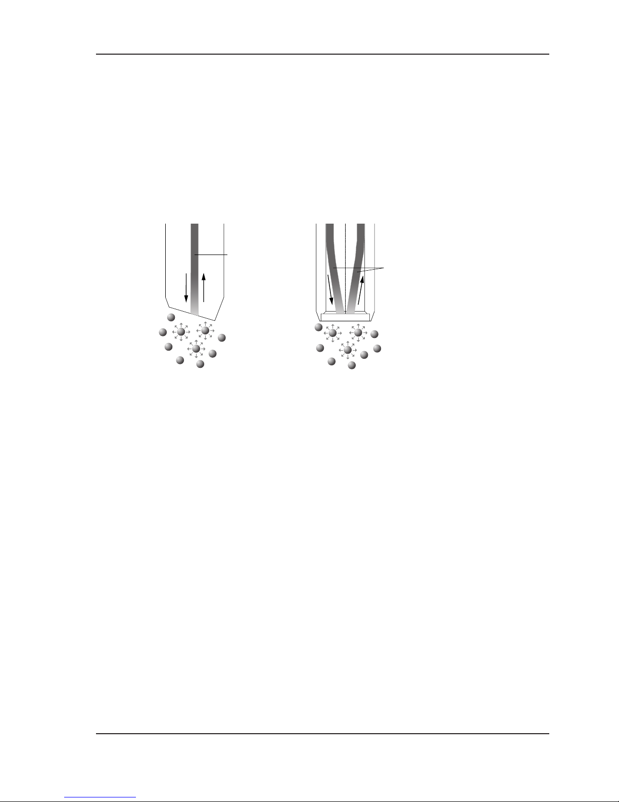
Function
Sensors of the InPro®8000 Series are optical sensors which measure the
concentration of suspended particles in a liquid medium on the basis of the
principle of backscattered light. The Transmitter Trb8300 is equipped with
a LED which beams a light – almost in the infra-red range (wavelength 880
nm) – via a fiber optic cable into the liquid medium. If the light hits on particles, then it is scattered in all directions. The light scattered at an angle of
InPro®8000 Series 7
© 01/04 Mettler-Toledo GmbH, CH-8606 Greifensee InPro®8000 Series
Printed in Switzerland 52 800 247
180° (backscattered light) is captured and led back via a fiber optic cable
to a photodiode in the transmitter, processed as photocurrent and the
signal transformed into a value for the transmitter display.
The sensors are divided into two types, single and dual optical fiber
sensors. The difference relates to the number of optical fibers present at the
end (nose) of the sensor shaft.
At low particle concentrations, the measuring range is expressed in FTU
(Formazin Turbidity Units). At high concentrations, the measurements are
given in grams of suspended solids per liter of sample volume, using
diatomaceous earth as reference substance.
optical fiber
optical fibers

8 InPro®8000 Series
InPro®8000 Series © 01/04 Mettler-Toledo GmbH, CH-8606 Greifensee
52 800 247 Printed in Switzerland
Technical data
Technical data InPro®8200/S(H) InPro®8100/S InPro®8050
Meas. principle dual fiber single fiber single fiber
Shaft material DIN1.4435 or 1.4404 1.4435 or 1.4404 PSU (Polysulfone)
(316L) (316L)
or Hastelloy C276
(available only with
Epoxy sealed window)
Shaft diameter 12 mm 12 mm 12 mm
Shaft length 120, 205, 120, 205, 120 mm
297 or 407 mm 297 or 407 mm
Window material Sapphire without window Sapphire spigot
O-ring sealing Viton®-FDA Viton®-FDA Viton®-FDA
Process adaption Pg13.5 Pg 13.5 Pg13.5
Plug 2 x SMA 2 x SMA 2 x SMA
Measuring range 5 FTU…4000 FTU 10 FTU…4000 FTU 10 FTU…4000 FTU
0…30 g/l 0…250 g/l 0…250 g/l
Pressure range 0…6 bar (0…87 psi) 0…6 bar (0…87 psi) 0…2 bar (0...29 psi)
with Kalrez®-FDA sealed
window
0...16 bar (0...232 psi)
with Epoxy bonded window
Temperature range –10…130 °C –30…130 °C 0…60 °C
(14…266 °F) (–22…266 °F) (32…140 °F)
with Kalrez®-FDA sealed
window
–30…130 °C
(–22…266 °F) with
Epoxy bonded window
Steam-sterilizable 130 °C (only with 130 °C non-sterilizable
Kalrez®-FDA sealed
window)
Subject to technical changes.
All sensors fall into the category described in Article 3, Paragraph 3 of the Pressure
Equipment Directive, 97/23/EC.

InPro®8000 Series 9
© 01/04 Mettler-Toledo GmbH, CH-8606 Greifensee InPro®8000 Series
Printed in Switzerland 52 800 247
2. Safety
2.1 Application compatibility
The wetted material parts of the sensor (shaft, window, window sealing material, O-ring) can under circumstance be non-compatible with the particular composition of the process medium and/or of the operating conditions. Responsibility to verify application compatibility lies wholly with the
user.
The compatibility of different types of material are outlined on http://www.
coleparmer.com/techinfo/chemcomp.asp
. Mettler-Toledo GmbH, Process
Analytics accepts no responsibility whatsoever for the correctness or accuracy of such details.
2.2 Proper utilization
METTLER TOLEDO InPro®8000 Series sensors are intended solely for the
measurement of suspended particles or turbidity in aqueous solutions in
industrial applications.
Any other use, or any operation over and above that intended by the
manufacturer, are deemed to be non-permissible and incorrect, and can
lead to harm or injury to material/equipment and persons. This is also
relevant for applications which do not comply with the technical data of the
sensor. For any damage possibly arising from such misuse, the user
assumes full and sole responsibility.
2.3 Safety measures
The sensors InPro®8000 Series have been manufactured in line with
state-of-the-art technology and in accordance with accepted technical
safety regulations. Nevertheless, the sensors can still represent a source of
risk and danger:
– if the sensors are operated by insufficiently trained personnel,
– if the sensors are employed incorrectly or not as intended by
the manufacturer
– if the sensors are not regularly maintained or serviced.
10 InPro®8000 Series
InPro®8000 Series © 01/04 Mettler-Toledo GmbH, CH-8606 Greifensee
52 800 247 Printed in Switzerland
Local legislation and regulations must be observed at all times. Such
stipulations do not form an integral part of this instruction manual.
It is on principle necessary for persons handling or using the sensors
to wear personal safety outfit such as protective goggles and protective
clothing.
The user is responsible for the instruction and training of personnel. In this
respect, additional copies of the instruction manual can be ordered from
your supplier. This instruction manual is an essential element of the sensor equipment and must at all times be readily to hand for operators
directly at the location of employment of the sensors.
Before the sensor is removed from the process/process adapter, it must be
ensured that the process pressure has been reduced to a safe level and the
process temperature lowered to a safe range. Any escape of hot process
medium under pressure can cause damage to material/equipment or injury to persons.
No modification whatsoever may be carried out on the sensors. Any
unauthorized modification or manipulation of the sensors results in immediate expiry of the full scope of warranty granted by the manufacturer.
2.4 Ex-Declaration
2.4.1 Use in Ex-zones
Note: Before installation in Ex-zones, please read and observe the follo-
wing guidelines:
Ex-Classification:
II 1/2G T6/T5/T4
Designation and number of the test certificate:
SNCH 03 ATEX 3565 X

InPro®8000 Series 11
© 01/04 Mettler-Toledo GmbH, CH-8606 Greifensee InPro®8000 Series
Printed in Switzerland 52 800 247
2.4.2 Ex-Classification II 1/2G T6/T5/T4 according to
EU type test certificate SNCH 03 ATEX 3565 X
Introduction
The turbidity sensors METTLER TOLEDO InPro 81XX/82XX */*/*/* may be
used in accordance with EN 60079-14:1997 in the categories 1 to 3 (Zones 0 to 2) and gas groups IIA, IIB und IIC subject to explosion risk through
combustible materials in the range of temperature classes T4 to T6.
Radiation flux < 5,19 mW
Pulse energy < 0,519 µJ
Mean radiation flux < 0,13 mW
Mean intensity of irradiation
at end of fiber-optic light guide < 0,458 mW/mm2
Irradiation H am
at end of fiber-optic light guide <
1,835 µJ/mm2
Turbidity sensor operated in conjunction with transmitter Trb 8300.
Special conditions
The maximum permissible ambient temperature for each individual temperature class is as shown in the following table:
Temperature class Max. ambient temperature
T 6 80 °C
T 5 95 °C
T 4 130 °C
– The turbidity sensors METTLER TOLEDO InPro 81XX/82XX */*/*/* may
only be used in the suitable METTLER TOLEDO housings InFit Typ 76**** or InTrac Typ 7**-*** in areas subject to explosion risk.
– The measuring system drawings must be followed for installation.
– The metal body of the turbidity sensors as well as the safety weld-in
sockets and housings METTLER TOLEDO InFit Typ 76*-*** and InTrac
Typ 7**-*** must be electrically connected to the potential equalizing
system of the installation.

12 InPro®8000 Series
InPro®8000 Series © 01/04 Mettler-Toledo GmbH, CH-8606 Greifensee
52 800 247 Printed in Switzerland
– The metal body of the turbidity sensors as well as the safety weld-in
sockets METTLER TOLEDO housing InFit Typ 76*-*** and InTrac 7**-***
are, if necessary, to be included into the recurring pressure test of the unit.
– The turbidity sensors may only be operated in conjunction with the
transmitter Trb 8300.
3. Initial start-up
3.1 Handling
The fiber optic cables have a core of Hard Clad Silica (HCS) fibers. When
laying fiber optic cables, the bend radius must always exceed at least
10 cm (4"). Fiberoptic cables may never be shortened independently.
Fitting of the SMA plug requires special tooling. The transparent plastic cap
on the sensor is to be removed before use. Any formation of deposits of
solid particles on the surface is to be avoided. Gas bubbles in the process
medium are also able to produce a signal and are therefore to be avoided
wherever possible. If this is not viable, please refer to the instruction
manual of the METTLER TOLEDO Transmitters Trb8300 (chapter:
«Calibration»).
3.2 Installation in vessels/reactors
The turbidity sensors are to be installed at a distance of at least 10 cm (4")
from the walls of the vessel, agitator and other internals, in order to prevent
disturbances through reflections. When employing special METTLER
TOLEDO retractable housings InTrac with modified immersion tubes, the
installation guideline valid for each individual housing is to be observed.
This step likewise, is to avoid measurement disturbances arising from
irrelevant light reflections (see chapter 7.2: «Accessories/Housings»).

InPro®8000 Series 13
© 01/04 Mettler-Toledo GmbH, CH-8606 Greifensee InPro®8000 Series
Printed in Switzerland 52 800 247
3.3 Installation in pipes
The turbidity sensors are to be installed such that the distance from the pipe
walls is at least 10 cm (4"). If this is not feasible in pipes of small diameter, then the sensor can be installed sloped, at an angle of 15…45° or, alternatively, in a knee bend. The pipe must always be completely full of liquid.
3.4 Calibration in open laboratory vessels
If the turbidity measuring system is calibrated off-line, it is recommended
to use the METTLER TOLEDO calibration tool, «CaliCap» (order no. 52 800
210), for fitting on the sensor shaft. If «CaliCap» is not used, a minimum
distance of 10 cm (4") to the vessel walls has to be observed as well.
During calibration, the sample should be stirred in order to prevent the
sedimentation of solid particles.
3.5 Fiber optic cable extensions
Fiber optic cables are available according to the list in chapter 7.2
«Accessories». The duplex cable extensions are supplied complete with
four fitted SMA plugs and two couplings. The two SMA plugs of the sensor
fixed cable are to be screwed hand-tight onto the couplings. Two SMA plugs
of the extension cable can then also be screwed by hand onto the couplings
in any order. To protect the cable connection from dust and splashwater, it
is recommended to use the METTLER TOLEDO Connection Box IP65
(Nema 4X) (order no. 52 800 241).
If extension cables are installed subsequently at a later date, the
measuring system has to be newly calibrated (see instruction manual for
the METTLER TOLEDO Transmitters Trb8300, chapter: «Calibration»).

14 InPro®8000 Series
InPro®8000 Series © 01/04 Mettler-Toledo GmbH, CH-8606 Greifensee
52 800 247 Printed in Switzerland
4. Maintenance and troubleshooting
4.1 Conditions of warranty
METTLER TOLEDO guarantees the quality of materials and workmanship
within a narrow range of manufacturing tolerances, so that the product
purchased is free from any substantial deviations from material and
manufacturing quality standards. The warranty is valid for the period of one
year from date of delivery ex works. If within this warranty period, any
repair or replacement should become necessary, and such cause is not due
to misuse or incorrect application, please return the sensor, carriage paid,
to your appropriate METTLER TOLEDO agency. Repair work will be carried
out free of charge. Final decision on whether the defect is due to a manufacturing error or to incorrect operation of the sensor by the customer is made
at the option of the Customer Service department of METTLER
TOLEDO. After expiry of the period of warranty, faulty sensors will be
repaired or replaced on an exchange basis against payment of the costs
involved.
4.2 Maintenance
Dirty or contaminated sensors can deliver incorrect measurement values.
If fouling is presumed, the sensor is to be removed and cleaned. Suitable
cleaning solutions are mild detergents or strongly diluted acids (< 0.5 %
by wt.) such as hydrochloric acid.
When handling acids, precautionary measures are to be taken at all times.

InPro®8000 Series 15
© 01/04 Mettler-Toledo GmbH, CH-8606 Greifensee InPro®8000 Series
Printed in Switzerland 52 800 247
5. Removal from operation, storage, disposal
5.1 Removal from operation
The sensor is only conditionally subject to aging. When employed correctly as intended and appropriately maintained and serviced, the lifetime of
the sensor can extend to several years.
Before removing the sensor from the process/process adapter, it must be
ensured that the process pressure has been reduced to a safe level and the
process temperature lowered to a safe range. Any escape of hot process
medium under pressure can cause damage to material/equipment or
injury to persons.
After demounting, the sensor should first be flushed with clear water.
If the sensor incurs a defect, it can as a rule not be repaired and must
be disposed under observance of prevailing regulations.
5.2 Storage
If the sensor is not needed for use, it can be stored dry.
5.3 Disposal
Disposal is to be carried out by the user in line with valid local regulations.
The user must either deliver the sensor to an authorized private or public
collection undertaking, or dispose of it himself in accordance with the
regulations for such items/materials.
The packaging consists of:
– cardboard
– foamed plastic
The sensor is comprised of:
– shaft, O-ring, sealing and window material as per specification
– HCS fiber optic cable, PVC sheathing
– protective tube of DIN1.4435 (316L) or polyamide
16 InPro®8000 Series
InPro®8000 Series © 01/04 Mettler-Toledo GmbH, CH-8606 Greifensee
52 800 247 Printed in Switzerland
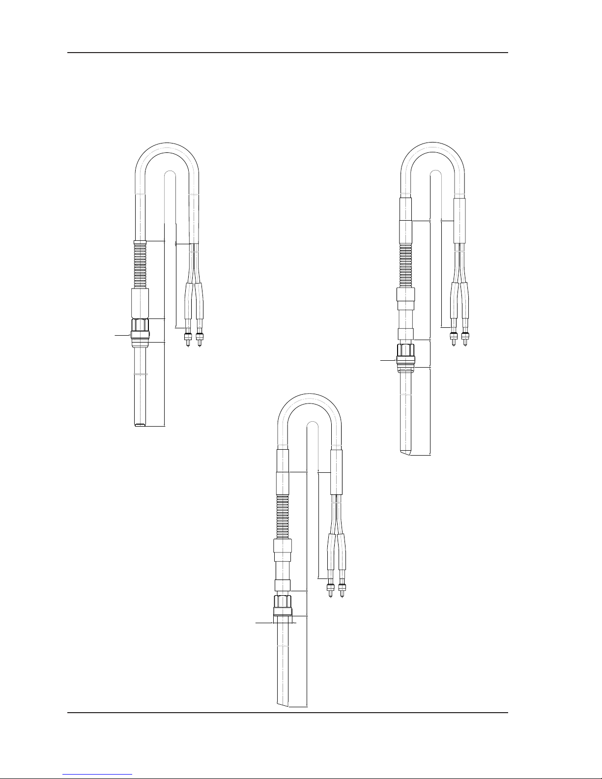
6. Dimensional drawings
InPro®8200/S(H) InPro®8100/S
InPro®8050
Pg13.5
122
26 1000 +/-30 4900 +/-50
300 +/-10
InPro8100/S
Typ a
120 mm 122 mm
205 mm 207 mm
297 mm 299 mm
407 mm 409 mm
Pg13.5
31
a
O-SMA
1900 +/-301000 +/-30
300 +/-10
InPro8200/S(H)/Epoxy
InPro8200/S/Kalrez®-FDA
Typ a
120 mm 120 mm
205 mm 205 mm
297 mm 297 mm
407 mm 406.5 mm
O-SMA
2350 +/-30520 +/-30
350 +/-10
27
a
Pg13.5
InPro®8000 Series 17
© 01/04 Mettler-Toledo GmbH, CH-8606 Greifensee InPro®8000 Series
Printed in Switzerland 52 800 247
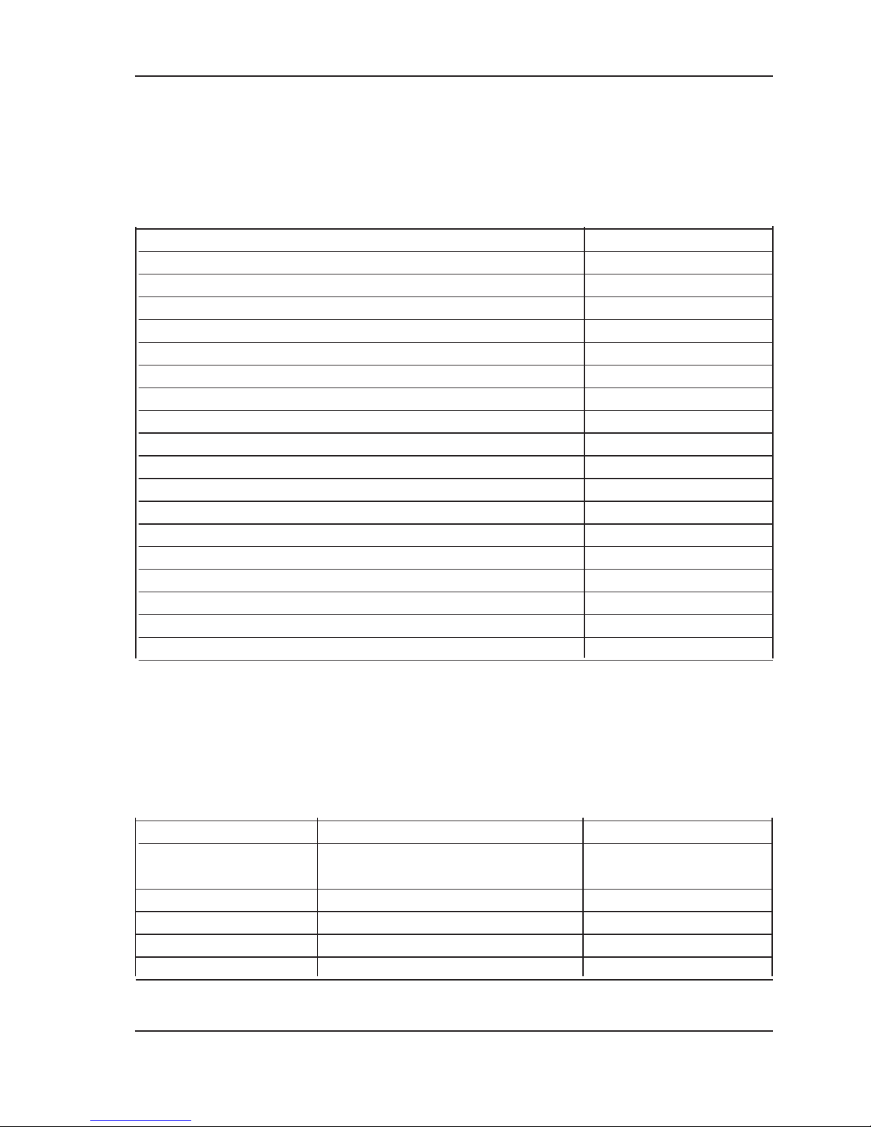
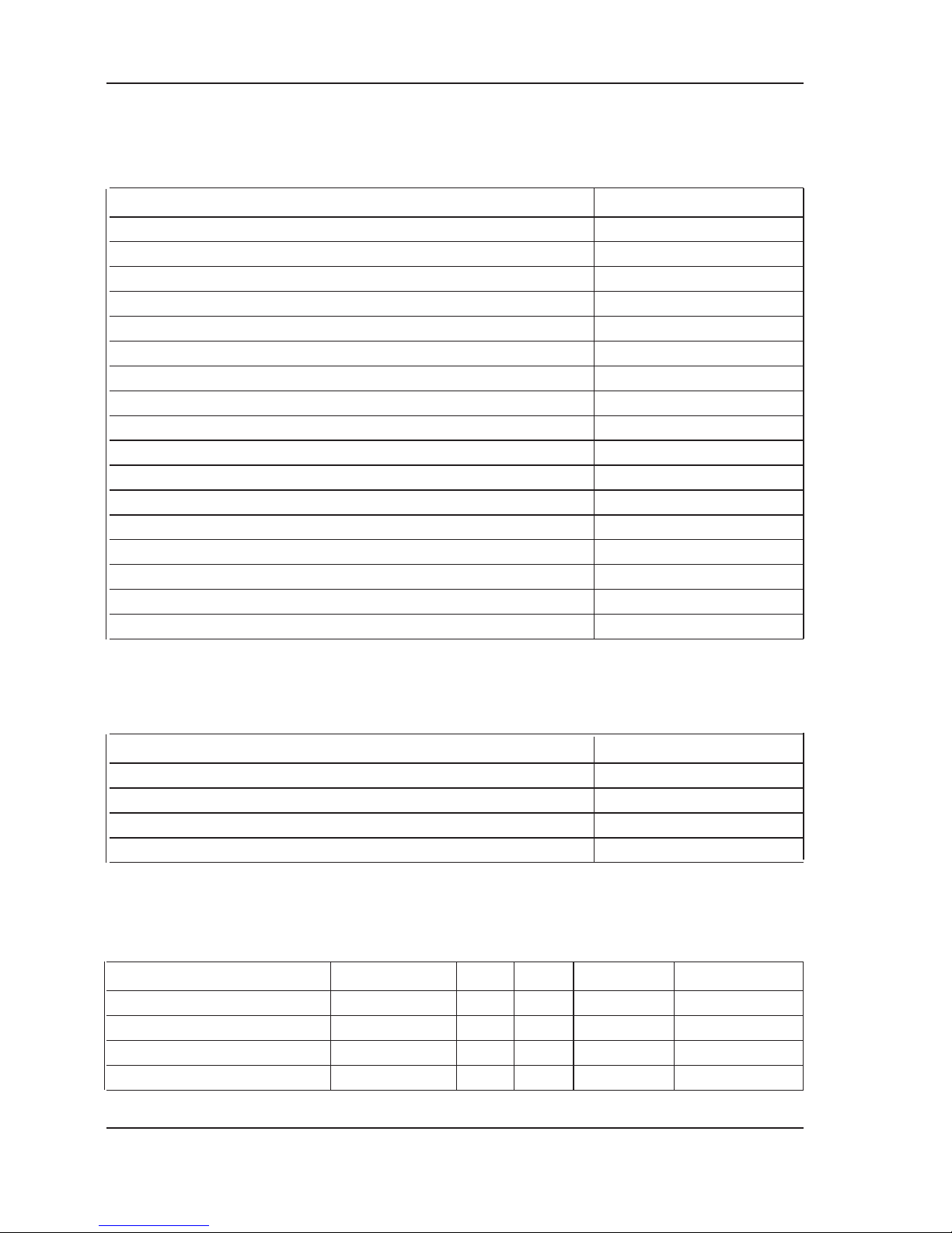
7. Ordering information
7.1 Sensors
Designation Order no.
InPro8050 52 800 209
InPro8100/S/120 52 800 205
InPro8100/S/205 52 800 206
InPro8100/S/297 52 800 207
InPro8100/S/407 52 800 208
InPro8200/S/Epoxy/120 52 800 216
InPro8200/S/Epoxy/205 52 800 217
InPro8200/S/Epoxy/297 52 800 218
InPro8200/S/Epoxy/407 52 800 219
InPro8200/H/Epoxy/120 52 800 220
InPro8200/H/Epoxy/205 52 800 221
InPro8200/H/Epoxy/297 52 800 222
InPro8200/H/Epoxy/407 52 800 223
InPro8200/S/Kalrez-FDA/120 52 800 224
InPro8200/S/Kalrez-FDA/205 52 800 225
InPro8200/S/Kalrez-FDA/297 52 800 226
InPro8200/S/Kalrez-FDA/407 52 800 227
InPro8200/H/Kalrez-FDA/407* 52 800 215
* shaft material Hastelloy C22
7.2 Accessories
O-rings, for all sensors:
Standard O-ring Additional O-rings Order no.
Viton®-FDA 20 302 1000
(10.77 x 2.62 mm)
Silicon-FDA (10.77 x 2.62 mm) 20 301 1136
Kalrez®(10.77 x 2.62 mm) 20 304 1000
Kalrez®-FDA (10.77 x 2.62 mm) 20 304 1034
EPDM-FDA (10.77 x 2.62 mm) 20 303 1206
18 InPro®8000 Series
InPro®8000 Series © 01/04 Mettler-Toledo GmbH, CH-8606 Greifensee
52 800 247 Printed in Switzerland
Fiber optic cable extensions including two couplings, for all sensors:
Designation Order no.
Fiber-Kit, 3 m (10 ft) 52 800 228
Fiber-Kit, 5 m (15 ft) 52 800 229
Fiber-Kit, 6 m (18 ft) 52 800 230
Fiber-Kit, 10 m (30 ft) 52 800 231
Fiber-Kit, 15 m (45 ft) 52 800 232
Fiber-Kit, 20 m (60 ft) 52 800 233
Fiber-Kit, 25 m (75 ft) 52 800 234
Fiber-Kit, 30 m (100 ft) 52 800 235
Fiber-Kit, 40 m (130 ft) 52 800 236
Fiber-Kit, 45 m (150 ft) 52 800 172
Fiber-Kit, 50 m (165 ft) 52 800 237
Fiber-Kit, 65 m (200 ft) 52 800 238
Fiber-Kit, 75 m (230 ft) 52 800 177
Fiber-Kit, 90 m (275 ft) 52 800 239
Fiber-Kit, 100 m (330 ft) 52 800 154
Fiber-Kit, 125 m (380 ft) 52 800 158
Fiber-Kit, 170 m (520 ft) 52 800 196
Additional accessories, for all sensors:
Designation Order no.
«CaliCap» 52 800 210
Couplings 52 800 240
Coupling box IP65 52 800 241
Swagelok adapter NPT1/2"
1)
52 800 242
1)
only to be used with InPro®8200/S/Epoxy Sensors for pressure range 0…60 bar (0…870 psi)
Housings for InPro®8100 and InPro®8200 (examples):
Designation Material H a O-ring Order no.
InFit761-25 CP/70/4435/Vi DIN1.4435 70 120 Viton
®
00 761 3042
InFit761-25 CP/70/C22/Vi Hastelloy C22 70 120 Viton
®
00 761 3105
InFit761-25BTB/70 DIN1.4435 70 120 Silicon-FDA 00 761 3093
InFit761-25CIP/70 3.1B DIN1.4435 70 120 Silicon-FDA 52 400 491
 Loading...