

Mettler Toledo InPro 7250 Instruction Manual
InPro®7250
52 002 799
InPro®7250 Series
Inductive Conductivity Sensors
Induktive Leitfähigkeitsmesszellen
Sondes de conductivité inductive
Instruction Manual
Bedienungsanleitung
Instructions d’utilisation
1258

2 InPro®7250 Series
© 01/2016 Mettler-Toledo GmbH CH -8606 Greifensee
Printed in Switzerland 52 002 799
English Page 3
Deutsch Seite 25
Français Page 49

InPro®7250 Series 3
© 01/2016 Mettler-Toledo GmbH CH -8606 Greifensee
Printed in Switzerland 52 002 799
InPro®7250 Series
Instruction Manual
© It is forbidden to reprint this Instruction Manual in whole or part.
No part of this manual may be reproduced in any form, or modified,
copied or distributed using electronic systems, in particular in the
form of photocopies, photographs, magnetic or other recordings,
without written consent of Mettler-Toledo GmbH, Process Analytics,
CH- 8902 Urdorf, Switzerland.
All rights reserved, in particular reproduction, translation
and patenting/registration.

4 InPro®7250 Series
© 01/2016 Mettler-Toledo GmbH CH -8606 Greifensee
Printed in Switzerland 52 002 799
Contents
1 Introduction ..................................................5
2 Important notes ............................................6
2.1 Notes on operating instructions................................6
2.2 Intended use..........................................................6
2.3 Safety instructions ..................................................7
2.4 Use in hazardous zones..........................................8
2.5 Ex-classification ATEX............................................8
2.5.1 Introduction ..........................................................8
2
.5.2 Rated data ............................................................8
2.5.3. Special conditions for safe use ................................9
2.5.4 ATEX certificate ....................................................10
2.5.5 IECEx Certificate of Conformity ..............................12
2.6 Ex-classification FM Approved ..............................14
2.7 Declaration of conformity ......................................15
3 Product description ....................................16
3.1 General information..............................................16
3.2 Principle ............................................................16
3.3 Sensor identification ............................................16
3.4 Sensor applications..............................................17
4 Installation, operation and maintenance ......18
4.1 Sensor installation................................................18
4.2. Connection of the sensor ......................................20
4.3 Flange installation................................................20
4.4 Bushing installation..............................................21
4.5 Immersion installation with an InDip 550 Ind ..........21
4.6 Sanitary installation..............................................22
4.7 Disposal ............................................................22
5 Product specifications ................................23
5.1. Sensor specifications............................................23
6 Ordering information ..................................24
6.1. Sensors ..............................................................24
6.2 Spare parts..........................................................24
6.3 Process Connections and Accessories ....................24
6.4 Transmitter M700(x), module Cond Ind 7700(x) ....25
6.5 Transmitter M400, (4-wire Transmitter) ..................25

InPro®7250 Series 5
© 01/2016 Mettler-Toledo GmbH CH -8606 Greifensee
Printed in Switzerland 52 002 799
1 Introduction
T
hank you for buying the InPro 7250 Series sensor from
METTLER TOLEDO.
The construction of the InPro 7250 Series sensors
employs leading edge technology and complies with
safety regulations currently in force. Notwithstanding
this, improper use could lead to hazards for the user or
a third-party, and/or adverse effects on the plant or other
equipment. Therefore, the operating instructions must
be read and understood by the persons involved before work is started with the sensor.
The instruction manual must always be stored close at
h
and, in a place accessible to all people working with
the sensor.
If you have questions, which are not or insufficiently
answered in this instruction manual, please contact your
METTLER TOLEDO supplier. They will be glad to assist
you.
6 InPro®7250 Series
© 01/2016 Mettler-Toledo GmbH CH -8606 Greifensee
Printed in Switzerland 52 002 799
2 Important notes
2.1 Notes on operating instructions
T
hese operating instructions contain all the information
needed for safe and proper use of the InPro 7250 Series
sensor.
T
he operating instructions are intended for personnel
entrusted with the operation and maintenance of the
sensors. It is assumed that these persons are familiar
with the equipment in which the sensor is installed.
Warning notices and symbols
This instruction manual identifies safety instructions and
additional information by means of the following
symbols:
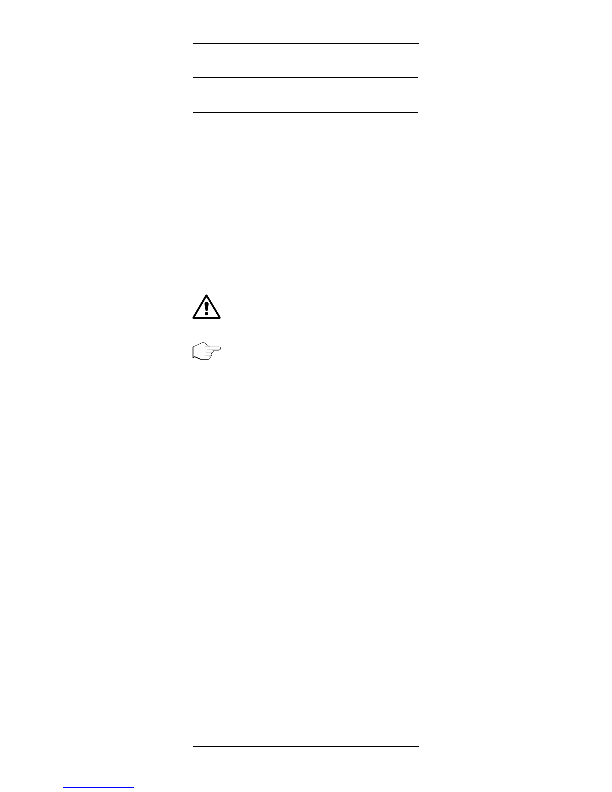
This symbol draws attention to safety instructions and
warnings of potential danger which, if neglected, could
result in injury to persons and/or damage to property.
This symbol identifies additional information and
instructions which, if neglected, could lead to defects,
inefficient operation and possible loss of production.
2.2 Intended use
The sensors InPro 7250 Series are intended to be used
to measure conductivity and concentration of liquids, in
accordance with the data in this instruction manual. Any
use of these sensors which differs from or exceeds the
scope of use described in this instruction manual will be
regarded as inappropriate and incompatible with the
intended purpose.
The manufacturer/supplier accepts no responsibility
whatsoever for any damage resulting from such improper
use. The risk is borne entirely by the user/operator.
Other prerequisites for appropriate use include:
– compliance with the instructions, notes and require-
ments set out in this instruction manual.
– acceptance of responsibility for regular inspection,
maintenance and functional testing of all associated
components, also including compliance with local
operational and plant safety regulations.
– compliance with all information and warnings given
in the documentation relating to the products used in
conjunction with the sensor (housings, transmitters,
etc.).
– observance of all safety regulations governing the
equipment in which the sensor is installed.

InPro®7250 Series 7
© 01/2016 Mettler-Toledo GmbH CH -8606 Greifensee
Printed in Switzerland 52 002 799
– correct equipment operation in conformance with the
p
rescribed environmental and operational conditions,
and admissible installation positions.
–
consultation with METTLER TOLEDO Process Ana lytics in the event of any uncertainties.
2.3 Safety instructions
– The plant operator must be fully aware of the potential
risks and hazards attached to operation of the
particular process or plant. The operator is responsible for correct training of the workforce, for signs and
markings indicating sources of possible danger,
and for the selection of appropriate, state-of-the-art
instrumentation.
– It is essential that personnel involved in the commis-
sioning, operation or maintenance of these sensors
or of any of the associated equipment (e.g. housings,
transmitters, etc.) be properly trained in the process
itself, as well as in the use and handling of the
associated equipment. This includes having read and
understood this instruction manual.
– The safety of personnel as well as of the plant itself is
ultimately the responsibility of the plant operator. This
applies in particular in the case of plants operating in
hazardous zones.
– The conductivity sensors and associated components
have no effect on the process itself and cannot influence it in the sense of any form of control system.
– Maintenance and service intervals and schedules
depend on the application conditions, composition of
the sample media, plant equipment and significance
of the safety control features of the measuring system.
Processes vary considerably, so that schedules,
where such are specified, can only be regarded as
tentative and must in any case be individually
established and verified by the plant operator.
– Where specific safeguards such as locks, labels, or
redundant measuring systems are necessary, these
must be provided by the plant operator.
– A defective sensor must neither be installed nor put
into service.
– Only maintenance work described in this operating in-
struction may be performed on the sensors.
– No modifications to the sensors and the accessories
are allowed. The manufacturer accepts no respon sibility for damages caused by unauthorised modi fications. The risk is borne entirely by the user.

8 InPro®7250 Series
© 01/2016 Mettler-Toledo GmbH CH -8606 Greifensee
Printed in Switzerland 52 002 799
2.4 Use in hazardous zones
F
or an installation in hazardous zones please read the
guidelines following hereafter:
Ex-classification ATEX:
II 1/2G Ex ia IIC T6/T5/T4/T3 Ga/Gb
Number of the test certificate:
SEV 15 ATEX 0123
IECEx SEV 15.0011X
2.5 Ex-classification ATEX
2.5.1 Introduction
According to Directive 94/9/EC (ATEX 95) Appendix I,
InPro 725X/*/*/* conductivity sensors are devices of
equipment group II, category 1/2G which can be used
in zone 0/1 or 1/2 or 1 or 2 as well as gas groups IIA,
IIB and IIC, which are potentially explosive due to combustible substances in the temperature classes T3 to T6.
For use/ installation, the requirement of
EN/IEC 60079-14 must be observed.
The conductivity measuring circuit and temperature
measuring circuit are part of a common intrinsically safe
system and are for operation connected to a separately
certified transmitter.
The conductivity measuring circuit and temperature
measuring circuit as part of an intrinsically safe system
are isolated from conductive housing parts up to a
maximum rated voltage of 30 V.
The sensors can be installed with different process
adapters (flange, threaded bushes) permanently in pipes
or tanks.
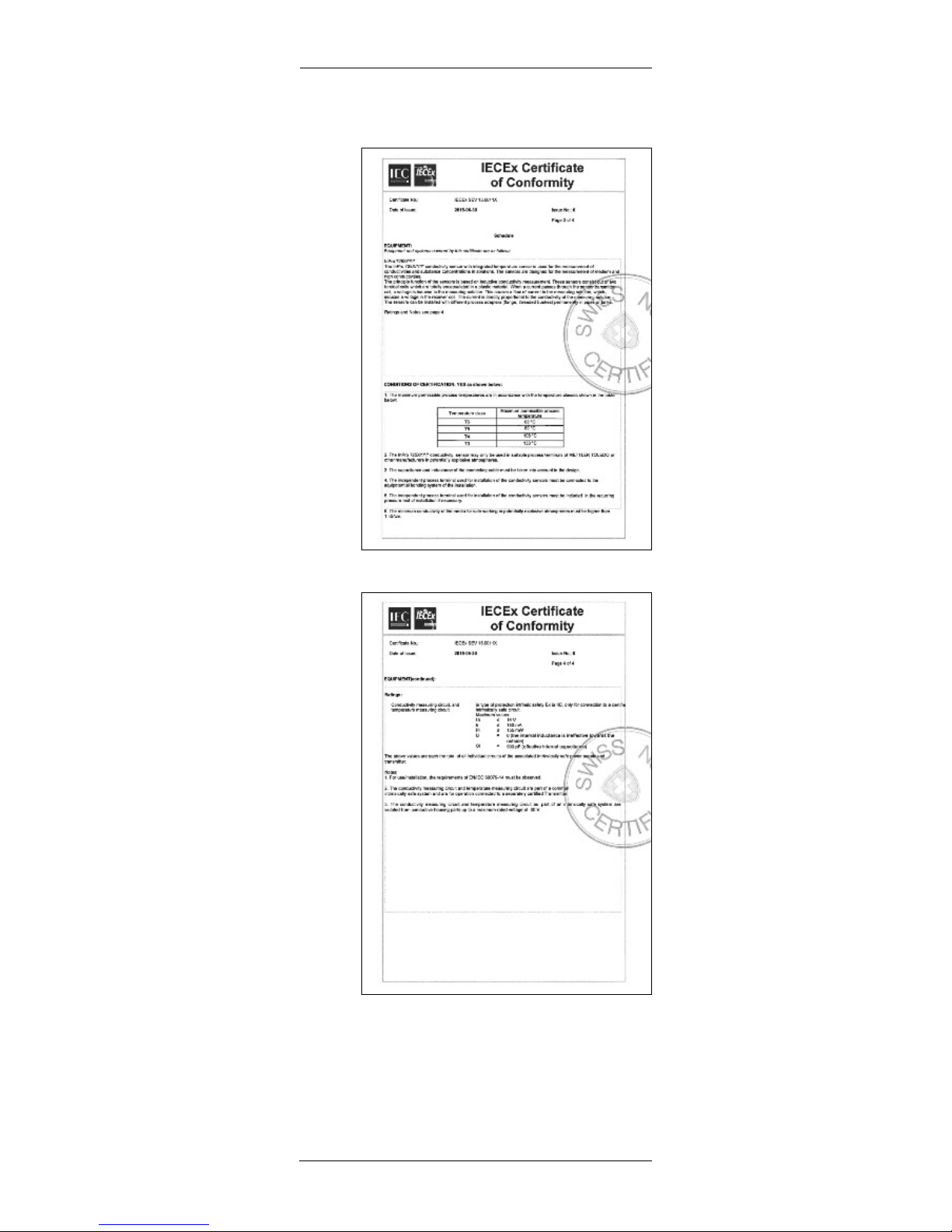
2.5.2 Rated data
Conductivity measuring circuit, and temperature measuring circuit1:
In type of protection intrinsic safe Ex ia IIC, only for
connection to a certified intrinsically safe circuit.
Maximum values:
U
i
≤ 16 V, Ii≤ 150 mA, Pi≤ 155 mW
Li= 0 (the internal inductance is ineffective towards the
outside)
C
i
= 900 pF (effective internal capacitance)
The above values are each the total of all individual circuits of the associated intrinsically safe power supply
and transmitter.

InPro®7250 Series 9
© 01/2016 Mettler-Toledo GmbH CH -8606 Greifensee
Printed in Switzerland 52 002 799
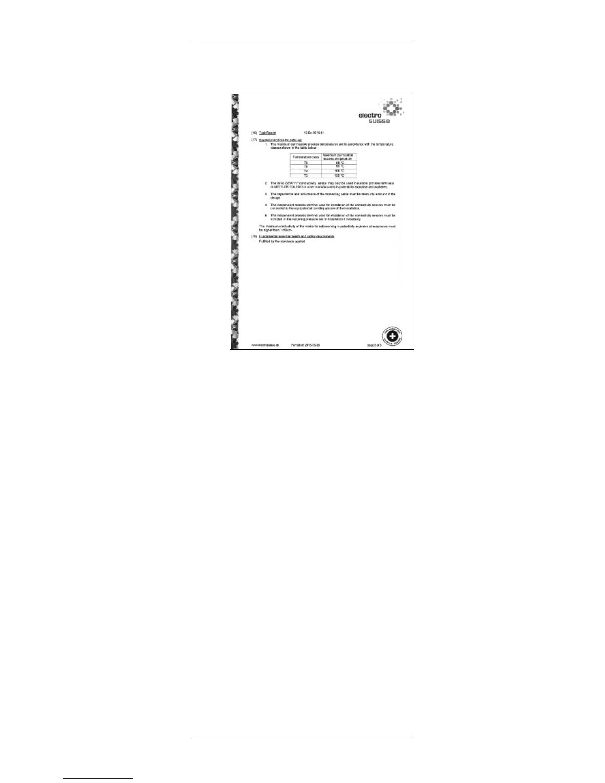
2.5.3. Special conditions for safe use
1. The maximum permissible process temperatures are
in accordance with the temperature classes shown in
the table below:
Temperature class Maximum permissible
process temperature
T6 68 °C
T5 80 °C
T4 108 °C
T3 130 °C
2
. The InPro 725X/*/*/* conductivity sensors may only
be used in suitable process terminals of METTLER
TOLEDO or other manufacturers in potentially explosive atmospheres.
3. The capacitance and inductance of the connecting
cable must be taken into account in the design.
4. The independent process terminal used for installa -
tion of the conductivity sensors must be connected to
the equipotential bonding system of the installation.
5. The independent process terminal used for installa-
tion of the conductivity sensors must be included
in the recurring pressure test of the installation if
necessary.
6. The minimum conductivity of the media for safe
working in potentially explosive atmospheres must be
higher than 1 nS/cm.
10 InPro®7250 Series
© 01/2016 Mettler-Toledo GmbH CH -8606 Greifensee
Printed in Switzerland 52 002 799
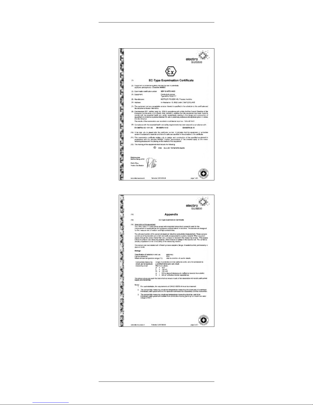
2.5.4 ATEX certificate
Page 1 of 3
Page 2 of 3
InPro®7250 Series 11
© 01/2016 Mettler-Toledo GmbH CH -8606 Greifensee
Printed in Switzerland 52 002 799
Page 3 of 3

12 InPro®7250 Series
© 01/2016 Mettler-Toledo GmbH CH -8606 Greifensee
Printed in Switzerland 52 002 799
2
.5.5 IECEx Certificate of Conformity
Page 1 of 4
Page 2 of 4
InPro®7250 Series 13
© 01/2016 Mettler-Toledo GmbH CH -8606 Greifensee
Printed in Switzerland 52 002 799
P
age 3 of 4
Page 4 of 4
14 InPro®7250 Series
© 01/2016 Mettler-Toledo GmbH CH -8606 Greifensee
Printed in Switzerland 52 002 799
2.6 Ex-classification FM Approved
I
S/ I, II, III /1/ABCDEFG /T6 Ta = 60 °C
FM control drawing:
Non-Hazardous Location
Hazardous (Classified) Location
Class I, Division 1, Groups A, B, C and D
Class II, Division 1, Groups E, F and G
Class III, Division 1
T6 Ta= 60 C
Any FMRC A ppro ved Sin gle
Mult i-Chan nel Barrier or App aratus
Prob e
Mettl er-Toledo GmbH
Proce ss Ana lytics
CH-89 02 Urd orf
10/02 /2005 M. Bles sing
15/07 /2005 F. Trefz
FM control drawing Cond Ind
Wir b ehalte n uns a lle Rec hte an diesem Dokume nt und an alle n Beila gen vo r. Der Em pfänge r anerk ennt
diese Recht e und w ird die genann ten Unt erlage n nicht ohne u nsere v orgäng ige sch riftlic he Erm ächtigu ng
Dritt en zug änglich machen oder a usserha lb des Zwecke s verwe nden, z u dem sie ihm überge ben wor den sin d.
Enti ty Par amet ers:
V
t
=16 V, I
t
=150 mA, P
max
= 155 mW
C
i
= 900 pF, L
i
0.3 mH
Note s:
WARN ING: subst itut ion of compon ents may inpai r in trinsic safet y.
1. No rev isio n to th is draw ing is per mitted withou t FM RC appr oval
2. V
max
> V
t
; I
max
> I
t
; (C
i
of all lo ops + C cab le) < C
a
; (L
i
of all lo ops + L cab le) < L
a
; P
max
or P
i
> P
0
3. Single Mul ti-Chan nel IS Barrie r or Appara tus mu st b e FMRC Approv ed
5. Instal lati on must be in accord ance with A rticle 500 of the NEC
®
(ANS I/NFPA 70)
and A NSI/ ISA RP1 2.6.
4. Single Mul ti-Chan nel IS Barrie r or Appara tus ma nufa cturer' s cont rol draw ings
must be f ollowed when i nstall ing the Sys tem. I S Ba rrier o r Equi pmen t ma y be
insta lled within the Ha zardou s (C lassifie d) loc atio n for w hich i t is app roved.
InPro®7250 Series 15
© 01/2016 Mettler-Toledo GmbH CH -8606 Greifensee
Printed in Switzerland 52 002 799
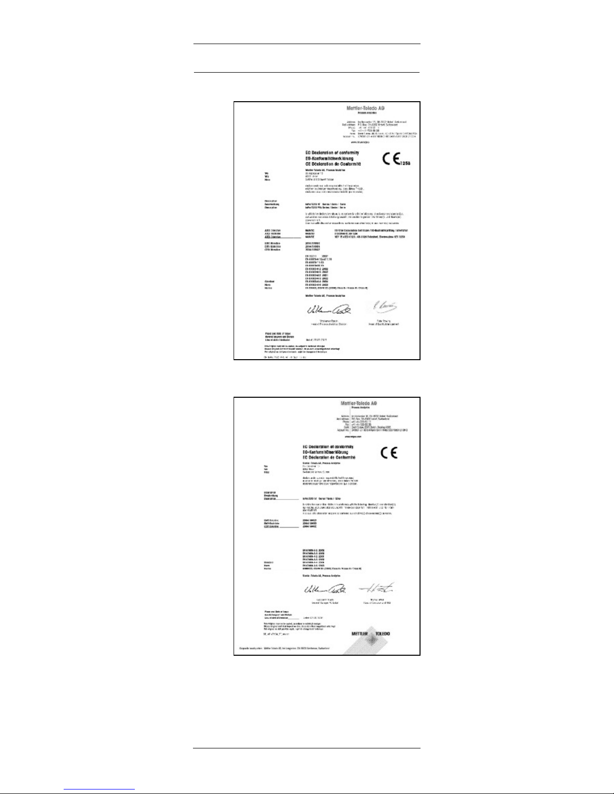
2.7 Declaration of conformity
I
nPro 725X HT
InPro 725X ST

16 InPro®7250 Series
© 01/2016 Mettler-Toledo GmbH CH -8606 Greifensee
Printed in Switzerland 52 002 799
3 Product description
3.1 General information
T
he conductivity sensors InPro 7250 Series with inte grated temperature sensor are intended to be used to
measure conductivity and concentrations of liquids. The
sensor is designed for the measurement of medium and
h
igh conductivity values.
3.2 Principle
The sensors InPro 7250 Series measure an induced
current in a loop of solution.
Two toroidally wound coils are encapsulated in close
proximity within the sensor which is immersed in the
solution. An AC signal, applied to one toroidal coil,
in duces a current in the second coil which is directly
proportional to the conductance of the solution.
3.3 Sensor identification
Type designation
A sensor can be identified by the article number and the
model name on the label located on the cable.
InPro 7250xx/yy/zz
xx: Type of sensor
ST = Sensor for temperature up to 100 °C
(212 °F), without EX approval
HT = Sensor for temperature up to 180 °C,
(356 °F) with EX approval
PFA = Sensor in PFA* for Temperatures up to
125°C (257°F)
yy: type of the integrated temperature sensor
zz: cable length
Serial number
The serial number is located on the end of the mounting
thread.
Sensor certificate number
The labels located on the sensor cable provide the
information about the sensor certifications.
*PFA: Perfluoralkoxy-Copolymer
InPro®7250 Series 17
© 01/2016 Mettler-Toledo GmbH CH -8606 Greifensee
Printed in Switzerland 52 002 799
Figure 1: Sensor identification
3.4 Sensor applications
InPro 7250 ST
This sensor may be used for most routine applications
like conductivity measurement in industrial wastewater
systems. For applications at higher temperatures and for
use in hazardous areas the sensor InPro 7250 HT is the
preferred alternative.
InPro 7250 HT
The InPro 7250 Series sensor is suitable for the majority of all electrodeless conductivity applications. Its
compact size enables it to be mounted in a multitude of
methods, including insertion (flange, bushing), and
immersion. Typical applications include salinity and
brine measurements, steel pickling, scrubbing towers,
ion exchange regeneration, plating baths, rinse water,
caustic metal cleaning, and textile measurements in
scouring, mercerizing, and carbonizing baths.
InPro 7250 PFA
This sensor is particularly suited for heavy-duty chemical
applications such as Oleum (highly concentrated sulfuric acid), as well as applications in the pharmaceutical
and biopharmaceutical industry (CIP skids, acid and base concentration).
Notes:
– PEEK is a thermoplastic material with excellent
strength and chemical resistance properties over a
wide range of process temperatures and pressures.
– PEEK material displays excellent chemical resis-
tance to most aqueous solutions of acids, bases, and
salts. It is also excellent for organic solvents such as
toluene, ethyl acetate, acetone, gasoline, and carbon
tetrachloride. It is not recommended for sulfuric or
nitric acid solutions above 70 %, nor is it recommended for Oleum applications.
– PFA is a type of fluorcarbons with similar properties
as PTFE. PFA is resistant against nearly all chemicals
and has a high temperature resistance. The PFA quality used here does not contain glass fibres (virgin
PFA).
S
erial number
A
rticle number and
model name
S
ensor
certificate number
18 InPro®7250 Series
© 01/2016 Mettler-Toledo GmbH CH -8606 Greifensee
Printed in Switzerland 52 002 799
4 Installation, operation
and maintenance
4.1 Sensor installation
The sensor shaft is equipped with a conical G3/4"
mounting thread. The installation of the sensor is made
by threaded bushes or flanges. The process area is
sealed perfectly with flat gasket and an O-ring.
Note: When mounted in-line, the sensor should
be in stalled centered to avoid pipe wall effects. If there is
less than 30 mm (1.18 inch) spacing between sensor
and pipe, a product calibration with a sensor built in
the process is re commended to meet the specified
accuracies.
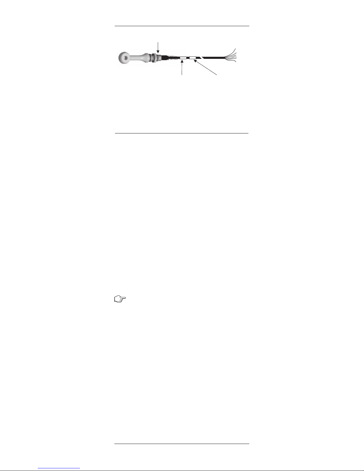
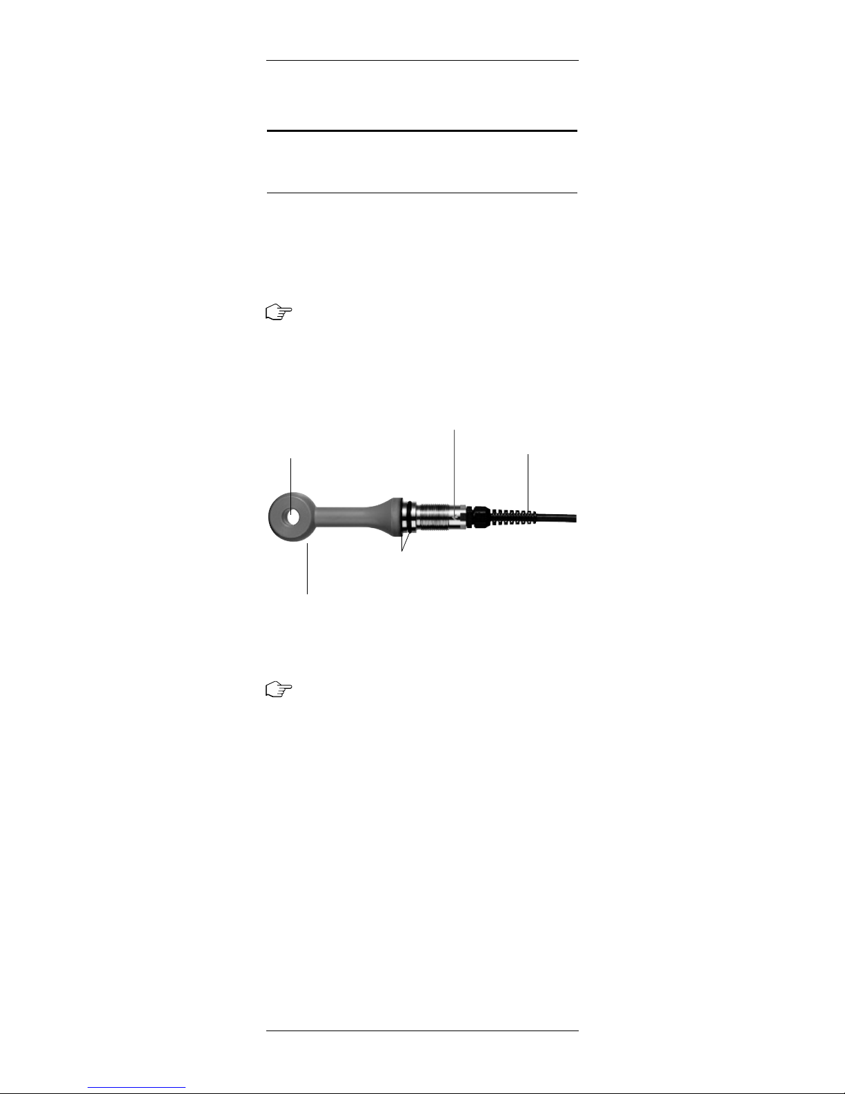
Figure 2: Sensor overview
Note: Proper installation of the sensor is important for
efficient and accurate operation. For all applications and
sensor configurations, mounting arrangements must be
located so that:
– Sample at the sensing area is representative of the
solution.
– Solution circulates actively and continuously past the
sensing area.
– Position and orientation of the sensor does not trap
air bubbles within sensing area.
– Deposits of sediment or other foreign material do not
accumulate within the sensing area. If cable is in stalled in a conduit (recommended), either flexible
conduit should be used or some other provision
made for removal of sensor from the process.
Bore
Arrow for the
sensor direction
Cable cap
Sensor doughnut
Flat gasket and O-ring
for safe process sealing
A
InPro®7250 Series 19
© 01/2016 Mettler-Toledo GmbH CH -8606 Greifensee
Printed in Switzerland 52 002 799
Notes:
–
The sensors of the InPro 7250 Series are marked with
an arrow, which indicates the flat (upstream) face of
the sensor, for correct installation in a pipe or a tank.
The marking is at the upper end of the sensor mount
ing thread (see Figure 2).
W
arning!
Incorrect O-ring position or a damaged O-ring could
result in process leakage, causing injury to personnel.
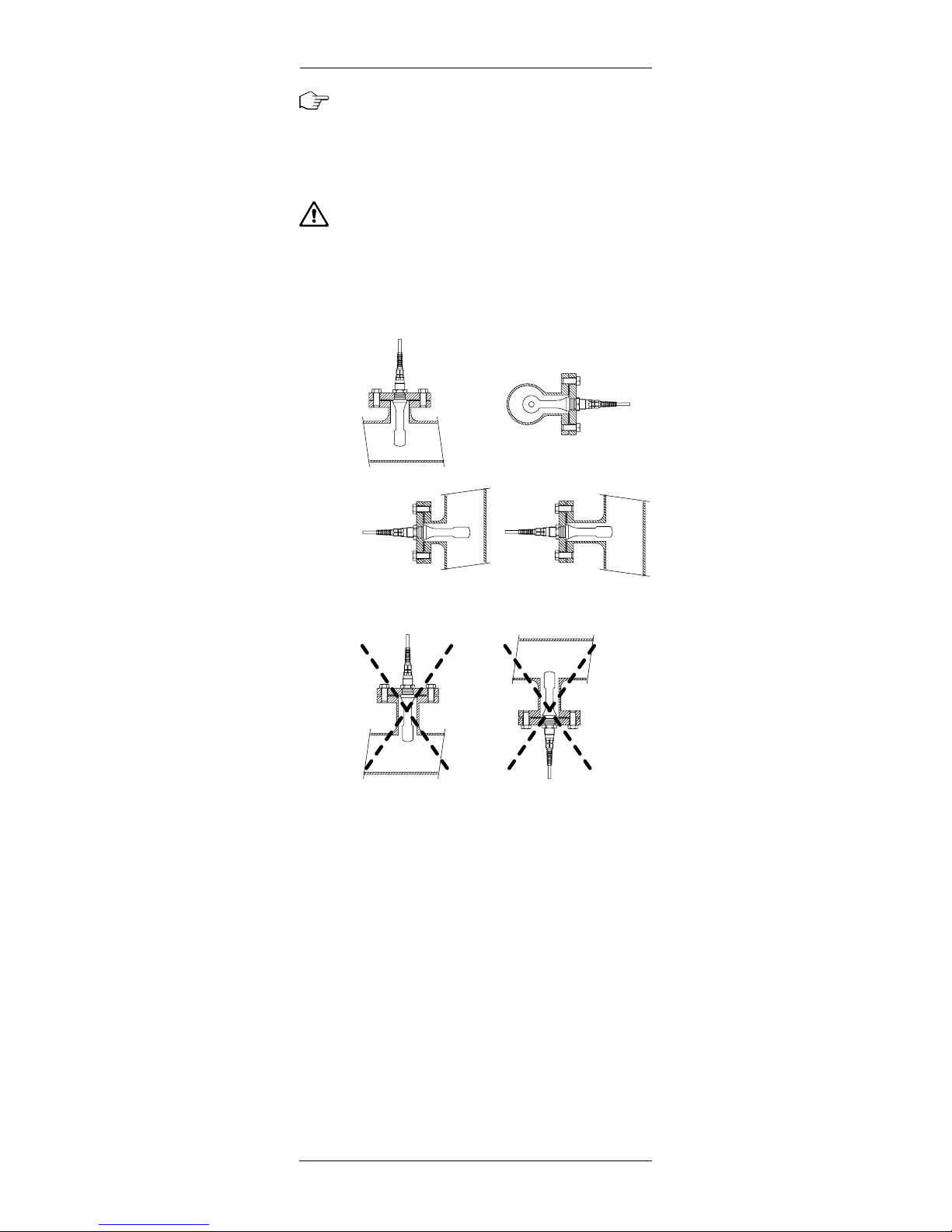
Figure 3:
Installation examples of the InPro7250 sensor
Air entrapment Solid deposits
Recommended
Not recommended!
20 InPro®7250 Series
© 01/2016 Mettler-Toledo GmbH CH -8606 Greifensee
Printed in Switzerland 52 002 799
4.2. Connection of the sensor
C
able configuration
InPro 7250 ST / PFA InPro 7250 HT
receive hi black red
receive lo red yellow
send lo brown violet
send hi blue black
RTD green green
R
TD white white
RTD sense grey grey
shield green/yellow green/yellow
Transmitter connection
The sensors InPro 7250 Series are suitable for connection to the following METTLER TOLEDO transmitters:
M 700(X), Module Cond Ind 7700(X):
«Premium line» transmitter,
modular measuring system
M400, Type 1 Cond Ind:
«Advanced Line» transmitter, 4-wire
Note: In order to connect the sensor with the transmitter,
please consider the instruction manual of the METTLER
TOLEDO transmitter.
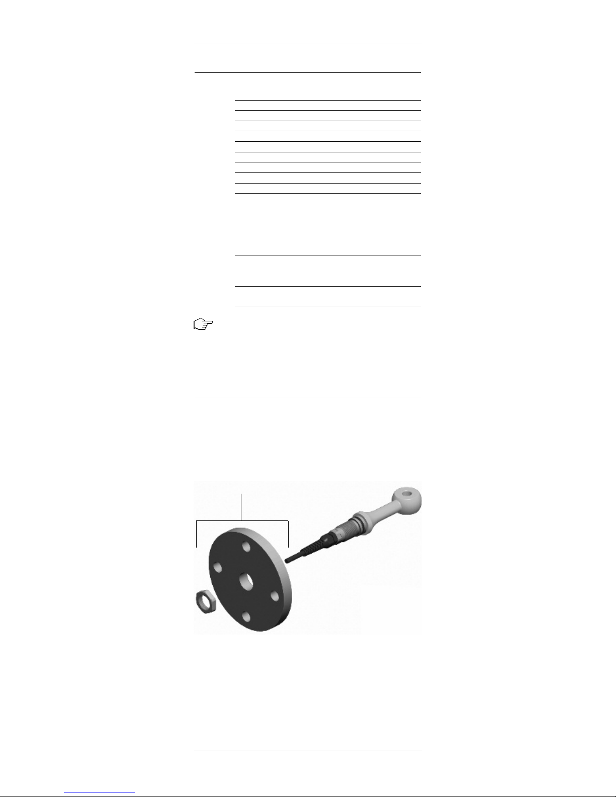
4.3 Flange installation
METTLER TOLEDO flanges are used for permanent installations in pipelines and tanks. Flanges are used with
electrodeless conductivity sensors in systems using
DN50 or 2-inch and larger process piping. Flanges are
provided complete with locknut.
Figure 4: Flange installation
Flange with locknut

InPro®7250 Series 21
© 01/2016 Mettler-Toledo GmbH CH -8606 Greifensee
Printed in Switzerland 52 002 799
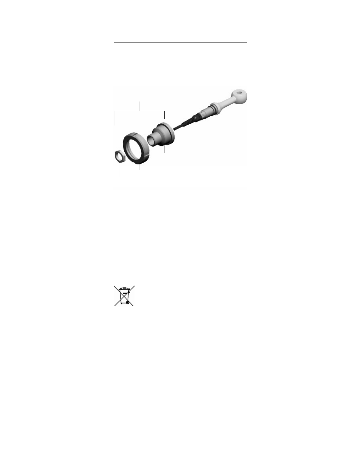
4.4 Bushing installation
S
upplied METTLER TOLEDO bushings are used for in stallations in pipelines and tanks and are provided
complete with locknut.
Figure 5: Bushing installation
4.5 Immersion installation with an
InDip 550 Ind
For open tanks or inlet channel the sensor can be installed in an immersion housing InDip 550Ind.
Figure 6: Installation with an immersion housing
«InDip 550Ind»
Bushing with
locknut
4.6 Sanitary installation
M
ETTLER TOLEDO offers a dairy adapter according to DIN
11851 (DN50) as well as an aseptic adapter DIN
11864-1 (DN50) for the inductive sensors of the InPro
7250 series.
Figure 7: Installation with sanitary adapters
4.7 Disposal
The sensors described in this manual usually cannot be
repaired. Their disposal is to the responsability of the
user. Sensors contain electronic components (coils,
cables) that require special disposal without any health
hazard for humans, and with no risk of harm for the
environment.
Disposal (Directive 2002/96/EC of January 27, 2003):
Please observe the applicable local or national regu lations concerning the disposal of "waste electrical and
electronic equipment".
22 InPro®7250 Series
© 01/2016 Mettler-Toledo GmbH CH -8606 Greifensee
Printed in Switzerland 52 002 799
Adapter with
accessories
Locknut
Ringnut
Adapter

5 Product specifications
5.1. Sensor specifications
InPro 7250 ST/HT InPro 7250 PFA
Measuring principle inductive inductive
Sensor data
Measuring range 0…2000 mS/cm 0…2000 mS/cm
Measurement ST: ± (0.5 % of meas. ± (0.5% of meas.
value deviation value + 25 µS) value + 25 µS)
HT: ± (0.5% of meas.
value + 1 µS)
Cell factor nominal
1
)
2.175 2.30
Transfer ratio 120 120
Temperature sensor Pt 1000 Pt 1000
Temperature
response (t90) approx. 5 min approx. 5 min
Ambient conditions
2
)
Process temperature ST: –20 °C…+100 °C –20 °C…+125 °C
(general purpose) (–4 °F…+212 °F) (–4…+257 °F)
HT: –20 °C…+180 °C
(–4…+356 °F)
Process temperature ST: – –20 °C…+125 °C
(In Ex-classified HT: –20 °C…+130 °C (–4…+257 °F)
area installation) (–4…+266 °F)
Process ST: max. 8 bar max. 16 bar
pressure
3
)
(max. 116 psi) (max. 232 psi)
HT: max. 20 bar
(max. 290 psi)
Sensor materials
Sensor PEEK PFA
(medium wetted) 4) glass-fiber reinforced not glass-filled
(GF30)
Sensor mounting
thread (G 3/4") stainless steel stainless steel
O-ring Viton® FEP
Flat gasket Viton® PTFE
Cable
Type ST: single coaxial cable simple coaxial cable
HT: double coaxial cable
Cable jacket ST: PVC PVC
HT: silicone
Available cable lengths 3, 5 and 10 m 3, 5 and 10 m
(9.8, 16.4 (9.8, 16.4
and 32.8 ft) and 32.8 ft)
Approvals and certificates
ATEX ST: – –
HT: • •
FM ST: – –
HT: • •
Quality/End control • •
1)
This value depends on the installation.
The exact value must be determined with a calibration.
2)
The combination of high pressure, high temperature and/or
aggressive process medium reduces the sensor life span.
3)
Depending on the installation.
4)
This material is not FDA listed.
InPro®7250 Series 23
© 01/2016 Mettler-Toledo GmbH CH -8606 Greifensee
Printed in Switzerland 52 002 799
 Loading...