

Mettler Toledo InPro 7005-VP, InPro 7001/120-VP, InPro 7002-VP, InPro 7001/225-VP, InPro 7000-VP Instruction Manual
InPro 7000-VP Series
2-electrode conductivity sensors
2-Pol-Leitfähigkeits-Messzellen
Sondes de conductivité à 2 électrodes
Instruction manual
Bedienungsanleitung
Manuel d’utilisation
InPro 7000-VP Series
52 002 091

English Page 3
Deutsch Seite 19
Français Page 35

InPro 7000-VP Series 3
InPro 7000-VP Series
2-electrode conductivity sensors
Instruction manual
Subject to technical changes without prior notice.
© It is strictly forbidden to reprint this instruction manual or any parts thereof without
the written permission of Mettler-Toledo GmbH, Process Analytics, Im Hackacker 15,
8902 Urdorf, Switzerland. No section or excerpt whatsoever may be reproduced or with
the assistance of electronic systems be edited, duplicated or distributed, in particular in
the form of photocopies, photographs, magnetic media or other recording methods. All
rights reserved, especially the right of duplication and translation as well as in regard
to patent and registration rights.
InPro is a registered trademark of the Mettler Toledo Group in Switzerland and a further
twelve countries.
Mettler-Toledo GmbH, 8606 Greifensee, Switzerland
© 02 / 2017 Mettler-Toledo GmbH, CH - 8606 Greifensee InPro 7000-VP Series
Printed in USA 52 002 091

4 InPro 7000-VP Series
Contents
1 Product description 5
1.1 Introduction 5
1.2 Equipment and scope of delivery 5
1.3 Technical data 7
2 Safety 8
2.1 Application compatibility 8
2.2 Proper utilization 9
2.3 Safety measures 9
2.4 Use in Ex-zones 10
3 Initial start-up 12
3.1 Installation 12
3.2 Electrical connections 13
4. Maintenance and troubleshooting 14
4.1 Conditions of warranty 14
4.2 Maintenance 14
4.3 Troubleshooting 15
5 Removal from operation, storage, disposal 16
5.1 Removal from operation 16
5.2 Storage 16
5.3 Disposal 16
6 Dimensional drawings 17
7 Accessories 18
InPro 7000-VP Series © 02 / 2017 Mettler-Toledo GmbH, CH - 8606 Greifensee
52 002 091 Printed in USA

InPro 7000-VP Series 5
1 Product description
1.1 Introduction
Thank you for buying this InPro® 7000-VP Series 2-electrode conductivity
sensor from METTLER TOLEDO. InPro 7000-VP Series 2-electrode conductivity sensors are intended to be used to measure conductivity in low
(high purity water) to medium conductivity water. The sensors are available in a wide selection of process connections to meet every application
need.
Markings
The printed markings on each InPro 7000-VP Series 2-electrode conductivity
sensor contain the following information:
Mettler Toledo Sensor manufacturer
InPro 700X-VP Type of sensor
Cell M: XXXXXX Cell constant
Temp M: XXXXXX Temperature constant
Serial No: XXXXXXXXX Serial number
Ex-classification II I/2 G Ex ia IIC T3/T4/T5/T6 Ga/Gb
(metallic sensors / metallic sensors with
plastic surface)
Examination certificate number: SEV 14 ATEX 0129 X
Notified body: Electrosuisse SEV, (No.: 1258)
1.2 Equipment and scope of delivery
Scope of delivery
The InPro 7000-VP Series sensors are delivered ready for use. Each sen-
sor is accompanied by this instruction manual, an individual «Certificate
of Quality», CE Declaration of Conformity Certificate and a Material Certificate
following EN 10204 (exceptions: InPro 7000-VP and InPro 7005-VP).
Other Certificates may be included as specified for the individual product.
Please check that the details given in the Certificate of Quality match the
sensor label. For each sensor, the relevant cell constant has been determined individually in an ultrapure water system at 25 °C (77 °F) during the
© 02 / 2017 Mettler-Toledo GmbH, CH - 8606 Greifensee InPro 7000-VP Series
Printed in USA 52 002 091

6 InPro 7000-VP Series
manufacturing process, and the value documented in the accompanying
«Certificate of Quality».It is not necessary to re-calibrate the sensor be fore
initial operation.
Packaging
The packaging consists of cardboard and plastic material.
Keep the packaging for later use during storage or transportation of the
sensor. Should you wish to dispose of the packaging material, please
observe your local regulations as well as those data and instructions given
in Chapter 5.3 of this manual.
Unpacking and inspection
Please check the sensors immediately during unpacking in order to deter-
mine possible damage or missing items. Any irregularities should immediately be reported to your carrier and to your supplier.
InPro 7000-VP Series © 02 / 2017 Mettler-Toledo GmbH, CH - 8606 Greifensee
52 002 091 Printed in USA
InPro 7000-VP Series 7
fP
Specifications 2-electrode sensors (InPro 7000-VP Series)
the particular transmitter.
97/23/EC, Art. 3, Sec. 3).
1.3 Technical data
Measurement principle 2-electrode sensor 2-electrode sensor 2-electrode sensor 2-electrode sensor
Electrode material Titanium Titanium SS 316L SS 316L
Body material PVDF PTFE-coatedSS316L SS 316L
RTD Built-in Pt1000 Built-in Pt 1000 Built-in Pt1000 Built-in Pt 1000
Sensor diameter See drawing See drawing 12 mm See drawing
Insertion length 29 mm 34 mm 120/225 mm 85/104mm
Max. sensor length 153.20 mm 75 mm 194/299 mm 156 /175mm
Process connection –
Measuring range See separate table on page 8
Cellconstant nominal 0.1 cm
Cellconstant accuracy ± 1.0 %±1.0%±1.0 %±1.0%
System accuracy
Working conditions
Max. pressure 34 bar 17 bar 17 bar 31 bar
at 25°C (77°F) (500 psi) (250 psi) (250 psi) (449.5 psi)
Max. pressure 7 bar 7 bar 7 bar 10 bar
at 95°C (203°F)
Measuring –10 …100°C –10 …100 °C –10…100 °C –10…120°C
temperature range (14…212 °F)(14… 212 °F)(14…212°F) (14 …248°F)
Temperature range N/A N/A –10…131°C –10…155°C
(sterilization) (14…268°F) (14 …311°F)
Temperature accuracy ± 0.25°C±0.25 °C ± 0.25 °C ± 0.25°C
at 25°C (77°F) (± 0.5°F) (± 0.5°F)(±0.5 °F)(±0.5 °F)
Design
Temperature Pt 1000 Pt1000 Pt 1000 Pt1000
compensation IEC class A IEC classA IEC class A IEC class A
Cableconnection Vario Pin (IP 68) VarioPin(IP 68)cVarioPin(IP 68) Vario Pin (IP 68)
Wetted parts:
–MetalsTitanium (Grade 2) Titanium (Grade 2) SS 316L SS 316L
–Plastics PVDF (FDA) PTFE-coated ––
– O-rings Viton®(FDA) Viton®(FDA) Viton®(FDA) Viton®(FDA)
–Insulation PEEK (FDA) PEEK (FDA) PEEK (FDA) PEEK (FDA)
– Surfaceroughnesso
wettedmetal parts
Certificates
Cellconstant •• ••
Materialcertificate
EN10204 3.1– –• •
Materialspecification 2.1• •• •
Surface roughness –– ••
ATEX •• ••
Captions
a Thesystem accuracy depends
on themeasuring range and
a
b
InPro 7000-VP InPro 7005-VP InPro7001/120-VP InPro 7002/ *-VP
SS 316/1.4401
(1.15")(1.35") (4.71/8.86") (3.35 /4.09")
(6.03")(2.95") (7.64/11.77") (6.14 / 6.88")
3
⁄4"NPT –3⁄4"NPT –Pg13.5–Tri-Clamp 1.5"
–1"NPT Conduit – Tri-Clamp 2"
–1
±3.0 %orbetter±3.0%or better ±3.0 %or better ± 3.0 %or better
(100 psi) (100 psi) (100 psi) (145psi)
d
N/A N/A Ra<0.2 µm(< 8µin)Ra<0.2µm (<8µin)
b Accordingto PED
(Pressure EquipmentDirective,
–1
0.1 cm
SS 316/1.4401
c TheVPisatthe end of an
InPro7001/225-VP
–1
0.1cm
Sterilizable Sterilizable
olished Electropolished
approx. 0.5 mlongfixed cable.
d Exceptatactiveelectrode areas.
–Tuchenhagen-
Varivent
DN 40–DN125
–1
0.1 cm
© 02 / 2017 Mettler-Toledo GmbH, CH - 8606 Greifensee InPro 7000-VP Series
Printed in USA 52 002 091
8 InPro 7000-VP Series
For each sensor, the cell constant and temperature constant have been
measure / established individually and the values documented in the accompanying Quality Certificate. All calibrations can be traced back to NIST
and / or ASTM Standards.
Both the measuring range and the system measurement accuracy strongly
depend upon which type of transmitter is employed.
Practical measuring range
InPro 7000-VP /
Transmitter
M300 0.02 – 2,000 0.02 – 500 0.02 – 2,000
M300 ISM – – –
M400 4-w / 2-w 0.02 – 2,000 0.02 – 500 0.02 – 2,000
M700 0.02 – 10,000 0.02 – 500 0.02 – 2,000
M800 1-channel 0.02 – 2,000 0.02 – 500 0.02 – 2,000
System accuracy
7005-VP
± 3 % ± 3 % ± 3 %
InPro 7001-VP InPro 7002-VP
2 Safety
2.1 Application compatibility
The wetted material parts of the sensor (several different materials come
into contact with the sample medium) can under some circumstance be
incompatible with the particular composition of the process medium and/or
of the operating conditions. Responsibility to verify application compatibil ity
lies wholly with the user.
The compatibility of different types of material are outlined on
http://www.coleparmer.com/techinfo/chemcomp.asp.
Mettler-Toledo GmbH, Process Analytics accepts no responsibility whatso-
ever for the correctness or accuracy of such details.
InPro 7000-VP Series © 02 / 2017 Mettler-Toledo GmbH, CH - 8606 Greifensee
52 002 091 Printed in USA
InPro 7000-VP Series 9
2.2 Proper utilization
METTLER TOLEDO InPro 7000-VP Series sensors are intended solely for
the precise measurement of conductivity in aqueous and some limited
non- aqueous solutions in industrial applications.
Any other use, or any operation over and above that intended by the
manufacturer, are not recommended and can lead to harm or injury to
material / equipment and persons. This is also relevant for applications
which do not comply with the technical data labeled on the sensor. For any
damage arising from such misuse, the user assumes full and sole
responsibility.
2.3 Safety measures
The InPro 7000-VP Series sensors have been manufactured in line with
state-of-the-art technology and in accordance with accepted technical
safety regulations. Nevertheless, the sensors can still represent a source
of risk and danger:
– if the sensors are operated by insufficiently trained personnel,
– if the sensors are employed incorrectly or not as intended by the
manufacturer,
– if the sensors are not regularly maintained or serviced.
Local legislation and regulations must be observed at all times. Such
stipulations do not form an integral part of this instruction manual.
It is necessary to use protective gear, including gloves, for persons coming
in contact with the fluid. It is recommended to use gloves when handling
the electrodes of the sensor to limit contamination of the sensor.
The user is responsible for the instruction and training of personnel. Addi-
tional copies of the instruction manual can be ordered from your supplier.
This instruction manual is an essential element of the sensor equipment
and must at all times be readily available to operators directly at the mea-
surement site.
Before the sensor is removed from the process/process adapter, it must be
ensured that the process pressure has been reduced to a safe level and the
process temperature lowered to a safe range. Any escape of hot process
fluid under pressure can cause damage to material/equipment or injury to
persons.
© 02 / 2017 Mettler-Toledo GmbH, CH - 8606 Greifensee InPro 7000-VP Series
Printed in USA 52 002 091
10 InPro 7000-VP Series
No modification whatsoever may be carried out on the sensors. Any
unauthorized modification or manipulation of the sensors results in immediate expiration of the full scope of warranty granted by the manufacturer.
2.4 Use in Ex-zones
Note!
For intended installation in an Ex-classified area, please observe the fol-
lowing guidelines:
Ex- classification:
II 1/2 G Ex ia IIB T3/T4/T5/T6 Ga/Gb (plastic sensors)
II 1/2 G Ex ia IIC T3/T4/T5/T6 Ga/Gb (metallic sensors/metallic
sensors with plastic surface)
Marking and number of the test certificate:
SEV 14 ATEX 0129 X
Introduction
1. The conductivity sensors made of plastic are according to Directive
94/9/EC (ATEX 95) Annex I equipment group II, category 1/2G after
RL 99/92/EC (ATEX 137) in the zones 0/1 or 0/2 or 1/2 and the gas
groups IIA and IIB, explosion hazards due to flammable substances
in the field of temperature classes T1 to T6, may be used.
2. The conductivity sensors made of metal or metal coated with plastic
to Directive 94/9/EC (ATEX 95) Annex I to equipment group II, category 1/2G after RL 99/92/EC (ATEX 137) in zones 0/1 or 0/2 or 1/2
and gas groups IIA, IIB and IIC, explosion hazards due to flammable
substances in the field of temperature classes T1 to T6, may be used.
3. For use/installation, the requirements according to EN 60079-14
must be observed.
InPro 7000-VP Series © 02 / 2017 Mettler-Toledo GmbH, CH - 8606 Greifensee
52 002 091 Printed in USA
InPro 7000-VP Series 11
Electrical ratings
Conductivity measuring circuit and temperature sensing circuit in type of
protection intrinsic safety Ex ia IIC only for connection to a certified intrinsically safe circuit.
Maximum values:
Ui ≤ 16 V
li ≤ 190 mA
Pi ≤ 200 mW
The effective internal inductance and capacitance are negligible.
The values above apply, each as the sum of all the individual circuits of
the associated intrinsically safe supply and evaluation unit.
Special conditions for safe use
1. The relationship between the maximum permissible ambient or media
temperature and temperature class is shown in the following table:
For Ui ≤ 16 V, Ii ≤ 190 mA, Pi ≤ 200 mW.
Conductivity measuring circuit and temperature measuring circuits:
Temperature class Maximum ambiant or media temperature
T6 51 °C
T5 63 °C
T4
T3 143 °C
91 °C
2. For installation, the system drawings and wiring diagrams of the measurement systems should be observed.
3. The capacitance and inductance of the connecting cable has to be considered.
© 02 / 2017 Mettler-Toledo GmbH, CH - 8606 Greifensee InPro 7000-VP Series
Printed in USA 52 002 091
12 InPro 7000-VP Series
4. The metal body of the conductivity sensors or the safety weld-in socket
or the fitting InFit 76*-*** or InTrac 7**-*** or other appropriate fitting
must be electrically connected to the equipotential bonding system.
5. The metal body of the conductivity sensors or the safety weld-in socket or
the fitting InFit 76*-*** or InTrac 7**-*** or other appropriate fitting is
optionally included in the routine pressure test of the system.
3 Initial start-up
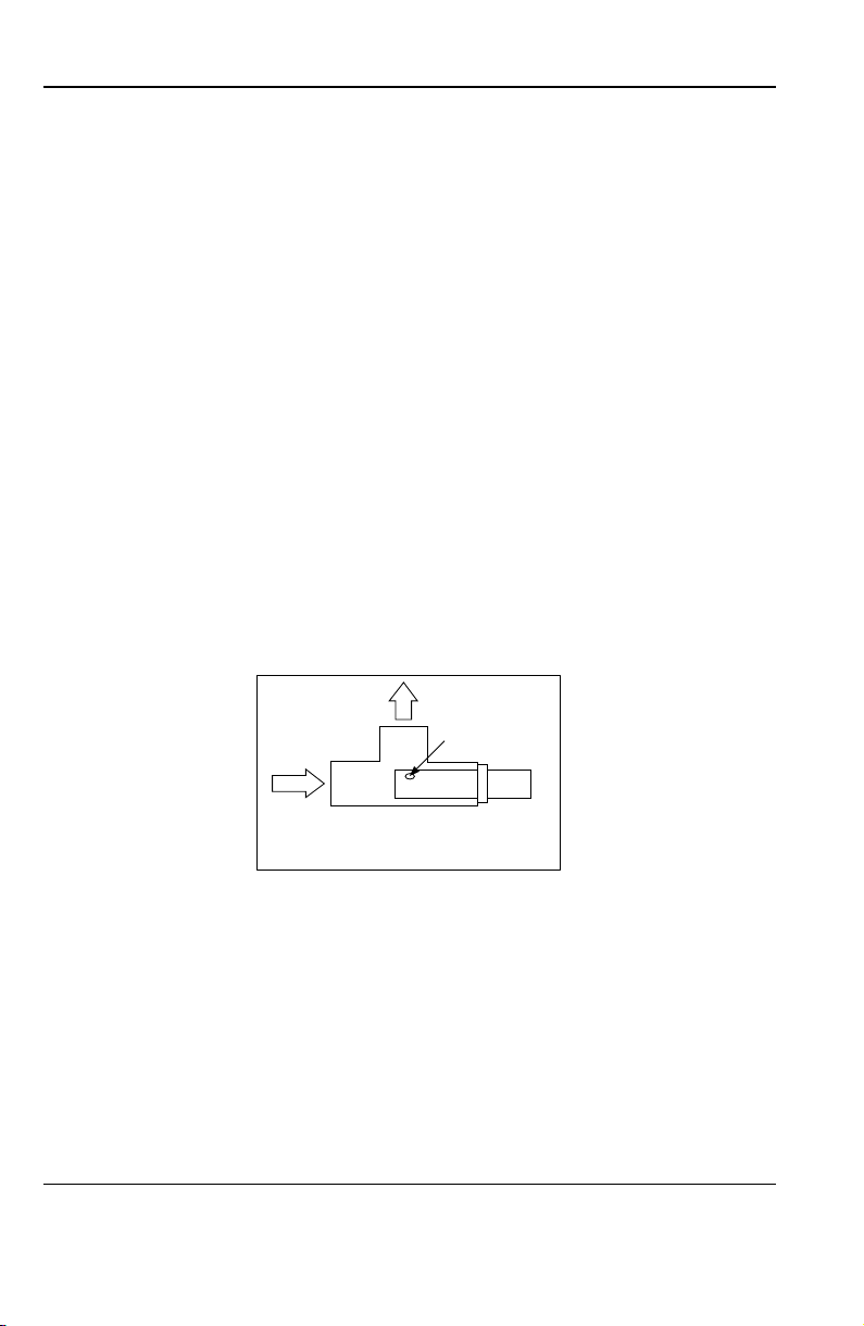
3.1 Installation
The sensors are to be mounted in such a way that the sample medium
flows directly into the sensor through the orifice at the tip and re-emerges
through the vent holes. Any other installation position of the sensors can
create the risk of formation of airlocks, or of contamination through deposits of solid matter.
Flow direction
Flow
direction
Orientation in fluids
with low velocity
Vent hole
Sensor
T-piece
Flow of sample medium must be toward the face of the sensor. Air bubbles
and solid matter deposits are to be avoided. A minimum clearance of 0.6
cm (1/4") between sensor and pipe wall must be maintained at the tip of
the sensor.
Vertical mounting (top entry) in a pipe is recommended only if the pipe is
full and no air bubbles are able to develop in the flow.
In the event of side mounting (side entry) of the sensor, vertical upward
flow of sample process medium must be ensured.
InPro 7000-VP Series © 02 / 2017 Mettler-Toledo GmbH, CH - 8606 Greifensee
52 002 091 Printed in USA
InPro 7000-VP Series 13
3.2 Electrical connections
All of the InPro 7000-VP Series sensors can be connected to the asso ciated
transmitter using the appropriate multiwire cable from METTLER TOLEDO.
Depending on which type of transmitter is employed, not all cable strands
may have to be used.
Colors and function of the cable strands (supplied separately)
Connection to the relative transmitter must be followed according to the
wiring diagram below.
2-electrode sensor Color
Inner electrode white
Outer electrode white / blue
RTD green
RTD sense red
RTD / GND Bare shield
Connection to the relative transmitter must be followed according to the
wiring diagram (see respective transmitter instruction manual for detail).
METTLER TOLEDO supplies the cables. Please refer to chaper 7 “Accesso-
ries” for ordering information
© 02 / 2017 Mettler-Toledo GmbH, CH - 8606 Greifensee InPro 7000-VP Series
Printed in USA 52 002 091
14 InPro 7000-VP Series
4. Maintenance and troubleshooting
4.1 Conditions of warranty
METTLER TOLEDO guarantees the quality of materials and workmanship
within a narrow range of manufacturing tolerances, so that the product
purchased is free from any substantial deviations from material and
manufacturing quality standards. The warranty is valid for a period of
one year from date of delivery: If within this warranty period, any repair or
replacement should become necessary, and such cause is not due to
misuse or incorrect application, please return the sensor, freight pre-paid,
to your appropriate METTLER TOLEDO supplier. Repair work will be carried out free of charge. Final decision on whether the defect is due to a
manufacturing error or to incorrect operation of the sensor by the customer
is made at the option of the Customer Service department of METTLER
TOLEDO. After expiration of the warranty period, sensors will be repaired
or replaced on an exchange basis against payment of the costs involved.
4.2 Maintenance
Dirty or contaminated sensors can deliver incorrect measurement values.
If fouling is presumed, the sensor is to be removed from operation and the
electrodes as well as the insulation between the electrodes cleaned with
a soft cloth. Suitable cleaning solutions are mild detergents or diluted
acids (< 0.5 % by wt.) such as nitric acid. Never use clean ing agents that
are not compatible with the material to be cleaned.
When handling acids, precautionary measures are to be taken.
The sensor must be thoroughly flushed with distilled or deionized water
prior to re-installation.
Following cleaning and re-installation into the process, it can take from
several minutes up to several hours until the sensor delivers the originally
measured value.
InPro 7000-VP Series © 02 / 2017 Mettler-Toledo GmbH, CH - 8606 Greifensee
52 002 091 Printed in USA

InPro 7000-VP Series 15
4.3 Troubleshooting
Error Possible cause Corrective action
No signal on display Electrical connections either missing
or incorrectly in place
Check all connections and
associated cabling
Sensor is not in contact with the
sample medium
No temperature signal Temperature probe is not connected
Transmitter does not support
Pt1000 RTD
Incorrect or unstable
measurement reading
Sensor is contaminated/fouled
Sensor is installed too close to pipe
wall
Check installation for air
pockets
Check all connections and
associated cabling
Replacement of transmitter or
sensor necessary
Clean the sensor
(electrodes)
Ensure minimum distance
of 0.6 cm (1/4") between
sensor tip and pipe wall is
maintained.
© 02 / 2017 Mettler-Toledo GmbH, CH - 8606 Greifensee InPro 7000-VP Series
Printed in USA 52 002 091

16 InPro 7000-VP Series
5 Removal from operation, storage, disposal
5.1 Removal from operation
The sensor is only conditionally subject to aging. When used as intended
and appropriately maintained and serviced, the lifetime of the sensor can
extend to several years.
Before removing the sensor from the process/process adapter, it must be
ensured that the process pressure has been reduced to a safe level and
the process temperature has lowered to a safe range. Any escape of hot
process medium under pressure can cause damage to material/equipment
or injury to persons.
After removal from the process the sensor should first be flushed with
distilled water.
If the sensor incurs a defect, it can not be repaired and must be disposed
under observance of prevailing local regulations.
5.2 Storage
If the sensor is not use, it can be stored dry. However, it has to be recon-
ditioned in the process fluid accordingly prior to renewed operat ion. This
procedure may take several hours to complete.
5.3 Disposal
The user is responsible for the proper disposal of the conductivity sensor. The
sensor contains electronic components that must be disposed of correctly
in order to avoid hazards to people or to the environment.
InPro 7000-VP Series © 02 / 2017 Mettler-Toledo GmbH, CH - 8606 Greifensee
52 002 091 Printed in USA
 Loading...