

Mettler Toledo InPro 6800 Instruction Manual
InPro 6800 Series O2Sensors
Instruction manual
Bedienungsanleitung
Instructions d’utilisation
InPro 6800
52 200 953

2 InPro 6800 Series O2Sensor 12/25 mm
InPro 6800 © 02 / 17 Mettler-Toledo GmbH
52 200 953 Printed in Switzerland
English Page 3
Deutsch Seite 36
Français Page 69
InDip, InFit, InPro, ISM, and InTrac are registered trademarks
of the Mettler Toledo Group in Switzerland and a further twelve countries.

InPro 6800 Series O2Sensor 12/25 mm 3
© 02 / 17 Mettler-Toledo GmbH InPro 6800
Printed in Switzerland 52 200 953
InPro 6800 Series O2Sensors
Instruction manual

4 InPro 6800 Series O2Sensor 12/25 mm
InPro 6800 © 02 / 17 Mettler-Toledo GmbH
52 200 953 Printed in Switzerland
1 Introduction................................................................5
2 Important notes ..........................................................6
2.1 Notes on operating instructions .....................................6
2.2 Intended use ...............................................................6
2.3 Safety instructions........................................................7
2.4 Examples of some typical applications...........................8
2.5 Use in Ex-zones...........................................................8
2.6 Ex-classification ATEX ..................................................9
2.6.1 Introduction.................................................................9
2.6.2 Rated data..................................................................9
2.6.3 Special conditions......................................................10
2.7 Ex-classification FM approved.....................................11
3.1 General information....................................................12
3.2 Principle...................................................................12
3.3 Scope of delivery .......................................................12
3.4 Equipment features ....................................................13
4 Installation...............................................................15
4.1 Mounting the sensor...................................................15
4.2 Connection................................................................15
4.2.1 Connecting the InPro 6800 to a cable..........................15
4.2.2 Connecting the VP or AK9 cable to the transmitter..........16
5 Operation .................................................................17
5.1 Start-up and polarizing...............................................17
5.2 Calibration................................................................18
5.2.1 Purpose of calibration ................................................18
5.2.2 What you have to know for calibration .........................18
5.2.3 Single point calibration...............................................19
5.2.4 Dual point calibration.................................................20
6 Maintenance ............................................................21
6.1 Inspection of the sensor..............................................21
6.1.1 Visual inspection .......................................................21
6.1.2 Testing the sensor with the METTLER TOLEDO O
2
Sensor-Master InPro 6800..........................................22
6.1.3 Testing the sensor via a transmitter..............................23
6.2 Changing the electrolyte, the membrane body or
the interior body.........................................................24
7 Storage ....................................................................27
8 Product specification ................................................27
8.1 Certificates................................................................27
8.2 Specifications............................................................28
9 Ordering information.................................................29
9.1 Sensors....................................................................29
9.2 Accessories...............................................................29
9.3 Spare parts ...............................................................30
9.4 Recommended transmitters.........................................30
9.5 Recommended housings............................................30
10 Theory of the polarographic sensor............................31
10.1 Introduction...............................................................31
10.2 Principle of the design of an oxygen electrode...............32
10.3 Parameters determining current...................................32
10.4 Polarization voltage ...................................................33
10.5 Temperature..............................................................33
10.6 Dependence on flow...................................................34
10.7 Oxygen partial pressure – oxygen concentration............35
Contents

InPro 6800 Series O2Sensor 12/25 mm 5
© 02 / 17 Mettler-Toledo GmbH InPro 6800
Printed in Switzerland 52 200 953
1 Introduction
Thank you for buying the InPro®6800 sensor from
METTLER TOLEDO.
The construction of the InPro 6800 sensors employs
leading edge tech nology and complies with safety
regulations currently in force. Notwithstanding this,
improper use could lead to hazards for the user or a
third-party, and/or adverse effects on the plant or
other equipment. Therefore, the operating instruc-
tions must be read and understood by the persons
involv ed before work is started with the sensor.
The instruction manual must always be stored close at
hand, in a place accessible to all people working with
the InPro 6800.
If you have questions, which are not or insufficiently
answered in this instruction manual, please contact
your METTLER TOLEDO supplier. They will be glad to
assist you.

6 InPro 6800 Series O2Sensor 12/25 mm
InPro 6800 © 02 / 17 Mettler-Toledo GmbH
52 200 953 Printed in Switzerland
2 Important notes
2.1 Notes on operating instructions
These operating instructions contain all the information
needed for safe and proper use of the InPro 6800
sensor.
The operating instructions are intended for personnel
entrusted with the operation and maintenance of the
sensors. It is assumed that these persons are familiar
with the equipment in which the sensor is installed.
Warning notices and symbols
This instruction manual identifies safety instructions
and additional information by means of the following
symbols:
This symbol draws attention to safety instructions and
warnings of potential danger which, if neglected,
could result in injury to persons and/or damage to
property.
This symbol identifies additional information and
instruc tions which, if neglected, could lead to defects,
inefficient operation and possible loss of production.
2.2 Intended use
METTLER TOLEDO InPro 6800 sensors are intended
solely for inline measurement of the oxygen partial
pressure in liquids and gases, as described in this instruction manual.
Any use of these sensors which differs from or exceeds
the scope of use described in this instruction manual
will be regarded as inappropriate and incompatible
with the intended purpose.
The manufacturer/supplier accepts no responsibility
whatsoever for any damage resulting from such
improper use. The risk is borne entirely by the user/
operator.
Other prerequisites for appropriate use include:
– compliance with the instructions, notes and
requirements set out in this instruction manual.
– acceptance of responsibility for regular inspection,
maintenance and functional testing of all asso ci ated components, also including compliance
with local operational and plant safety regulations.
– compliance with all information and warnings
given in the documentation relating to the products
used in conjunction with the sensor (housings,
transmitters, etc.).
– observance of all safety regulations governing the
equipment in which the sensor is installed.

InPro 6800 Series O2Sensor 12/25 mm 7
© 02 / 17 Mettler-Toledo GmbH InPro 6800
Printed in Switzerland 52 200 953
– correct equipment operation in conformance with
the prescribed environmental and operational
conditions, and admissible installation positions.
– consultation with METTLER TOLEDO Process
Analytics in the event of any uncertainties.
2.3 Safety instructions
– The plant operator must be fully aware of the
potential risks and hazards attached to operation
of the particular process or plant. The operator is
responsible for correct training of the workforce, for
signs and markings indicating sources of possible
danger, and for the selection of appropriate,
state-of-the-art instrumentation.
– It is essential that personnel involved in the
commissioning, operation or maintenance of these
sensors or of any of the associated equipment (e.g.
housings, transmitters, etc.) be properly trained in
the process itself, as well as in the use and
handling of the associated equipment. This
includes having read and understood this instruction manual.
– The safety of personnel as well as of the plant itself
is ultimately the responsibility of the plant operator.
This applies in particular in the case of plants
operating in hazardous zones.
– The oxygen sensors and associated components
have no effect on the process itself and cannot
influence it in the sense of any form of control
system.
– Maintenance and service intervals and schedules
depend on the application conditions, composition
of the sample media, plant equipment and signi ficance of the safety control features of the
measuring system. Processes vary considerably,
so that schedules, where such are specified, can
only be regarded as tentative and must in any case
be individually established and verified by the plant
operator.
– Where specific safeguards such as locks, labels,
or redundant measuring systems are necessary,
these must be provided by the plant operator.
– A defective sensor must neither be installed nor put
into service.
– Only maintenance work described in this operating
instruction may be performed on the sensors.
– When changing faulty components, use only
original spare parts obtainable from your METTLER
TOLEDO supplier (see spare parts list, ”Section
9.3”).

8 InPro 6800 Series O2Sensor 12/25 mm
InPro 6800 © 02 / 17 Mettler-Toledo GmbH
52 200 953 Printed in Switzerland
– No modifications to the sensors and the acces-
sories are allowed. The manufacturer accepts no
responsibility for damages caused by unauthorised
modifications. The risk is borne entirely by the user.
2.4 Examples of some typical applications
Below is a list of examples of typical fields of application for the oxygen sensors. This list is not exhaustive.
Measurement in liquids:
– Fermentation
– Yeast propagation
– Wort aeration
– Spring water conditioning
– Storage ans processing of fruit juices
Measurement in gases:
– Monitoring of the oxygen limit value to protect
products from oxidation.
– Monitoring of the oxygen limit value in the exhaust
air of fermentation vessels.
– Monitoring of oxygen limit values during inertiza-
tion processes.
– Measurement of oxygen concentrations in process
gas mixtures.
2.5 Use in Ex-zones
Attention!
For an installation in Ex-zones please read the
guidelines following hereafter:
1258
Ex-classification ATEX:
Ex ia IIC T6/T5/T4/T3 Ga/Gb
Ex ia IIIC T69°C/T81°C/T109°C/T161°C Da/Db
Number of the test certificate:
SEV 14 ATEX 0169 X
IECEx SEV 14.0026X
Ex-classification FM approved:
IS / I, II, III /1/ABCDEFG / T6 Ta = 60 °C
- 53 800 002; Entity

InPro 6800 Series O2Sensor 12/25 mm 9
© 02 / 17 Mettler-Toledo GmbH InPro 6800
Printed in Switzerland 52 200 953
2.6 Ex-classification ATEX
2.6.1 Introduction
According to Directive 94/9/EC (ATEX 95) Appendix I,
the O
2
oxygen sensors type InPro 6XXX is a devices
of equipment group II, category 1/2G which, according to Directive 99/92/EC (ATEX 137) can be used in
zones 0/1 or 1/2 or 1 or 2 as well as gas groups IIA,
IIB and IIC, which are potentially explosive due to
combustible substances in the temperature T3 to T6.
The requirements specified in EN 60079-14 must be
observed during use / installation.
According to Directive 94/9/EC (ATEX 95) Appendix
I, the O
2
oxygen sensors type InPro 6XXX is a devices of equipment group II, category 1/2D which,
according to Directive 99/92/EC (ATEX 137) can be
used in zones 20/21 or 21/22 or 21 or 22, which
are potentially explosive due to combustible dust.
The requirements specified in EN 60079-14 must be
observed during use / installation.
For the analog version of the O
2
oxygen electrode,
the O2measurement circuit, temperature measurement circuit and data chip circuit are part of the common intrinsically safe system and are jointly connected to and operated by a separately certified
transmitter.
The digital version of the O
2
oxygen sensor is connected to and operated by two-wire cable to the certified transmitter.
The intrinsically safe circuits are galvanically isolated
from the non-intrinsically safe circuits up to a nominal voltage peak value of 375 V and from the earthed
parts up to a nominal voltage peak value of 30 V.
2.6.2 Rated data
Analog O
2
Oxygen sensor
With type of protection: intrinsic safety to Ex ia IIC
O
2
measuring circuit, temperature measuring
circuit and data chip circuit
Only for connection to certified intrinsically safe circuits. Maximum values:
Ui≤ 16 V, Ii≤ 190 mA, Pi≤ 200 mW
Li= 0 (effective internal inductance)
Ci= 900 pF (effective internal capacitance)
The values above apply, each as the sum of all the
individual circuits of the associated intrinsically safe
supply and evaluation unit (transmitter).
Digital O
2
Oxygen sensor
With type of protection: intrinsic safety to Ex ia IIC

10 InPro 6800 Series O2Sensor 12/25 mm
InPro 6800 © 02 / 17 Mettler-Toledo GmbH
52 200 953 Printed in Switzerland
Two-wire current circuit
Only for connection to certified intrinsically safe circuits. Maximum values:
Ui≤ 16 V, Ii≤ 30 mA, Pi≤ 50 mW
Li= negligible
Ci= negligible
2.6.3 Special conditions
– The relationship between the maximum permissi-
ble ambient or media temperature and temperature class, for category 1G applications, zone 0, is
shown in the following table:
Temperature class Max. ambient or
media temperature
T 6 68 °C
T 5 80 °C
T 4 108 °C
T 3 160 °C
– The relationship between the maximum permissi-
ble ambient or media temperature and temperature class, for category 1D applications, zone 20,
is shown in the following table:
Temperature class Max. ambient or
media temperature
T 69 °C 68 °C
T 81 °C 80 °C
T 109 °C 108 °C
T 161 °C 160 °C
– The capacitance and inductance of the connecting
cable has to be considered.
– The O
2
Oxygen sensor type InPro 6XXX can be
used in / with the fittings InFit®76*-*** or InTrac
®
7**-***, or in / with other suitable fittings in potentially explosive areas.
– The metal body of the O
2
Oxygen sensors, or the
fittings InFit 76*-*** or InTrac 7**-***, or other
appropriate fitting is optionally included in the routine pressure test of the system.
– The independent fitting used for installation of O
2
Oxygen sensor must be conductively connected to
the equipotential bonding system.
InPro 6800 Series O2Sensor 12/25 mm 11
© 02 / 17 Mettler-Toledo GmbH InPro 6800
Printed in Switzerland 52 200 953
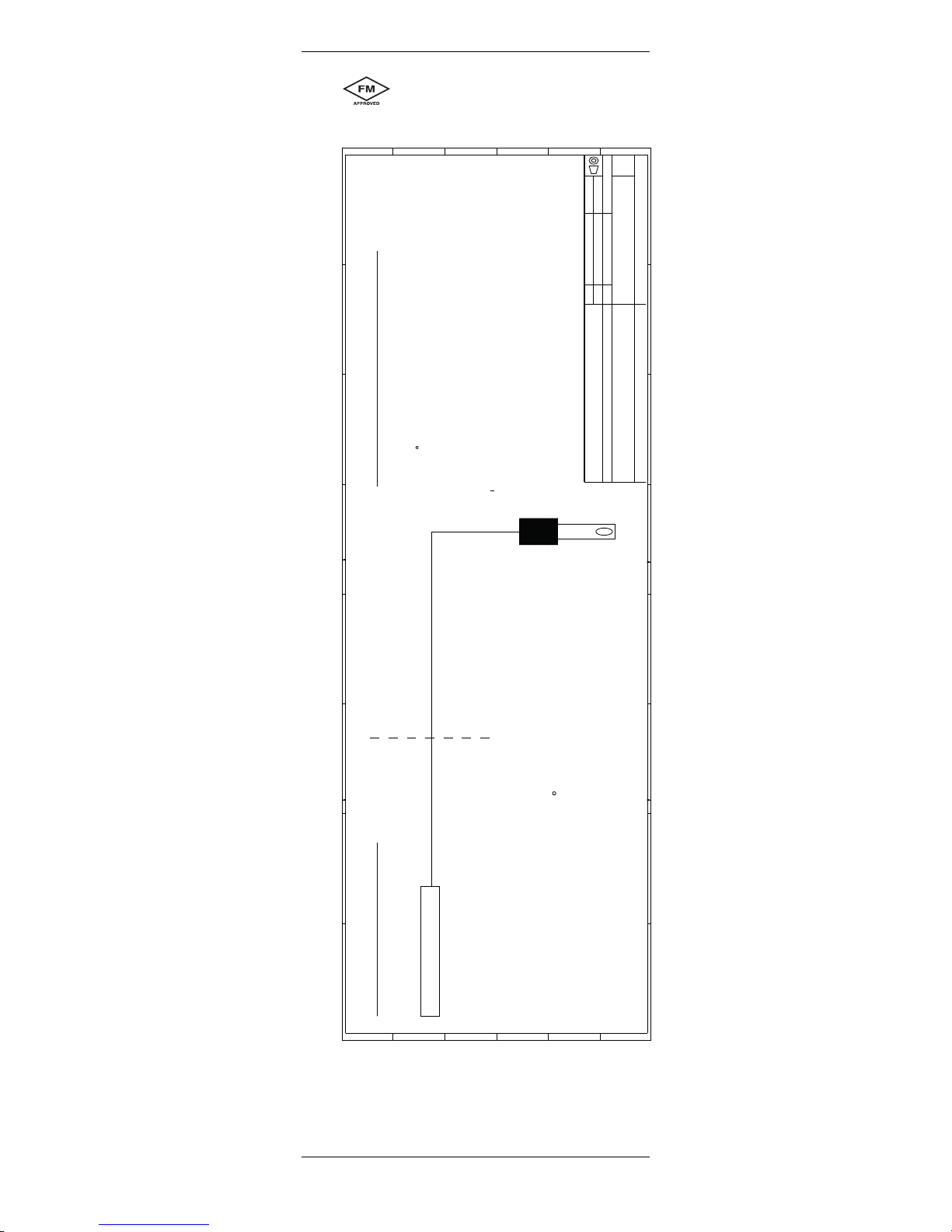
2.7 Ex-classification FM approved
A
B
C
D
E
F
F
E
D
C
B
A
1 2 3 4 5 6 7 8
1 2 3 4 5 6 7 8
Index
Title
Drawing No
METTLER TOLEDO
Process Analytics
CH-8902 Urdorf
Drawn F.Kogelmann 11-Dez-03 Scale 1:1
Change Dario Meier 25-Mai-16 Format DIN A3
Schutzvermerk ISO 16016 beachten / Refer to protection notice ISO 16016
Note - Replaces -
FM control drawing
53800002
E.4
Model: MODEL NAME
E.4
ArtikelNr: 53800002
Drawing: E.4 Rel.Level: Released Sheet: 1
/
1
R
Notes:
1. No revision to this drawing is permitted without FMRC approval.
2. Vmax > Vt; Imax > It; (Ci of all loops + C cable) < Ca; (Li of all loops + L cable) < La
Pmax or Pi > Po
3. Single Multi-Channel IS Barrier or Apparatus must be FMRC Approved.
4. Single Multi-Channel IS Barrier or Apparatus manufacturer`s control drawings
must be followed when installing the System. IS Barrier or Equipment may be
installed within the Hazardous (Classified) location for which it is approved.
5. Installation must be in accordance with Article 500 of the NEC (ANSI/NFPA 70) and
ANSI/ISA RP12.6.
WARNING: substitution of components may inpair intrinsic safety.
Entity Parameters:
Vmax (Ui)=16V, Imax (Ii)=50mA, Pi=0.25W
Ci=0.1 uF, Li=0 mH
Probe
Class I, Division 1, Groups A, B, C and D
Class II, Division 1, Groups E, F, and G
Class III, Division 1
T6 Ta=60 C
HAZARDOUS (CLASSIFIED) LOCATION
Any FMRC Approved Single
Multi-Channel Barrier or Apparatus
NONHAZARDOUS LOCATION

12 InPro 6800 Series O2Sensor 12/25 mm
InPro 6800 © 02 / 17 Mettler-Toledo GmbH
52 200 953 Printed in Switzerland
3 Product description
3.1 General information
The sensor InPro 6800 with integrated temperature
probe is used for oxygen meas ure ment.
The sensor is sterilizable and autoclavable and
compatible with CIP (cleaning in place).
InPro 6800 sensors with ISM®functionality offer Plug
and Measure as well as enhanced diagnostics
features.
ISM sensors are available with K8S (fully digital) or VP
connector.
3.2 Principle
Here is a short summary of the principle of pola rographic measurement on which this sensor is based
(Clark 1961).
a) The Clark polarographic sensor basically consist
of a working electrode (cathode), a counter/reference electrode (anode), and an oxygen permeable
mem brane which separates the electrodes from the
sample medium.
b) The transmitter supplies a constant polarization
voltage to the cathode, needed to reduce oxygen.
c) The oxygen molecules which migrate through the
permeable membrane are reduced at the cathode.
At the same time, oxidation takes place at the
anode and oxidized anode metal (silver) is libe rated as silver ions into the electrolyte. The electro lyte closes the electric circuit between anode and
cathode (ion conductivity).
d) The current produced by the reactions described
above is measured by the transmitter and is
proportional to the partial pressure of oxygen
(pO
2
) in the sample medium.
Please refer to Section 10 ”Theory of the polarogra phic
sensor” for further information.
3.3 Scope of delivery
Each sensor is supplied fully assembled and factorytested for correct function together with:
– a quality control certificate
– inspection certificates 3.1B
(complying with EN 10204.3/1B)
See electrolyte order details at section „Spare Parts“,
9.3.
InPro 6800 Series O2Sensor 12/25 mm 13
© 02 / 17 Mettler-Toledo GmbH InPro 6800
Printed in Switzerland 52 200 953
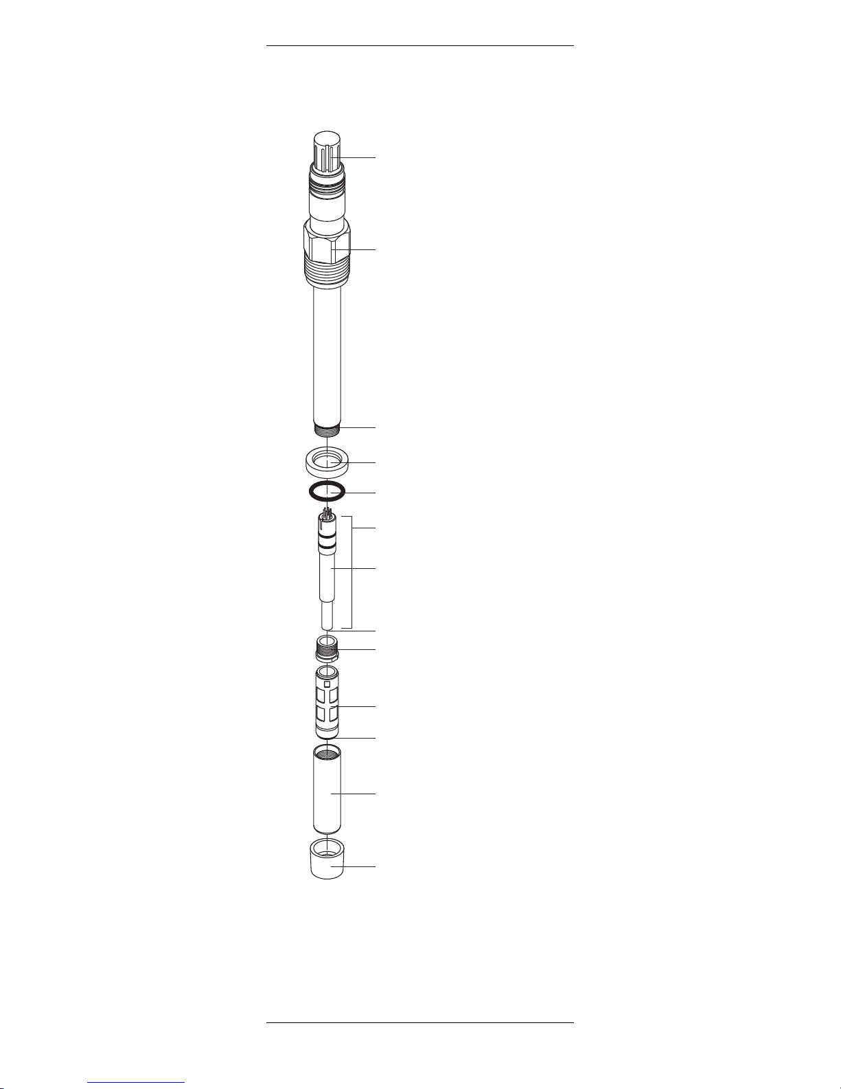
3.4 Equipment features
12 mm Sensor
VP connector
(straight version)
(K8S connector for digital ISM)
O-ring
(10.77x2.62 mm, Silicone FDA)
Interior body
Anode
(solid silver)
Cathode
Retainer nut
O-ring
(Silicone FDA/USP VI)
Cap sleeve (N-type)
Protection cap
Washer
Pg 13.5 threaded sleeve
O-ring
(9.0x1.0 mm, Silicone FDA/USP VI)
Membrane body
14 InPro 6800 Series O2Sensor 12/25 mm
InPro 6800 © 02 / 17 Mettler-Toledo GmbH
52 200 953 Printed in Switzerland
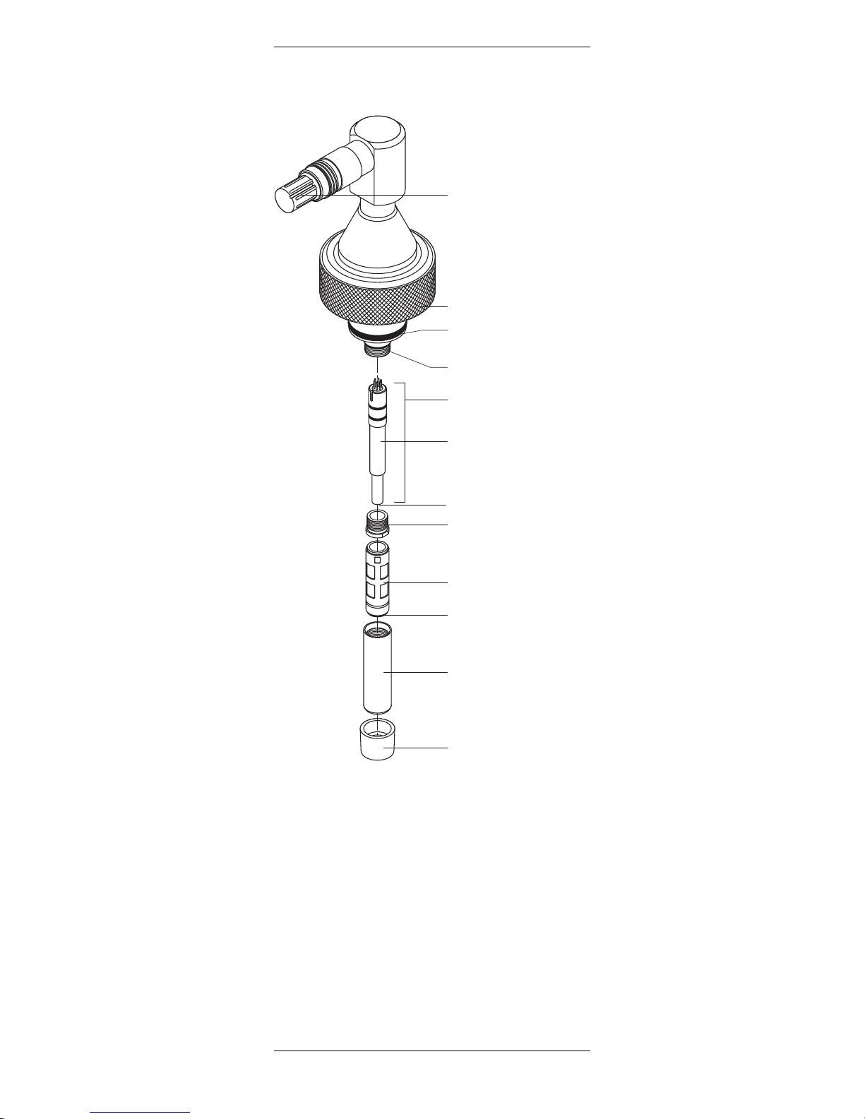
Cap nut G1"
O-ring
(20.29 x2.62 mm, Silicone FDA/
USP VI)
Interior body
Anode
(solid silver)
Cathode
Retainer nut
Membrane body
Cap sleeve (N-type)
Protection cap
25 mm Sensor
O-ring
(9.0x1.0 mm, Silicone FDA/
USP VI)
O-ring
(Silicone FDA/USP VI)
VP connector
(angled version)
(K8S connector for digital
ISM)
InPro 6800 Series O2Sensor 12/25 mm 15
© 02 / 17 Mettler-Toledo GmbH InPro 6800
Printed in Switzerland 52 200 953
4 Installation
4.1 Mounting the sensor
Important! Remove the green protective cap before
mount ing the sensor.
Mounting the sensor in a housing
Please refer to the instruction manual of your housing
explaining on how to mount the sensor in place.
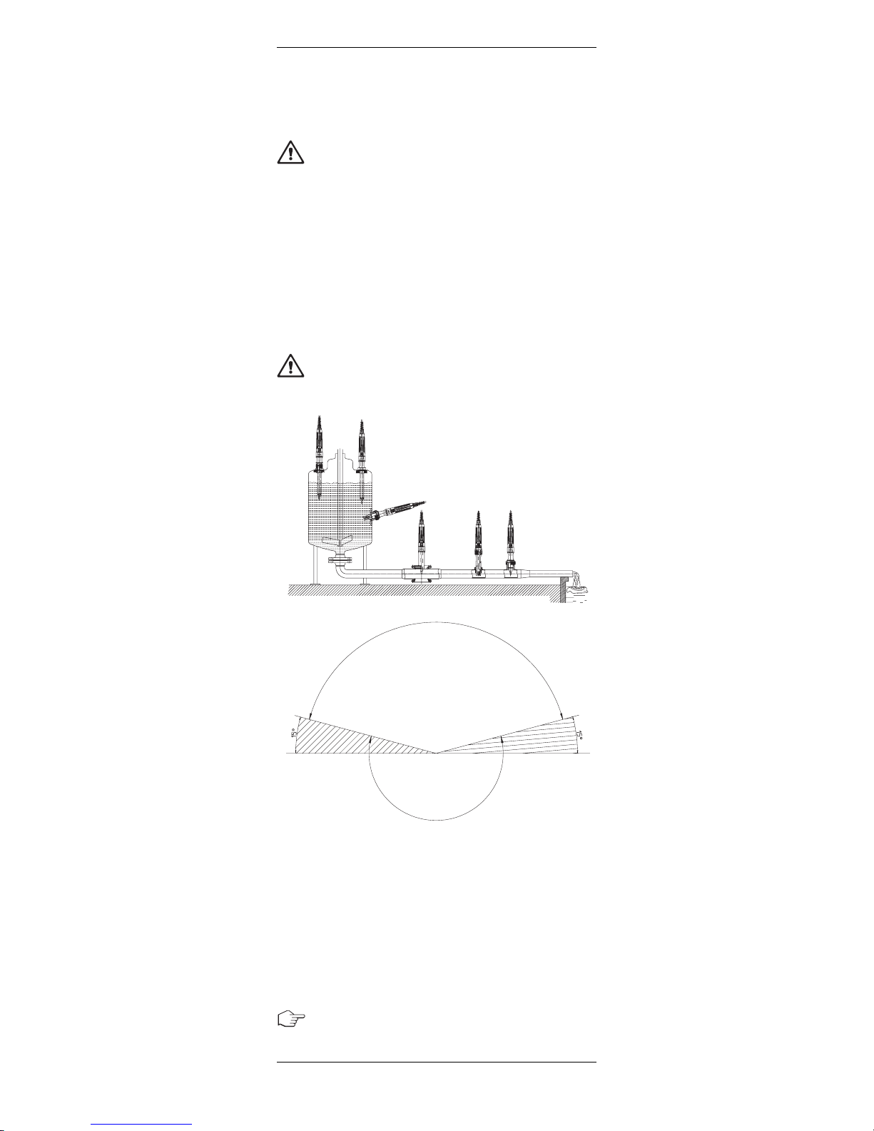
Mounting the sensor directly on a pipe or a vessel
The sensor can be mounted vertically or in an inclined
position. In the case of inclined mounting, the angle of
the housing must be equal to or greater than 15° above
the horizontal.
Caution! Installation outside the admissible range of
mounting positions is not allowed, otherwise correct
operation of the sensors / electrodes may be impaired.
52910536
admissible mounting positions
zulässige Einbaulagen
positionements de montage admis
admissible mounting position
zulässige Einbaulage
positionement de montage admis
inadmissible (except for optical sensors)
unzulässig (ausser für optische Sensoren)
ne pas admissible (sauf pour sondes optiques)
The 12 mm sensors can be mounted directly through
a socket with inside thread Pg 13.5 and securely tightened via the Pg 13.5 threaded sleeve.
The 25 mm sensors can be mounted directly through
a standard weld-in socket or the safety weld-in sockket
from METTLER TOLEDO.
4.2 Connection
4.2.1 Connecting the InPro 6800 to a cable
Sensors with ISM functionality require the use of a special AK9 cable as well as an ISM compatible O
2
trans-

16 InPro 6800 Series O2Sensor 12/25 mm
InPro 6800 © 02 / 17 Mettler-Toledo GmbH
52 200 953 Printed in Switzerland
4.2.2 Connecting the VP or AK9 cable to the transmitter
Note: Cable assignment can be found in the METTLER
TOLEDO VP or AK9 cable instruction manual.
Note: For connecting the cable to the terminals of the
transmitter, please refer to the instructions given in the
METTLER TOLEDO transmitter manual.
VP or AK9 cable
O
2
transmitter
VP-6 cable for standard use
AK9 cable for ISM functionality
Plug
Pin
Slit
VP connector
K8S connector for
digital ISM
mitter. The sensor is connected to the transmitter via a
AK9 cable. The AK9 cable ensures a secure connection
between the transmitter and the sensor under harsh
industrial conditions. The robust watertight IP68 connector housing guarantees maximum process safety.
If you have chosen to use a sensor with digital ISM
functionality, the K8S connector will incorporate a preamplifier. It is absolutely necessary to protect this electronic component against any electrical charge.
Do not touch the sensor at the VP connector plug.
To connect the VP cable to the sensor align the slit of
the VP connector with the pin in the plug. Then tightly
screw the plug to fasten the two parts.
InPro 6800 Series O2Sensor 12/25 mm 17
© 02 / 17 Mettler-Toledo GmbH InPro 6800
Printed in Switzerland 52 200 953
5 Operation
Attention! Before using the sensors for the first time,
the electrolyte should be replaced (see ”Chapter 6.2”).
Due to possible adverse conditions during transport
and storage (e.g. airfreight; pressure and temperature
variations), the quality of the electrolyte may become
impaired. Poor electrolyte quality can lead to erroneous
measurement values.
5.1 Start-up and polarizing
Attention! The protective cap at the tip of the sensor
must be removed before putting the sensor into
ope ration.
When the system is operated for the first time or if the
sensor has been disconnected from the voltage source
(transmitter or O
2
Sensor-Master) for longer than
5 min utes, the sensor has to be polarized prior to
calibration by connecting it to the operating O2transmitter or to a sensor master. After 6 hours, the sensor
is fully polarized and ready for operation.
A shorter polarization period is sufficient if the sensor
has been disconnected for only a few minutes. The
following table serves to establish the correct polari zation time in relation to the depolarization time.
Depolarization time1 Minimum required
t
depol
[Min.] polarization time2[Min.]
t
depol
> 30 360
30 > t
depol
> 15 6 * t
depol
15 > t
depol
> 5 4 * t
depol
t
depol
< 5 2 * t
depol
1 Depolarization time:
Time span in which the polarization voltage is cut off
from the sensor. This is the case during:
– change of electrolyte
– change of membrane body
– the time the cable is disconnected or no transmitter
or sensor master is connected to the cable
2 Polarization time:
Time span during which the sensor is under a polari zation voltage.
Attention! Setting of the polarization voltage on the
transmitter for correct measurements:
– Standard applications (e.g. measurement in
bio tech nology): – 675 mV
– Measurement of permanently low oxygen concen-
trations <500 ppb in the presence of volatile
acidic components (e.g. carbon dioxide during
measurements in breweries): – 500 mV
Important! To ensure the supply of the correct polariza tion voltage the transmitter must be set accordingly.
18 InPro 6800 Series O2Sensor 12/25 mm
InPro 6800 © 02 / 17 Mettler-Toledo GmbH
52 200 953 Printed in Switzerland
5.2 Calibration
5.2.1 Purpose of calibration
Each oxygen sensor has its own individual slope and
own individual zero point. Both values are subject to
change, for example, through electrolyte consumption
or after exchange of electrolyte or membrane body. To
ensure high measurement accuracy of the sensor, a
calibration must be carried out after each change of
electrolyte or membrane. Prior to calibration, the
sensor has to be polarized for at least 6 hours.
A zero point calibration is only advisable if very high
accuracy is required at low oxygen concentrations.
To check if your sensor needs a recalibration, you
may dry it and take it in the air to check that the
reading is close to 100%. If not, then the sensor
needs a new calibration.
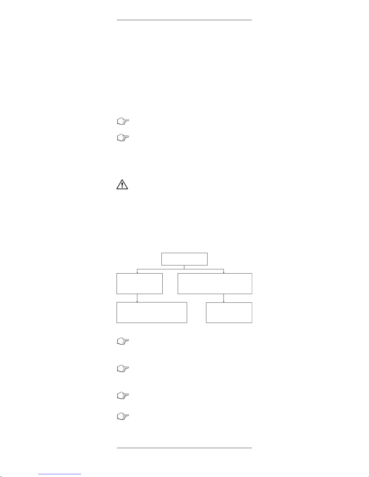
5.2.2 What you have to know for calibration
Attention! If dissolved oxygen is being measured at
low concentrations (<500 ppb) in the presence of
volatile acidic components (e.g. carbon dioxide (CO
2
)
measurements in breweries), the calibration procedure
described below should be followed in order to achieve
the best measurement performance.
No special calibration procedure is required if dissolved
oxygen is being measured in standard applications
(e.g. measurement in biotechnology).
First step: Adjust the transmitter polarization voltage
to – 675 mV. Detailed information is given in the transmitter instruction manual.
Second step: After adjusting the polarization voltage
to – 675 mV, equilibration time is required. Wait for
about 5 minutes before carrying out step 3.
Third step: Perform calibration according to the transmitter’s instruction manual.
Fourth step: Adjust the transmitter polarization voltage
back to –500 mV.
Where is oxygen
being measured?
Standard applications
(e.g. measurement in
biotechnology).
No special procedure required.
Refer to transmitter instruction
manual and general remarks below.
Follow step 1 to step 4
and general remarks
below.
Measurement of permanently low oxygen
concentrations (<500ppb) in the pre-
sence of volatile acidic components
(e.g. CO
2
at measurements in breweries).

InPro 6800 Series O2Sensor 12/25 mm 19
© 02 / 17 Mettler-Toledo GmbH InPro 6800
Printed in Switzerland 52 200 953
General remarks:
– For calibration in air, the sensor membrane must
be dry, since adhering water drops can falsify the
measured oxygen value.
– Make sure that the oxygen saturation index of the
calibration medium is correct and remains
constant during calibration.
– In the event of calibration in water or sample
medium, the calibration medium must be in
equilibrium with the air. Oxygen exchange
between water and air is only very slow. Therefore
it takes quite long time until water is saturated with
atmospheric oxygen.
– For correct calibration, a minimum flow rate of the
calibration medium is necessary.
– Calibration in a fermenter should be performed
after sterilization (as sterilization may alter the
sensor slope), but prior to innoculation. If it is not
possible to perform the calibration after sterilization,
the use of an existing membrane body that has
been pre-sterilized while mounted in the sensor is
recommended. A slope alteration of some per cent
can occur with new membrane bodies, particularly
after a first sterilization, as the tension of the membrane may be altered by the sterilization process.
– Make sure that all other parameters, such as
temperature and pressure, are constant.
For continuous applications, we recommend periodic
recalibration in line with your requirements on
accuracy, the type of process in operation and your
own experience. The frequency of the need for re-
calibration depends very much on the specific
application, and therefore appropriate intervals cannot
be exactly defined here.
5.2.3 Single point calibration
By carrying out a single point calibration, the factual
slope of the sensor can be established. The calibration
medium can be water with known oxygen saturation
index (e.g. air-saturated water) or air with known
water-vapor saturation (e.g. water-vapor saturated
air).
After the sensor signal has stabilized, the complete
meas uring system can then be calibrated to the 100 %
value of the desired measurable variable, e.g.100 %
Steps 1 to 4 can be accomplished automatically if you
use the M 700 transmitter. Thus the routine can be
minimized to a few keystrokes. In addition the M 700
transmitter must be equipped with the software function
SW-700-011 ”high CO
2
compensation”. Please ask
your local METTLER TOLEDO distributor.

20 InPro 6800 Series O2Sensor 12/25 mm
InPro 6800 © 02 / 17 Mettler-Toledo GmbH
52 200 953 Printed in Switzerland
air, 20.95 % O2, or 8.26 ppm at 25 °C (77 °F) and
normal pressure (see instruction manual for the trans mitter).
Single point calibration should be sufficient for almost
all process applications.
5.2.4 Dual point calibration
By carrying out a dual point calibration both slope and
zero point of the sensor can be established.
Important! In case of a dual point calibration, always
start by the zero point calibration before calibrating
the slope.
Due to the very low zero current of METTLER TOLEDO
sensors, dual point calibration is normally not necessary for standard applications.
As a rule, the zero point should be adjusted to zero
manually, or it is automatically performed by the
transmitter (see instruction manual for the transmitter).
A zero point calibration is only advisable if very high
accuracy is required at low oxygen concentrations.
Attention! Incorrect zero point calibration is a
frequent source of measurement error. For correct
calibration, we recommend the use of nitrogen gas
or other oxygen-free medium with a level of purity
of at least 99.995%.
After the sensor signal has stabilized (after 20…30
minutes), the sensor can be calibrated through the
relevant transmitter to the 100 % value of the desired
measurable variable, e.g. 0 % air, 0.0 % O
2
, or
0.0 ppm (see instruction manual for the transmitter).

InPro 6800 Series O2Sensor 12/25 mm 21
© 02 / 17 Mettler-Toledo GmbH InPro 6800
Printed in Switzerland 52 200 953
6 Maintenance
6.1 Inspection of the sensor
6.1.1 Visual inspection
To check your sensor, we recommend the following
procedure:
• The contacts of the connector must be dry.
Moisture, corrosion and dirt in the connector can
lead to false readings.
• Check the cable for buckling, brittle areas or
ruptures.
• Before calibration always examine the membrane
foil optically for signs of damage. The foil must be
intact and clean. Dirty membranes should be
wip ed clean using a soft, moist tissue.
Note: An undulated membrane has no influence on
the sensor performance, assuming the membrane
is intact.
• The membrane body must be replaced if the sensor
has too long a response time, the reading is
unstable or subject to drift, and if the sensor cannot
be calibrated or the membrane shows sign of
mechanical damage.
• Check the cathode area for discoloration, conta -
mination or cracks in the glass. If necessary rinse
with demineralized water and clean with a clean
soft brush or soft paper tissue.
Attention! Do not use any cleaning agents con taining
alcohol. This could damage the sensor or lead to
fault current.
Attention! The glass body is fragile and sensitive to
vibration.
22 InPro 6800 Series O2Sensor 12/25 mm
InPro 6800 © 02 / 17 Mettler-Toledo GmbH
52 200 953 Printed in Switzerland
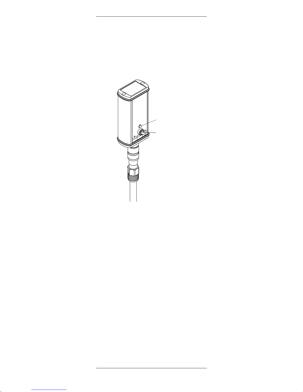
6.1.2 Testing the sensor with the METTLER TOLEDO
O2Sensor-Master InPro 6800
We recommend to use the METTLER TOLEDO O
2
Sensor-Master InPro 6800 to check the quality of your
sensor as follows (not applicable for digital ISM sensors):
• Connect the sensor to the O2Sensor-Master.
LED
Switch
As soon as the sensor is connected to the O
2
Sensor-Master, the polarization function is automatically activated. Please note: if the sensor was
disconnected from the transmitter for longer than
5 minutes, the sensor must be polarized first
(polarizing time see section 5.1) to get representative test results.
• Battery Check:
Push the switch to the left. If the battery is ok and
the O
2
Sensor-Master is operational the green LED
lights up. Otherwise, please consult the instruction
manual of the O2Sensor-Master.
• Sensor Check:
For this test the O2sensor must be fully polarized
and the membrane of the sensor must be dry and
clean.
Expose the sensor (connected to O
2
Sensor Master) to the air. By pushing the switch to the right
to the position ”2 – Sensor check”, the O2SensorMaster checks wether the electrode current for air
measurement delivered by the sensor is within the
admissible range (40 to 100 nA for InPro 6800).
If the green LED lights up the current for air
measurement is with in the admissible range.
METTLER TOLEDO
O
2
Sensor-Master
InPro 6800
Order No. 52 200 892
The polarization function
will be activated automatically
,
when a sensor is connected.
After the sensor polarization
you should check the functions
of the sensor as following:
1. Battery Check
2. Sensor Check
Green light = ok
left
Battery
Check
middle
Autom.
Polariz.
right
Sensor
Check
1
2

InPro 6800 Series O2Sensor 12/25 mm 23
© 02 / 17 Mettler-Toledo GmbH InPro 6800
Printed in Switzerland 52 200 953
If the LED does not light up, you should check the
battery of the O2Sensor-Master (see instruction
manual ”Accessories”). If the battery is working,
than there is probably a problem with your sensor.
You should change the electrolyte and/or the
membrane body of your sensor. If after a
membrane change the LED still does not light up,
this means that there is maybe something wrong
with the interior body of the sensor. You should
than change it (see ”Section 6.2”).
Important! The sensor check function only veryfies
the correctness of the electrode current for air
measurement. In order to be absolutely sure of the
functionality of the sensor, the residual signal in an
oxygen free medium should also be controlled (see
”Section 6.1.3”).
6.1.3 Testing the sensor via a transmitter
A periodic zero current measurement (no zero point
calibration) is recommended for verification of proper
sensor function.
At the time you carry out the zero current measurement, the sensor must be polarized.
Zero current measurement can be done by using zero ing gel (order no. 30 300 435) or nitrogen (N
2
) or
carbon dioxide (CO2) calibration gases with a purity of
at least 99.995 %, alternatively in a sample medium
saturated with one of these gases.
After 2 minutes in an oxygen-free sample medium, the
reading on the transmitter should drop to below 10 %
of the reading in ambient air, and within 10 minutes
the value should have dropped to below 1 %.
If the measured values are too high, this suggests a
depleted electrolyte or a defective membrane. In the
first instance replace the electrolyte, and in the second
case exchange both the membrane body and the electrolyte accordingly.
If after such procedures the above mentioned values
are still not reached, replace the interior body. If this
doesn't solve the problem too send the sensor to your
local METTLER TOLEDO representative for inspection.
Many sample media contain volatile substances
which, even at very low concentrations, have a clearly
perceptible smell. Similarly to oxygen, these
sub-stances are able to invade the electrolyte through
the gas-permeable membrane. Accordingly, they
become noticeable when changing the electrolyte. In
most cases, such substances have absolutely no
influence on the measuring properties of the sensor.
Slight discoloration of the electrolyte also has no effect
on the measuring properties.

24 InPro 6800 Series O2Sensor 12/25 mm
InPro 6800 © 02 / 17 Mettler-Toledo GmbH
52 200 953 Printed in Switzerland
6.2 Changing the electrolyte, the membrane body
or the interior body
METTLER TOLEDO DO sensors are supplied with fitted
membrane body and have been checked for proper
function.
However, if a sensor is to be stored for several months,
the electrolyte should be replaced before use.
If the membrane exhibits signs of failure (long
response time, increased current in an oxygen-free
medium, mechanical damage, etc.) the membrane
body has to be replaced.
Warning! The O
2
electrolyte has an alkaline pH value
of 13. Contact of electrolyte with mucous membrane
or eyes is to be avoided. Therefore protective gloves
and safety glasses have to be worn for the following
dismantling works.
If such contact occurs, the affected area should be well
rinsed with water. In the case of accident, or should
ever any adverse signs appear, get immediate medical
attention.
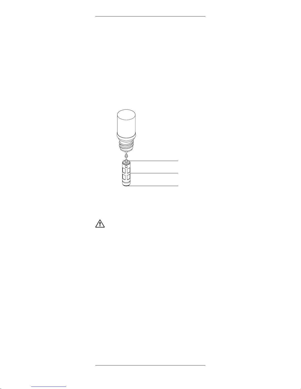
When changing the electrolyte, the membrane body or
the interior body, please observe the following instructions (see also the following illustration):
Attention! Make sure that this maintenance step is
carried out in clean place.
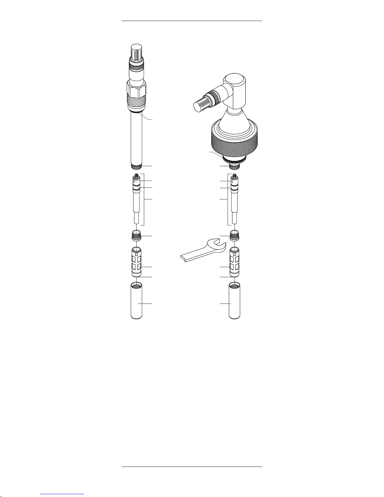
1. Unscrew the cap sleeve from the sensor shaft and
carefully pull it off the sensor.
2. Pull off the membrane body from the interior body.
If it is tight-fitted, eject by pushing it with the flat
finger tip. Before electrolyte is refilled, the membrane body must be removed from the cap sleeve.
3. Rinse the interior body with demineralized water
and carefully dab it dry with a paper tissue.
Note: steps 4 to 7 may only be carried out when
changing the interior body.
4. Unscrew the retainer nut of the interior body with
an adjustable wrench or with a 3/8" wrench.
5. Remove the interior body by pulling it out of the
sensor shaft. If necessary use a plier.
Warning! Do not twist the interior body. Otherwise the connection pins can be damaged.
InPro 6800 Series O2Sensor 12/25 mm 25
© 02 / 17 Mettler-Toledo GmbH InPro 6800
Printed in Switzerland 52 200 953
6. Insert the new interior body in the sensor shaft.
Turn the interior body in the shaft until the slit of the
interior body is aligned with the pin placed in the
shaft.
7. Press the body in the shaft and screw the new
retainer nut in place.
8. Examine the O-rings visually for mechanical
defects, and replace if necessary.
9. Half-fill the new membrane body with O
2
electrolyte and make sure that all bubbles are
removed. Air bubbles can be removed by care fully
tapping on the membrane body.
10. Slip the membrane body over the interior body
while holding the sensor in a vertical position. The
excess electrolyte will be displaced and have to be
removed with a paper tissue.
Attention! No electrolyte, sample media or contamination may be present between the membrane
body and the cap sleeve. Please check carefully.
11. Carefully slip the cap sleeve over the fitted
membrane body, holding the sensor in a vertical
position and screw it tight. The cap sleeve must be
clean and dry.
12. After each exchange of electrolyte or membrane
body, the sensor has to be repolarized and re calibrated.
1
/
2
1
/
2
O2electrolyte
26 InPro 6800 Series O2Sensor 12/25 mm
InPro 6800 © 02 / 17 Mettler-Toledo GmbH
52 200 953 Printed in Switzerland
3/8"
Slit
O-ring
9.0x1.0 mm, Silicone FDA/USP VI
O-ring
20.29x2.62 mm,
Silicone FDA/USP VI
O-ring
10.77x2.62 mm,
Silicone FDA/USP VI
O-rings
Interior body
Retainer nut
(O-ring inside)
Membrane body
Cap sleeve (N-type)
O-ring
Silicone FDA/USP VI

InPro 6800 Series O2Sensor 12/25 mm 27
© 02 / 17 Mettler-Toledo GmbH InPro 6800
Printed in Switzerland 52 200 953
7 Storage
The sensor can be stored for several months filled with
O2electrolyte (order no. 30 298 424) as long as the
protective cap is in place. In order to avoid the 6-hour
polarization time before reuse of the sensor, it can be
kept stored connected to the METTLER TOLEDO O
2
Sensor-Master InPro 6800.
Attention! The electrolyte should be replaced before
use if the storage period exceeds 3 months.
If the storage period exceeds 6 months, the sensor
should be stored dry, i.e. without any electrolyte in the
membrane body.
Attention! A sensor being stored dry (without
electrolyte in the membrane body) may on no account
be connected to the O2Sensor-Master InPro 6800.
8 Product specification
8.1 Certificates
Each sensor is delivered with a set of 3.1 B certificates
(complying with EN 10204.3/1.B).
All wetted metal parts (sensor shaft, cap sleeve and
membrane body) are identified with a engraved
symbol corresponding to the heat number on the
paper certificate delivered with the sensor.
Each wetted metal part (sensor shaft, cap sleeve and
membrane body) is polished in order to get a surface
roughness lower than 0.4µm (16µin). This represents
a roughness grade number of N5 (according to ISO
1320:1992).

28 InPro 6800 Series O2Sensor 12/25 mm
InPro 6800 © 02 / 17 Mettler-Toledo GmbH
52 200 953 Printed in Switzerland
8.2 Specifications
Attention! Please refer to the supplementary sheet
52 201 146 if the sensor, together with the membrane
body T-6800 gas, is been used for measurement of
oxygen partial pressure in gases. This supplementary
sheet is only included in the packaging of T-6800 gas
membrane bodies and kits.
InPro 6800
Measurement principle Amperometric/Polarographic
Working conditions
Pressure resistance measurement 0.2 – 6 bar absolute
[2.9 – 87.0 psi absolute]
Mechanical pressure resistance max. 12 bar absolute
[174.0 psi absolute]
Measuring temperature range 0…80°C [32…176°F]
Temperature range – 5…140 °C [23…284°F]
(sterilizable/autoclavable)
Construction
Temperature compensation Automatic with built-in RTD
Cable connection VarioPin (IP68) straight or angled
K8S straight (digital ISM sensors)
O-ring material Silicone FDA and
USP VI approved
Membrane material PTFE/ Silicone/ PTFE
(reinforced with steel mesh)
Wetted metal parts Stainless steel
Special material on request
Surface roughness of N5 (R
a
< 0.4 µm [16µin])
wetted metal parts (ISO 1320:1992)
Quick disconnect interior body Standard
Cathode Pt
Anode Ag
Guard ring No
Dimensions
Sensor diameter 12 or 25 mm (0.47" or 0.98")
Immersion length (a) for 12mm sensor 70, 120, 220, 320, 420 mm
(2.8, 4.7, 8.66, 12.6, 16.54")
Immersion length (a) for 25mm sensor 80,160, 260, 360 mm
(3.15, 6.3, 10.24, 14.17")
Performances
Detection limit 6 ppb
Accuracy ≤ ±[1% + 6 ppb]
of reading in liquids
Response time at 25°C / 77 °F (air ➝ N2) 98 % of final value <90 s
Sensor signal in ambient air (25 °C /77°F) 50…110 nA
Residual signal in oxygen-free medium <0.1 %
of the signal in ambient air
Maximum flow error ≤5%
Certification
EHEDG, 3A Yes
3.1 B (EN 10204.3/1.B) Yes
ATEX certificate Yes
FM Approval Yes
FDA / USP VI Yes
Quality control Yes
Compatibility
with METTLER TOLEDO transmitters see ”Section 9.4”
with METTLER TOLEDO housings see ”Section 9.5”
InPro 6800 Series O2Sensor 12/25 mm 29
© 02 / 17 Mettler-Toledo GmbH InPro 6800
Printed in Switzerland 52 200 953
9 Ordering information
For more detailed information refer to the technical
data sheet. Ask your local distributor.
9.1 Sensors
Sensor without ISM functionality
Immersion 12 mm diameter 25 mm diameter
length (a) straight angled straight angled
70 mm (2.8") 52 200 964 52 200 969 –– ––
80 mm (3.2") –– –– 52 200 974 52 200 978
120 mm (4.7") 52 200 965 52 200 970 –– ––
160 mm (6.3") –– –– 52 200 975 52 200 979
220 mm (8.7") 52 200 966 52 200 971 –– ––
260 mm (10.2") –– –– 52 200 976 52 200 980
320 mm (12.6") 52 200 967 52 200 972 –– ––
360 mm (14.2") –– –– 52 200 977 52 200 981
420 mm (16.5") 52 200 968 52 200 973 –– ––
9.2 Accessories
Accessories Order no.
O2Sensor-Master InPro 6800 52 200 892
O2Sensor-Simulator 52 200 891
Adapter T82 socket – VP plug 52 200 939
Adapter VP socket – T82 plug 52 200 940
VP cable VP6-ST/3 m 52 300 108
VP cable VP6-ST/5 m 52 300 109
VP cable VP6-HT/3 m 52 300 112
VP cable VP6-HT/5 m 52 300 113
VP cable VP8-ST/3 m 52 300 354
VP cable VP8-ST/5 m 52 300 355
VP cable VP8-HT/3 m 52 300 361
VP cable VP8-HT/5 m 52 300 362
Oxygen zeroing gel (3× 25 ml) 30 300 435
For other cable lengths or types, please contact your local METTLER TOLEDO
representative.
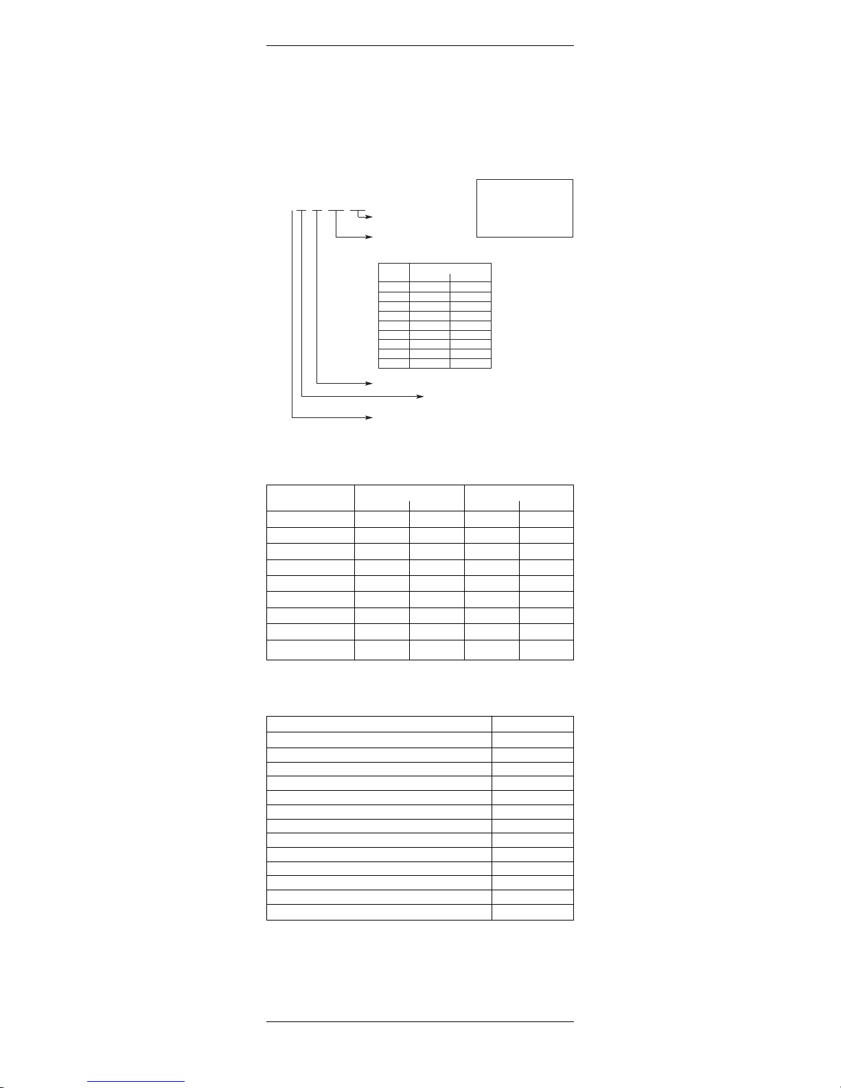
Intelligent Sensor Management (ISM) O2sensor configuration
InPro 6 _ _ _ / _ _ / _ _ _ / _ _ _
Blank: Standard functionality
ISM: Intelligent Sensor Management
Immersion length (a) in mm
For diameter/immersion lengths combinations,
please see table below:
(a) InPro 68xx
[ 12 [ 25
070 ✓ –
080 – ✓
120 ✓ –
160 ✓✓
220 ✓ –
260 – ✓
320 ✓ –
360 – ✓
420 ✓ –
Sensor diameter: 12 = 12 mm; 25 = 25 mm
00: VP Plug head, straight
10: VP Plug head, angled
8: InPro 68xx
Example configuration:
InPro 6800/12/120/ISM
➝ Sensor with ISM functionality
InPro 6810/25/260
➝ Sensor without ISM functionality
30 InPro 6800 Series O2Sensor 12/25 mm
InPro 6800 © 02 / 17 Mettler-Toledo GmbH
52 200 953 Printed in Switzerland
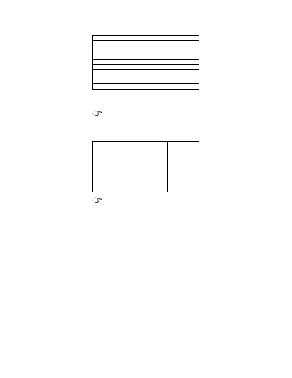
9.3 Spare parts
Spare parts Order no.
Membrane body, single T-96 52 200 071
Membrane kit T-96 52 200 024
(4 membrane bodies, 1 O-ring set,
25 ml Electrolyte bottle)
Membrane bodies (20 pcs.) T-96 52 200 791
O2Electrolyte pack (3× 25 ml) 30 298 424
Interior body InPro 6800 52 200 899
(with quick disconnect)
Cap sleeve N-type 52 200 037
Cap sleeve with protective cage P-type 52 200 038
9.4 Recommended transmitter
Note: Ask your local distributor or refer to the techni-
cal data sheet.
9.5 Recommended housings
Housings 12 mm Ø 25 mm Ø
Static housings
INGOLD ”safety
weld-in socket” – 3
InFit 761 CIP 3 –
Retractable housings
InFit 777 e 3 –
InFit 797 e 3 –
Immersion housing
InDip
®
550 3 –
Note: The housings are available in different versions.
Please contact your distributor to get the right odering
information.
Please ask
your local
METTLER
TOLEDO
representative.
 Loading...