

Mettler Toledo InPro 6050 Instruction Manual
InPro 6050 Series O2Sensors
Instruction manual
Bedienungsanleitung
Instructions d’utilisation
InPro 6050
52 200 251

InPro 6050 Series O2Sensor
InPro 6050 © 02 / 16 Mettler-Toledo GmbH
52 200 251 Printed in Switzerland
2
English Page 3
Deutsch Seite 15
Français Page 27

InPro 6050 Series O2Sensor
© 02 / 16 Mettler-Toledo GmbH, InPro 6050
Printed in Switzerland 52 200 251
3
InPro 6050 Series O2Sensors
Instruction manual

InPro 6050 Series O2Sensor
InPro 6050 © 02 / 16 Mettler-Toledo GmbH
52 200 251 Printed in Switzerland
4
Contents
Page
1. Product description . . . . . . . . . . . . . . . . . . . 5
1.1. Utilization, conformity, identification . . . . .5
1.2. Key data and characteristics . . . . . . . . . 5
1.3. Equipment features and scope of delivery 6
2
. Safety . . . . . . . . . . . . . . . . . . . . . . . . . . . . . 7
2.1. Signs and symbols . . . . . . . . . . . . . . . . 7
2.2. Safety precautions . . . . . . . . . . . . . . . . 7
3. Your equipment . . . . . . . . . . . . . . . . . . . . . . 7
3.1. Design / description . . . . . . . . . . . . . . . . 7
3.2. Functions . . . . . . . . . . . . . . . . . . . . . . . 8
3.3. Integration in measuring system . . . . . . . 8
4. Start-up . . . . . . . . . . . . . . . . . . . . . . . . . . . 8
4.1. Installation . . . . . . . . . . . . . . . . . . . . . . 8
4.2. Connection . . . . . . . . . . . . . . . . . . . . . . 8
4.3. Initial start-up . . . . . . . . . . . . . . . . . . . . 9
5. Operation . . . . . . . . . . . . . . . . . . . . . . . . . 10
5.1. Operation of the equipment . . . . . . . . . . 10
5.2. Measurement in power failure . . . . . . . . 10
5.3. Errors and corrective actions . . . . . . . . . 10
5.4. Storage . . . . . . . . . . . . . . . . . . . . . . . 10
6. Maintenance . . . . . . . . . . . . . . . . . . . . . . . 11
6.1. Safety precautions . . . . . . . . . . . . . . . . 11
6.2. Cleaning and care . . . . . . . . . . . . . . . . 11
6.3. Replacing membrane & electrolyte . . . . . 11
6.4. Calibrating the sensor . . . . . . . . . . . . . 12
6.5. Troubleshooting and rectification work . . 12
7. Shut down and waste disposal . . . . . . . . . . 13
7.1. Shut down . . . . . . . . . . . . . . . . . . . . . 13
7.2. Waste disposal . . . . . . . . . . . . . . . . . . 13
8. Spare parts . . . . . . . . . . . . . . . . . . . . . . . . 13

InPro 6050 Series O2Sensor
© 02 / 16 Mettler-Toledo GmbH, InPro 6050
Printed in Switzerland 52 200 251
5
1
. Product description
1.1. Utilization, conformity, identification
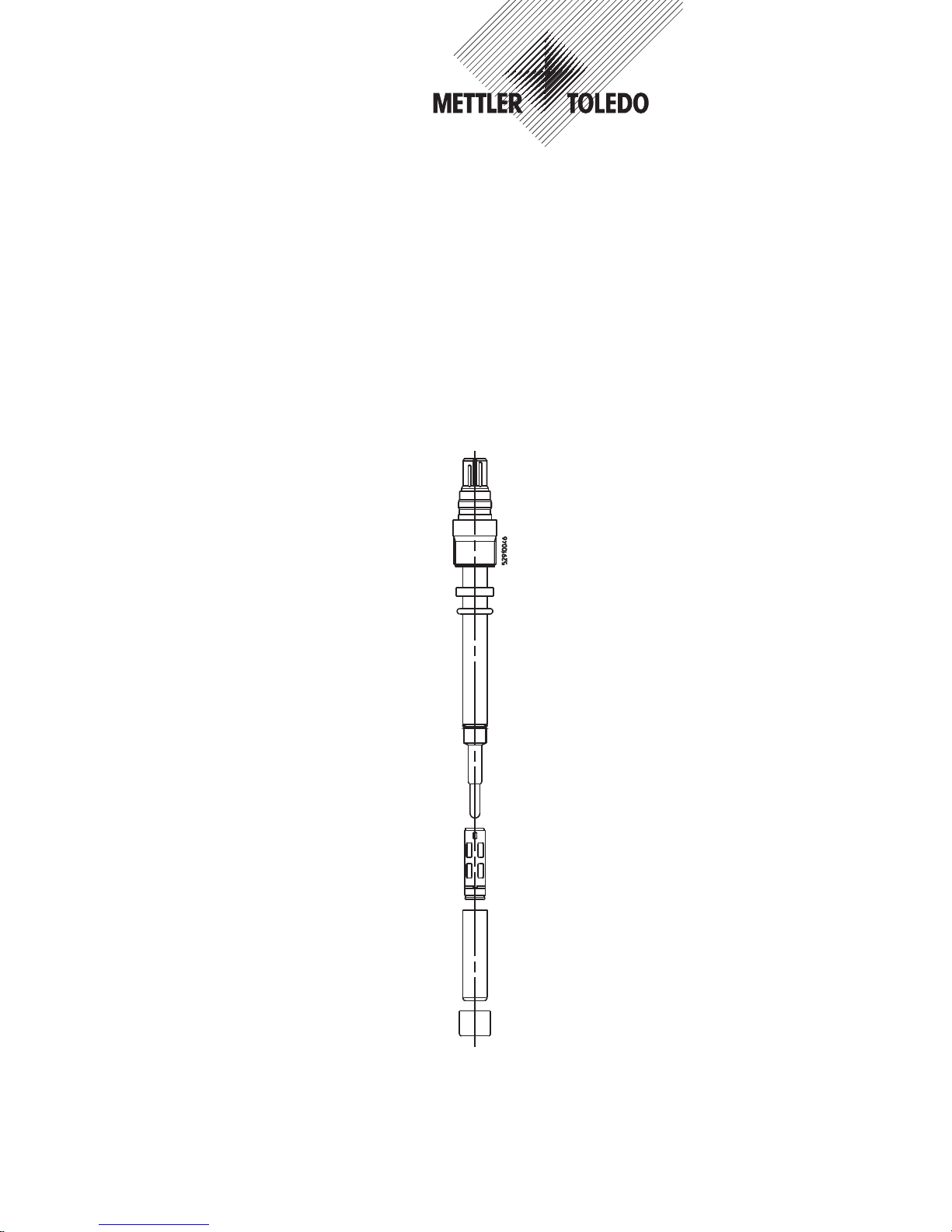
The InPro 6050 is a polarographic oxygen sensor
designed for the simultaneous measurement of diss
olved oxygen and temperature in water applications.
The robust detachable connector VP (Vario Pin) provides the same, waterproof performance of fixed cable electrodes, with the advantage of a detachable
connector for easy sensor maintenance and replacem
ent.
T
he serial number is engraved on the sensor thread
for traceability.
1.2. Key data and characteristics
Technical data
Length 120 mm
Diameter 12mm
Connector VarioPin connector VP-4G
IP 68
Cable VP Cable
Temperature sensor NTC
Material
Shaft PPS
Membrane T-96 PTFE/Silicone/PTFE
(reinforced with steel mesh)
O-Rings Viton®, silicone
Working conditions
Temperature range 0...60°C
Humidity 0...100%
Media The sensor is designed for
use in water
InPro 6050 Series O2Sensor
InPro 6050 © 02 / 16 Mettler-Toledo GmbH
52 200 251 Printed in Switzerland
6
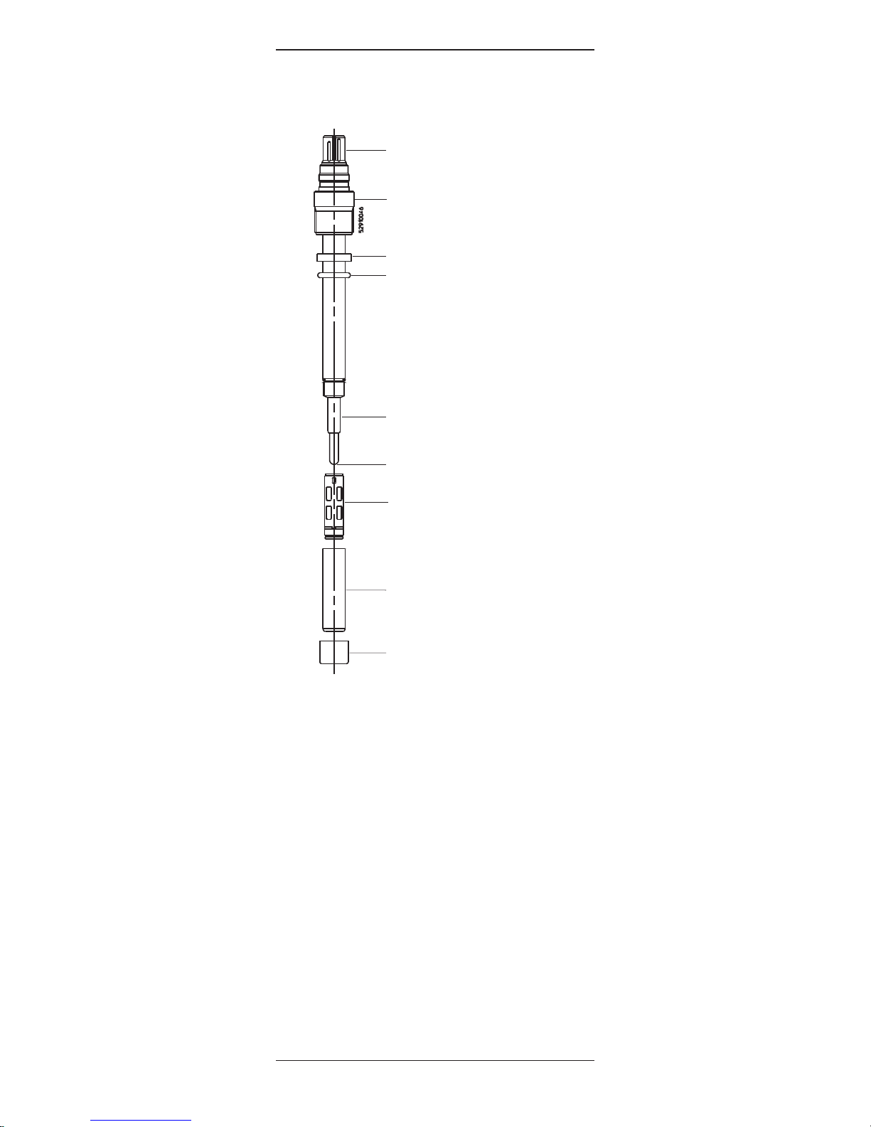
1.3. Equipment features and scope of delivery
1
2
3
4
7
8
6
5
9
1 VP Connector
2 Pg 13.5 threaded sleeve
3 Washer
4 O-ring
5 Anode
6 Cathode
7 Membrane body
8 Cap sleeve
9 Protection cap
The oxygen sensor is shipped with a T-96 type membrane body in place. This membrane type has an additional PTFE layer on the process side for increased
durability. It also has a built-in temperature device
(NTC) that allows compensation for membrane permeability.

InPro 6050 Series O2Sensor
© 02 / 16 Mettler-Toledo GmbH, InPro 6050
Printed in Switzerland 52 200 251
7
2
. Safety
2
.1. Signs and symbols
The following symbols are used in this instruction
m
anual:
D
anger: warning of a danger which could
be fatal or lead to severe bodily harm
Caution: warning of a possibly dangerous
situation which could lead to minor injuries and/or material damage
Notice: reference to working methods
which facilitate use of equipment
2.2. Safety precautions
Please read this instruction manual entirely before
using the sensor.
The InPro 6050 is built under the strict quality guidelines for ISO 9001.
3. Your equipment
3.1. Design/description
The sensor is made of:
• A VP (VarioPin) connector
• A plastic shaft which contains an anode (silver)
and a cathode
• A membrane body filled with electrolyte
• A plastic cap sleeve

InPro 6050 Series O2Sensor
InPro 6050 © 02 / 16 Mettler-Toledo GmbH
52 200 251 Printed in Switzerland
8
3.2 Functions
This sensor technology is based on a polarographic
O2measurement (Clark type), which can be summarized as follow:
• It consists of a working electrode (cathode), a
counter electrode (anode) and an oxygen permeab
le membrane which separates the electrodes
from the medium.
• The transmitter supplies a constant voltage to the
cathode (polarization voltage). We recommend a
–675mV polarization voltage for aqueous applications.
• The oxygen molecules migrate from the medium
to the electrodes through the membrane and are
reduced at the cathode. At the same time an oxidation takes place at the anode. The electrolyte
completes the electric circuit between the anode
and the cathode.
3.3. Integration in measuring system
A complete measuring loop consists of a sensor,
a cable and a transmitter
4. Start-up
4.1. Installation
Before installation, we recommend you to:
• change the electrolyte as described in § 6.3 (you
do not need to change the membrane body)
• visually check the membrane for cracks or indents
(in case of damaged membrane, the membrane
body must be changed)
The sensor can be installed in pipes by using a flowthrough housing (InFlow 751) or a stationary housing (InFit 761). The sensor can also be immersed
directly in a tank by using an immersion housing (InDip 550/524).
Please refer to the instruction manuals of these housings for installation instructions.
Important: to guarantee a tight seal, a
washer must be used together with an
O-ring.
The sensor should be installed in a place where there
is enough fluid circulation (at least 1liter per hour
should pass by the head of the sensor). Placing the
sensor in a dead spot would lead to false results.
If the sensor is installed in a pipe, it is preferable to
install it at an angle against the flow to achieve the
best possible measurement.
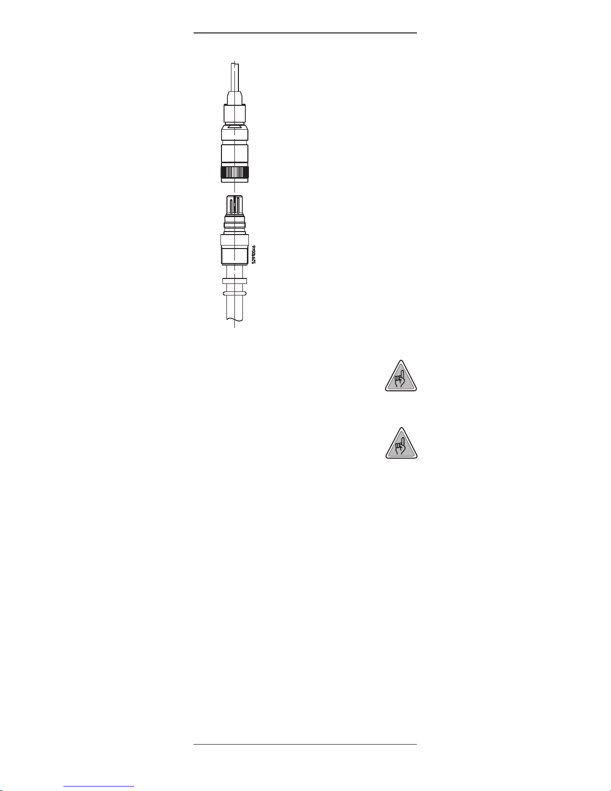
4.2. Connection
To connect the sensor to the transmitter, a VP cable
should be used. This ensures a secure link between
the transmitter and the sensor under harsh industrial
conditions. The robust watertight IP 68 connector
housing guarantees maximum process safety. The
slit of the connector should be aligned with the pin of
the plug, and the two parts should be then screwed
tightly together.
InPro 6050 Series O2Sensor
© 02 / 16 Mettler-Toledo GmbH, InPro 6050
Printed in Switzerland 52 200 251
9
For instructions concerning the connection
of the VP cable to the transmitter, please
refer to the transmitter instruction manual.
4.3. Initial start-up
Notice: The protective cap at the tip of the
sensor should be removed before putting
the sensor into operation.
When the sensor is installed for the first time or has
been disconnected from the voltage source (polarization voltage from the transmitter or polarization module) for longer than 5 minutes, the sensor must be
polarized before calibration or the first measurements. This can be achieved by connecting the sensor to the transmitter or a polarization module for at
least six hours. The recommended polarization voltage is –675mV.
VP cable
Plug
Pin
Slit
Connector
InPro 6050

InPro 6050 Series O2Sensor
InPro 6050 © 02 / 16 Mettler-Toledo GmbH
52 200 251 Printed in Switzerland
1
0
5
. Operation
5
.1. Operation of the equipment
Once the sensor is properly calibrated (see § 6.4)
a
nd installed, you should refer to the instruction manual of the transmitter to learn how to operate the
complete system.
5.2. Measurement in power and failure
In case of power failure for more than
10-15 minutes the sensor must be repolarized over
a period of 6 hours (see Chapter 4.3).
In case of drop out for 5 to 15 minutes, the sensor
must be polarized for 45 minutes.
In case of a power drop-out less than 5 minutes, a
polarization time of 10 minutes is sufficient.
5.3. Errors and corrective actions
Make sure the sensor is mounted properly in a vertical position (VP connector up), or at a 15° angle
(against the flow) to prevent the accumulation of air
bubbles on the sensor head.
5.4. Storage
The sensor and the membrane must be cleaned
before storing the sensor.
The sensor can be stored for several months, provided it is filled with O2electrolyte and the protective
cap is placed over the membrane. To avoid the
6-hour polarization requirement after storage, the
sensor can be stored connected to a polarization
module.

InPro 6050 Series O2Sensor
© 02 / 16 Mettler-Toledo GmbH, InPro 6050
Printed in Switzerland 52 200 251
11
6
. Maintenance
When used in water applications, the sensor is desig
ned to require minimal service. However in some
cases it can be necessary to recalibrate the sensor or
to change the electrolyte or the membrane body.
6.1. Safety precautions
Danger: the electrolyte has an alkaline
pH-value of 13. Contact of the electrolyte
with the skin, especially mucous memb
rane or eyes, should be avoided. If such
contact occurs, the affected area should
be well rinsed with running water. Get medical attention if adverse signs appear.
As contact with the electrolyte is very likely during the
exchange of electrolyte or membrane body, the use
of protective gloves is recommended.
6.2. Cleaning and care
The sensor can be gently cleaned with soapy water
(or with a mild bleach) and rinsed thoroughly.
Inspect the membrane. If it has cracks or shows longer response time, then it should be replaced as follow:
6.3. Replacing the membrane and the electrolyte
Please follow the following instructions to change the
membrane body and the electrolyte:
a) Unscrew the cap sleeve from the shaft and
carefully pull it off the sensor.
b) Pull off the membrane body from the interior
body. If it remains inside the cap sleeve, eject by
pushing it with the flat finger tip. Before electrolyte
is refilled, the membrane body must be removed
from the cap sleeve.
c) Clean the interior body with a soft tissue.
d) Check the O-rings for mechanical defects and
replace if necessary.
e) Half fill the membrane body with O2electrolyte
and make sure it is bubble-free. Air bubbles can
be removed by carefully tipping on the membrane
body.
f) Slowly slip the membrane body over the interior
body while holding the sensor in a vertical position.
The excess electrolyte will be displaced and
should be wiped off with a paper tissue.
g) Carefully slip the cap sleeve over the fitted
membrane body and screw it down. The cap
sleeve must be clean and dry.
h) After each replacement of the electrolyte or of the
membrane, the sensor must be polarized over a
period of 6 hours.
i) When the sensor is polarized and connected to
the transmitter, it is necessary to start by recalibrating the system.

InPro 6050 Series O2Sensor
6.4. Calibrating the sensor
• For an air calibration, the sensor must be removed
from the medium, gently cleaned and dried.
W
ater droplets on the membrane must be removed, as they prevent the sensor from being correctly calibrated.
• To calibrate in water or sample medium, you must
know the exact oxygen concentration and ensure
that equilibrium between the air and the medium is
r
eached (this may take quite a long time).
Make sure that all other parameters (temperature
and pressure) are constant during the calibration.
Please note also that a minimum flow rate is necessary.
• For detailed calibration instructions, please refer to
the transmitter instruction manual.
• In case of an error message from the transmitter
after a calibration, clean the sensor, change the electrolyte and replace the membrane if this is damaged.
6.5. Troubleshooting and rectification work
On a regular basis, you can take the sensor out of
the water, clean and dry it. If it gives a reading of
100% saturation, the sensor does not need to be recalibrated.
If the sensor gives too high or too low values, it
should be recalibrated.
After a long storage time (more than 6 months) or after a certain period of time in operation (typically one
year for water applications), the electrolyte should be
replaced. Replace damaged membranes as necessary.
If after a calibration the sensor still gives too high or
too low values, you should change the electrolyte
and the membrane.
InPro 6050 © 02 / 16 Mettler-Toledo GmbH
52 200 251 Printed in Switzerland
1
2
 Loading...