

Mettler Toledo InPro 6000G Instruction Manual
© 12 /15 Mettler-Toledo GmbH InPro 6000 G – Series
Printed in Switzerland 52 206 477
InPro®6000G Series
Gas Phase Oxygen Sensors
Instruction manual
Bedienungsanleitung
Instructions d’utilisation

2 InPro 6800G/6850i G/6900i G/6950i GO212 mm
InPro 6000 G – Series © 12 / 15 Mettler-Toledo GmbH
52 206 477 Printed in Switzerland
English Page 3
Deutsch Seite 42
Français Page 82
© It is forbidden to reprint this Instruct ion Manual in whole or par t. No part of this
manual may be repro duced in any form, or modified, co pied or distributed using
electronic systems, in particular in the form of photo copies, photographs , magnetic
or other recordings, without written c onsent of Mettler-Tol edo Gmb H, Process Analytics,
CH-8902 Urdorf, Switzerland.
All rights reserved, in particular reprod uction, translation a nd patenting/registration.

InPro 6800G/6850i G/6900i G/6950i G O212 mm 3
© 12 /15 Mettler-Toledo GmbH InPro 6000 G – Series
Printed in Switzerland 52 206 477
InPro 6800G/6850i G/6900i G/6950i G O212 mm 3
1 Introduction.....................................................................4
2 Important notes ...............................................................5
2.1 Notes on operating instructions ..........................................5
2.2 Intended use ....................................................................5
2.3 Safety instructions.............................................................6
2.4 Examples of some typical applications................................7
2.5 Use in Ex-zones ...............................................................7
2.6 Ex-classification ATEX .......................................................8
2.6.1 Introduction......................................................................8
2.6.2 Rated data .......................................................................8
2.6.3 Special conditions.............................................................9
2.7 Ex-classification FM approved..........................................10
3 Product description........................................................11
3.1 General information ........................................................11
3.2 Principle ........................................................................11
3.3 Enhanced diagnostics (only for ISM types available) ..........13
3.4 Scope of delivery ............................................................14
3
.5 Equipment features .........................................................15
4 Installation....................................................................16
4.1 Mounting the sensor........................................................16
4.2 Connection ....................................................................16
4.2.1 Connecting the sensor to a AK9 cable ...............................16
4.2.2 Connecting the cable to the transmitter ..............................17
5 Operation ......................................................................18
5.1 Start-up and polarizing....................................................18
5.2 Calibration .....................................................................19
5.2.1 Purpose of calibration .....................................................19
5.2.2 What you have to know for calibration ..............................19
5.2.3 Single point calibration....................................................20
5.2.4 Dual point calibration......................................................20
6 Maintenance .................................................................21
6.1 Inspection of the sensor...................................................21
6.1.1 Visual inspection ............................................................21
6.1.2 Using the METTLER TOLEDO O
2
sensor master ...................22
6.1.3 Testing the sensor via a transmitter...................................23
6.1.4 ISM design.....................................................................24
6.2 Changing the electrolyte,
the membrane body or the interior body ............................25
7 Storage.........................................................................28
8 Product specification .....................................................29
8.1 Certificates .....................................................................29
8.2 Specifications.................................................................30
9 Ordering information .....................................................32
9.1 Sensors .........................................................................32
9.2 Transmitter.....................................................................32
9.3 Accessoires....................................................................32
9.4 Spare parts ....................................................................33
9.5 Cables...........................................................................33
9.6 Recommended housings .................................................33
10 Theory of the polarographic sensor.................................34
10.1 Introduction....................................................................34
10.2 Principle of the design of an oxygen electrode....................34
10.3 Parameters determining current ........................................38
10.4 Polarization voltage ........................................................38
10.5 Temperature...................................................................39
10.6 Dependence on flow........................................................39
10.7 Oxygen partial pressure – oxygen concentration.................39
Contents

4 InPro 6800G/6850i G/6900i G/6950i GO212 mm
InPro 6000 G – Series © 12 / 15 Mettler-Toledo GmbH
52 206 477 Printed in Switzerland
1
Introduction
Thank you for buying the InPro 6800G/6850 iG/
6900 iG / 6950 iG sensor from METTLER TOLEDO.
The construction of the InPro series employs leading
edge tech nology and complies with safety regulations currently in force. Notwithstanding this, improper use could lead to hazards for the user
or a third-party, and/or adverse effects on the plant
or other equipment.
Therefore, the operating instructions must
be read and understood by the persons involv ed
before work is started with the sensor.
The instruction manual must always be stored close
at hand, in a place accessible to all people working
with the InPro sensor.
If you have questions, which are not or insufficiently
answered in this instruction manual, please contact
your METTLER TOLEDO supplier. He will be glad to
assist you.

InPro 6800G/6850i G/6900i G/6950i G O212 mm 5
© 12 /15 Mettler-Toledo GmbH InPro 6000 G – Series
Printed in Switzerland 52 206 477
2
Important notes
2
.1 Notes on operating instructions
These operating instructions contain all the information
needed for safe and proper use of the InPro 6800G /
6850iG/6900 iG/6950 iGsensor.
The operating instructions are intended for personnel
entrusted with the operation and maintenance of the
sensors. It is assumed that these persons are familiar
with the equipment in which the sensor is installed.
Warning notices and symbols
This instruction manual identifies safety instructions
and additional information by means of the following
symbols:
This symbol draws attention to safety instructions
and warnings of potential danger which, if neglected, could result in injury to persons and/or damage
to property.
This symbol identifies additional information and
instructions which, if neglected, could lead to
defects, inefficient operation and possible loss of
production.
2.2 Intended use
METTLER TOLEDO InPro 6800 G/6850iG/6900iG/
6950 i G sensors are intended solely for inline
measurement of the oxygen partial pressure in
liquids and gases, as described in this instruction
manual.
Any use of these sensors which differs from or exceeds the scope of use described in this instruction
manual will be regarded as inappropriate and incompatible with the intended purpose.
The manufacturer/ supplier accepts no responsibility
whatsoever for any damage resulting from such
improper use. The risk is borne entirely by the user /
operator.
Other prerequisites for appropriate use include:
– compliance with the instructions, notes and
requirements set out in this instruction manual.
– acceptance of responsibility for regular inspection,
maintenance and functional testing of all asso ci ated components, also including compliance with
local operational and plant safety regulations.
– compliance with all information and warnings
given in the documentation relating to the products
used in conjunction with the sensor (housings,
transmitters, etc.).
– observance of all safety regulations governing the
equipment in which the sensor is installed.

6 InPro 6800G/6850i G/6900i G/6950i GO212 mm
InPro 6000 G – Series © 12 / 15 Mettler-Toledo GmbH
52 206 477 Printed in Switzerland
– correct equipment operation in conformance with
the prescribed environmental and operational conditions, and admissible installation positions.
– consultation with Mettler-Toledo Process Analytics
in the event of any uncertainties.
2.3 Safety instructions
– The plant operator must be fully aware of the
potential risks and hazards attached to operation
of the particular process or plant. The operator is
responsible for correct training of the workforce, for
signs and markings indicating sources of possible
danger, and for the selection of appropriate, stateof-the-art instrumentation.
– It is essential that personnel involved in the
commissioning, operation or maintenance of
these sensors or of any of the associated equipment (e.g. housings, transmitters, etc.) be properly trained in the process itself, as well as in the
use and handling of the associated equipment.
This includes having read and understood this
instruction manual.
– The safety of personnel as well as of the plant
itself is ultimately the responsibility of the plant
operator. This applies in particular in the case of
plants operating in hazardous zones.
– The oxygen sensors and associated components
have no effect on the process itself and cannot
influence it in the sense of any form of control
system.
– Maintenance and service intervals and schedules
depend on the application conditions, composition of the sample media, plant equipment and
signi ficance of the safety control features of the
measuring system. Processes vary considerably,
so that schedules, where such are specified, can
only be regarded as tentative and must in any
case be individually established and verified by
the plant operator.
– Where specific safeguards such as locks, labels,
or redundant measuring systems are necessary,
these must be provided by the plant operator.
– A defective sensor must neither be installed nor
put into service.
– Only maintenance work described in this operat-
ing instruction may be performed on the sensors.
– When changing faulty components, use only
original spare parts obtainable from your
METTLER TOLEDO supplier (see spare parts list,
“Section 9.4”).
InPro 6800G/6850i G/6900i G/6950i G O212 mm 7
© 12 /15 Mettler-Toledo GmbH InPro 6000 G – Series
Printed in Switzerland 52 206 477
– No modifications to the sensors and the acces-
sories are allowed. The manufacturer accepts no
responsibility for damages caused by unauthorised modifications. The risk is borne entirely by
the user.
2.4 Examples of some typical applications
Below is a list of examples of typical fields of
application for the oxygen sensors. This list is
not exhaustive.
Measurement in liquids:
– Biotech
– Chemical applications
– Brewing
– Beverage filtration
– Filling stations
Measurement in gases:
– CO2recovery
– CO2purity
– Product storage
– Inert production
– Offgas monitoring
2.5 Use in Ex-zones
Attention!
For an installation in Ex-zones please read the
guidelines following hereafter:
1258
Ex-classification ATEX:
Ex ia IIC T6/T5/T4/T3 Ga/Gb
Ex ia IIIC T69°C/T81°C/T109°C/T161°C Da/Db
Number of the test certificate:
SEV 14 ATEX 0169 X
IECEx SEV 14.0026X
Ex-classification FM approved:
IS/ I, II, III /1/ABCDEFG /T6 Ta = 60 °C
- 53 800 002; Entity

8 InPro 6800G/6850i G/6900i G/6950i GO212 mm
InPro 6000 G – Series © 12 / 15 Mettler-Toledo GmbH
52 206 477 Printed in Switzerland
2.6 Ex-classification ATEX
2.6.1 Introduction
According to Directive 94/9/EC (ATEX 95) Appendix I,
the O2oxygen sensors type InPro 6XXX is a devices
of equipment group II, category 1/2G which, according to Directive 99/92/EC (ATEX 137) can be used in
zones 0/1 or 1/2 or 1 or 2 as well as gas groups IIA,
IIB and IIC, which are potentially explosive due to
combustible substances in the temperature T3 to T6.
The requirements specified in EN 60079-14 must be
observed during use / installation.
According to Directive 94/9/EC (ATEX 95) Appendix
I, the O2oxygen sensors type InPro 6XXX is a devices of equipment group II, category 1/2D which,
according to Directive 99/92/EC (ATEX 137) can be
used in zones 20/21 or 21/22 or 21 or 22, which
are potentially explosive due to combustible dust.
The requirements specified in EN 60079-14 must be
observed during use / installation.
For the analog version of the O2oxygen electrode, the
O2measurement circuit, temperature measurement
circuit and data chip circuit are part of the common
intrinsically safe system and are jointly connected to
and operated by a separately certified transmitter.
The digital version of the O2oxygen sensor is connected to and operated by two-wire cable to the certified transmitter.
The intrinsically safe circuits are galvanically isolated
from the non-intrinsically safe circuits up to a nominal voltage peak value of 375 V and from the earthed
parts up to a nominal voltage peak value of 30 V.
2.6.2 Rated data
Analog O2Oxygen sensor
With type of protection: intrinsic safety to Ex ia IIC
O
2
measuring circuit, temperature measuring
circuit and data chip circuit
Only for connection to certified intrinsically safe circuits. Maximum values:
Ui≤ 16 V, Ii≤ 190 mA, Pi≤ 200 mW
Li= 0 (effective internal inductance)
Ci= 900 pF (effective internal capacitance)
The values above apply, each as the sum of all the
individual circuits of the associated intrinsically safe
supply and evaluation unit (transmitter).
Digital O
2
Oxygen sensor
With type of protection: intrinsic safety to Ex ia IIC
Two-wire current circuit
Only for connection to certified intrinsically safe circuits. Maximum values:

InPro 6800G/6850i G/6900i G/6950i G O212 mm 9
© 12 /15 Mettler-Toledo GmbH InPro 6000 G – Series
Printed in Switzerland 52 206 477
Ui≤ 16 V, Ii≤ 30 mA, Pi≤ 50 mW
Li= negligible
Ci= negligible
2.6.3 Special conditions
–
The relationship between the maximum permissi-
b
le ambient or media temperature and tempera-
t
ure class, for category 1G applications, zone 0, is
s
hown in the following table:
Temperature class Max. ambient or
media temperature
T 6 68 °C
T 5 80 °C
T 4 108 °C
T 3 160 °C
– The relationship between the maximum permissi-
ble ambient or media temperature and temperature class, for category 1D applications, zone 20,
is shown in the following table:
Temperature class Max. ambient or
media temperature
T 69 °C 68 °C
T 81 °C 80 °C
T 109 °C 108 °C
T 161 °C 160 °C
– The capacitance and inductance of the connecting
cable has to be considered.
– The O2Oxygen sensor type InPro 6XXX can be
used in / with the fittings InFit 76*-*** or InTrac
7**-***, or in / with other suitable fittings in potentially explosive areas.
– The metal body of the O2Oxygen sensors, or the
fittings InFit 76*-*** or InTrac 7**-***, or other
appropriate fitting is optionally included in the routine pressure test of the system.
– The independent fitting used for installation of O
2
Oxygen sensor must be conductively connected to
the equipotential bonding system.
10 InPro 6800G/6850iG/6900iG/6950i GO212 mm
InPro 6000 G – Series © 12 / 15 Mettler-Toledo GmbH
52 206 477 Printed in Switzerland
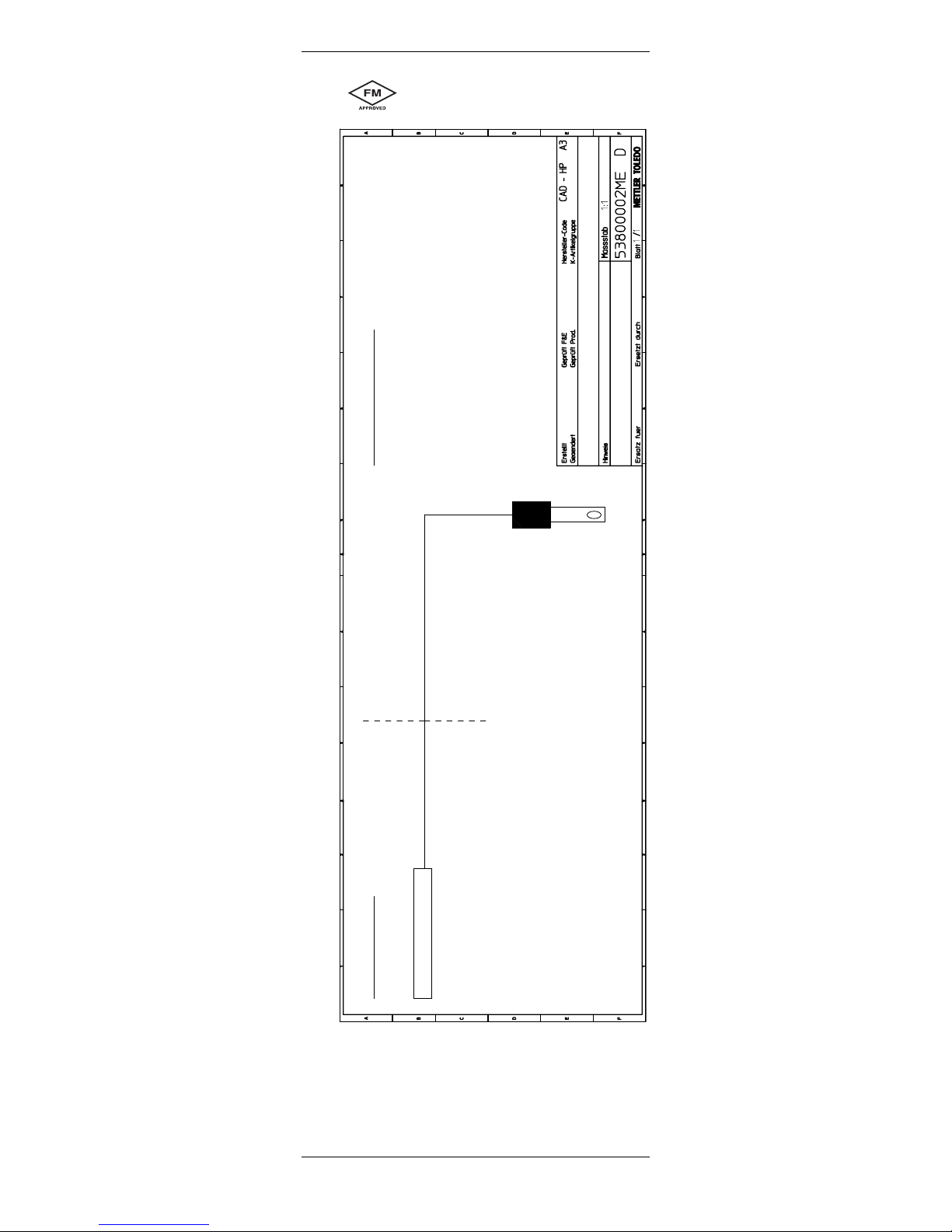
2.7 Ex-classification FM approved
Non-Hazardous Location
Hazardous (Classified) Location
Class I, Division 1, Groups A, B, C and D
Class II, Division 1, Groups E, F and G
Class III, Division 1
T6 Ta= 60 °C
Any FMRC Approved Single
Multi-Channel Barrier or Apparatus
Probe
Mettler-Toledo GmbH
Process Analytics
CH-8902 Urdorf
11/12/2003 F. Kogelmann
15/07/2005 F. Trefz
FM control drawing
Wir behalten uns alle Rechte an diesem Dokument und an allen Beilagen vor. Der Empfänger anerkennt
diese Rechte und wird die genannten Unterlagen nicht ohne unsere vorgängige schriftliche Ermächtigung
Dritten zugänglich machen oder ausserhalb des Zweckes verwenden, zu dem sie ihm übergeben worden sind.
Entity Parameters:
V
t
= 15V, I
t
= 30 mA, P
max
= 0.25W
C
i
= 0.1 µF, L
i
= 0 mH
Notes:
WARNING: substitution of components may inpair intrinsic safety.
1. No revision to this drawing is permitted without FMRC approval
2. V
max
> V
t
; I
max
> I
t
; (C
i
of all loops + C cable) < C
a
; (L
i
of all loops + L cable) < L
a
; P
max
or P
i
> P
0
3. Single Multi-Channel IS Barrier or Apparatus must be FMRC Approved
5. Installation must be in accordance with Article 500 of the NEC
®
(ANSI/NFPA 70)
and ANSI/ISA RP12.6.
4. Single Multi-Channel IS Barrier or Apparatus manufacturer's control drawings
must be followed when installing the System. IS Barrier or Equipment may be
installed within the Hazardous (Classified) location for which it is approved.

InPro 6800G/6850i G/6900i G/6950i G O212 mm 11
© 12 /15 Mettler-Toledo GmbH InPro 6000 G – Series
Printed in Switzerland 52 206 477
3 Product description
3.1 General information
The oxygen sensor series InPro 6800G/6850iG/
6900iG/6950iG with integrated temperature probe
are used for meas ure ment of oxygen at low and
medium concentrations.
InPro 6xxxiG sensors with ISM functionality offer
Plug and Measure as well as enhanced diagnostics
features.
3.2 Principle
Amperometric oxygen sensors:
The amperometric oxygen sensors of METTLER
TOLEDO base all on the same mearuring principle
according to Clark. However different series are offered, which clearly differ in the number and arrangement of their electrodes and thus in their specifications:
• The measurement system of the InPro sensors
consists of a working electrode (cathode), a
counter electrode (anode), a reference electrode
and a guard ring electrode. The measurement
system is separated from the process medium by
an oxygen permeable membrane.
• The measuring technique in principle is alike with
all sensors.
• The transmitter supplies a constant voltage be-
tween cathode and anode.
• The electrolyte creates a conductive connection
between the electrodes.
• The oxygen molecules migrate from the measure-
ment medium through the membrane to the
cathode to which the voltage is supplied and are
reduced. At the same time, oxidation takes place
at the anode.
• This causes a current to flow between the anode
and cathode which is directly proportional to the
partial pressure of oxygen (pO2) in the process
medium. With digital ISM sensors, the sensor itself converts the current into oxygen concentration
and communicates the value to the transmitter.
• The guard ring electrode of the InPro 6900iG and
6950i G built into the sensor reduces the oxygen
that migrates to the side of the cathode and can
affect the measurement. The guard ring electrode
therefore enables traces of oxygen to be precisely
determined at even the lowest concentrations.
Note: Please refer to “Section 10–Theory of the polarographic sensor” for further information.

12 InPro 6800G/6850iG/6900iG/6950i GO212 mm
InPro 6000 G – Series © 12 / 15 Mettler-Toledo GmbH
52 206 477 Printed in Switzerland
ISM Sensors:
All oxygen sensors with the index “i” (6850i G,
6900i G, 6950i G) are equipped with ISM, Intelligent
Sensor Management.
Principle: In the sensor head a chip is integrated,
which takes over the entire monitoring and control of
the sensor and, beyond that, stores all sensor data.
This chip is responsed via the transmitter.
The following data are available permanently in the
sensor:
– type of sensor
– serial no.
– software version
– hardware version
– order no.
– operating time
– calibration time and calibration date
– calibration table
To check the system, the following indicators are
monitored:
– temperature
– slope
– zero current
– air current
– polarization voltage
– cathode current and voltage
Based on these informations, the transmitter calculates a wear monitor and displays it depending upon
transmitter type differently. (see the respective instruction manuals)
ISM enables the connection of the digital sensor to
the iSense™ Asset Suite. The user-friendly software
allows to manage all sensor information and store it
in a data base. Furthermore, the sensor can be calibrated via the iSense™ software.

InPro 6800G/6850i G/6900i G/6950i G O212 mm 13
© 12 /15 Mettler-Toledo GmbH InPro 6000 G – Series
Printed in Switzerland 52 206 477
3.3 Enhanced diagnostics
(
only for ISM types available)
DLI Dynamic Lifetime Indicator The dynamic lifetime
indication allows an estimation, when the sensor inner body is at the end of his lifetime, based on the
actual stress it is exposed to. The sensor permanently takes the averaged stress of the past days into
consideration and is able to increase/decrease the
lifetime accordingly.
T
he following parameters affect the lifetime indicator:
Dynamic parameters:
– Temperature
– Oxygen value
Static parameters:
– Calibration history
– Zero and Slope
The sensor keeps the information stored in the builtin electronics and can be retrieved via a transmitter
or the iSense asset management suite.
The alarm will be resetted if the Lifetime Indicator is
not 0 days anymore (e.g. after connecting a new
sensor or changes on the measurement conditions)
For amperometric oxygen sensors, the lifetime indicator is related to the inner-body of the sensor. After
exchanging the inner-body, reset the lifetime indicator
in the ISM setup menu (Menu Configure).
TTM Time to Maintenance:
This timer defines when the next electrolyte or membrane replacement should be done to maintain the
best possible measurement performance. The timer
depends on the DLI parameters.
The sensors InPro 6850iG / 6950iG are equipped
additionally with an electrolyte level monitor, ELM.
The electrolyte level monitor, ELM, automatically
sets the TTM to zero as soon as a critical electrolyte
level in the sensor tip is reached.
The alarm needs to be reset in the menu ”ISM setup”.
For oxygen sensors, the time to maintenance indicates a maintenance cycle for the membrane and
electrolyte.
Note: The recommended initial value for the maintenance interval will be uploaded from the sensor to
the transmitter and can be adapted according to the
application experience of the user.

14 InPro 6800G/6850iG/6900iG/6950i GO212 mm
InPro 6000 G – Series © 12 / 15 Mettler-Toledo GmbH
52 206 477 Printed in Switzerland
ACT Adaptive Cal Timer:
This timer estimates when the next calibration should
be performed to keep the best possible measurement
performance. The timer is influenced by significant
changes on the DLI parameters.
Note: The recommended initial value for the calibration interval will be uploaded from the sensor to the
transmitter and can be adapted according to the application experience of the user.
3.4 Scope of delivery
Each sensor is supplied fully assembled and factorytested for correct function together with:
– a quality control certificate
– inspection certificates 3.1
(complying with EN 10204)
Digital sensors must be filled with electrolyte before
use.
See electrolyte order details at section „Spare Parts“,
9.3.

InPro 6800G/6850i G/6900i G/6950i G O212 mm 15
© 12 /15 Mettler-Toledo GmbH InPro 6000 G – Series
Printed in Switzerland 52 206 477
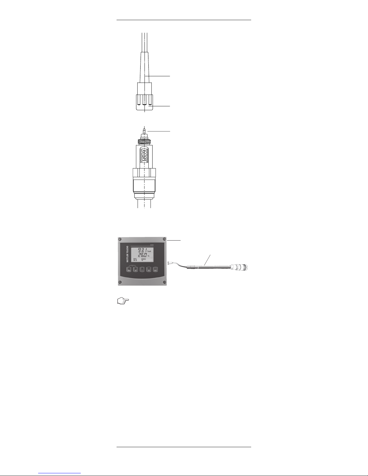
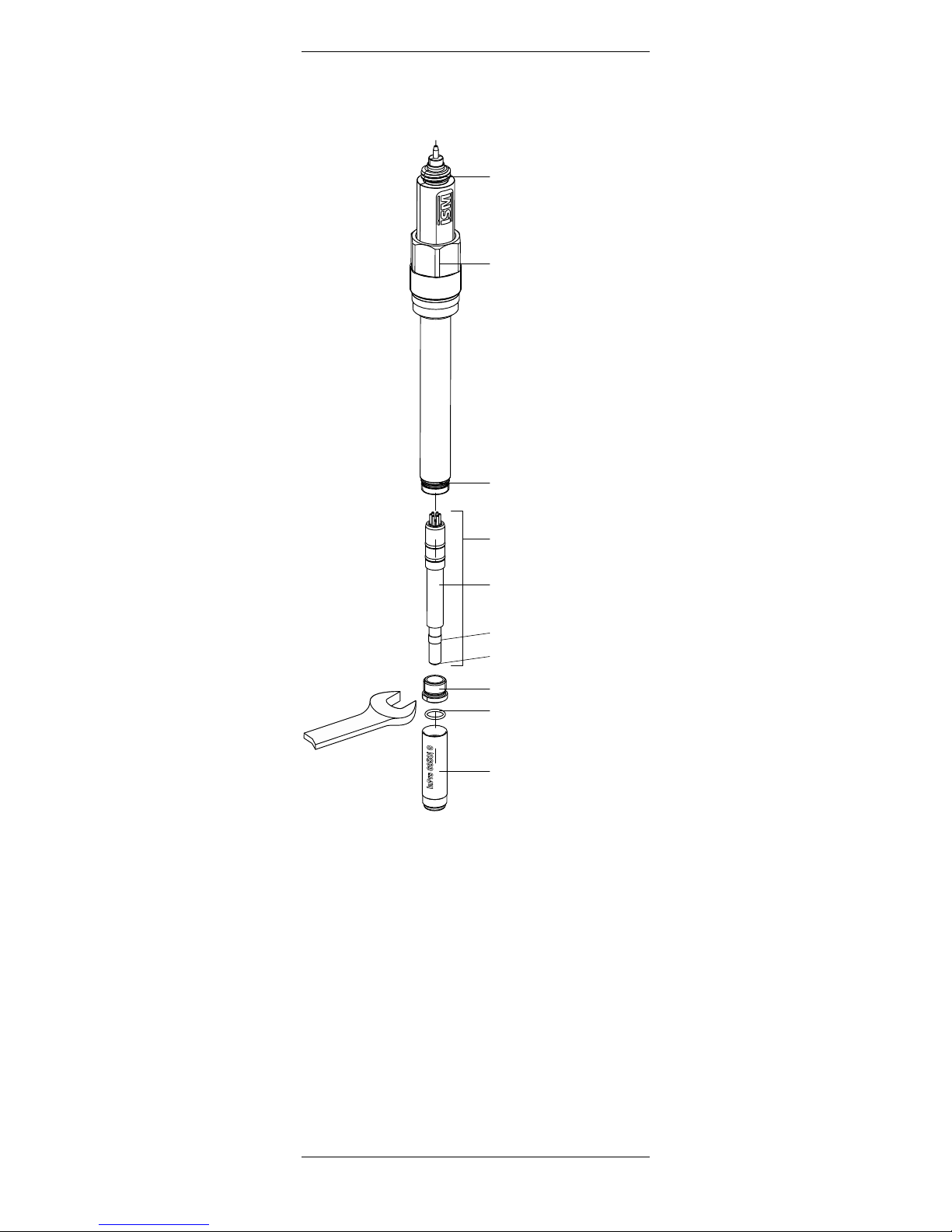
3.5 Equipment features
12 mm sensor
METTLER TOLEDO ISM O
2
sensors are supplied with
fitted membrane body but without electrolyte
and covered with the protection cap and have been
checked for proper function.
Anode (Pt)
Cathode and Guard Ring
Protection Cap
Cap Sleeve (N-type)
O-ring (silicone FDA/USP VI)
Membrane Body
Retainer Nut
Reference (Ag/AgCl)
Interior Body
O-ring
(9.0 3 1.0 mm, silicone FDA/USP VI)
Pg 13.5 Threaded Sleeve
AK9 Connector
16 InPro 6800G/6850iG/6900iG/6950i GO212 mm
InPro 6000 G – Series © 12 / 15 Mettler-Toledo GmbH
52 206 477 Printed in Switzerland
4
Installation
4
.1 Mounting the sensor
Important! Remove the protection cap before
mount ing the sensor.
Mounting the sensor in a housing
Please refer to the instruction manual of your housing
explaining on how to mount the sensor in place.
Mounting the sensor directly on a pipe or a vessel
The 12 mm sensors can be mounted directly through
a socket with inside thread Pg 13.5 and securely
tightened via the Pg 13.5 threaded sleeve.
4.2 Connection
4.2.1 Connecting the sensor to a AK9 cable
Note: The sensor is connected to the transmitter via
a AK9 cable. The AK9 cable ensures a secure connection between the transmitter and the sensor under
harsh industrial conditions. The robust watertight
IP68 connector housing guarantees maximum
process safety.
Do not touch the sensor at the AK9 connector plug!
Tightly screw the plug to fasten the two parts.
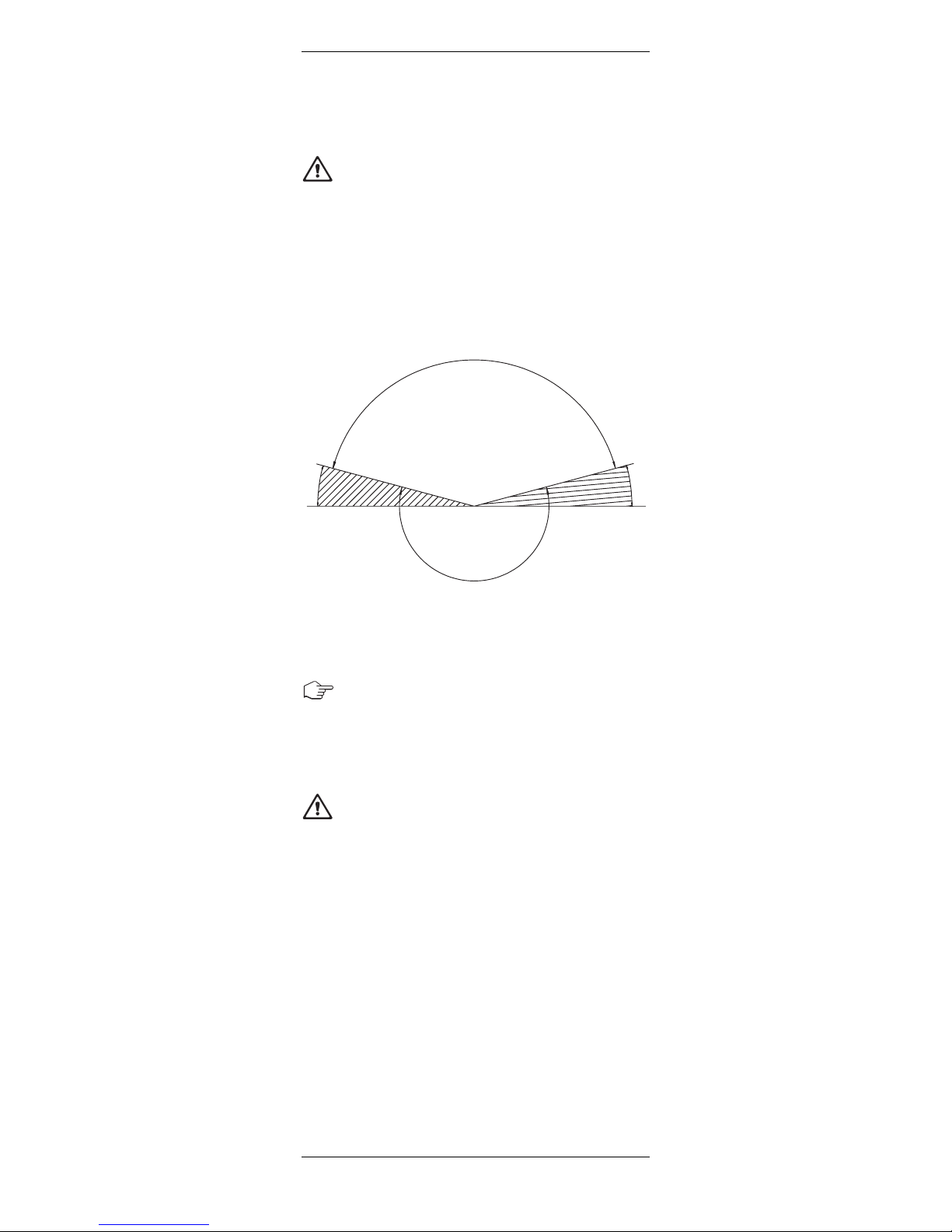
Admissible mounting position
Zulässige Einbaulage
Positionement de montage admis
I
nadmissible angle
Unzulässiger Winkel
Angle non admissible
52910094ME
15° 15°
InPro 6800G/6850i G/6900i G/6950i G O212 mm 17
© 12 /15 Mettler-Toledo GmbH InPro 6000 G – Series
Printed in Switzerland 52 206 477
4.2.2 Connecting the cable to the transmitter
Note: For connecting the AK9 or VP cable to the ter-
minals of the transmitter, please refer to the instructions given in the METTLER TOLEDO transmitter manual.
AK9 Connector
Plug
AK9 Cable for
Standard Use
O2 Transmitter
AK9 Cable or VP
18 InPro 6800G/6850iG/6900iG/6950i GO212 mm
InPro 6000 G – Series © 12 / 15 Mettler-Toledo GmbH
52 206 477 Printed in Switzerland
5
Operation
Important! Before using the sensors for the first time,
the electrolyte must be filled in (see “Chapter 6.2”).
5.1 Start-up and polarizing
Important! The protection cap must be removed be-
fore mounting the sensor in the process.
When the system is operated for the first time or if the
sensor has been disconnected from the voltage
source (transmitter or O2Sensor Master) for longer
than 5 min utes, the sensor has to be polarized
prior to calibration by connecting it to the operating
O2transmitter or to a sensor master. After 6 hours,
the sensor is fully polarized and ready for
operation.
Attention: The InPro 6950i G should never be polarized at air!
During Polarization, we suggest to use the protection
cap filled with cleaning and conditioning solution always (Chapter 7: Storage).
A shorter polarization period is sufficient if the sensor
has been disconnected for only a few minutes. The
following table serves to establish the correct polarization time in relation to the depolarization time.
Important! Setting of the polarization voltage on the
transmitter for correct measurements:
– Standard applications InPro 6800 G / 6850iG:
– 675 mV
– Measurement of permanently low oxygen concen-
trations (<500 ppb in liquids or <10,000 ppm
[vol.] in gases) in the presence of volatile acidic
Depolarization time1 Minimum required
t
depol
[Min.] polarization time2 [Min.]
t
depol
> 30 360
30 > t
depol
> 15 6 3 t
depol
15 > t
depol
> 5 4 3 t
depol
t
depol
< 5 2 3 t
depol
1 Depolarization time: Time span in which the pola rization voltage is cut off from the sensor. This is
the case:
– during the time the cable is disconnected or no
transmitter or sensor master is connected
to the cable, or the transmitter has been
disconnected from the current supply.
– after changing the electrolyte or membrane
body. In this case at least 6 houres of polariza tion must follow.
2 Polarization time: Time span during which the
sensor is under a polarization voltage.

InPro 6800G/6850i G/6900i G/6950i G O212 mm 19
© 12 /15 Mettler-Toledo GmbH InPro 6000 G – Series
Printed in Switzerland 52 206 477
components (e.g. carbon dioxide during measurements in breweries) e.g. InPro 6900iG/6950i G:
– 500 mV
Note: To ensure the supply of the correct polari za tion
voltage the transmitter must be set according to the
transmitter manual.
5.2 Calibration
5.2.1 Purpose of calibration
Each oxygen sensor has its own individual slope and
own individual zero point. Both values are subject
to change, for example, through electrolyte consumption or after exchange of electrolyte or membrane
body. To ensure high measurement accuracy of
the sensor, a calibration must be carried out regularly, but at least after each change of electrolyte or
membrane. Prior to calibration, the sensor has to be
polarized for at least 6 hours.
Important: Please remove the protection cap from
the sensor, rinse the sensor with water and dry it
wait at least 10 minutes before starting calibration. Store sensor upright with membrane pointing
down.
Note: To check if your sensor needs a recalibration, you may dry it and take it in the air to check
that the reading is close to 100 %. If not, then the
sensor needs a new calibration.
With ISM sensors all calibration data are stored in the
sensor.
5.2.2 What you have to know for calibration
General remarks:
– For calibration in gas (e.g. air), the sensor
membrane must be dry outside, since adhering
water drops can falsify the measured oxygen value.
– Make sure that the oxygen saturation index of
the calibration medium is correct and remains
constant during calibration.
– For correct calibration, a minimum flow rate of the
calibration medium is necessary.
– Make sure that all other parameters, such as
temperature and pressure, are constant.
For continuous applications, we recommend periodic
recalibration in line with your requirements on
accuracy, the type of process in operation and
your own experience. The frequency of the need for
re calibration depends very much on the specific
application, and therefore appropriate intervals cannot be exactly defined here.

20 InPro 6800G/6850iG/6900iG/6950i GO212 mm
InPro 6000 G – Series © 12 / 15 Mettler-Toledo GmbH
52 206 477 Printed in Switzerland
5.2.3 Single point calibration
For applications measuring more than 1% Vol. O
2
gas a single point calibration is recommended. In
this case the zero point is set manually to 0 nA. For
measuring below 1% Vol. O2a zero point calibration
with e.g. nitrogen gas is recommended.
B
y carrying out a single point calibration, the slope
o
r offset of the sensor can be set. The calibration
m
edium can be gas with known water-vapor satura-
t
ion (e.g. water-vapor saturated air).
After the sensor signal has stabilized, the complete
meas uring system can be calibrated to the100%
value of the desired measurable variable, e.g.100%
air, 20.95% O
2
, or 8.26 ppm at 25°C (77 °F) and
normal pressure (see instruction manual of the
transmitter).
Zero-point calibration is recommended for the InPro
6950iG only when measuring less than 125 ppm
(by vol. O
2
) in gases.
Attention! Incorrect zero point calibration is a
frequent source for measurement error. For correct
calibration, we recommend the use of carbon
dioxide gas with a level of purity of at least
99.9995 % for measurements in CO
2
applications.
For all other applications we recommend to use nitrogen (N2) gas.
After the sensor signal has stabilized (after 6…12
hours), the sensor can be calibrated through the
transmitter to zero% value of the desired measurable
variable, e.g. 0% air, 0.0% O2, or 0.0ppm (see instruction manual for the transmitter).
5.2.4 Dual point calibration
By carrying out a dual point calibration both slope
and zero point of the sensor can be set.
Important! In case of a dual point calibration,
always start with the zero point calibration before
calibrating the slope.

InPro 6800G/6850i G/6900i G/6950i G O212 mm 21
© 12 /15 Mettler-Toledo GmbH InPro 6000 G – Series
Printed in Switzerland 52 206 477
6
Maintenance
6
.1 Inspection of the sensor
6.1.1 Visual inspection
To check your sensor, we recommend the following
procedure:
– The contacts of the connector must be dry.
Moisture, corrosion and dirt in the connector can
lead to false readings.
– Check the cable for buckling, brittle areas or
ruptures.
– Before calibration always examine the membrane
foil for signs of damage. The foil must
be intact and clean. Dirty membranes should be
wip ed clean using a soft, moist tissue.
Note: An undulated membrane has no influence
on the sensor performance, assuming the membrane is intact.
– The membrane body must be replaced if the
sensor has too long a response time, the reading
is unstable or subject to drift, and if the sensor
cannot be calibrated or the membrane shows sign
of mechanical damage.
– Check the cathode area for discoloration, conta -
mination or cracks in the glass. If necessary rinse
with demineralized water and clean with a clean
soft brush or soft paper tissue.
Attention! Do not use any cleaning agents contai ning alcohol. This could damage the sensor or lead
to fault current.
Attention! The glass body is fragile and sensitive to
vibration.
22 InPro 6800G/6850iG/6900iG/6950i GO212 mm
InPro 6000 G – Series © 12 / 15 Mettler-Toledo GmbH
52 206 477 Printed in Switzerland
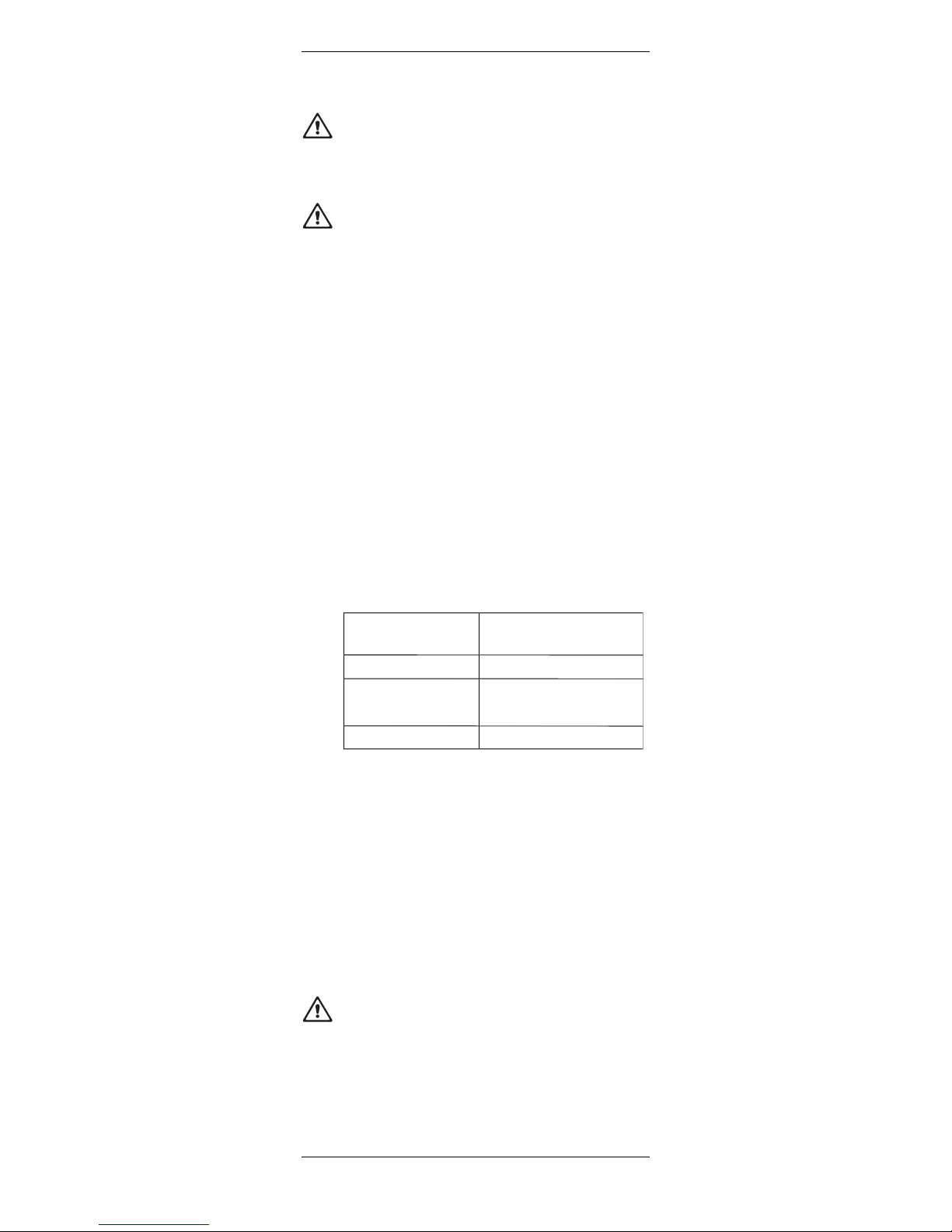
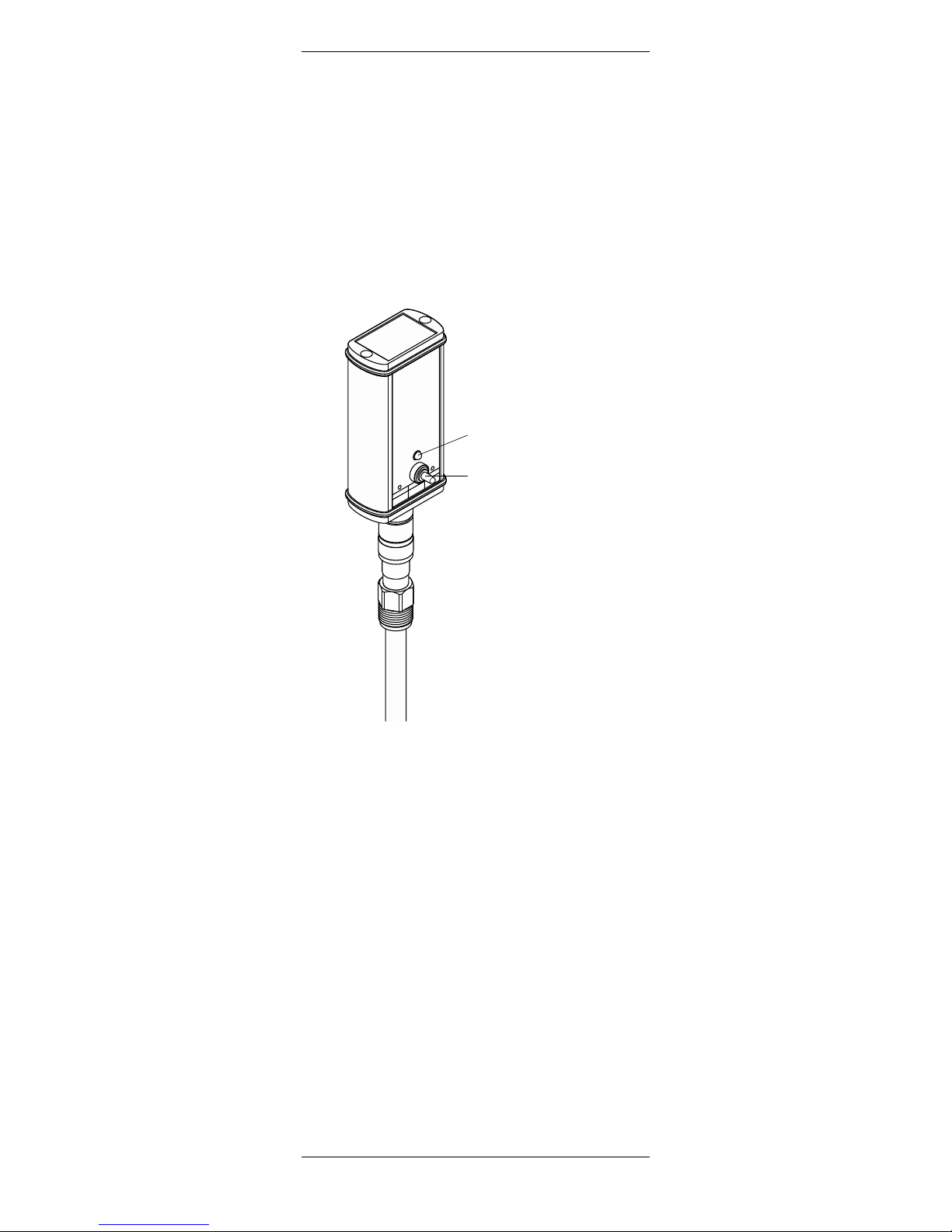
6.1.2 Using the METTLER TOLEDO O2sensor master
We recommend to use the METTLER TOLEDO
O2 sensor master to check the status of your sensor
as follows:
•
Connect the sensor to the O
2
s
ensor master.
The figure shows the Sensor Master (Order No. 52
200 892) for the analog sensor InPro 6800 G. For
the digital ISM sensors use the Sensor Master digital
ISM with order no. 52 206 329. For the digital Sensor Master the procedure is similar.
As soon as the sensor is connected to the O
2
sensor master, the polarization function is
automatically activated. Please note: if the
sensor was disconnected from the transmitter
for longer than 5 minutes, the sensor must be
polarized first (pola rizing time see “Section 5.1”)
to get representative test results.
• Battery Check:
Push the switch to the left. If the battery is ok and
the O
2
sensor master is operational the green LED
lights up. Otherwise, please consult the instruction
manual of the O2sensor master.
• Sensor Check:
For this test the O
2
sensor must be fully polarized
and the membrane of the sensor tip must be dry
and clean outside.
M
E
T
T
L
E
R
T
O
L
E
D
O
O
2
S
e
n
s
o
r
-
M
a
s
t
e
r
I
n
P
r
o
6
9
0
0
O
r
d
e
r
N
o
.
5
2
2
0
0
8
9
3
T
h
e
p
o
l
a
r
i
z
a
t
i
o
n
f
u
n
c
t
i
o
n
w
i
l
l
b
e
a
c
t
i
v
a
t
e
d
a
u
t
o
m
a
t
i
c
a
l
l
y
,
w
h
e
n
a
s
e
n
s
o
r
i
s
c
o
n
n
e
c
t
e
d
.
A
f
t
e
r
t
h
e
s
e
n
s
o
r
p
o
l
a
r
i
z
a
t
i
o
n
y
o
u
s
h
o
u
l
d
c
h
e
c
k
t
h
e
f
u
n
c
t
i
o
n
s
o
f
t
h
e
s
e
n
s
o
r
a
s
f
o
l
l
o
w
i
n
g
:
1
.
B
a
t
t
e
r
y
C
h
e
c
k
2
.
S
e
n
s
o
r
C
h
e
c
k
G
r
e
e
n
l
i
g
h
t
=
o
k
le
f
t
B
a
t
t
e
r
y
C
h
e
c
k
m
id
d
l
e
A
u
t
o
m
.
P
o
l
a
r
i
z
.
r
ig
h
t
S
e
n
s
o
r
C
h
e
c
k
1
2
Switch
LED

InPro 6800G/6850i G/6900i G/6950i G O212 mm 23
© 12 /15 Mettler-Toledo GmbH InPro 6000 G – Series
Printed in Switzerland 52 206 477
Expose the sensor (connected to O2sensor master) to
air. By pushing the switch to the right to position
“Sensor check”, the O2sensor master checks
whether the electrode current for air measurement is
within the specified range, i.e. 2500 to 6000 nA for
InPro 6950iG.
Air current Zero current in %
of the air current
6800 G 50– 110 nA <0.1
6850iG 50– 110 nA <0.1
6900iG 250– 500 nA <0.03
6950iG 2500– 6000 nA <0.025
If the green LED lights up the current for air
measurement is with in the specified range.
If the LED does not light up, you should check the
battery of the O2sensor master (see instruction manual “Accessories”). If the battery is working, than
there is probably a problem with your sensor. You
should change the electrolyte and/or the membrane
body of your sensor. If after a membrane change the
LED still does not light up, this means that there is
something wrong with the interior body of the sensor.
You should then change it (see “Section 6.2”).
Important! The Sensor Check function only verifies
the correctness of the electrode current for air
measurement. In order to be absolutely sure of the
functionality of the sensor, the residual signal in an
oxygen free medium should also be controlled (see
“Section 6.1.3”).
6.1.3 Testing the sensor via a transmitter
A periodic zero current measurement (no zero point
calibration!) is recommended for verification of prop-
er sensor function.
Note: At the time you carry out the zero current
measurement, the sensor must be polarized.
Zero current measurement can be done by using
zero ing gel (order no. 30 300 435) or nitrogen (N2)
or carbon dioxide (CO2) calibration gases with a
purity of at least 99.995%, alternatively in a sample
medium saturated with one of these gases.
After 2 minutes in an oxygen-free sample medium,
the reading on the transmitter should drop to
below 10% of the reading in ambient air, and
within 10 minutes the value should have dropped
to below 1 %.
If the measured values are too high, this suggests a
depleted electrolyte or a defective membrane. In the
first instance replace the electrolyte, and in the second case exchange both the membrane body and the
electrolyte accordingly.

24 InPro 6800G/6850iG/6900iG/6950i GO212 mm
InPro 6000 G – Series © 12 / 15 Mettler-Toledo GmbH
52 206 477 Printed in Switzerland
If after such procedures the above mentioned values
are still not reached, replace the interior body. If this
does not solve the problem send the sensor to your
local METTLER TOLEDO representative for inspection.
6.1.4 ISM design
T
he integrated ISM function allows an advanced moni-
t
oring of the sensor. The following parameters are
s
tored in the sensor:
– serial no.
– type of sensor
– order no.
– calibration data
– enhanced diagnostic data
– slope
– zero point
After powering up of the sensor the following automatic test procedures are running:
– dgital communication
– plausibility of the stored calibration data

InPro 6800G/6850i G/6900i G/6950i G O212 mm 25
© 12 /15 Mettler-Toledo GmbH InPro 6000 G – Series
Printed in Switzerland 52 206 477
6.2 Changing the electrolyte, the membrane body
o
r the interior body
Note: The InPro 6900iG and 6950iG use a special
electrolyte. This electrolyte ensures fast response time
and together with the guard ring increases the signal
stability of the sensor. The electrolyte must be exchanged on a regular basis or when the sensor has
been exposed to air for more than 24 hours without a
watering cap filled with conditioning solution.
If the membrane and/or the interior body exhibits
signs of failure (long response time, increased current in an oxygen-free medium, mechanical damage,
etc.) the membrane body and/or the interior body
has to be replaced.
Warning! The O
2
electrolyte has a slight alkaline pH
value. Contact of electrolyte with mucous membrane
or eyes is to be avoided. Therefore protective
gloves and safety glasses have to be worn for the
following dismantling works.
If such contact occurs, the affected area should be
well rinsed with water. In the case of accident, or
should ever any adverse signs appear, get immediate medical attention.
When changing the electrolyte, the membrane body
or the interior body, please observe the following
instructions (see also the following illustration):
Attention! Make sure that this maintenance step is
carried out in clean place.
1. Unscrew the cap sleeve from the sensor shaft
and carefully pull it off the sensor.
2. Pull off the membrane body from the interior
body. If it is tight-fitted, eject by pushing it with
the flat finger tip. Before electrolyte is refilled, the
membrane body must be removed from the cap
sleeve!
3. Rinse the interior body with demineralized water
and carefully dab it dry with a paper tissue.
Note: steps 4 to 7 may only be carried out
when changing the interior body.
4. Unscrew the retainer nut of the interior body with
an adjustable wrench or with a 9 mm wrench.
5. Remove the interior body by pulling it out of the
sensor shaft. If necessary use a plier.
Warning! Do not twist the interior body. Other -
wise the connection pins can be damaged.
6. Insert the new interior body in the sensor shaft.
Turn the interior body in the shaft until the slit of
the interior body is aligned with the pin placed in
the shaft.
26 InPro 6800G/6850iG/6900iG/6950i GO212 mm
InPro 6000 G – Series © 12 / 15 Mettler-Toledo GmbH
52 206 477 Printed in Switzerland
7. Press the body in the shaft and screw the new
retainer nut in place. Only hand tighten the retainer nut using a small wrench. Applying a too
high torque (>2 Nm) may damage the sensor.
8. Examine the O-rings visually for mechanical
defects, and replace if necessary.
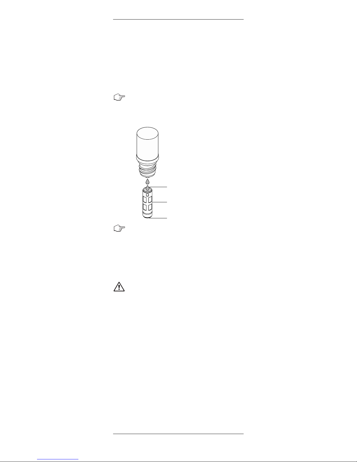
9. Half-fill the new membrane body with O
2
electrolyte.
Note: The electrolyte bottle is equipped with a
special pouring system. To ensure proper
functioning, hold the bottle vertically, upsidedown.
Note: make sure that all air bubbles are removed
from the membrane body. Air bubbles can be
removed by carefully tapping on the membrane
body.
10. Slip the membrane body over the interior body
while holding the sensor in a vertical position.
The excess electrolyte will be displaced and have
to be removed with a paper tissue.
Important! No electrolyte, sample media or
contamination may be present between the
membrane body and the cap sleeve. Please
check carefully!
11. Carefully slip the cap sleeve over the fitted
membrane body, holding the sensor in a vertical
position and screw it tight. The cap sleeve must
be clean and dry.
12. After each exchange of electrolyte or membrane
body, the sensor has to be repolarized and
re calibrated before it is ready for use.
1
⁄
2
1
⁄
2
O2 Electrolyte
Air
InPro 6800G/6850i G/6900i G/6950i G O212 mm 27
© 12 /15 Mettler-Toledo GmbH InPro 6000 G – Series
Printed in Switzerland 52 206 477
Replacement of the interior body
Anode (Pt)
Cathode and Guard Ring
O-ring
(silicone FDA/USP VI)
Membrane Body
Retainer Nut
Reference (Ag/AgCl)
Interior Body
O-ring
(9.0 3 1.0 mm,
silicone FDA/USP VI)
P
g 13.5 Threaded Sleeve
A
K9 Connector

28 InPro 6800G/6850iG/6900iG/6950i GO212 mm
InPro 6000 G – Series © 12 / 15 Mettler-Toledo GmbH
52 206 477 Printed in Switzerland
7
Storage
When the sensor is stored without polarization for
more than one week, the electrolyte has to be removed.
Always use clean water to clean the sensor membrane from outside.
Important: Never use alcohol or isopropanol or
mixtures with these organic solvents.
P
repare the cleaning and conditioning solution as
follows: Dissolve one tablet in 40 ml of deionized
water and wait 5 minutes for the tablet to be completely dissolved. Fill the protection cap with this solution and place it over the tip of the sensor. This solution has some cleaning properties which will keep
the membrane free of microorganisms. In case you
do not have any cleaning and conditioning set, you
may also use checking gel or deaerated water in the
protection cap. Before mounting the sensor in the
process, always remove the protection cap and rinse
the tip of the sensor with water.
Attention! If the storage period of the sensor without current supply (transmitter, sensor master) exceeds 1 week, the sensor should be stored dry, i.e.
without any electrolyte in the membrane body. A sensor being stored dry (without electrolyte in the
membrane body) may on no account be connected
to the O
2
sensor master or any other polarization
module.

InPro 6800G/6850i G/6900i G/6950i G O212 mm 29
© 12 /15 Mettler-Toledo GmbH InPro 6000 G – Series
Printed in Switzerland 52 206 477
8
Product specification
8
.1 Certificates
Each sensor is delivered with a set of 3.1 certificates (complying with EN10204).
All wetted metal parts (sensor shaft, cap sleeve and
membrane body) are identified with a engraved
symbol corresponding to the heat number on the
paper certificate delivered with the sensor.
Each wetted metal part (sensor shaft, cap sleeve and
membrane body) is polished in order to get a surface
roughness lower than 0.4 µm (16 µin). This represents a roughness grade number of N5 (according to
ISO 1320:1992).

30 InPro 6800G/6850iG/6900iG/6950i GO212 mm
InPro 6000 G – Series © 12 / 15 Mettler-Toledo GmbH
52 206 477 Printed in Switzerland
8.2 Specifications
InPro 6800 G/6850i G/6900i G/6950i G
Measurement principle Polarographic Clark electrode
Working conditions
Pressure resistance 6800 G: 0.2…9 bar
(measurement) 6850iG: 0.2…9 bar
6900i G: 0.2…9 bar
6950i G: 0.2…9 bar
Mechanical pressure resistance Max. 12 bar
Temperature limits –5…121°C
(mechanical) [23 …250 °F]
Operating temperature limits 6800 G: 0 … 70 °C
(ambient) [32 …158 °F]
6850i G: 0…70°C
[32…158°F]
6900i G: 0…70°C
[32…158°F]
6950i G: 0…40°C
[32…104°F]
(sterilizable)
Specification
Temperature compensation Automatic
Cable connection AK9
O-ring material Silicone, FDA and
USP Class VI approved
Kalrez
Membrane material PTFE/ Silicone/ PTFE
(reinforced with steel mesh)
Kalrez
Material sensor body 316L stainless steel
(wetted parts)
Surface roughness of N5 (R
a
= 0.4 µm [16µin])
wetted metal parts
Quick disconnect interior body Standard
Cathode Pt
Anode 6800 G: Ag
6850i G: Pt
6900i G: Ag
6950i G: Pt
Guard ring 6800 G: –
6850i G: –
6900i G: Pt
6950i G: Pt
Reference Ag
Dimensions
Sensor diameter
6800 G: 12 mm
6850i G: 12 mm
6900i G: 12 mm
6950i G: 12 mm
Immersion length (a) 120, 220 mm
for 12 mm sensor [4.7, 8.66"]
Performance
Measurement range in O
2
Gas 6800 G: 300 ppm to100% (1 bar)
6850iG: 300 ppm to 100% (1 bar)
6900iG: 50 ppm to100% (1 bar)
6950iG: 5 ppm to 20% (1 bar)
Accuracy 6800 G: ± [1 % + 300 ppm]
6850i G: ± [1% + 300 ppm]
6900i G: ± [1% + 50 ppm]
6950i G: ± [1% + 5 ppm]
Response time 90 % of final value in <30 s
at 25°C/77°F
Sensor signal for ambient air 6800 G: 50…110 nA
at 25°C/77°F 6850iG: 50 …110 nA
6900iG: 250...500 nA
6950iG: 2500... 6000 nA
Residual signal 6800 G <0.1 % of the signal
in oxygen-free medium 6850iG: <0.1 % of the signal
6900i G: <0.03% of the signal
6950i G: <0.025% of the signal
 Loading...