

Mettler Toledo InPro 5000 Instruction Manual
InPro®5000 CO2Sensors
Instruction manual
Bedienungsanleitung
Instructions d’utilisation
InPro5000
52 002 465

English Page 3
Deutsch Seite 21
Français Page 59
2
InPro5000 CO
2
S
ensor 12 mm
InPro5000 © 09/06 Mettler-Toledo AG
52 002 465 Printed in Switzerland

InPro®5000 CO2Sensors
Instruction manual
I
nPro5000 CO
2
S
ensor 12 mm 3
© 09/06 Mettler-Toledo AG InPro5000
Printed in Switzerland 52 002 465

Table of Contents
Page
1
Introduction .......................................................5
2
Important notes .................................................6
2.1 Notes on operating instructions .............................6
2.2 Intended use .......................................................6
2.3 Safety instructions ...............................................7
3 Product description ............................................8
3.1 General information .............................................8
3.2 Principles of CO2measurement.............................8
3.3 Scope of delivery .................................................8
3.4 Equipment features ..............................................9
4 Preparation......................................................10
4.1 Start-up ............................................................10
4.2 Calibration of the pH electrode ............................11
4.2.1 Connecting the InPro5000 sensor to a VP cable ...11
4.2.2 Connecting the VP cable to transmitter 5100e ......12
4.2.3 Calibration of pH electrode/transmitter 5100e.......12
4.3 Mounting the membrane body ............................13
4.4 Mounting the sensor ..........................................14
4.5 Sterilization.......................................................14
5 Operation.........................................................15
5.1 Calibration of the CO2sensor ..............................15
6 Maintenance....................................................16
6.1 Inspection ........................................................16
6.1.1 Visual inspection ...............................................16
6.1.2 Checking wiring and transmitter with the
pH simulator.....................................................16
6.2 Changing the CO2electrolyte and
membrane body................................................17
6.3 Maintenance of the pH electrode..........................17
6.4 pH electrode replacement ...................................17
7
Storage
............................................................17
8 Product specification ........................................18
8.1 Certificates........................................................18
8.2
Specifi
cations
....................................................
18
9 Ordering information ........................................19
9.1 Sensors............................................................19
9.2 Accessories ......................................................19
9.3
Spare parts
.......................................................19
9.4 Transmitter .......................................................19
4
InPro5000 CO
2
S
ensor 12 mm
InPro5000 © 09/06 Mettler-Toledo AG
52 002 465 Printed in Switzerland

I
nPro5000 CO
2
S
ensor 12 mm 5
© 09/06 Mettler-Toledo AG InPro5000
Printed in Switzerland 52 002 465
1 Introduction
Thank you for buying the InPro5000 sensor from
METTLER TOLEDO.
The construction of the InPro 5000 sensor employs
leading edge technology and complies with safety
regulations currently in force. Notwithstanding this,
improper use could lead to hazards for the user or
a third-party, and /or adverse effects on the plant
or other equipment.
Therefore, the operating instructions must be read
and understood by the persons involved before work
is started with the sensor.
The instruction manual must always be stored close at
hand, in a place accessible to all people working with
the InPro 5000.
If you have questions, which are not or insufficiently
answered in this instruction manual, please contact
your METTLER TOLEDO supplier. They will be glad to
assist you.

6
InPro5000 CO
2
S
ensor 12 mm
InPro5000 © 09/06 Mettler-Toledo AG
52 002 465 Printed in Switzerland
2 Important notes
2.1 Notes on operating instructions
These operating instructions contain all the
information needed for safe and proper use of
the InPro5000 sensor.
The operating instructions are intended for personnel
e
ntrusted with the operation and maintenance of the
sensors. It is assumed that these persons are familiar
w
ith the equipment in which the sensor is installed.
Warning notices and symbols
This instruction manual identifies safety instructions
and additional information by means of the following
symbols:
This symbol draws attention to
safety instructions
and warnings of potential danger which, if neglected,
could result in injury to persons and/ or damage
to property.
This symbol identifies
additional information and
instructions which, if neglected, could lead to defects,
inefficient operation and possible loss of production.
2.2 Intended use
InPro5000 sensors are intended solely for in line
measurement of dissolved CO2(carbon dioxide), as
described in this instruction manual.
Any other use, or use not mentioned here, that is incompatible with the technical specifications is deemed
inappropriate. The operator is solely responsible for
any damage arising from such use.
Other prerequisites for appropriate use include:
– observing the instructions, notes and requirements
set out in this instruction manual.
– observing all local safety regulations concerning
safety on work.
– observing all information and warnings in the
documentation dealing with the products used
together with the sensor (housings, transmitters,
etc.).
–
observing all safety regulations governing
the equipment in which the sensor is installed.
– observing the prescribed inspection and mainte-
nance intervals.
– correct care and maintenance of the unit,
according to the instruction manual.
– observing the prescribed environmental and
operational conditions, and permitted installation
positions.

I
nPro5000 CO
2
S
ensor 12 mm 7
© 09/06 Mettler-Toledo AG InPro5000
Printed in Switzerland 52 002 465
2.3 Safety instructions
– The InPro5000 sensors should be installed,
o
perated, maintained only by personnel familiar
with the sensor and who are qualified for such
work.
–
A defective sensor must neither be installed nor put
into service.
– Only the maintenance work described in these
operating instructions may be performed on the
sensors.
– When changing faulty components, use only
original spare parts obtainable from your METTLER
TOLEDO supplier (see section 9).
– No modifications to the sensors and the
accessories are allowed. The manufacturer/
supplier accepts no responsibility for damage
caused by unauthorised modifications. The risk is
borne entirely by the user.

8
InPro5000 CO
2
S
ensor 12 mm
InPro5000 © 09/06 Mettler-Toledo AG
52 002 465 Printed in Switzerland
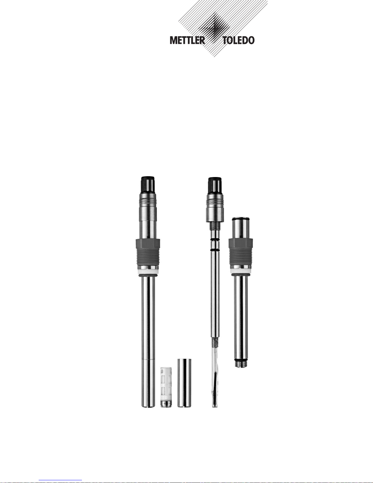
3 Product description
3.1 General information
The sensor InPro5000 with integrated temperature
probe is used for dissolved carbon dioxide measurem
ent.
T
he sensor has been designed for accurate and precise
measurement at low to medium carbon dioxide partial
pressure.
The sensor is
sterilizable and compatible with CIP
(
cleaning in place).
The sensor consists of an exchangeable pH electrode
which is built in a steel shaft and fixed with a small
hexagonal screw.
3.2 Principles of CO2measurement
Here is a short summary of the principle of the
potentiometric measurement of CO2which this
sensor is based (Severinghaus). The InPro5000 sensor employs a gas permeable silicone membrane
which is tightly stretched around a special engineered
flat pH membrane. The CO
2
gas from the sample or
process diffuses across the membrane until its partial
pressure equilibrates within the electrolyte film in front
of the pH sensitive glass and the bulk of the internal
electrolyte.
The dissolved CO2gas reacts with water to form
bicarbonate and H+ions:
The formed H+ions lead to a pH change of the inner
electrolyte which is measured with the integrated pH
electrode. Thus, the CO
2
partial pressure can be
calculated using the pH and the temperature, which is
detected as well.
3.3 Scope of delivery
Each sensor is supplied together with:
– 1 bottle CO2-electrolyte 25 ml
– 1 quality control certificate
– 1 inspection certificate 3.1
(in accordance with EN 10204.3/3.1)
Membrane body and cap sleeve are not mounted.
The interior body is protected against drying out with
a wetting cap, filled with CO
2
-electrolyte.
Please check completeness.
CO2+H2O HCO
3
–
+ H
+
I
nPro5000 CO
2
S
ensor 12 mm 9
© 09/06 Mettler-Toledo AG InPro5000
Printed in Switzerland 52 002 465
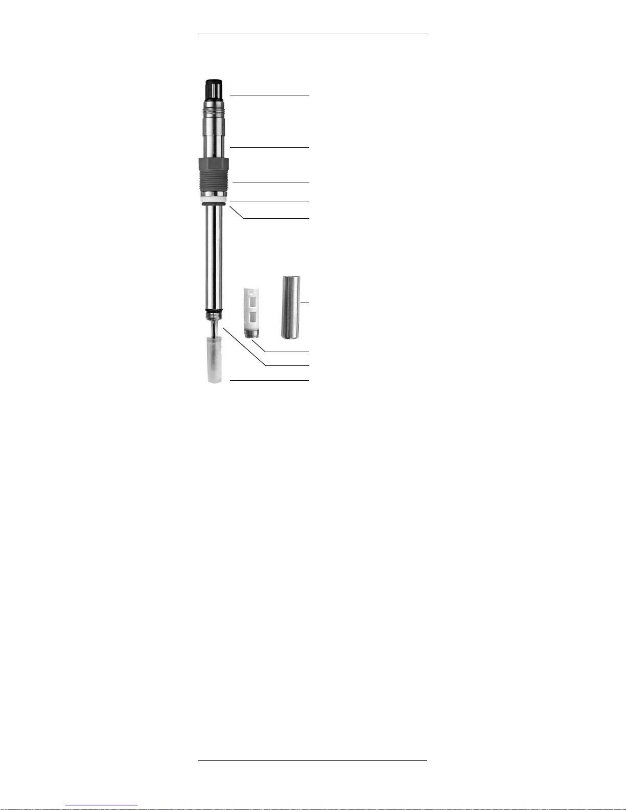
3.4 Equipment features
VP connector
O-ring (10.77 x 2.62 mm,
silicone FDA)
Pg 13.5 threaded sleeve
Washer PTFE
Cap sleeve
Membrane body
Wetting cap
Interior body (pH electrode)
H
exagonal screw
1
0 InPro5000 CO
2
S
ensor 12 mm
InPro5000 © 09/06 Mettler-Toledo AG
52 002 465 Printed in Switzerland
4 Preparation
4.1 Start-up
The interior body (pH electrode) is ready for calibration.
– On unpacking, check the pH electrode for
mechanical damage. Report any damage imme-
diately to your METTLER TOLEDO supplier.
– Remove the watering cap, cap sleeve, membrane
body and briefly rinse the sensor with de-ionized
water.
– After rinsing, the sensor should only be dapped dry
with a tissue. Do not rub the pH sensitive glass,
since this can lead to electrostatic charging and
sluggish response times.
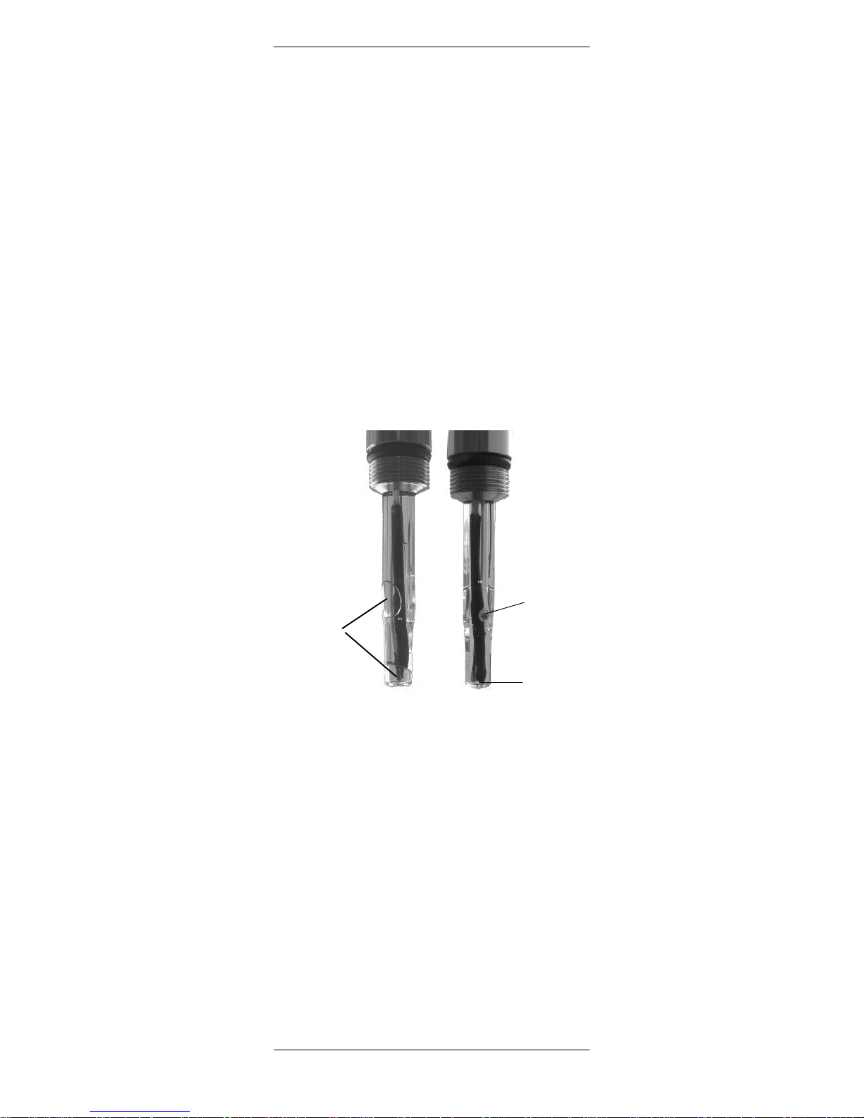
– Check inside the pH sensitive glass for the presence
of any air bubbles and remove same by gently
swinging in a vertical plane (shaking down as with
a thermometer).
Before using the sensor for the first time, make sure that
the interior body (pH electrode) is well fixed into the
steel body. The VP connector must not be rotated in the
shaft. If so, the inner part has to be fixed by tightening
the small
hexagonal screw below the connector.
Ceramic
diaphragm
pH sensitive
glass
Air
bubbles
A: pH electrode
with air bubbles:
will not work.
B: Correct pH electrode
with removed bubbles.
AB
I
nPro5000 CO
2
S
ensor 12 mm 11
© 09/06 Mettler-Toledo AG InPro5000
Printed in Switzerland 52 002 465
4.2 Calibration
Purpose of calibration: Each CO2sensor and Interior
b
ody (pH electrode) has its individual slope and zero
point.
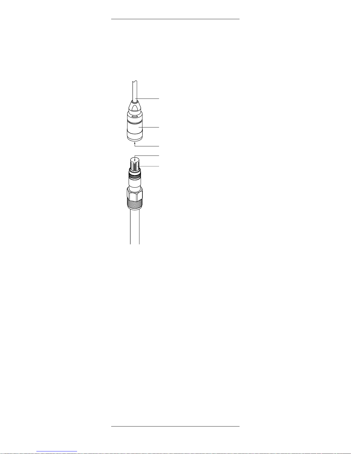
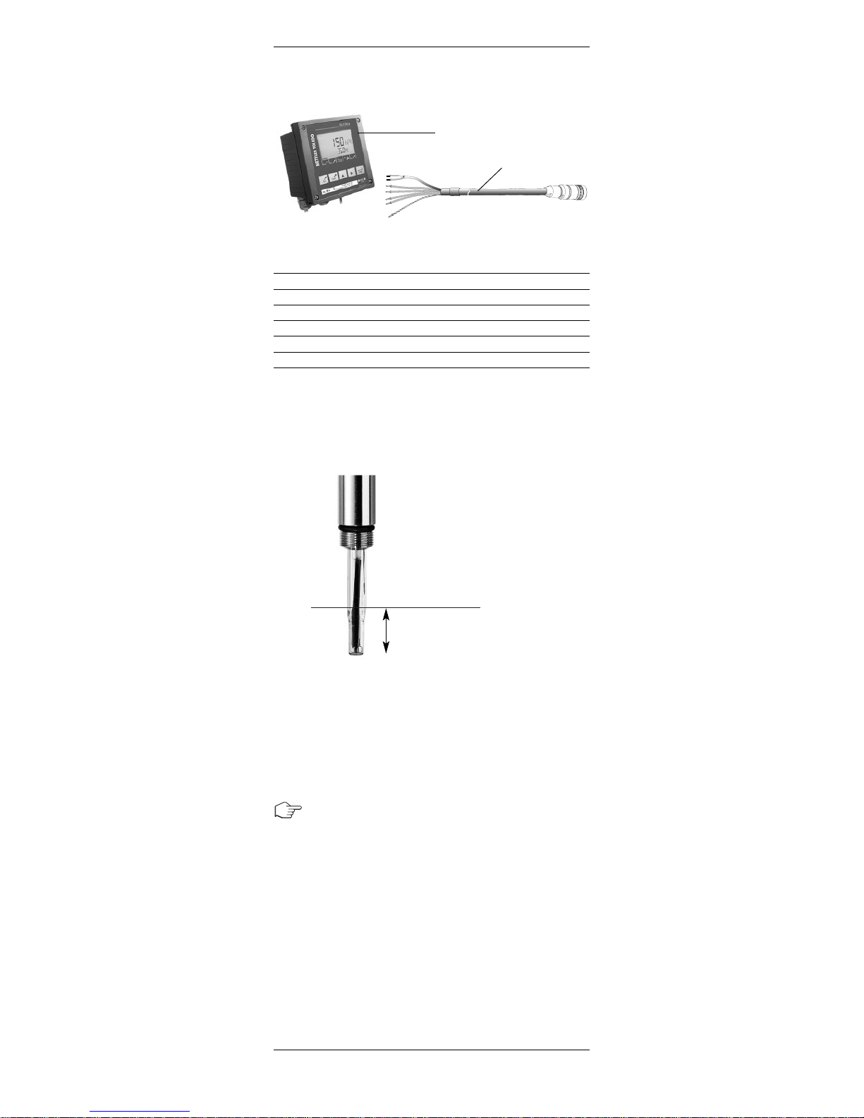
4.2.1 Connecting the InPro5000 to a VP cable
The sensor is connected to the transmitter 5100e via
a VP cable ensuring a secure connection under harsh
industrial conditions. The robust watertight IP68 connector housing guarantees maximum process safety.
To connect the VP cable to the sensor align the notch
of the VP connector with the key in the plug. Then tightly screw the plug to fasten the two parts.
VP cable
Plug
Pin
Notch
VP connector
1
2 InPro5000 CO
2
S
ensor 12 mm
InPro5000 © 09/06 Mettler-Toledo AG
52 002 465 Printed in Switzerland
4.2.2 Connecting the VP cable to the transmitter
Standard connection for CO2transmitter 5100e
Function VP cable wire Terminal connection
pH glass transparent 1
Reference red 2
Temperature 1 white E
Temperature 2 green D
Shielding green/yellow C
For further details check instruction manual of
the transmitter.
4.2.3 Calibation of pH electrode/transmitter 5100 e
Prepare electrode as described in section 4.1 “Startup”. We recommend a 2-point calibration in pH buffer
pH 7.00 and pH 9.21. Before calibration, first remove
wetting cap. Normally you start with buffer pH 7.00 for
determining zero point and then buffer pH 9.21
for determining the slope. Please refer to instruction
manual of the transmitter for further details.
Important settings: Temperature sensor select Pt1000.
VP Cable
CO
2
Transmitter
Min. immersion depth
,25 mm / 1"
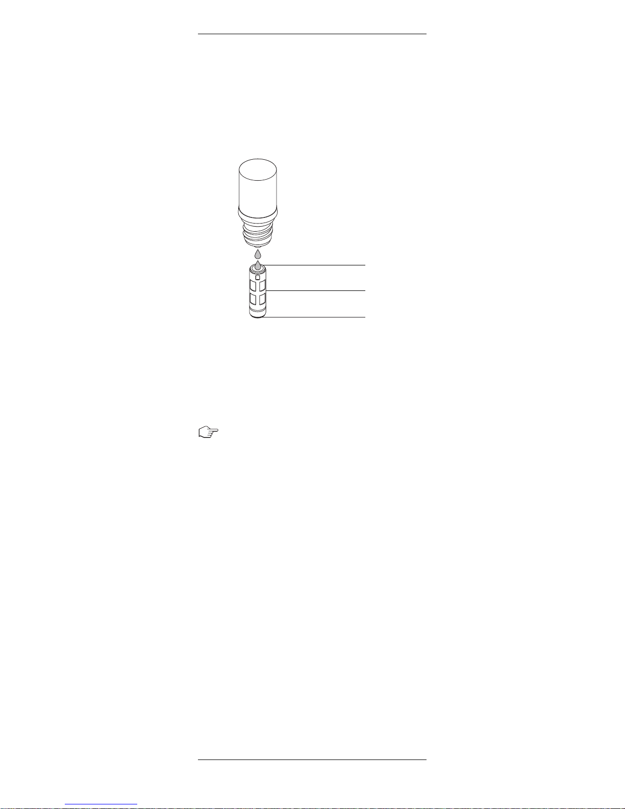
4.3 Mounting the membrane body
– After calibration of the pH electrode rinse the pH
electrode with de-ionized water and carefully dab
it with a paper tissue.
– Fill the new membrane body half way with CO
2
electrolyte.
Make sure that all air bubbles are removed from the
membrane body. Air bubbles can be removed by
carefully tapping on the membrane body.
– Slip the membrane body over the pH electrode
while holding the sensor in a vertical position.
The excess electrolyte will be displaced should
be wiped dry with a paper tissue.
Important: No electrolyte, sample media or
contamination may be present between the
membrane body and the cap sleeve. Please check
carefully.
– Carefully slip the cap sleeve over the fitted
membrane body, holding the sensor in a vertical
position and screw it tight. The cap sleeve must be
clean and tight.
I
nPro5000 CO
2
S
ensor 12 mm 13
© 09/06 Mettler-Toledo AG InPro5000
Printed in Switzerland 52 002 465
1
/
2
1
/
2
CO
2
electrolyte

1
4 InPro5000 CO
2
S
ensor 12 mm
InPro5000 © 09/06 Mettler-Toledo AG
52 002 465 Printed in Switzerland
4.4 Mounting the sensor
P
lease read carefully the instruction manual of the
particular housing (InFit761-... or InTrac797) for
correct sensor installation.
T
he InPro5000 sensor can be mounted directly on a
top plate of a small bioreactor or in a pipe with an
i
nside Pg 13.5 thread and securely tightened via the
Pg 13.5 threaded sleeve.
Remark: Mounting upside-down or horizontaly is not
possible due to internal pH electrode. An angle of 15°
or bigger to horizontal is needed.
4.5 Sterilization
The installed sensor will be sterilized together with the
bioreactor. The InPro5000 is in-situ sterilizable or in an
autoclave. After cooling down but before inoculation a
process calibration step, as described in chapter 5, is
needed to achieve accurate measurements.
Remark: For best accuracy please wait one hour after
cooling down before process calibration step according
chapter 5.1.

I
nPro5000 CO
2
S
ensor 12 mm 15
© 09/06 Mettler-Toledo AG InPro5000
Printed in Switzerland 52 002 465
5 Operation
5.1 Calibration of the CO2sensor
The InPro5000 sensor can be calibrated with CO
2
gas or a CO2/N2gas mixture. Example: If a CO
2
p
artial pressure of 150 mbar is expected, you can use
a
gas with 15% CO
2
/
85% N
2
i
n nitrogen to achieve
best results. The calibration can be made in a gas or
liquid phase. For calibration in a solution you have to
wait until an equilibrium is reached. Depending on the
p
H value of the solution a large amount of CO
2
w
ill
react to build bicarbonate ions before building-up a
constant partial pressure of CO2.
Recommendations:
• For small “benchtop” bioreactors the sensor can
be calibrated by flushing the empty or liquid
filled reactor with a CO
2
containing gas mixture.
• For larger bioreactors the gas consumption will be
too high,
therefore it is not recommended.
For larger bioreactors
the gas consumption would
be too high and therefore we recommend the
calibration with the aid of the retractable
housing InTrac797. Please operate the retractable
housing according the instruction manual
InTrac797 to ensure sterile operation. Additionally
the in- and outlet of the lower flushing chamber
must be equipped with sterile filters to avoid any
contamination with the calibration gas.
Calibration procedure:
• Sterilize CO2sensor InPro5000 in measuring
position (membrane inside bioreactor) together
with the bioreactor.
•
Sterilize lower and upper flushing chambers
of housing InTrac 797.
•
After cooling down retract sensor in maintenance
position (membrane in lower chamber).
• Flush lower chamber with sterile calibration gas.
The pressure inside the flushing chamber must be
known for proper calibration.
•
After calibration close in- and outlet of the
lower chamber and reinsert sensor in measuring
position. Sensor is now ready for measurement.

1
6 InPro5000 CO
2
S
ensor 12 mm
InPro5000 © 09/06 Mettler-Toledo AG
52 002 465 Printed in Switzerland
6 Maintenance
6.1 Inspection
6.1.1 Visual inspection
T
o check the sensor, we recommend the following pro-
c
edure:
•
The contacts of the VP connector must be dry.
Moisture, corrosion and dirt can lead to false readings.
• Check the cable for kinks, brittle areas or tears.
• Examine the membrane foil optically for signs of
damage. The foil must be intact and clean. Dirty
membranes should be wiped clean using a soft,
moist tissue.
Note: An undulated membrane has no influence on
the sensor performance, assuming the membrane
is intact.
•
The membrane body must be replaced if the sensor has a long response time, the reading is unstable or subject to excessive drift, and if the sensor cannot be calibrated with CO
2
gas or the
membrane shows sign of mechanical damage.
• Check the pH sensitive glass for cracks. The di-
aphragm should show a white color. If necessary
rinse with deionized water and clean carefully with
soft paper tissue.
Attention! Do not use any cleaning agents containing alcohol. This could damage the sensor or lead to
fault results.
Attention! The pH electrode is made of glass and
therefore fragile.
6.1.2 Checking wiring and transmitter
with the pH simulator
Necessary equipment:
pH simulator 112 (p/n 31 112 3003) and VP module
(p/n 52 120 939).
This equipment enables the testing of the VP cable
and correct wiring of the cable to the transmitter. Switch
the VP simulator to Pt1000 position. Additionally it is
possible to check the linearity, temperature compen
sation and quality of the input circuit (input resistance
and input current) of the CO2transmitter.

I
nPro5000 CO
2
S
ensor 12 mm 17
© 09/06 Mettler-Toledo AG InPro5000
Printed in Switzerland 52 002 465
6.2 Changing the CO2electrolyte
a
nd membrane body
W
e recommend to use a new membrane body after
each batch (see section 4.3). After each calibration of
the pH electrode (section 4.2) new CO2electrolyte
should be filled in the membrane body.
6.3 Maintenance of the interior body (pH electrode)
If the pH electrode shows a sluggish response
time and/ or insufficient sensitivity the pH sensitive
glass can be reactivated using a HF solution
(p/n 51 319 053). The pH sensitive glass part only
is immersed into this solution for 5
minutes, is then
immediately and thoroughly rinsed with deionized
water and then stored in 3 M KCl up to the diaphragm
for 12 hours. This procedure will make the electrode
faster but will limit the life time hardly.
6.4 Replacement of the interior body (pH electrode)
Typically after 10– 20 sterilization cycles the pH
electrode must be replaced. Please refer to the
instruction manual of the replacement interior body
InPro5000.
7 Storage
For storage we recommend to fill the membrane
body with fresh CO
2
electrolyte and rebuilt the
sensor together. The wetting cap, filled with water, will
prevent a drying-out of the membrane.
 Loading...