

Mettler Toledo InLab 605 O2-Sensor, InLab 605-ISM-Sensor General Instructions Manual
METTLER TOLEDO
InLab
®
605 O2-Sensor
InLab®605-ISM-Sensor
General instructions
Betriebsanleitung
Instructions générales
Istruzioni d’uso generali
Instrucciones generales
般的な手順
般指示
РРууккооввооддссттввоо
52201140_InLab_605_Buechlein.qxd:Layout 1 26.1.2009 8:44 Uhr Seite 1
2
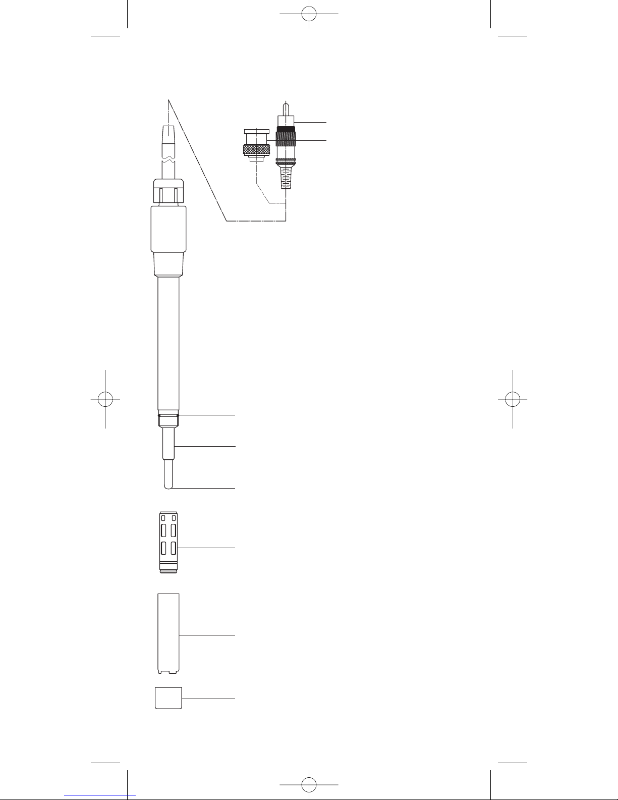
E
nglish:
1
) IP67 BNC Connector / Cinch
2) O-ring
3
) Anode (silver)
4) Cathode
5
) Membrane body
6
) Cap sleeve
7) Protection cap
Deutsch:
1) IP67 BNC Steckverbinder / Cinch
2) O-Ring
3
) Anode (Silber)
4
) Kathode
5) Membrankörper
6) Überwurfhülse
7) Schutzkappe
F
rançais:
1) Connecteur IP67 BNC / Cinch
2
) Joint torique
3) Anode (argent)
4) Cathode
5) Module à membrane
6) Gaine
7) Capuchon de protection
Italiano:
1) Connettori IP67 BNC / Cinch
2) O-ring
3) Anode (argento)
4) Catode
5) Corpo della membrana
6) Guaina
7) Cappuccio di proteczione
Español:
1) Conector IP67 BNC / Cinch
2) Junta tórica
3) Ánode (plata)
4) Cátode
5) Cuerpo de membrana
6) Manguito tapón
7) Cubierta protectora
日本語
1) IP67適合BNCコネクターCinch
2) Oリング
3) アノード(陽極、銀)
4) カソード(陰極)
5) メンブラン
6) キャップスリーブ
7) 保護キャップ
中文:
1) IP67 BNC/Cinch 接头
2) O形圈
3) 阳极(银)
4) 阴极
5) 溶解氧膜
6) 套管
7) 保护帽
РРууссссккиийй::
1) Разъем BNC/Cinch IP67
2) Резьбовое кольцо
3) Анод (серебро)
4) Катод
5) Мембранный модуль
6) Нижняя часть корпуса на резьбе.
7) Защитный колпачок
1
2
3
4
5
6
7
InLab®605 O2-Sensor
52201140_InLab_605_Buechlein.qxd:Layout 1 26.1.2009 8:44 Uhr Seite 2
3
Intelligent Sensor Management (ISM®)
The METTLER TOLEDO dual channel portable meters SevenGo Duo (pro) SG23, 68 and 78
have the ability to automatically recognize ISM sensors upon connection, transfer calibration data to and from the sensor etc. For more information regarding ISM
®
please read the
respective chapter of the operating instructions supplied with the meter.
Intelligent Sensor Management (ISM®)
D
ie tragbaren Zweikanal-Messgeräte SevenGo Duo (pro) SG23, 68 und 78 von METTLER
T
OLEDO erkennen die ISM-Sensoren automatisch beim Anschluss, übertragen Kalibrie-
r
ungsdaten auf den Sensor bzw. vom Sensor usw. Für weitere Informationen zu ISM
®
l
esen
Sie bitte den entsprechenden Abschnitt in der Betriebsanleitung des Messgerätes.
Intelligent Sensor Management (ISM®)
Les conductimètres portatifs à double canal SevenGo Duo (pro) SG23, 68 et 78 de
METTLER TOLEDO reconnaissent automatiquement les capteurs ISM dès leur connexion et
peuvent transférer les données de calibrage depuis et vers le capteur, etc. Pour plus d’informations sur la technologie ISM
®
, nous vous invitons à consulter le chapitre correspon-
dant dans la notice fournie avec le conductimètre.
ISM®(Intelligent Sensor Management)
I misuratori portatili a doppio canale METTLER TOLEDO SevenGo Duo (pro) SG23, 68 e 78
sono in grado di riconoscere automaticamente i sensori ISM al collegamento, di trasferire
i dati di taratura da e verso il sensore e altro ancora. Per ulteriori informazioni su ISM
®
,
consultare il rispettivo capitolo delle istruzioni operative fornite con il misuratore.
Intelligent Sensor Management (ISM®)
Los medidores portátiles de doble canal METTLER TOLEDO SevenGo Duo (pro) SG23, 68
y 78 tienen la capacidad de reconocer automáticamente los sensores ISM desde el
momento de la conexión, la transferencia de datos de calibrado desde el sensor y hacia
él, etc. Para obtener más información sobre ISM
®
, consulte el correspondiente capítulo de
las instrucciones de funcionamiento suministradas con el medidor.
インテリジェントセンサマネジメント(ISM®)
メトラー・トレド社の2チャンネルポータブルタイプ計測機器SevenGo Duo (pro) SG23,
68 及び 78は、接続されると自動的にISMセンサを認識し、また、測定値をセンサへ供給
したり、逆にセンサから受信したりすることが可能です。ISM
®
に付いての詳細は本体に添
付されている使用説明書の該当する章をご参照ください。
Intelligent Sensor Management (ISM™)
METTLER TOLEDO双通道便携式电导率仪SG23、68和78具有在连接后自动辨
识 ISM™电极的能力,能够从电极获得和向电极传输校准数据。有关ISM™的更
详细信
Intelligent Sensor Management (ISM®)
Двухканальные портативные измерители METTLER TOLEDO серии SevenGo Duo (pro)
SG23, 68 и 78 имеют возможность автоматического распознавания датчиков ISM®при их
подключении, передачи калибровочной информации датчику и от него и т. п. Более
подробную информацию о серии ISM®можно найти в соответствующем разделе инструкции
по эксплуатации, прилагаемой к измерителю.
Intelligent Sensor Management (ISM®)
52201140_InLab_605_Buechlein.qxd:Layout 1 26.1.2009 8:44 Uhr Seite 3

4
Instruction manual InLab®605 O2-Sensor
1 Product description
1.1 Utilization, conformity and identification
The InLab 605 is a polarographic oxygen sensor (Clark principle) designed for the simultaneous measurement of dissolved oxygen and temperature in water applications. The rob
ust IP67 connectors provide waterproof performance in outdoor or industrial applications.
T
he InLab 605 represents a state-of-the-art product and is built under the strict quality
g
uidelines for ISO 9001. The serial number is engraved on the sensor head for traceabil-
ity.
1
.2 Key data and characteristics
L
ength 120 mm
D
iameter 12 mm
Connectors IP67 BNC / Cinch
Temperature sensor NTC
Shaft material PPS, glass fiber reinforced
Membrane material Silicone / Teflon (reinforced with steel mesh)
O-Ring material Viton, Silicone
Temperature range 0...60 °C
Humidity 0...100% rel.
Media The sensor is designed for use in aqueous samples.
1.3 Equipment features and scope of delivery
The oxygen sensor is shipped with a silicone membrane body in place and filled with electrolyte, thus it is ready for use. The InLab 605 features a built-in temperature device (NTC)
that allows for automatic compensation of temperature changes.
2 Safety
Please read this instruction manual entirely before using the sensor.
3 Measuring dissolved oxygen
3.1 Initial start-up
For instructions concerning the connection of the IP67 cable to the instrument, please refer
to the instrument instruction manual.
Notice: The protective cap at the tip of the sensor should be removed before putting the sensor into operation. When the sensor is installed for the first time or has been disconnected
from the instrument for longer than 5 minutes, the sensor must be polarized before calibration or the first measurements. This can be achieved by connecting the sensor to the instrument for at least six hours. If the sensor has been disconnected for less than 5 minutes
a polarization time of 10 minutes suffices.
3.2 General hints
There should be enough fluid circulation at the head of the sensor. At least 1 liter per hour
should pass by the membrane. Either the sample needs to be stirred or the sensor should
be used in a place with natural flow (e.g. river). Placing the sensor in a dead spot would
lead to false results (too low). It is preferable to hold it at an angle against the flow to
achieve the best possible measurement. An angle of 15 to 75° against the flow prevents
the accumulation of air bubbles on the sensor head.
4 Storage and maintenance
The sensor and the membrane must be cleaned before storing the sensor. The sensor can
be stored for several months, provided it is filled with O
2
electrolyte and the protective cap
is placed over the membrane. To avoid the 6 hour polarization requirement after storage,
the sensor can be stored connected to the instrument. After storage >3 months the electrolyte
should be replaced. If storage >6 months is intended the sensor should be stored dry, without electrolyte.
When used in water applications, the sensor is designed to require minimal service. However in some cases it can be necessary to recalibrate the sensor or to change the electrolyte or the membrane body. The calibration interval depends on the required accuracy and
individual use of the sensor. Therefore, a general recommendation cannot be made.
4.1 Safety precautions
Danger: the electrolyte has an alkaline pH value of 13. Contact of the electrolyte with the
skin, especially mucous membrane or eyes, should be avoided. If such contact occurs, the
affected area should be well rinsed with running water. Get medical attention if adverse
52201140_InLab_605_Buechlein.qxd:Layout 1 26.1.2009 8:44 Uhr Seite 4

5
s
igns appear. As contact with the electrolyte is very likely during the exchange of electrolyte
o
r membrane body, the use of protective gloves is recommended.
4
.2 Cleaning and care
T
he outside of the sensor can be gently cleaned with soapy water (or with a mild bleach)
a
nd rinsed thoroughly. Caution: Do not clean the interior body with cleaning agents or
e
thanol. This might damage the sensor and lead to erroneous results. Inspect the membrane. If it has cracks or if the sensor shows longer response time or if the signal drifts significantly, then the membrane should be replaced as follows:
4
.3 Replacing the membrane and the electrolyte
P
lease follow the following instructions to change the membrane body and the electrolyte.
a) Unscrew the cap sleeve from the shaft and carefully pull it off the sensor.
b) Pull off the membrane body from the interior body. If it remains inside the cap sleeve,
eject by pushing it with the flat finger tip. Before electrolyte is refilled, the membrane
body must be removed from the cap sleeve.
c) Clean the interior body using de-ionized water and a soft tissue. Make sure it is dry
before proceeding.
d) Check the O-rings for mechanical defects and replace if necessary.
e) Half fill the membrane body with O
2
electrolyte and make sure it is bubble-free. Air bub-
bles can be removed by carefully tipping on the side of the membrane body.
f) Slowly slip the membrane body over the interior body while holding the sensor in a ver-
tical position. The excess electrolyte will be displaced and should be wiped off with a
paper tissue.
g) Carefully slip the cap sleeve over the fitted membrane body and screw it down. The cap
sleeve must be clean and dry on the inside.
h) After each replacement of the electrolyte or of the membrane, the sensor must be polar-
ized over a period of 6 hours.
i) Recalibrate before measuring.
4.4 Troubleshooting and rectification work
On a regular basis, you can take the sensor out of the water, clean and dry it. If it gives a
reading of 100% saturation in air, the sensor does not need to be recalibrated. If the sensor
gives too high or too low values, it should be recalibrated. After a long storage time (more
than 3 months) or after a certain period of time in operation (typically one year for water
applications), the electrolyte should be replaced. Replace damaged membranes as
necessary. If after a calibration the sensor still gives values that are too high or too low or
unstable, you should change the electrolyte and the membrane.
5 Waste disposal
In accordance with the requirements of European Directive 2002 / 96 / EC on Waste
Electrical and Electronic Equipment (WEEE), this device must not be disposed of
with household waste. This also applies to countries outside the EU, per their specific requirements. Please dispose of this product in accordance with local regulations at
the collecting point specified for electrical and electronic equipment. If you have any questions, please contact the responsible authority or the distributor from which you purchased
this device. Should this device be passed on to other parties (for private or professional use),
the content of this regulation must also be related. Thank you for your contribution to environmental protection.
6 Spare parts
InLab 605 DO sensor with 2 meter cable 51 340 291
InLab 605-ISM DO sensor with 2 meter cable, ISM 51 344 611
InLab 605 / 5 m DO sensor with 5 meter cable 51 340 298
InLab 605-ISM-5 m DO sensor with 5 meter cable, ISM 51 344 612
InLab 605 / 10 m DO sensor with 10 meter cable 51 340 292
InLab 605-ISM-10 m DO sensor with 10 meter cable, ISM 51 344 613
InLab 605 Membrane kit (3 membrane bodies, 25 ml electrolyte) 51 340 293
InLab 605 Electrolyte (25 ml) 51 340 294
Set of Spare O-Rings (3 pcs. O-Rings, Viton) 51 340 295
Calibration Device 51 340 296
52201140_InLab_605_Buechlein.qxd:Layout 1 26.1.2009 8:44 Uhr Seite 5
6
1. Produktbeschreibung
1.1. Anwendung, Konformität und Kennzeichnung
D
ie InLab 605 basiert auf der polarographischen O
2
-
Messung (nach Clark) und ermöglicht
d
ie gleichzeitige Messung von gelöstem Sauerstoff und der Temperatur. Die robuste IP67
B
NC-Steckverbindung gewährleistet den wasserdichten Einsatz im Felde oder bei industriellen Anwendungen. Die InLab 605 entspricht dem neuesten technischen Stand und den geltenden Qualitätsvorschriften von ISO 9001. Die Seriennummer ist auf dem Sensor eingraviert,
um die Rückverfolgbarkeit zu gewährleisten.
1.2. Wichtige Daten und Eigenschaften
Länge 120 mm
Durchmesser 12 mm
S
teckverbinder BNC, Cinch (IP67)
Temperatursensor NTC
Schaftmaterial PPS, glasfaserverstärkt
Membranmaterial Silikon / Teflon (mit Stahlnetz armiert)
O-Ring-Material Viton, Silikon
Temperaturbereich 0...60 °C
Luftfeuchtigkeit 0...100% rel.
Medien Der Sensor ist für den Einsatz in Wasser ausgelegt.
1.3. Merkmale des Sensors und Lieferumfang
Der Sauerstoffsensor wird mit einem montierten Silikon-Membrankörper und mit Elektrolyt
gefüllt geliefert. Somit ist er einsatzbereit. Die InLab 605 ist mit einem eingebauten, temperaturabhängigen Widerstand (NTC) ausgerüstet, um die automatische Tem pe ratur kompensation zu ermöglichen.
2. Sicherheit
Bitte lesen Sie vor Gebrauch des Sensors die gesamte Bedienungsanleitung durch.
3. Gelösten Sauerstoff messen
3.1. Erstinbetriebnahme
Für den Anschluss des Sensors an das Instrument lesen Sie bitte die Bedienungsanleitung
des Instruments.
Hinweis: Vor Inbetriebnahme des Sensors ist die Schutzkappe an der Spitze des Sensors
abzunehmen. Bei der Erstinbetriebnahme oder nach mehr als 5-minütiger Trennung des
Sensors vom Instrument muss der Sensor vor der Kalibrierung oder den ersten Messungen
polarisiert werden. Dies geschieht durch den 6-stündigen Anschluss an das Instrument. Im
Falle eines Stromausfalls von weniger als 5 Minuten, ist eine Polarisierung von 10 Minuten
ausreichend.
3.2. Allgemeine Messanweisungen
Der Sensor sollte dort verwendet werden, wo ausreichend Flüssigkeitszirkulation stattfindet
(es sollte mindestens 1 L/h am Kopf des Sensors vorbeifliessen). Wird der Sensor im
ruhenden Bereich verwendet, würde dies zu falschen, zu niedrigen Resultaten führen. Es ist
ratsam, die InLab 605 in einem bestimmten Winkel gegen die Fliessrichtung zu halten, um
die bestmögliche Messung zu erzielen. Ein Winkel von 15 bis 75° gegen die Fliessrichtung
verhindert die Ansammlung von Luftblasen am Sensorkopf.
4. Lagerung und Wartung
Vor Lagerung des Sensors müssen dieser und die Membran gereinigt werden. Der Sensor
kann über mehrere Monate gelagert werden, vorausgesetzt er enthält O
2
-Elektrolyt und die
Schutzkappe wird auf die Membran gesetzt. Um die 6-stündige Polarisationszeit nach der
Lagerung zu umgehen, kann der Sensor an das Instrument angeschlossen gelagert werden.
Bei einer Lagerung >3 Monate sollte der Elektrolyt gewechselt werden. Bei einer Lagerung
>6 Monate ist der Sensor trocken, ohne Elektrolyt zu lagern.
Wird der Sensor ausschliesslich in Wasser eingesetzt, ist der Serviceaufwand gering. Von
Fall zu Fall besteht jedoch die Notwendigkeit, den Sensor erneut zu kalibrieren oder den
Elektrolyt oder den Membrankörper auszutauschen. Die zeitlichen Abstände zwischen den
Kalibrierungen sind abhängig von der gewünschten Genauigkeit und der individuellen
Verwendung des Sensors. Eine generelle Empfehlung kann daher nicht gegeben werden.
4.1. Sicherheitsvorkehrungen
Gefahr: Der Elektrolyt ist mit einem pH-Wert von 13 sehr alkalisch. Der Kontakt des Elek-
trolyten mit der Haut, insbesondere mit den Schleimhäuten oder Augen, ist zu vermeiden. Bei
einer Kontamination ist der betroffene Körperteil sofort mit viel Wasser zu spülen. Bei Un-
Bedienungsanleitung InLab®605 02-Sensor
52201140_InLab_605_Buechlein.qxd:Layout 1 26.1.2009 8:44 Uhr Seite 6
 Loading...