

Mettler Toledo IND780 Interface Manual

IND780
Terminal
PLC Interface Manual
www.mt.com
64057518
(08/2010) R06

© METTLER TOLEDO 2010
No part of this manual may be reproduced or transmitted in any form or by any
means, electronic or mechanical, including photocopying and recording, for any
purpose without the express written permission of METTLER TOLEDO.
U.S. Government Restricted Rights: This documentation is furnished with
Restricted Rights.
Copyright 2010 METTLER TOLEDO. This documentation contains proprietary
information of METTLER TOLEDO. It may not be copied in whole or in part
without the express written consent of METTLER TOLEDO.
METTLER TOLEDO reserves the right to make refinements or changes to the
product or manual without notice.
COPYRIGHT
METTLER TOLEDO
®
is a registered trademark of Mettler-Toledo, Inc. All other
brand or product names are trademarks or registered trademarks of their
respective companies.
Copyright (c) 2003, Dr. Brian Gladman, Worcester, UK. All rights reserved.
AES SOFTWARE LICENSE TERMS
The free distribution and use of this software in both source and binary form is
allowed (with or without changes) provided that:
1. Distributions of this source code include the above copyright notice, this
list of conditions and the following disclaimer;
2. Distributions in binary form include the above copyright notice, this list
of conditions and the following disclaimer in the documentation and/or
other associated materials;
3. The copyright holder’s name is not used to endorse products built using
this software without specific written permission.
ALTERNATIVELY, provided that this notice is retained in full, this product may be
distributed under the terms of the GNU General Public License (GPL), in which
case the provisions of the GPL apply INSTEAD OF those given above.
DISCLAIMER
This software is provided ‘as is’ with no explicit or implied warranties in respect
of its properties, including, but not limited to, correctness and/or fitness for
purpose.
METTLER TOLEDO RESERVES THE RIGHT TO MAKE REFINEMENTS OR CHANGES
WITHOUT NOTICE.

FCC Notice
This device complies with Part 15 of the FCC Rules and the Radio Interference
Requirements of the Canadian Department of Communications. Operation is
subject to the following conditions: (1) this device may not cause harmful
interference, and (2) this device must accept any interference received, including
interference that may cause undesired operation.
This equipment has been tested and found to comply with the limits for a Class
A digital device, pursuant to Part 15 of FCC Rules. These limits are designed to
provide reasonable protection against harmful interference when the equipment
is operated in a commercial environment. This equipment generates, uses, and
can radiate radio frequency energy and, if not installed and used in accordance
with the instruction manual, may cause harmful interference to radio
communications. Operation of this equipment in a residential area is likely to
cause harmful interference in which case the user will be required to correct the
interference at his or her expense.
Declaration of conformity is located on the documentation CD, part
number 64057241.
CUSTOMER FEEDBACK
Your feedback is important to us! If you have a problem with this product or its documentation, or a suggestion on how we
can serve you better, please fill out and send this form to us. Or, send your feedback via email to:
quality_feedback.mtwt@mt.com
reverse side or fax it to (614) 438-4355. If you are outside the United States, please apply the appropriate amount of
postage before mailing.
Your Name: Date:
Organization Name: METTLER TOLEDO Order Number:
Address: Part / Product Name:
Part / Model Number:
Serial Number:
Company Name for Installation:
Phone Number: ( ) Fax Number: ( ) Contact Name:
E-mail Address: Phone Number:
Please check the appropriate box to indicate how well this product met your expectations in its intended use?
Met and exceeded my needs
Met all needs
Met most needs
Met some needs
Did not meet my needs
Comments/Questions:
. If you are in the United States, you can mail this postpaid form to the address on the
DO NOT WRITE IN SPACE BELOW; FOR METTLER TOLEDO USE ONLY
Retail Light Industrial Heavy Industrial Custom
Response: Include Root Cause Analysis and Corrective Action Taken.
FOLD THIS FLAP FIRST
NO POSTAGE
IF MAILED IN THE
UNITED STATES
NECESSARY
BUSINESS REPLY MAIL
FIRST CLASS PERMIT NO. 414 COLUMBUS, OH
POSTAGE WILL BE PAID BY ADDRESSEE
Mettler-Toledo, Inc.
Quality Manager - MTWT
P.O. Box 1705
Columbus, OH 43216
USA
Please seal with tape
PRECAUTIONS
• READ this manual BEFORE operating or servicing this equipment and FOLLOW
these instructions carefully.
• SAVE this manual for future reference.
WARNING!
FOR CONTINUED PROTECTION AGAINST SHOCK HAZARD CONNECT TO
PROPERLY GROUNDED OUTLET ONLY. DO NOT REMOVE THE GROUND PRONG.
CAUTION
BEFORE CONNECTING/DISCONNECTING ANY INTERNAL ELECTRONIC COMPONENTS OR
INTERCONNECTING WIRING BETWEEN ELECTRONIC EQUIPMENT ALWAYS REMOVE POWER
AND WAIT AT LEAST THIRTY (30) SECONDS BEFORE ANY CONNECTIONS OR DISCONNECTIONS
ARE MADE. FAILURE TO OBSERVE THESE PRECAUTIONS COULD RESULT IN DAMAGE TO OR
DESTRUCTION OF THE EQUIPMENT AND/OR BODILY HARM.
CAUTION
OBSERVE PRECAUTIONS FOR HANDLING ELECTROSTATIC SENSITIVE DEVICES.
WARNING!
NOT ALL VERSIONS OF THE IND780 ARE DESIGNED FOR USE IN HAZARDOUS
(EXPLOSIVE) AREAS. REFER TO THE DATA PLATE OF THE IND780 TO
DETERMINE IF A SPECIFIC TERMINAL IS APPROVED FOR USE IN AN AREA
CLASSIFIED AS HAZARDOUS BECAUSE OF COMBUSTIBLE OR EXPLOSIVE
ATMOSPHERES.
WARNING!
WHEN THIS EQUIPMENT IS INCLUDED AS A COMPONENT PART OF A
SYSTEM, THE RESULTING DESIGN MUST BE REVIEWED BY QUALIFIED
PERSONNEL WHO ARE FAMILIAR WITH THE CONSTRUCTION AND OPERATION
OF ALL COMPONENTS IN THE SYSTEM AND THE POTENTIAL HAZARDS
INVOLVED. FAILURE TO OBSERVE THIS PRECAUTION COULD RESULT IN
BODILY HARM AND/OR PROPERTY DAMAGE.

Contents
Chapter 1.0 A-B RIO Kit Option.............................1-1
Overview................................................................................... 1-1
Communications................................................................................1-2
Node/Rack Address ............................................................................1-2
Data Formats.....................................................................................1-3
Sharing a PLC Interface............................................................... 1-3
Network Topology ..............................................................................1-3
Data Definition........................................................................... 1-4
Data Integrity .....................................................................................1-4
Discrete Data ..................................................................................... 1-4
Byte Order .........................................................................................1-6
Message Slots ...................................................................................1-6
Integer and Division..........................................................................1-10
Floating Point ..................................................................................1-13
Block Transfer..................................................................................1-24
Block Transfer Formats .....................................................................1-26
Controlling the Discrete I/O Using a PLC Interface .................................1-27
Hardware Setup .......................................................................1-27
Wiring.............................................................................................1-27
Software Setup ......................................................................... 1-28
A-B RIO and Data Format Setup Blocks...............................................1-29
Troubleshooting ....................................................................... 1-33
Status LEDs..................................................................................... 1-34
Allen-Bradley RIO Option Kit ...................................................... 1-34
Programming Examples............................................................ 1-35
Chapter 2.0 PROFIBUS Kit Option .........................2-1
Overview................................................................................... 2-1
Communications................................................................................2-2
Node/Rack Address ............................................................................2-4
Sharing a PLC Interface............................................................... 2-4
Network Topology ..............................................................................2-4
Data Definition........................................................................... 2-5
Data Formats.....................................................................................2-5
Data Integrity .....................................................................................2-6
Discrete Data ..................................................................................... 2-6
PLC Data Byte-Ordering ......................................................................2-8
Integer/Divisions Format......................................................................2-8
Floating Point ..................................................................................2-14
Floating Point Output Assembly Map, PLC to IND780 ...........................2-19
Floating Point Input Assembly Map, IND780 to PLC ............................. 2-21
Floating Point Numbers.....................................................................2-26
Shared Data ....................................................................................2-26

IND780 PLC Interface Manual
Controlling Discrete I/O Using a PLC Interface ......................................2-28
Hardware Setup .......................................................................2-28
Wiring.............................................................................................2-28
Software Setup ......................................................................... 2-29
PROFIBUS Setup...............................................................................2-30
PROFIBUS GSD or Type Files .............................................................2-34
Troubleshooting ....................................................................... 2-35
PROFIBUS Option Kit................................................................. 2-36
Chapter 3.0 ControlNet Kit Option .........................3-1
Overview................................................................................... 3-1
Definition of Terms .............................................................................3-2
Communications................................................................................3-4
Node Address ....................................................................................3-4
Data Formats.....................................................................................3-4
Sharing a PLC Interface............................................................... 3-4
Network Topology ..............................................................................3-4
Data Definition........................................................................... 3-6
Data Integrity .....................................................................................3-6
Assembly Instances of Class 1 Cyclic Communications ..........................3-6
Discrete Data ..................................................................................... 3-7
Byte Order .........................................................................................3-8
Message Slots ...................................................................................3-8
Integer and Division..........................................................................3-15
Floating Point ..................................................................................3-17
Controlling the Discrete I/O Using a PLC Interface .................................3-27
Hardware Setup .......................................................................3-28
Wiring.............................................................................................3-28
Software Setup ......................................................................... 3-30
ControlNet and Data Format Setup Blocks ........................................... 3-31
Troubleshooting ....................................................................... 3-35
ControlNet Option Kit ................................................................ 3-35
Programming Examples............................................................ 3-36
Chapter 4.0 EtherNet / IP Kit Option ......................4-1
Overview................................................................................... 4-1
Definition of Terms .............................................................................4-2
Communications................................................................................4-3
IP Address......................................................................................... 4-4
Data Formats.....................................................................................4-4
Sharing a PLC Interface............................................................... 4-4
Network Topology ..............................................................................4-4
Data Definition........................................................................... 4-6
Data Integrity .....................................................................................4-6
Assembly Instances of Class 1 Cyclic Communications ..........................4-6
Discrete Data ..................................................................................... 4-7

IND780 PLC Interface Manual
Byte Order .........................................................................................4-8
Message Slots ...................................................................................4-8
Integer and Division..........................................................................4-15
Floating Point ..................................................................................4-17
Controlling the Discrete I/O Using a PLC Interface .................................4-27
Software Setup ......................................................................... 4-28
EtherNet / IP Setup Block...................................................................4-29
Troubleshooting ....................................................................... 4-33
Status LEDs..................................................................................... 4-33
EtherNet / IP Option Kit.............................................................. 4-34
Programming Examples............................................................ 4-34
Chapter 5.0 DeviceNet Kit Option..........................5-1
Preface ..................................................................................... 5-1
Overview................................................................................... 5-1
DeviceNet Characteristics ............................................................ 5-1
Communications................................................................................5-2
Node Address ....................................................................................5-3
Data Formats.....................................................................................5-3
Network Topology ..............................................................................5-3
Data Definition........................................................................... 5-3
Data Integrity .....................................................................................5-3
Discrete Data ..................................................................................... 5-3
Byte Order .........................................................................................5-5
Message Slots ...................................................................................5-5
Integer and Division............................................................................5-7
Floating Point ....................................................................................5-9
Floating Point Data Format and Compatibility ...................................... 5-14
Controlling the Discrete I/O Using a PLC Interface .................................5-18
Hardware Setup .......................................................................5-19
Wiring.............................................................................................5-19
Software Setup ......................................................................... 5-20
DeviceNet and Data Format Setup Blocks............................................5-21
Troubleshooting ....................................................................... 5-23
DeviceNet Option Kit ................................................................. 5-24
DeviceNet Commissioning and Configuration Examples ................ 5-24
Configuring the IND780 Terminal with RSNetworx for DeviceNet ............5-24
PLC Programming............................................................................5-38
Chapter 6.0 Modbus TCP Kit Option......................6-1
Preface ..................................................................................... 6-1
Overview................................................................................... 6-1
Specifications ....................................................................................6-1
Modbus TCP Characteristics ........................................................ 6-2
Modbus TCP Board ....................................................................6-2

IND780 PLC Interface Manual
Communications................................................................................6-3
IP Address......................................................................................... 6-3
Data Formats.....................................................................................6-3
Sharing a PLC Interface............................................................... 6-3
Network Topology ..............................................................................6-3
Data Definition........................................................................... 6-5
Data Integrity .....................................................................................6-5
Discrete Data ..................................................................................... 6-5
Byte Order .........................................................................................6-6
Message Slots ...................................................................................6-7
Integer and Division..........................................................................6-13
Floating Point ..................................................................................6-16
Controlling the Discrete I/O Using a PLC Interface .................................6-25
Software Setup ......................................................................... 6-25
Modbus TCP and Data Format Setup Blocks........................................6-26
Troubleshooting ....................................................................... 6-31
Status LEDs..................................................................................... 6-31
Modbus TCP Option Kit ............................................................. 6-32
Modbus TCP Configuration Example ........................................... 6-32
Integer Logic Examples .....................................................................6-38
Chapter 7.0 Analog Output Kit Option....................7-1
Specifications ............................................................................7-1
Analog Output Operation ............................................................. 7-2
Installation ................................................................................7-3
Wiring ...................................................................................... 7-4
Setup in the IND780 Terminal...................................................... 7-5
Analog Output Setup Sub-Block............................................................7-5
Status LEDs............................................................................... 7-8
Analog Output Option Kit ............................................................. 7-9
Chapter 1.0
A-B RIO Kit Option
Overview
This chapter covers
• Overview
• Data Definition
• Hardware Setup
• Software Setup
• Troubleshooting
• Allen-Bradley RIO
Option Kit
• Programming Examples
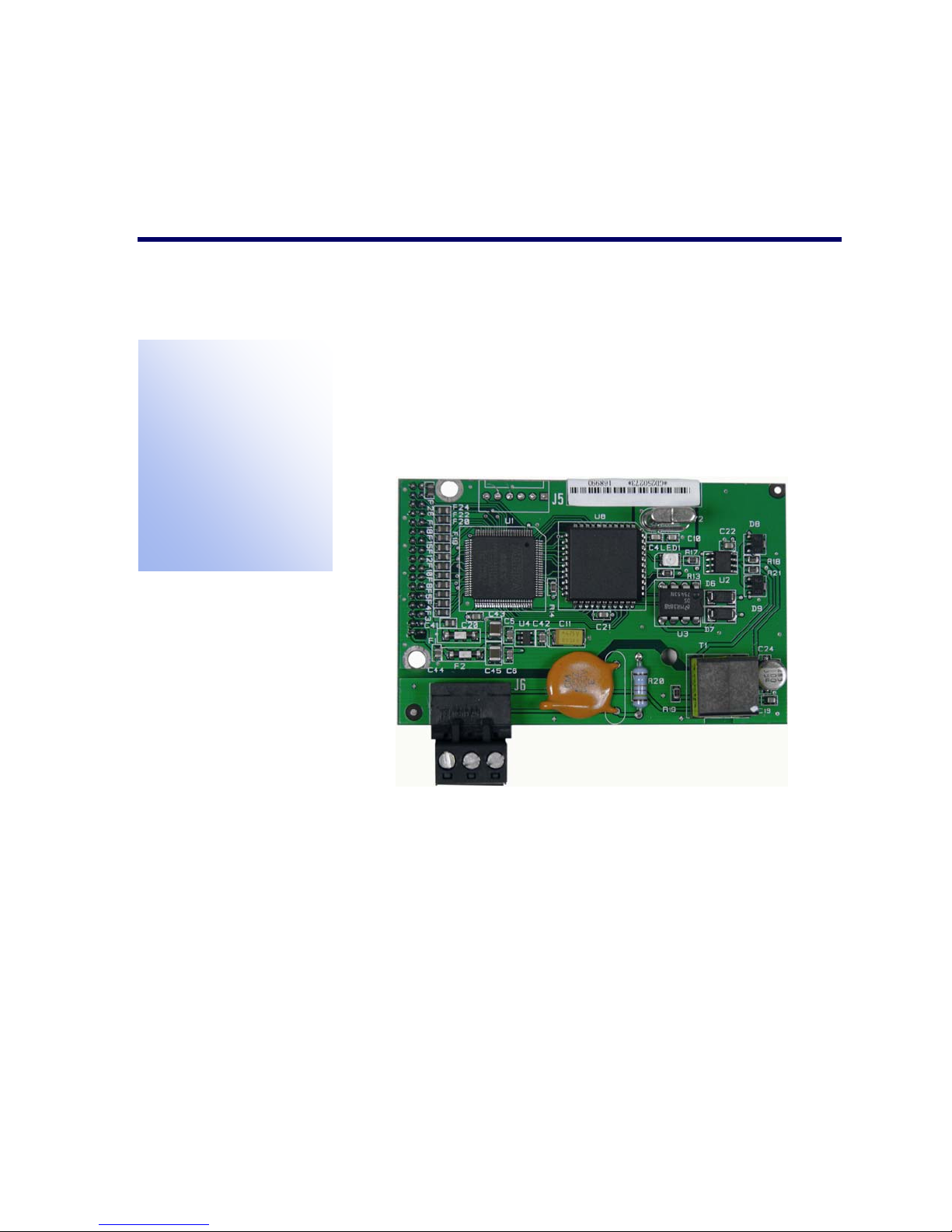
The A-B RIO Kit option enables the IND780 terminal to communicate to
Allen-Bradley Programmable Logic Controllers (PLCs) through direct
connection to the A-B RIO network. The option consists of a backplanecompatible I/O module, and software that resides in the IND780 terminal
to implement the data exchange. Figure 1-1 shows an A-B Rio interface
module.
Figure 1-1: A-B RIO Interface Module
The A-B RIO Kit option has the following features:
• A-B RIO Node Adapter Chip Set (licensed from Allen-Bradley) and termination
for the A-B network cable (blue hose) on a three-position removable terminal
block.
• User-programmable RIO communication parameters that are configured in
software set up through the terminal keyboard/display. The parameters are:
– 57.6K, 115.2K, or 230.4K baud rate
– 1/4, 1/2, 3/4, full rack (depends upon the number of scales/interface)
– Rack address
– Starting quarter
– Last rack designation
1-1

IND780 PLC Interface Manual
• Capability for bi-directional discrete mode communications of weight, display
increments, status, and control data between the PLC and the terminal.
• Capability for bi-directional block transfer communication of many IND780
terminal data variables.
Communications
The IND780 terminal utilizes component parts that are provided by Allen-Bradley to
ensure complete compatibility with the Allen-Bradley RIO network. An IND780
terminal is recognized as a RIO (Allen-Bradley) device by the PLC.
Each option connected to the Allen-Bradley RIO network represents a physical
node. The connection is facilitated by a three-position removable terminal block on
the option card. These terminals correspond to the terminals on the A-B PLC RIO
connector.
The wiring between the PLC and the RIO connector uses the standard RIO cable
used by Allen-Bradley (Figure 1-4). This cable is often referred to as the “blue
hose.” The cable installation procedures and specification including distance and
termination requirements are the same as recommended by Allen-Bradley for the
RIO network – refer to the A-B RIO scanner card documentation for further
information.
The IND780 terminal’s baud rate is programmed via setup at Communication >
PLC Interface > A-B RIO.
Node/Rack Address
Although each RIO option represents one physical node, the addressing of the node
is defined as a logical rack address. This address is chosen by the system designer,
and then programmed into the IND780 terminal and PLC. The IND780 terminal’s
address is programmed through Communication > PLC Interface > A-B RIO in the
setup menu. IND780 address entry can be in either decimal or octal, while most PLC
address entry is in octal.
The IND780 terminal’s setup capabilities allow selection of the logical rack address,
starting quarter, and designation of the last rack and the number of quarters
(Message Slots). Quarters must be contiguous in a single, logical rack, so the
starting quarter must be low enough to accommodate all of the required data for the
scales in a single, logical rack. The IND780 will determine the number of quarters
needed for the chosen data format and number of configurable Message Slots. It only
allows selection of the possible starting quarters and maximum Message Slots. Note
that floating point data format uses a complete rack address regardless of the
number of message slots used (max. 2).
1-2
Data Formats
The A-B RIO Kit option has two types of data exchanges: discrete data and block
transfer data.
Discrete data is continuously available. The A-B RIO Kit option has its own logical
rack address to send and receive information to and from the PLC. Discrete data is
always sent even when the optional block transfer data is used.
Block transfer data is available when the option is enabled through the IND780
Communication > PLC Interface –> A-B RIO setup menu. This data is used to pass
information that cannot be sent by the discrete data because of size or process speed
limitations. See the Data Definition section for more information.
Sharing a PLC Interface
Network Topology
IND780 PLC Interface Manual
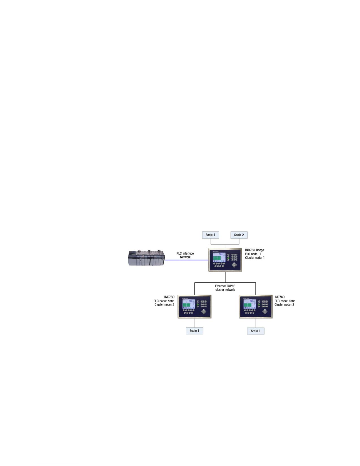
It is possible for a PLC interface to be concurrently shared between multiple
clustered terminals. The following example (Figure 1-2) shows a network topology
where a PLC interface located in one IND780 terminal, known as the bridge, is
shared across the terminal’s Ethernet TCP/IP cluster.
Figure 1-2: A-B RIO Network Topology
Up to 20 terminals can be connected in the cluster. However, the number of
message slots available for communications depends on the type of PLC interface.
All available PLC message slots can be configured to send or receive data to or
from the remote terminals via the cluster. Refer to the appropriate PLC chapters in
the IND780 PLC Interface Manual for further details on message slots’ limitations.
To allow bridging of the PLC interface, first a cluster network must be set up among
the IND780 terminals. Once the cluster is established, configure the PLC interface
on the bridge terminal, set up its data format and assign the required local or
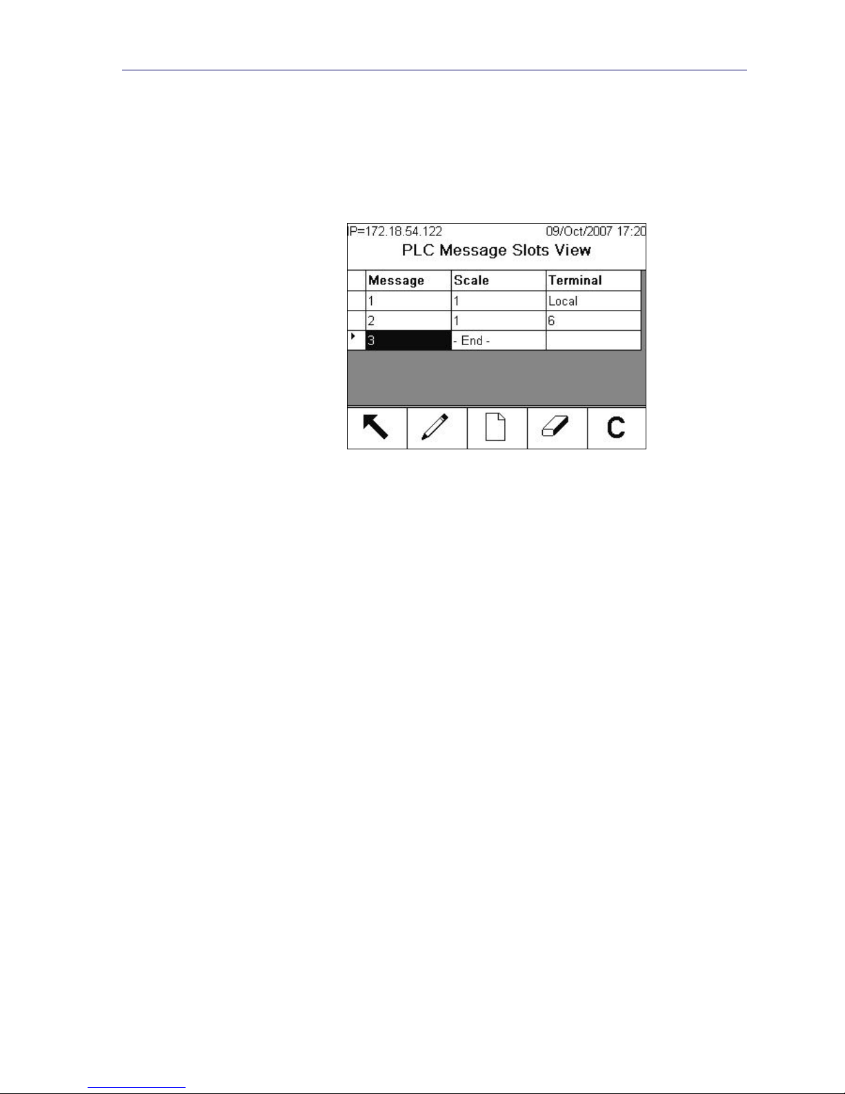
remote scale’s data to the message slots. Figure 1-3 shows an example of two
message slots, the first being allocated to scale 1 of the local bridge terminal and
1-3
IND780 PLC Interface Manual
a second slot to scale 1 of the remote terminal node 6. For details on configuring
the PLC interface in a cluster terminal, refer to the Software Setup section, below.
The use of PLC interface sharing is not recommended when real time weight or rate
information is required by the PLC for fast process control. The determinism of the
terminal’s PLC interface data update rate is influenced and limited by the
characteristics of Ethernet TCP/IP communications used in the cluster network.
Data Definition
The A-B RIO Kit option uses two types of data for its communication with PLCs:
discrete data and block transfer data. Discrete data is always available. The data
transfer is accomplished via the PLC’s I/O messaging. Block transfer data is only
available if this data option is enabled through the Communication > PLC Interface >
A-B RIO setup menu. If the block transfer data option is enabled, it is provided in
addition to the discrete data. Block transfer data requires “block transfer” ladder
sequence programming to accomplish the data transfer between the IND780 and
PLC.
Data Integrity
The IND780 has specific bits to allow the PLC to confirm that data was received
without interrupt and the IND780 is not in an error condition. It is important to
monitor these bits. Any PLC code should use them to confirm the integrity of the data
received from the IND780. Refer to the data charts for specific information regarding
the Data OK, Update in Progress, Data Integrity bits and their usage.
Figure 1-3: PLC Message Slots View Screen
Discrete Data
Five formats of discrete data are available with the A-B RIO Kit option: Integer,
divisions, floating point, template and application. Only one type of data format may
be selected and used by IND780’s sharing the same A-B RIO logical rack address.
1-4

IND780 PLC Interface Manual
The integer and division formats allow bi-directional communication of discrete bit
encoded information or 16 bit binary word (see Table 1-7 and Table 1-8 for
explanation) numerical values. The IND780 provides one quarter rack of data per
Message Slot.
The floating-point format allows bi-directional communication of discrete bit encoded
information or numeric data encoded in IEEE 754, single precision floating point
format. The IND780 provides one-half rack of data per Message Slot. In floating
point format, the IND780 will populate a complete rack of data regardless if one or
two Message Slots are used.
The format of discrete data will affect the amount of rack space required. Integer and
division formats require one-quarter rack per IND780 (two 16-bit words of input and
two 16-bit words of output data) Message Slot. One IND780, with 1 Message Slot,
would use a quarter rack; two IND780’s, with 1 Message Slot, would use a half
rack; three IND780’s, with 1 Message Slot, would use three-quarters of a rack; and
four IND780’s, with 1 Message Slot, would use a full rack.
The floating-point format requires more space per IND780 because floating point
data uses two 16-bit words of data to represent just the numeric data alone. The
floating point format uses one-half rack per IND780 (four 16-bit words of input and
four 16-bit words of output data) Message Slot.
Selection of the appropriate format depends on issues such as the range or capacity
of the scale used in the application. The integer format can represent a numerical
value up to 32,767. The division format can represent a value up to 32,767 scale
divisions (increments). The floating-point format can represent a value encoded in
IEEE 754, single precision floating point format.
Floating point is the only data format that includes decimal point information. All
other formats ignore decimal points. Accommodation of decimal point location
must take place in the PLC logic, when it is needed with these formats.
Another issue is the type of information communicated between the IND780 and
PLC for the application. Because the floating point format has more space for its
data, it has additional information that can be sent or received without using the
optional block transfer data. Please see each format’s detailed description of the
data available, to determine which is most suitable for the specific application.
Changing the Data Format to be used by the IND780 will cause all Message Slots
to be cleared. Data format is set up in the Communication > PLC Interface > Data
Format screen.
1-5
IND780 PLC Interface Manual
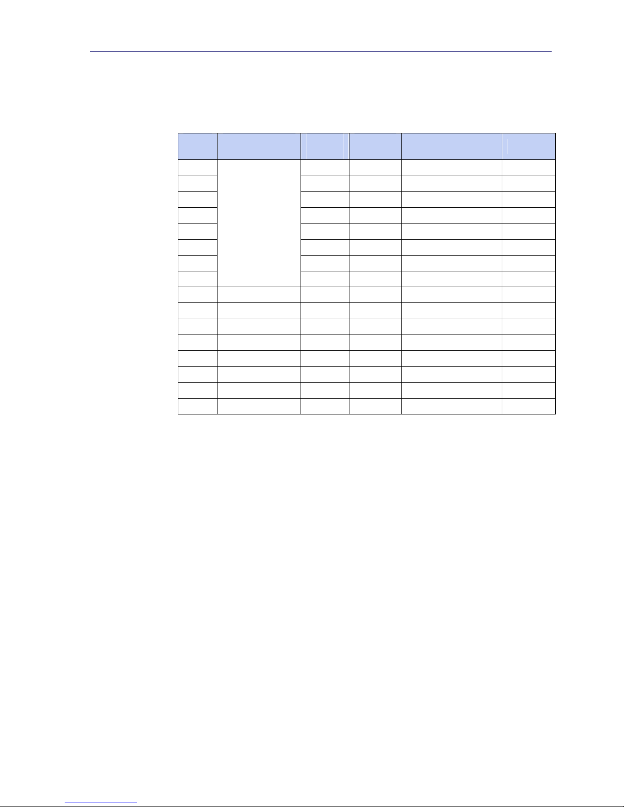
Examples
IND780 Displays: 0 2.00 51.67 250.00
Integer 0 200 5167 25000
Division 0 200 5167 25000
Floating Point 0 2.0 51.67 250.0
Any of the formats could be used in this case.
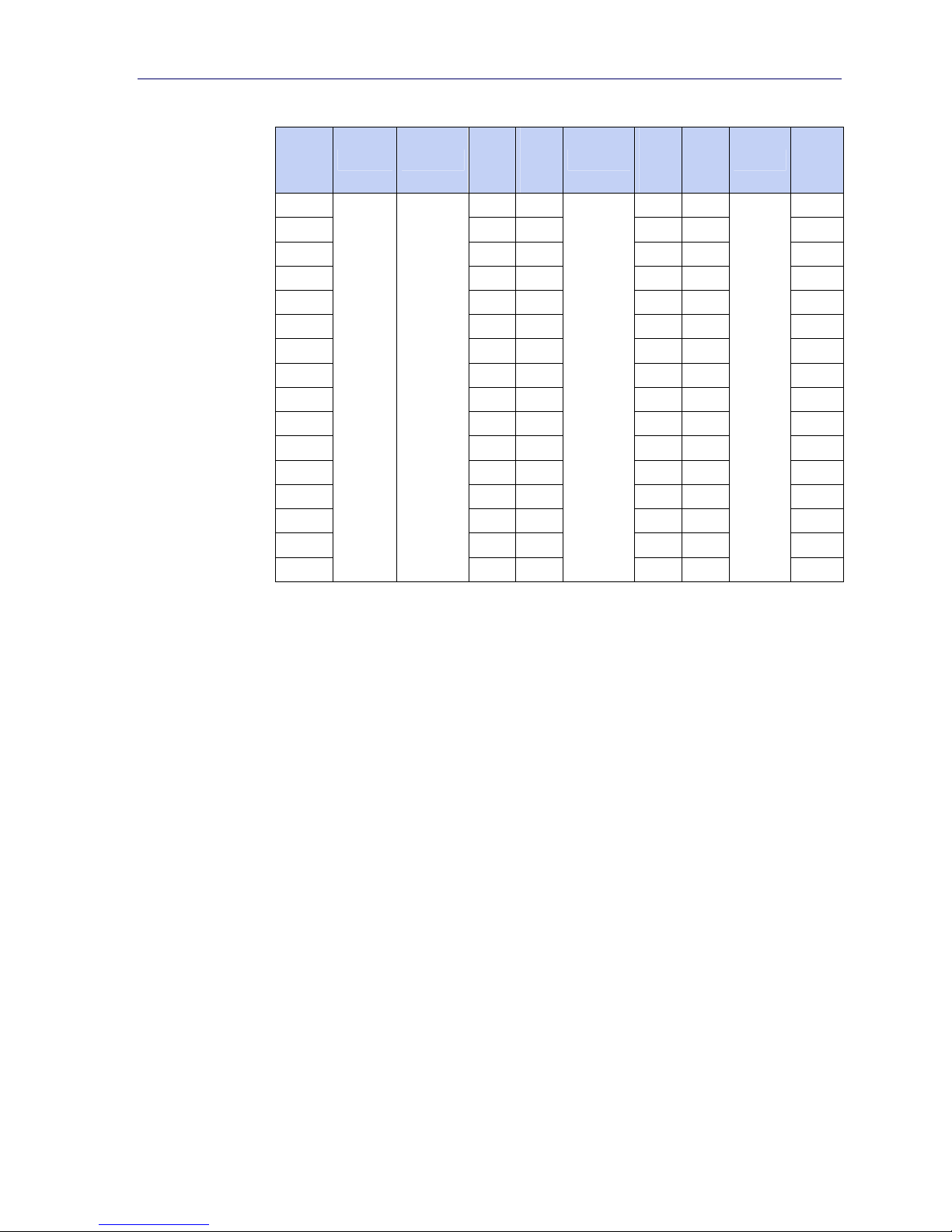
IND780 Displays: 0 200 5160 50000
Integer 0 200 5160 -(15536)
Division 0 20 516 5000
Floating Point 0 200.0 5160.0 50000.0
The integer format could not be used because it would send a
negative value once the weight exceeded 32,767.
250 x .01 scale
Format sent:
50,000 x 10 scale
Format sent:
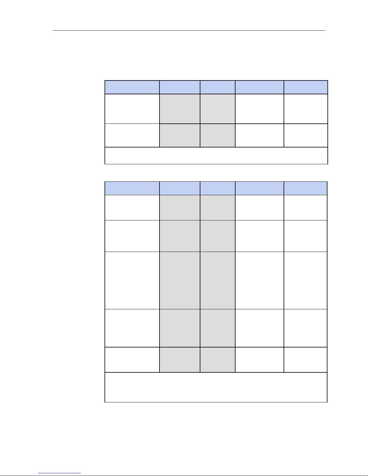
150 x .001 scale
IND780 Displays: 0 2.100 51.607 150.000
Format sent:
Integer 0 2100
Division 0 2100
Floating Point 0 2.1 51.607 150.0
The integer and division formats could not be used because they
would send a negative value once the weight exceeded 32.767.
−(13929)
−(13929)
18928
18928
Byte Order
Word Swap takes the IEE 754 single-precision floating point format and swaps the
two words in the 32-bit double word. This format is compatible with RSLogix 5000
processors.
Byte Swap makes the floating point format compatible with S7 PROFIBUS.
Historic makes the floating point format compatible with PLC 5.
Message Slots
The integer and division formats provide one-quarter rack (two 16-bit words of
input and two 16-bit words of output data) per Message Slot. Each message slot
1-6

IND780 PLC Interface Manual
is assigned to a local or remote scale and scales may be repeated in additional
message slots. Remote scales must reside in an IND780 Ethernet TCP clustered to
the IND780 containing the A-B RIO interface. Depending upon the starting quarter
there may be up to four Message Slots provided. Each Message Slot’s first input
word provides scale weight data and the input weight data may be selected by the
PLC using the Message Slot’s second output word bit 0, bit 1 and bit 2. Table 1-1
and Table 1-2 provide input and output words and word usage information.
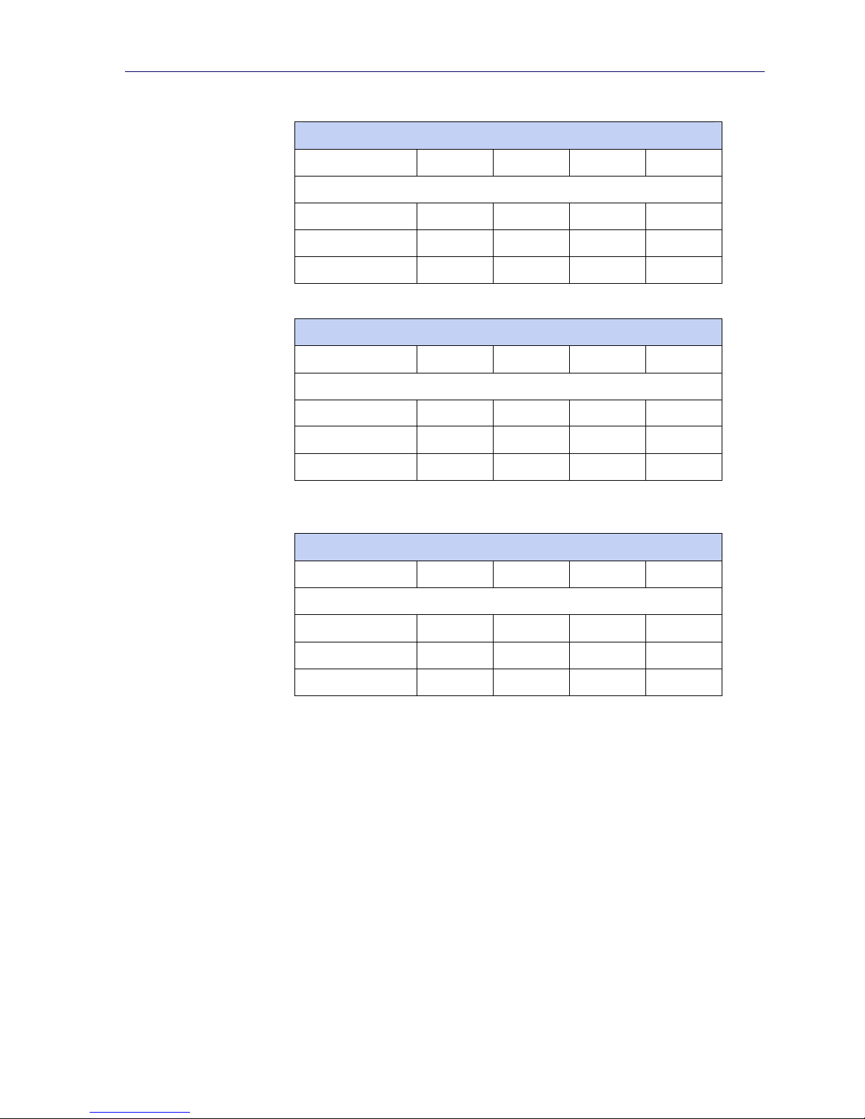
Table 1-1: PLC Input Words and Word Usage (Integer and Division), BT Disabled
PLC Input
Words
0
1
2
3
4
5
6
7
Word Usage
Start Quarter 1
(Group 0)
Message Slot 1
Weight Data
Message Slot 1
Scale Status
Message Slot 2
Weight Data
Message Slot 2
Scale Status
Message Slot 3
Weight Data
Message Slot 3
Scale Status
Message Slot 4
Weight Data
Message Slot 4
Scale Status
Word Usage
Start Quarter 2
(Group 2)
- - -
- - -
Message Slot 1
Weight Data
Message Slot 1
Scale Status
Message Slot 2
Weight Data
Message Slot 2
Scale Status
Message Slot 3
Weight Data
Message Slot 3
Scale Status
Word Usage
Start Quarter 3
(Group 4)
- -
- -
Message Slot 1
Weight Data
Message Slot 1
Scale Status
Message Slot 2
Weight Data
Message Slot 2
Scale Status
Word Usage
Start Quarter 4
(Group 6)
-
-
Message Slot 1
Weight Data
Message Slot 1
Scale Status
Table 1-2: PLC Output Words and Word Usage (Integer and Division), BT Disabled
PLC Output
Words
0
1
2
3
Word Usage
Start Quarter 1
(Group 0)
Message Slot 1
Weight Data
Message Slot 1
Scale
Command
Message Slot 2
Weight Data
Message Slot 2
Scale
Command
Word Usage
Start Quarter 2
(Group 2)
- - -
- - -
Message Slot 1
Weight Data
Message Slot 1
Scale
Command
Word Usage
Start Quarter 3
(Group 4)
- -
- -
Word Usage
Start Quarter 4
(Group 6)
1-7

IND780 PLC Interface Manual
PLC Output
Words
4
5
6
7
Word Usage Word Usage Word Usage Word Usage
Start Quarter 1 Start Quarter 2 Start Quarter 3 Start Quarter 4
(Group 0) (Group 2) (Group 4) (Group 6)
Message Slot 3
Weight Data
Message Slot 3
Scale
Command
Message Slot 4
Weight Data
Message Slot 4
Scale
Command
Message Slot 2
Weight Data
Message Slot 2
Scale
Command
Message Slot 3
Weight Data
Message Slot 3
Scale
Command
Message Slot 1
Weight Data
Message Slot 1
Scale
Command
Message Slot 2
Weight Data
Message Slot 2
Scale
Command
-
-
Message Slot 1
Weight Data
Message Slot 1
Scale
Command
The floating point format provides one-half rack (four 16-bit words of input and up
to four 16-bit words of output data) per Message Slot. See Table 1-5 and Table
1-6 for details.
The number of Message Slots is setup in Communications > PLC Interface > Data
Format setup menu (Figure 1-8).
Table 1-3: PLC Input Words and Word Usage (Integer and Division), BT Enabled
PLC Input
Words
0 Not Valid Reserved Reserved Reserved
1 Not Valid Reserved Reserved Reserved
2 Not Valid
3 Not Valid
4 Not Valid
5 Not Valid
6 Not Valid
7 Not Valid
Word Usage
Start Quarter 1
(Group 0)
Word Usage
Start Quarter 2
(Group 2)
Message Slot 1
Weight Data
Message Slot 1
Scale Status
Message Slot 2
Weight Data
Message Slot 2
Scale Status
Message Slot 3
Weight Data
Message Slot 3
Scale Status
Word Usage
Start Quarter 3
(Group 4)
- -
- -
Message Slot 1
Weight Data
Message Slot 1
Scale Status
Message Slot 2
Weight Data
Message Slot 2
Scale Status
Word Usage
Start Quarter 4
(Group 6)
-
-
Message Slot 1
Weight Data
Message Slot 1
Scale Status
1-8

IND780 PLC Interface Manual
Table 1-4: PLC Output Words and Word Usage (Integer and Division), BT Enabled
PLC Output
Words
Word Usage
Start Quarter 1
(Group 0)
Word Usage
Start Quarter 2
(Group 2)
Word Usage
Start Quarter 3
(Group 4)
Word Usage
Start Quarter 4
(Group 6)
0 Not Valid Reserved Reserved Reserved
1 Not Valid Reserved Reserved Reserved
2 Not Valid
Message Slot 1
Weight Data
- -
Message Slot 1
3 Not Valid
Scale
- -
Command
4 Not Valid
Message Slot 2
Weight Data
Message Slot 2
5 Not Valid
Command
6 Not Valid
Message Slot 3
Weight Data
Message Slot 3
7 Not Valid
Command
Scale
Scale
Message Slot 1
Weight Data
Message Slot 1
Scale
Command
Message Slot 2
Weight Data
Message Slot 2
Scale
Command
-
-
Message Slot 1
Weight Data
Message Slot 1
Scale
Command
Table 1-5: PLC Floating Point Input Words
PLC Output
Words
Bits 0 - 7 Bits 8 - 15
0 Message Slot 1, Reserved
1
2
3
Message Slot 1 Floating Point
data
Message Slot 1 Floating Point
data
Message Slot 1, Scale Status, See
Message Slot Table
4 Message Slot 2, Reserved
5
6
Message Slot 2 Floating Point
data
Message Slot 2 Floating Point
data
Message Slot 1, Command
Response, See Message Slot
Table
Message Slot 1 Floating Point
data
Message Slot 1 Floating Point
data
Message Slot 1, Scale Status, See
Message Slot Table
Message Slot 2, Command
Response, See Message Slot
Table
Message Slot 2 Floating Point
data
Message Slot 2 Floating Point
data
7
Message Slot 2, Scale Status, See
Message Slot Table
Message Slot 2, Scale Status, See
Message Slot Table
1-9

IND780 PLC Interface Manual
Table 1-6: PLC Floating Point Output Words
PLC Output
Words
0 Reserved
1 Message Slot 1 Command
2 Message Slot 1 Floating Point data
3 Message Slot 1 Floating Point data
4 Message Slot 2 Command
5 Message Slot 2 Floating Point data
6 Message Slot 2 Floating Point data
7 Not Used
Usage
Integer and Division
When one of these formats is selected, the IND780 will have one quarter rack of
data: two 16-bit words for input data and two 16-bit words for output data in each
Message Slot. The PLC’s input data will contain one 16-bit word for the scale’s
weight information and one 16-bit word for bit encoded status information for each
Message Slot. The IND780 will send specific weight data to the PLC input data
based on the data it receives from the PLC’s output data. The PLC’s output words
consist of one 16-bit integer value, which may be used to download a tare or
target, and one 16-bit word for bit encoded command information.
Table 1-7 and Table 1-8 provide detailed information on the integer (int) and
division (div) data formats. Read data refers to the PLC’s input data and write data
refers to the PLC’s output data.
1-10

IND780 PLC Interface Manual
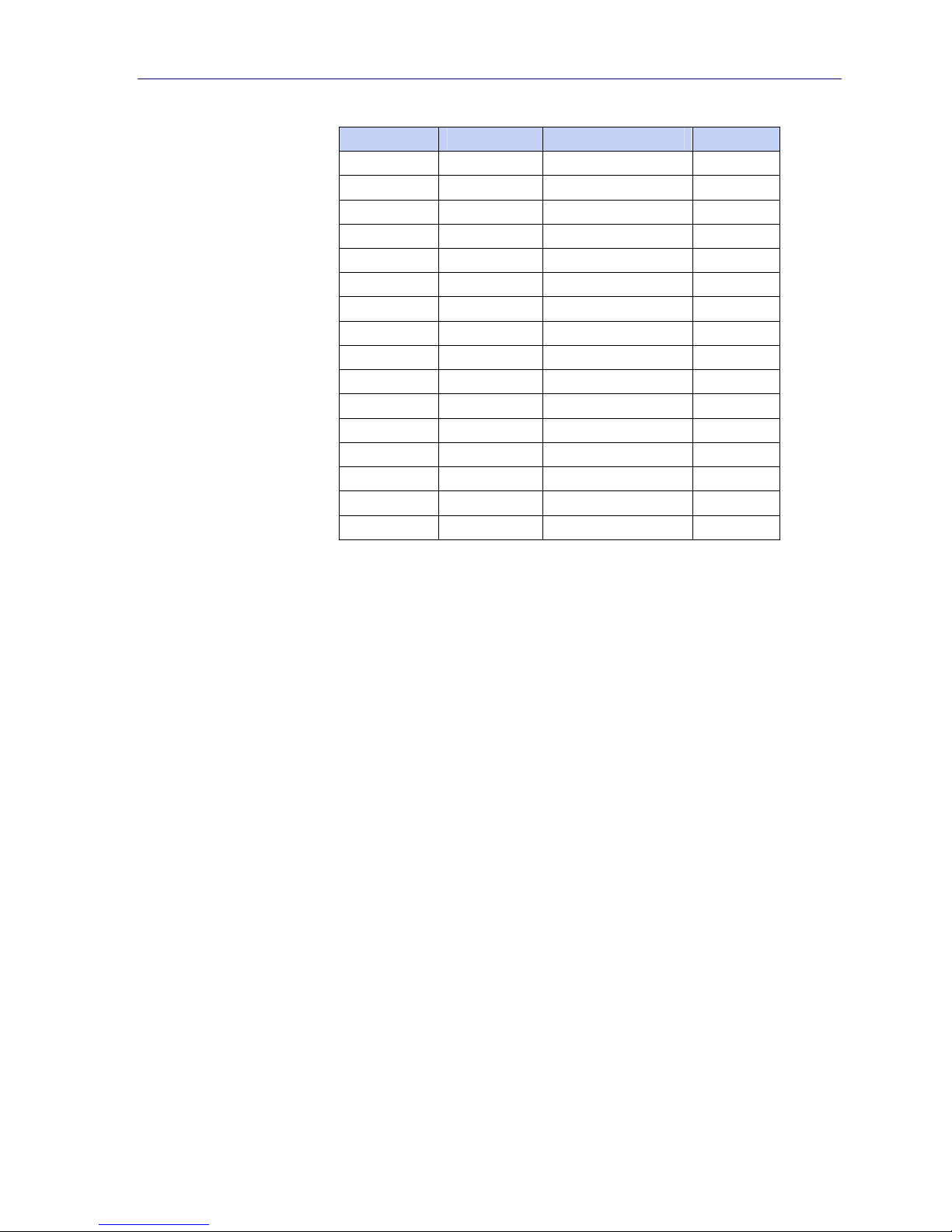
Table 1-7: Discrete Read Integer or Division – IND780 >> PLC
Octal Address WORD 0 IN1 WORD 1 IN Bit number
0 X Feed2
1 X Fast Feed2 1
2 X Tolerance OK3 2
3 X Under low tolerance4 3
4 X Over high tolerance4 4
5 X Comparator 35 5
6 X Comparator 25 6
7 X Comparator 15 7
10 X ENTER key6 8
11 X Input 17 9
12 X Input 27 10
13 X Input 37 11
14 X Motion8 12
15 X Net mode9 13
16 X Update in progress10 14
17 X12 Data OK11 15
0
Notes for Table 1-7:
1 WORD 0 is a 16-bit, signed integer value that may represent the scale’s gross, net, tare, target,
rate or displayed weight. Three bits, set by the PLC in the output word, designate what data is
sent by the terminal in this word.
2 Bit 0 and Bit 1 are used only in in material transfer mode.
3 Bit 2 indicates that tolerance is OK in both material transfer mode and over/under mode.
4 When equal to 1, Bit 3 and Bit 4 indicate that target is under negative tolerance or over positive
tolerance, respectively.
5. Bits 5, 6 and 7 provide Comparators 1, 2 and 3 statuses. If the comparator is active, the
respective bit is set to 1.
6 Bit 8 is set to a “1” when the ENTER key is pressed on the keypad of the terminal. The bit
remains on for 30 seconds then resets to 0.
7 Bit 9, bit 10, and Bit 11 mirror the state of the first three discrete inputs on the internal I/O board
slot 5 (0.5.1, 0.5.2 and 0.5.3). If the input is “ON” then the bit is set to a “1”.
8 Bit 12 is set to a “1” when the scale is in motion (unstable).
9 Bit 13 is set to a “1” when the scale is in net mode (a tare has been taken).
10 Bit 14 is set to a “1” when the terminal is in the process of updating its data for the PLC scanner.
The PLC should ignore ALL of the data in this case and simply re-scan it.
11 Bit 15 is set to a “1” when the scale is operating properly (NOT
power-up, in expanded mode, or in setup mode).The PLC program should continuously monitor
this bit and the PLC processor rack fault bit (see A-B RIO PLC documentation) to determine the
validity of the discrete and/or explicit data transfer. While in the setup mode word 0 data may be
present; do not use the data under this condition as the communication connection may stop at
any time.
12 When number is negative, word 0 Bit 15 is high and is the least significant bit. Otherwise, when
the number is positive, Bit 15 is the most significant bit.
over capacity, under capacity, in
1-11
IND780 PLC Interface Manual
Table 1-8: Discrete Write Integer or Division – PLC >> IND780
Octal Address WORD 0 OUT1 WORD 1 OUT Bit number
0 X Select 12
1 X Select 22 1
2 X Select 32 2
3 X Load Tare3 3
4 X Clear4 4
5 X Tare5 5
6 X Print6 6
7 X Zero7 7
10 X Abort/Start Target8 8
11 X Display mode9 9
12 X Display mode9 10
13 X Display mode9 11
14 X Output 110 12
15 X Output 210 13
16 X Output 310 14
17 X Load Target11 15
0
Notes for Table 1-8:
1 WORD 0 is a 16-bit, signed integer value that may represent the scale’s tare or target value to be
downloaded. Bit 3 or Bit 15 is then triggered to instruct the terminal to load the value into either
the tare or target register.
2 A binary value in Bit 0, Bit 1, and Bit 2 select the data that will be sent by the terminal in
Discrete Read WORD 0. 0 = gross weight, 1 = net weight, 2 = displayed weight, 3 = tare weight,
4 = target, 5 = rate, 6 and 7 = reserved. Any value greater than 7 will cause gross weight to be
sent.
3 A transition from “0” to “1” loads the value from WORD 0 into the tare register of the IND780; the
IND780 will use the loaded value as the tare.
4 A transition from “0” to “1” initiates a CLEAR command.
5 A transition from “0” to “1” initiates a TARE command.
6 A transition from “0” to “1” initiates a PRINT command.
7 A transition from “0” to “1” initiates a ZERO command.
8 If Bit 8 is set to “0”, all of the scale’s target logic is aborted. Setting Bit 8 to “1” again restarts the
terminal’s target logic. Note: The PLC must start the target logic before the PLC can abort the
target logic.
9 Bits 9-11 control Display Mode. A command is written to pd0119. Note that pd0119=0 for
normal display mode, 1 = display message 1 (aw0101), 2 = display message 2 (aw0102), 3
= display message 3 (aw0103), 4 = display message 4 (aw0104), 5 = display message 5
(aw0105), 6 = Start ID1 sequence, 7 = display message that is written into pd0118. Note: Until
these bits are used pd0119 will be set at 0. Change of state of any of these bits resets PLC input
word, Bit 8, Enter Key.
10 Bit 12, Bit 13, and Bit 14 can be used to control the state of the first three discrete outputs on
the terminal’s internal I/O board in slot 5. These are addressed as 0.5.1, 0.5.2, and 0.5.3.
Setting the bit to a “1” state causes the output to be turned ON. This action will occur regardless
of the discrete output assignment within the IND780.
11 When Bit 15 is changed from “0” to “1” the value in WORD 0 is loaded into the target register in
the terminal and transferred into the target logic.
1-12

IND780 PLC Interface Manual
Floating Point
Operational Overview
The IND780 uses integer commands from the PLC to select the floating point
weight output data. The IND780 recognizes a command when it sees a new value
in the Message Slot command word. If the command has an associated floating
point value (for example: loading a target value), it must be loaded into the
floating point value words before the command is issued. Once the IND780
recognizes a command, it acknowledges the command by setting a new value in
the command acknowledge bits of the scale’s command response word. The
IND780 also tells the PLC what floating point value is being sent (via the floating
point input indicator bits of the command response word). The PLC should wait
until it receives the command acknowledgment from the IND780 before sending
another command.
The IND780 can report two types of values to the PLC: real-time and static. When
the PLC requests a real-time value, the IND780 acknowledges the command from
the PLC once but sends and updates the value at every interface cycle update. Note
that PLC RIO scanner baud rate and the number of racks in the scanner
configuration will have an impact on the PLC input data update rate. If the PLC
requests a static value, the IND780 acknowledges the command from the PLC
once and updates the value once. The IND780 will continue to send this value
until it receives a new command from the PLC. Gross weight and net weight are
examples of real-time data. Tare weight, target, feed, and tolerance values are
examples of static data.
The IND780 can send a rotation of up to nine different real-time values. The PLC
sends commands to the IND780 to add a value to the rotation. Once the rotation is
established, the PLC must instruct the IND780 to begin its rotation automatically,
or the PLC may control the pace of rotation by instructing the IND780 to advance
to the next value. Note that once the rotation is established the rotation will be
present on all message slots. If the IND780 is asked to automatically alternate its
output data, it will switch to the next value in its rotation at the next Interface cycle
update. (The Interface cycle update has an update rate of up tp 17 Hz or
60 milliseconds.) Note that PLC RIO scanner baud rate and the number of racks in
the scanner configuration will have an impact on the PLC input data update rate.
The PLC may control the rotation by sending alternate report next field commands
(1 and 2). When the PLC changes to the next command the IND780 switches to
the next value in the rotation order. Each message slot can be controlled
separately. The IND780 stores the rotation in its shared data so the rotation does
not have to be re-initialized after each power cycle. When the PLC does not set up
an input rotation, the default input rotation consists of gross weight only. See the
floating-point command examples in
information. The method of handling string and floating point data varies between
Allen-Bradley PLC generations. The IND780 provides floating point data in the
order entered in Data Format setup.
Table 1-11 through Table 1-14 for additional
1-13
IND780 PLC Interface Manual
Table 1-9 to Table 1-12 provide detailed information on the floating-point data
format. Read data refers to the PLC’s input data and write data refers to the PLC’s
output data.
Octal
Address
10 FP Input Ind 17 X X ENTER key8 8
11 FP Input Ind 27 X X Input 19 9
12 FP Input Ind 37 X X Input 29 10
13 FP Input Ind 47 X X Input 39 11
14 FP Input Ind 57 X X Motion10 12
15 Data integrity111 X X Net mode12 13
16 Cmnd Ack 113 X X Data integrity 211 14
17 Cmnd Ack 213 X X Data OK14 15
WORD 0 Command
0 X X Feed2 0
1 X X Fast Feed2 1
2 X X Tolerance OK3 2
3 X X Under Negative Tolerance4 3
4 X X Over Positive Tolerance4 4
5 X X Selected scale5 5
6 X X Custom Bit
7
Table 1-9: Discrete Read Floating Point – IND780 >> PLC
Response
RESERVED
WORD 1
1
WORD 2
FP value
X X Custom Bit6 7
FP value
1
WORD 3
Status
6
Bit number
6
Notes for Table 1-9:
1 The bits in WORD 1 and WORD 2 are a single-precision floating point value that may represent
the scale’s gross, tare, net, target, fine gross, fine tare, fine net, or filter setting data. The PLC
command in the respective scale’s output word determines what data will be sent.
2 Bit 0 and Bit 1 are used only in material transfer mode.
3 Bit 2 indicates that tolerance is OK in both material transfer and over/ under modes.
4 Bit 3 and Bit 4 are active in both material transfer and over/under modes.
5 Bit 5 will be set to a “1” when the associated scale is selected on the IND780 console panel.
6 Bit 6 and Bit 7 are user defined, and corresponds to user’s Task Expert Application usage. Bit 6
is associated to Shared Data Variable ASxx01, instance by scale. Bit 7 is associated with Shared
Data Variable ASxx02, instance by scale.
7 The Floating Point Input Indication bits (WORD 0, Bits 8-12) are used to determine what type of
data is being sent in the floating point value (WORD 1 and WORD 2). These bits correspond to a
decimal value of 0-31 that represents a particular type of data. See the Floating Point Input
Indication Table to determine what type of data.
8 Bit 8 is set to a “1” when the ENTER key is pressed on the terminal’s keypad. The bit clears to “0”
when the PLC sends floating point command 75 to the IND780 terminal or after 30 seconds of
no ENTER key activity.
9 Bit 9, Bit 10, and Bit 11 mirror the state of the first three discrete inputs of the internal I/O board
in slot 5 (0.5.1, 0.5.2 and 0.5.3). If the input is “ON” then the bit is set to a “1”.
10 Bit 12 is set to a “1” when the scale is in motion (unstable).
11 The Data Integrity bit in WORD 0 - bit 13 is used in conjunction with the bit in WORD 3 - bit 14
to insure that the floating point data is valid. For the data to be valid both bits must have the
same polarity. These bits will change to the opposite state every interface update cycle. If they do
not have the same value the data is invalid and the PLC should ignore ALL of the data in this
case and re-scan it.
1-14

IND780 PLC Interface Manual
12 Bit 13 is set to a “1” when the scale is in net mode (a tare has been taken).
13 Bit 14 and Bit 15 (Command Acknowledge bits) are used by the terminal to inform the PLC that
it has received a new, valid command. The terminal rotates sequentially among values 1, 2, 3,
1, 2, 3, 1, 2, … to acknowledge it has processed a new command.
14 Bit 15 is set to a “1” when the scale is operating properly (NOT over capacity, under capacity, in
power-up, or in setup mode). The PLC program should continuously monitor this bit and the PLC
processor rack fault bit (see A-B RIO PLC documentation) to determine the validity of the discrete
and/or explicit data transfer. While in the setup mode the input floating data will be set to 0;
additionally the communication connection may stop at any time.
Table 1-10: Floating Point Input Indication
Dec Data
0 Gross Weight*
1 Net Weight*
2 Tare Weight*
3 Fine Gross Weight*
4 Fine Net Weight*
5 Fine Tare Weight*
6 Rate
7 ALxx01 – SDV, instance by scale **
8 ALxx02 – SDV, instance by scale **
9 AJxx01 – SDV, instance by scale **
10 AJxx02 – SDV, instance by scale **
11 Low-pass filter frequency, instance by scale
12 Notch filter frequency, instance by scale
13 Target value, instance by scale
14 Target positive tolerance value, instance by scale
15 Target Fine Feed value, instance by scale
16 Target negative tolerance value, instance by scale
17 Target spill value, instance by scale
18 Primary units, low increment size, instance by scale
19–28 Not used
29 Last IND780 error code, instance by scale
30 No data response – command successful
31 No data response – command failed
* These are real-time fields that the PLC may request either through an input rotation or a report
command. All other fields may only be requested through a report command.
** SDV means Shared Data Variable.
1-15
IND780 PLC Interface Manual
Octal
Address
0 X X X X 0
1 X X X X 1
2 X X X X 2
3 X X X X 3
4 X X X X 4
5 X X X X 5
6 X X X X 6
7 X X X X 7
Reserved
10 X X X X 8
11 X X X X 9
12 X X X X 10
13 X X X X 11
14 X X X X 12
15 X X X X 13
16 X X X X 14
17
Table 1-11: Discrete Write Floating Point – PLC >> IND780
WORD
WORD 0 WORD 1
Command
Word
Message
Slot 13
WORD
21
FP load
value
31
FP load
value
X X
WORD 42
Command
Word
Message
Slot 2
2,3
WORD
1,2
5
FP load
value
X X
WORD
6
FP load
value
1,2
WORD 7
Not Used
Bit
number
15
Notes for Table 1-11:
1 The Bits in WORD 2 and WORD 3 (and WORD 5 and WORD 6) are a single-precision floating
point value. This value is used with the command in WORD 1 (or WORD 4) to instruct the
terminal to download the floating point value into the field specified in the command.
2 These words are only used if a second Message Slot is desired.
3 The command words WORD 1 and WORD 4 (for the second Message Slot) are used to instruct
the IND780 what data to send in the discrete read data, to load the floating point data in the
write command, and to control the IND780 discrete outputs or display. See Table 1-12, the PLC
Output Command Table, for a list of the available commands and their respective decimal or
hex value.
Not all commands will require a value in the floating point load value words.
1-16

IND780 PLC Interface Manual
92
93
Table 1-12: PLC Output Command Table (Floating Point Only)
Dec Hex Command SDName Dec Hex Command SDName
0 00
1 01 Report next rotation field
2 02 Report next rotation field
3 03 Reset rotation 80 50 Set normal display mode
10 0a Report gross weight
11 0b Report net weight
12 0c Report tare weight
13 0d Report fine gross weight
14 0e Report fine net weight
15 0f Report fine tare weight
16 10 Report Rate
Report next rotation field @ next
Interface cycle update
1,3
1
1,2
78 4e Disable LCD display 7
1,2
79 4f Enable LCD display 7
1,3
81 51 Display message 1
1,3
82 52 Display message 2
1,3
83 53 Display message 3
1,3
84 54 Display message 4
1,3
85 55 Display Message 5
1,3
86 56 Start ID1 sequence
87 57 Display SDV PD0118
76
4c Start ID2 sequence
17 11 Report SDV ALxx01 6 88 58 Disable weight display 7
18 12 Report SDV ALxx02 6 89 59 Enable weight display 7
19 13 Report low-pass filter frequency3 90 5a Set discrete output 0.5.1 “ON” 7 DI0505
20 14 Report notch filter frequency 3 91 5b Set discrete output 0.5.2 “ON” 7 DI0506
21 15 Report Target value
22 16 Report Positive Tolerance
23 17 Report Fine Feed
24 18 Report (-) Tolerance value
25 19 Report spill value
27 1b Report AJxx01
28 1c Report AJxx02
3,10
SPxx05
3,10
3,10
3,10
3,5,,6
AJxx01
3,5,,6
AJxx02
SPxx11
SPxx10 100 64 Set discrete output 0.5.1 “OFF” 7 DI0505
3,10
SPxx12 101 65 Set discrete output 0.5.2 “OFF” 7 DI0506
SPxx09 102 66 Set discrete output 0.5.3 “OFF” 7 DI0507
6
5c Set discrete output 0.5.3 “ON” 7 DI0507
6
5d Set discrete output 0.5.4 “ON” 7 DI0508
6
103 67 Set discrete output 0.5.4 “OFF”
6
104 68 Master control relay OFF
29 1d Report last error 3 105 69 Master control relay ON
30 1e Report primary increment size 3 110 6e Set target value
40 28 Add gross weight to rotation 7 111 6f Set target fine feed value
41 29 Add net weight to rotation 7 112 70 Set - tolerance value
42 2a Add tare weight to rotation 7 113 71 Set target value and apply
43 2b Add fine gross weight to rotation 7 114 72 Start target logic
44 2c Add fine net weight to rotation 7 115 73 Abort target logic
45 2d Add fine tare weight to rotation 7 116 74 Target use gross weight
46 2e Add rate to rotation 7 117 75 Target use net weight
47 2f Add ALxx01 to rotation
48 30 Add ALxx02 to rotation
5,6,7
ALxx01
5,6,7
ALxx02
6
118 76 Target use rate
6
119 77 Target, absolute weight 1 speed
60 3c Load numeric tare value 4 120 78 Target, absolute weight 2 speed
61 3d Pushbutton tare command 7 121 79 Enable target latching
62 3e Clear command 7 122 7a Disable target latching
63 3f Print command 7 123 7b Reset target latch 7 SPxx07
64 40 Zero command 7 124 7c Set target spill value
65 41 Select scale 1 7 131 83 Set + tolerance value
66 42 Select scale 2 7 160 a0 Apply scale setup 7 QC0149
67 43 Select next scale 7 161 a1 Write Calibration to EEProm 7
68 44 Custom print 17 CPxx01
69 45 Custom print 27 CPxx02
70 46 Custom print 37 CPxx03
71 47 Custom print 47 CPxx04
72 48 Custom print 57 CPxx05
73 49
Set low-pass filter corner
frequency
4
7
162 a2 Disable Tare on IND780 console
7
163 a3 Enable Tare on IND780 console 7
7
164 a4
7
165 A5
7
166 a6
167
Disable push button Tare on IND780
7,11
console
Enable push button Tare on IND780
7
console
Disable numeric Tare on IND780
7,11
console
Enable numeric Tare on IND780
a7
console
7
74 4a Set notch filter frequency 4 168 a8 Select scale 3 7
75 4b Reset ENTER key 7 169 a9 Select scale 4 7
7,9
PD0119
7,9
PD0119
7,9
PD0119
7,9
PD0119
7,9
PD0119
7,9
PD0119
7,9
PD0119
7,9
PD0119
7,9
PD0119
7
7, 12
7, 12
4,10, 13
7,10
7,10
7,10
SPxx05
4,10
4,10
4, 10, 14
7,10
SPxx04
7,10
SPxx04
SPxx04
7,10
SPxx06
7,10
SPxx06
4, 10
4,10
SPxx11
DI0508
7,10
SPxx08
7,10
SPxx08
7,11
1-17

IND780 PLC Interface Manual
Notes for Table 1-12:
1. A command that requests real-time fields from the terminal. The terminal updates this input data to the PLC
at the cycle update rate of the PLC interface.
2. A command used by the PLC to select the next field from the input rotation. The PLC must alternate between
these two commands to tell the terminal when to switch to the next field of the input rotation.
3. A command requiring the terminal to report a specific value in the PLC input message. As long as one of
these commands is sent in the Scale Command, the terminal will respond with the requested data and not
data from an input rotation. The data reported in the PLC input message is the data when the command was
issued.
4. A command that requires a floating point value output from the PLC to the terminal. The terminal reflects
back this value in the floating point data of the input message to the PLC.
5. A command used between the PLC and a Task Expert application. This data has a four-byte length and is
defined by the application.
6. Instance is by scale.
7. PLC input Message Slot floating point value will be 0 as long as command is present.
8. IND780 discrete output will be turned on or off regardless of assignment within the IND780.
9. A command is written to pd0119. Note that pd0119==0 for normal display, 1 = display message 1
(aw0101), 2 = display message 2 (aw0102), 3 = display message 3 (aw0103), 4 = display message 4
(aw0104), 5 = display message 5 (aw0105), 6 = Start ID1 sequence, 7 = display message that is written
into pd0118, 8 = Start ID2 sequence. Note: Until these commands are used pd0119 will be set at 0.
10. Target, Fine Feed, Tolerances, Restart, Abort and other Target variables are relative to each scale. Note:
Restart of an active Target will cause the associated outputs to cycle off then back on.
11. Does not disable the PLC tare functions.
12. Setting the master control relay OFF turns off all outputs and stops target logic. The target logic must be re-
started after the master control relay is turned ON.
13. Target logic must be restarted to apply the new target value.
14. New target value is applied when command is sent.
1-18

IND780 PLC Interface Manual
Floating Point Data Format and Compatibility
In Floating Point Data Format, the PLC and terminal exchange weight, target, and
tare data in single-precision floating-point format. The IEEE Standard for Binary
Floating-Point Arithmetic, ANSI/IEEE Standard 754-1985, specifies the format for
single-precision floating point numbers. It is a 32-bit number that has a 1-bit sign,
an 8-bit signed exponent, and a 23-bit mantissa. The 8-bit signed exponent
provides scaling of weight data. The 23-bit mantissa allows representation of 8
million unique counts.
Although the single-precision floating point number provides greater numerical
precision and flexibility than integer weight representations, it has limitations. The
weight representation may not be exact, particularly for the extended-resolution
weight fields for high-precision bases.
Some Allen-Bradley PLCs require special integrity checking to communicate
floating point numbers across the Remote I/O link. The Allen-Bradley PLC-5 and
KTX Scanner Card programs must check two data integrity bits to verify the integrity
of the floating point data it reads from the terminal. Allen-Bradley SLC programs
always read valid floating-point data from the terminal and do not have to make
special checks to guarantee the validity of the floating-point data. The Allen-Bradley
PLC-3 and PLC-5/250 cannot support terminals in floating point mode as they
cannot guarantee the integrity of the floating-point data.
There are two data integrity bits that the terminal uses to maintain data integrity
when communicating with the Allen-Bradley PLC-5 Remote I/O Scanner or KTX
Scanner Card. One bit is in the beginning word of the data; the second is in the
ending byte of the data for a scale slot. The PLC program must verify that both data
integrity bits have the same polarity for the data in the scale slot to be valid. There
is a possibility that the PLC program will see several consecutive invalid reads
when the terminal is freely sending weigh updates to the PLC-5. When the program
detects this condition, it should send a new command to the terminal.
The Allen-Bradley SLC PLC programs do not have to make special checks to
guarantee the validity of the floating-point data.
The method of handling string and floating point data varies between Allen-Bradley
PLC generations. The IND780 provides floating point data in the word order set up
by the user.
1-19
IND780 PLC Interface Manual
Floating Point Command Examples
Table 1-13 to Table 1-16 provide floating point command examples.
Table 1-13: Data Requirement: Only Net Weight Sent (Continuously) for Scale 1
Step #
1
(PLC sends command
to IND780 terminal to
report net weight)
2
(IND780 terminal
sees new command)
Scale Command
(From PLC)
11 (dec)
loaded into
command word
O
Scale Floating
Point Value
none
required
Command Response
From Terminal
Command ack. =1
F.P. ind. = 1 (net)
Floating Point
Value
Net weight in
floating point
As long as the PLC leaves the 11 (dec) in the command word, the IND780 terminal will update the
net value every interface update cycle.
Table 1-14: Data Requirement: Load Target Value = 21.75 for Scale 1
Step #
1
(PLC loads floating
point value first)
2
(PLC sends command
to set target 1 cutoff
value)
3
(IND780 terminal
sees new command ,
loads the value into
the target and ends a
return message to
indicate the new target
value)
Scale command
(from PLC)
110 (dec)
loaded into
command word
O
Scale Floating
Point Value
floating point
value =
21.75
floating point
value =
21.75
Command response
from terminal
Command ack. = 1
F.P. ind = 13
Floating Point
Value
Floating point
value = 21.75
(PLC instructs IND780
terminal to start
“using” new target
(IND780 terminal
sees new command)
The PLC should always wait to receive a command acknowledgment before sending the next
command to the IND780 terminal. After the PLC finishes loading its target value, it can resume
monitoring the weight information required by sending a command to report some type of weight or
set up a rotation of reported data.
1-20
4
value)
5
114 (dec)
loaded into
command word
O
Command ack. = 2
F.P. ind = 30
(null value)
 Loading...