

Mettler Toledo IND560 Technical Manual

IND560
Terminal
Technical Manual
www.mt.com
71209394
(03/07).R01


© METTLER TOLEDO 2007
No part of this manual may be reproduced or transmitted in any form or by any
means, electronic or mechanical, including photocopying and recording, for any
purpose without the express written permission of METTLER TOLEDO.
U.S. Government Restricted Rights: This documentation is furnished with
Restricted Rights.
Copyright 2007 METTLER TOLEDO. This documentation contains proprietary
information of METTLER TOLEDO. It may not be copied in whole or in part
without the express written consent of METTLER TOLEDO.
METTLER TOLEDO reserves the right to make refinements or changes to the
product or manual without notice.
COPYRIGHT
METTLER TOLEDO® is a registered trademark of Mettler-Toledo, Inc. All other
brand or product names are trademarks or registered trademarks of their
respective companies.
METTLER TOLEDO RESERVES THE RIGHT TO MAKE REFINEMENTS
OR CHANGES WITHOUT NOTICE.
FCC Notice
This device complies with Part 15 of the FCC Rules and the Radio Interference
Requirements of the Canadian Department of Communications. Operation is
subject to the following conditions: (1) this device may not cause harmful
interference, and (2) this device must accept any interference received, including
interference that may cause undesired operation.
This equipment has been tested and found to comply with the limits for a Class
A digital device, pursuant to Part 15 of FCC Rules. These limits are designed to
provide reasonable protection against harmful interference when the equipment
is operated in a commercial environment. This equipment generates, uses, and
can radiate radio frequency energy and, if not installed and used in accordance
with the instruction manual, may cause harmful interference to radio
communications. Operation of this equipment in a residential area is likely to
cause harmful interference in which case the user will be required to correct the
interference at his or her expense.
Declaration of Conformity is located on the documentation CD.

NOTE ON FIRMWARE VERSIONS
This manual describes features and functions of the IND560 terminal with
version 2.00 firmware. Terminals with version 1.05 firmware or lower will differ
in some areas. The following list indicates the key differences between versions:
™
New in version 2.00 – New InSite
version; DeviceNet support; the Rate
function; Comparators; Email alerts; the ‘Printing’ system message; Ethernet
ports 2 and 3; the ability to create new, manually-entered, Maintenance log
entries; customizable screen saver graphic; customizable home screen
softkeys
The ID function is replaced in version 2.00, permitting as many as 20 steps
to be programmed
Statement regarding harmful substances
We do not make direct use of harmful materials such as asbestos, radioactive
substances or arsenic compounds. However, we purchase components from
third party suppliers, which may contain some of these substances in very small
quantities.
CUSTOMER FEEDBACK
Your feedback is important to us! If you have a pr oblem with this product or its documentation, or a suggestion on how we can
serve you better, please fill out and send this form to us. Or, send your feedback via email to:
you are in the United States, you can mail this postpai d form to the address on the reverse side or fax it to (614) 438-4355. If you
are outside the United States, please apply the appropriate amount of postage before mailing.
Your Name: Date:
Organization Name: METTLER TOLEDO Order Number:
Address: Part / Product Name:
Part / Model Number:
Serial Number:
Company Name for Installation:
Phone Number: ( ) Fax Number: ( ) Contact Name:
E-mail Address: Phone Number:
Please check the appropriate box to indi cate how well this product met your expectations in its intended use?
Met and exceeded my needs
Met all needs
Met most needs
Met some needs
Did not meet my needs
Comments/Questions:
DO NOT WRITE IN SPACE BELOW; FOR METTLER TOLEDO USE ONLY
Hquality_feedback.mtwt@mt.com. If
Retail Light Industrial Heavy Industrial Custom
RESPONSE: Include Root Cause Analysis and C orre ctive Action Taken.

FOLD THIS FLAP FIRST
NO POSTAGE
IF MAILED IN THE
UNITED STATES
NECESSARY
BUSINESS REPLY MAIL
FIRST CLASS PERMIT NO. 414 COLUMBUS, OH
POSTAGE WILL BE PAID BY ADDRESSEE
Mettler-Toledo, Inc.
Quality Manager - MTWT
P.O. Box 1705
Columbus, OH 43216
USA
Please seal with tape
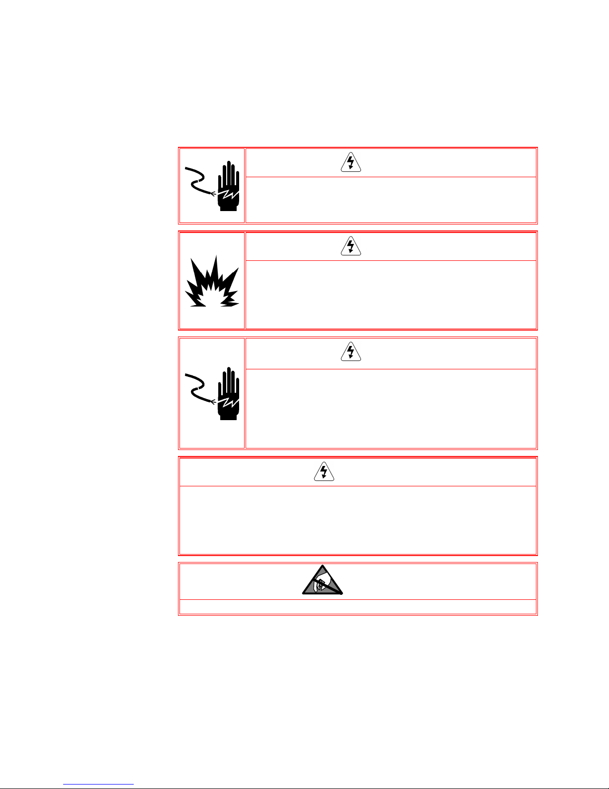
PRECAUTIONS
• READ this manual BEFORE operating or servicing this equipment and FOLLOW
these instructions carefully.
• SAVE this manual for future reference.
FOR CONTINUED PROTECTION AGAINST SHOCK HAZARD CONNECT TO
PROPERLY GROUNDED OUTLET ONLY. DO NOT REMOVE THE GROUND
PRONG.
WARNING!
WARNING!
NOT ALL VERSIONS OF THE IND560 ARE DESIGNED FOR USE IN
HAZARDOUS (EXPLOSIVE) AREAS. REFER TO THE DATA PLATE OF THE
IND560 TO DETERMINE IF A SPECIFIC TERMINAL IS APPROVED FOR USE
IN AN AREA CLASSIFIED AS HAZARDOUS BECAUSE OF COMBUSTIBLE OR
EXPLOSIVE ATMOSPHERES.
WARNING!
WHEN THIS EQUIPMENT IS INCLUDED AS A COMPONENT PART OF A
SYSTEM, THE RESULTING DESIGN MUST BE REVIEWED BY QUALIFIED
PERSONNEL WHO ARE FAMILIAR WITH THE CONSTRUCTION AND
OPERATION OF ALL COMPONENTS IN THE SYSTEM AND THE POTENTIAL
HAZARDS INVOLVED. FAILURE TO OBSERVE THIS PRECAUTION COULD
RESULT IN BODILY HARM AND/OR PROPERTY DAMAGE.
CAUTION
BEFORE CONNECTING/DISCONNECTING ANY INTERNAL ELECTRONIC COMPONENTS OR
INTERCONNECTING WIRING BETWEEN ELECTRONIC EQUIPMENT ALWAYS REMOVE POWER
AND WAIT AT LEAST THIRTY (30) SECONDS BEFORE ANY CONNECTIONS OR
DISCONNECTIONS ARE MADE. FAILURE TO OBSERVE THESE PRECAUTIONS COULD RESULT
IN DAMAGE TO OR DESTRUCTION OF THE EQUIPMENT AND/OR BODILY HARM.
CAUTION
OBSERVE PRECAUTIONS FOR HANDLING ELECTROSTATIC SENSITIVE DEVICES.

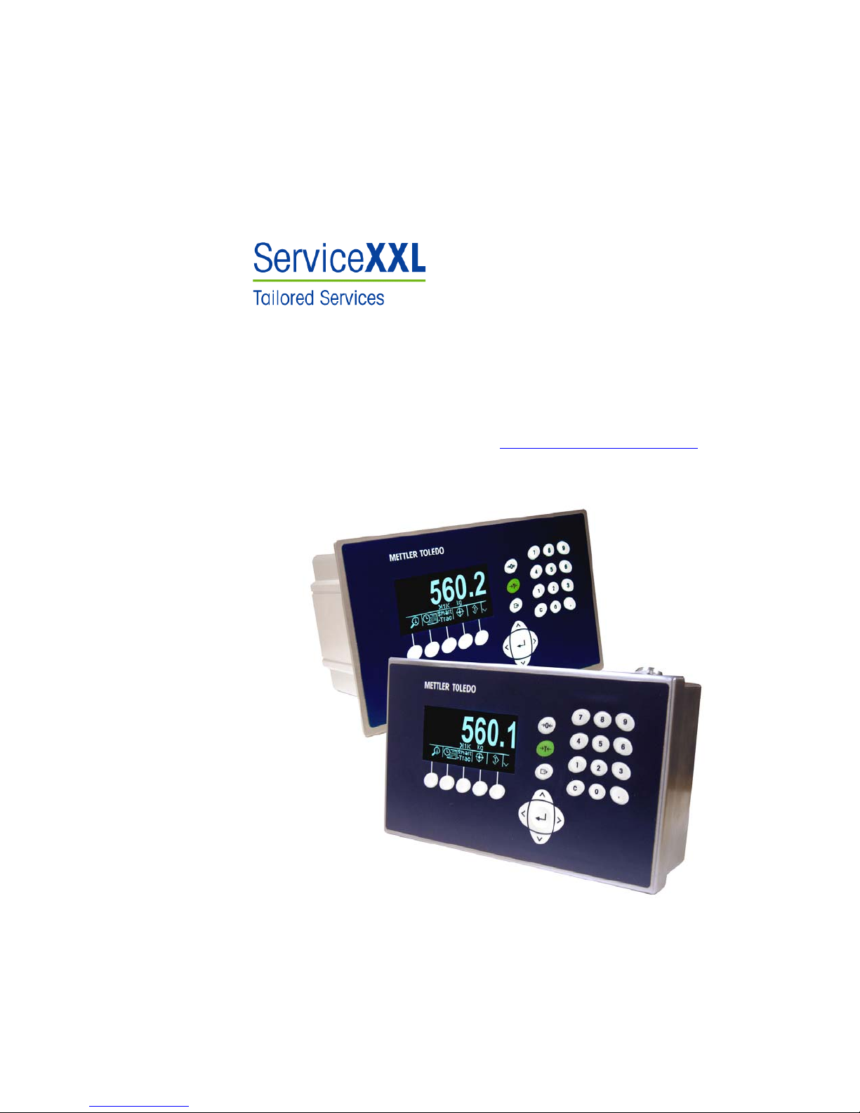
IND560
Terminal
Congratulations on choosing the quality and precision of METTLER TOLEDO.
Proper use according to this Manual and regular calibration and maintenance by
our factory-trained service team ensures dependable and accurate operation,
protecting your investment. Contact us about a ServiceXXL agreement tailored to
your needs and budget.
We invite you to register your product at
can contact you about enhancements, updates and important notifications
concerning your product.
Hwww.mt.com/productregistration so we


IND560 Technical Manual
Contents
Chapter 1.0 Introduction .................................................... 1-1
IND560 Overview....................................................................... 1-2
IND560 Terminal Versions .......................................................... 1-3
Specifications ............................................................................1-3
Environmental Protection............................................................. 1-5
Safe Disposal Requirement.......................................................... 1-5
Inspection and Contents Checklist ................................................1-5
Model Identification .................................................................... 1-6
Physical Dimensions .................................................................. 1-7
Main PCB.................................................................................. 1-9
Scale Bases............................................................................... 1-9
Options..................................................................................... 1-9
Discrete I/O..................................................................................1-10
Ethernet/Serial Ports......................................................................1-10
PLC Interfaces ..............................................................................1-10
Application Software .....................................................................1-11
™
InSite
Configuration Tool..............................................................1-12
Display and Keyboard .............................................................. 1-12
Display Layout .............................................................................1-12
Front Panel Keys ..........................................................................1-13
Chapter 2.0 Operation ....................................................... 2-1
Overview................................................................................... 2-1
Security.........................................................................................2-1
Display Operation....................................................................... 2-3
Softkeys and Icons .........................................................................2-3
Understanding the Navigational Interface....................................... 2-6
Home Screen........................................................................... 2-12
Basic Functionality ................................................................... 2-12
Tare............................................................................................2-13
Unit Switching ..............................................................................2-18
Expand By 10..............................................................................2-18
Print............................................................................................2-19
MinWeigh....................................................................................2-19
Information Recall ........................................................................2-20
Target Comparison .......................................................................2-20
Comparators................................................................................2-26
ID ............................................................................................2-27
SmartTrac
™
..................................................................................2-27

IND560 Technical Manual
Time and Date .............................................................................2-31
Reports .......................................................................................2-31
Calibration Test ............................................................................2-33
Alibi Memory Direct Access........................................................ 2-34
Table Searches ........................................................................2-34
Chapter 3.0 Configuration .................................................. 3-1
Entering Setup Mode................................................................... 3-1
Exiting Setup Mode..................................................................... 3-2
Setup Menu Tree ........................................................................3-2
Setup Screens ................................................................................3-3
Overview of Configuration............................................................ 3-5
Configuration Options ................................................................. 3-7
Scale ............................................................................................3-7
Application ..................................................................................3-24
Terminal......................................................................................3-36
Communication............................................................................3-43
Maintenance ................................................................................3-62
Restoring Factory Default Settings............................................... 3-71
Chapter 4.0 Service and Maintenance................................. 4-1
Cleaning and Maintenance .......................................................... 4-1
Service...................................................................................... 4-1
Upgrading Firmware ................................................................... 4-2
Performing the Upgrade...................................................................4-2
Upgrading to Firmware Version 2.00 ................................................4-3
Changing Screen Saver Graphic ................................................... 4-3
Display Messages ...................................................................... 4-3
Troubleshooting ......................................................................... 4-4
AC Power Test................................................................................4-5
Power Supply Voltage Test...............................................................4-5
Battery Test....................................................................................4-6
Internal Diagnostic Testing...............................................................4-6
RS-232 Serial Output Voltage Test ....................................................4-9
Master Reset ..................................................................................4-9
External Diagnostics ................................................................. 4-11
View Pages..................................................................................4-12
Diagnostics & Maintenance Pages .................................................4-16
Chapter 5.0 Parts and Accessories....................................... 5-1
IND560 Terminal Harsh Enclosure ...............................................5-1
IND560 Terminal Panel-Mount Enclosure...................................... 5-3

IND560 Technical Manual
Appendix A Installation...................................................... A-1
Opening the Enclosures .............................................................. A-1
Panel-Mount Enclosure ................................................................... A-1
Harsh Enclosure............................................................................. A-2
Environmental Protection............................................................. A-2
Mounting the Terminal ................................................................ A-3
Panel-Mount Enclosure ................................................................... A-3
Harsh Enclosure............................................................................. A-4
Installing Cables and Connectors ................................................. A-7
Ferrites..........................................................................................A-7
Harsh Enclosure Cable Glands......................................................... A-8
Main Board Wiring Connections ....................................................... A-9
Wiring Connections for Options ...................................................... A-15
PCB Switch Settings.................................................................. A-25
Main PCB Switches....................................................................... A-25
Discrete I/O (Relay) Switch ............................................................A-26
PCB Jumper Positions .............................................................. A-27
Main PCB Jumper ........................................................................A-27
Capacity Label Instructions........................................................ A-28
Sealing the Enclosure ............................................................... A-29
External Sealing of the Panel-Mount Enclosure................................. A-29
External Sealing of the Harsh Enclosure .......................................... A-30
Internal Sealing of Both Enclosure Types ......................................... A-31
Appendix B Default Settings ............................................... B-1
Setup Defaults................................................................................B-1
Default Templates.........................................................................B-10
Appendix C Table and Log File Structure.............................. C-1
Alibi Memory .............................................................................C-1
Viewing Alibi Memory Records .........................................................C-1
Tare Table ................................................................................. C-3
Selecting From a List.......................................................................C-4
Quick Access .................................................................................C-5
Clearing Totals ...............................................................................C-5
Target Table............................................................................... C-6
Selecting From a List.......................................................................C-7
Quick Access .................................................................................C-8
Change Log File......................................................................... C-8
Maintenance Log File................................................................ C-10
Viewing Change Log File Records.....................................................C-9
Resetting the Log File ....................................................................C-10

IND560 Technical Manual
Viewing Maintenance Log File Records............................................ C-11
Resetting the Log File ....................................................................C-12
Table Reports........................................................................... C-12
Appendix D Communications ............................................. D-1
Serial Interface Parameters ..........................................................D-1
Demand Output Mode................................................................. D-2
Custom Triggers .............................................................................D-2
Output Templates ...........................................................................D-3
Continuous Output Mode............................................................. D-5
Standard Continuous Output ............................................................D-5
Continuous Template Output ............................................................D-7
CTPZ ........................................................................................D-8
Standard Interface Command Set (SICS) Protocol........................... D-8
Data Interface Configuration.............................................................D-8
Version Number of the MT-SICS........................................................D-9
Command Formats.........................................................................D-9
Response Formats..........................................................................D-9
Tips for the Programmer................................................................D-11
Commands and Responses MT-SICS Level 0...................................D-11
Commands and Responses MT-SICS Level 1...................................D-17
Remote Discrete I/O (ARM100).................................................. D-19
ASCII Input...............................................................................D-21
Reports ...................................................................................D-22
Alibi Table ...................................................................................D-22
Tare Table Report .........................................................................D-22
Target Table Report.......................................................................D-23
Message Table Report...................................................................D-24
Totals Report................................................................................D-25
Shared Data Access.................................................................. D-25
Shared Data Server Login ..............................................................D-25
Shared Data Server Commands......................................................D-27
Ethernet ..................................................................................D-33
Ethernet Connection to a PC...........................................................D-33
Ethernet Demand Output................................................................D-36
Ethernet Continuous Output............................................................D-38
FTP ........................................................................................D-39
FTP Example................................................................................D-40
Terminal Updates ..................................................................... D-42
Uploading New Firmware ..............................................................D-42
Uploading Customized Softkey Graphics .........................................D-42

IND560 Technical Manual
Appendix E Softkey Mapping.............................................. E-1
Introduction ............................................................................... E-1
Softkey Setup and Navigation....................................................... E-1
Softkey Configuration .................................................................. E-2
Editing Softkeys.............................................................................. E-3
Inserting Softkeys ...........................................................................E-4
Deleting Softkeys ............................................................................E-4
Clearing All Softkeys .......................................................................E-5
Customizing Softkeys.................................................................. E-5
Appendix F GEO Codes ..............................................................F-1
Original Site Calibration............................................................... F-1
New Site GEO Code Adjustment.................................................... F-1
Appendix G ASCII Standard and Control Characters............... G-1


play
Chapter 1.0
Introduction
This chapter covers
• IND560 Overview
• IND560 Terminal Versions
• Specifications
• Safe Disposal Requirement
• Model Identification
• Physical Dimensions
• Options and Interfaces
• Dis
and Keyboard
Enhance measurement or control applications with an ultra-fast A/D conversion
rate of 366 Hz, patented TraxDSP™ digital filtering technology, and an I/O bus
update rate of 50 Hz. The IND560 delivers precision measurement data from
milligrams to tons in a single cost effective package that easily integrates into
existing systems.
The versatile IND560 excels in controlling filling and dosing applications delivering
best-in-class performance for fast, precise, accurate results in manual,
semi-automatic, or fully automatic operations.
The IND560 represents the latest in METTLER TOLEDO technology
and is the most versatile weighing terminal available today. Choose
from conventional strain gauge or high-precision electromagnetic
force restoration weighing technologies. Specify direct PLC or PC
communication interfaces or digital I/O control. Combine these
selections with the option of panel or desk/wall/column-mounting,
and the IND560 is the perfect match for nearly any weighing
application in many industries, including:
• Basic Weighing • Blending and Batching
• General Process Weighing • Formulation
• Filling • Over/Under Checkweighing
The IND560 promotes more cost-effective solutions too. Control up to 18 digital
outputs through the IND560 without the use of a PLC. Target outputs are also
latched, eliminating the need for external logic devices.
For more advanced filling, the Fill-560 Application Software adds additional
sequences and component inputs. Without complex and costly programming,
quickly configure standard filling sequences or create custom filling and blending
applications for up to four components that cue operators for action and reduce
errors.
Whether communicating weight data to a process PLC or providing an easier way
to do terminal configuration via the InSite™ PC Tool, the IND560 offers multiple
connectivity options to improve applications.
Direct PLC connectivity is available using 4-20mA Analog Output, Allen-Bradley
RIO, PROFIBUS L2 DP or DeviceNet protocols. Interfaces are also available for
serial data via RS-232/422/485 and Ethernet TCP/IP networking.
For information about IND560 terminal operation, refer to the IND560 User Guide.
1-1

IND560 Technical Manual
IND560 Overview
Standard IND560 Features
• Basic weighing terminal used in safe areas
• Panel-mount or harsh desk/wall-mount enclosures
• Connect one analog load cell scale base (or up to eight 350 ohm load
cells) or an IDNet base depending upon the version of the IND560
• 128 × 64 dot-matrix graphic vacuum fluorescent display (VFD) with
21mm-high weight display
• Real-time clock (battery backup)
• One serial port for asynchronous, bidirectional communication and print
output
• 85–264 VAC power input range
• Support for the following option boards:
Analog Output interface
Ethernet and dual serial ports
Allen Bradley RIO
DeviceNet™
PROFIBUS
Discrete I/O interface
• Basic weighing functions including zero, tare, and printing
®
interface
®
L2DP interface
• Selectable over/under classifying mode of operation with graphics
• Selectable material transfer mode for simple filling or dosing
• ID mode for prompted transaction sequencing
• Comparators, simple targets for comparison of weight or rate with target
values or ranges
• SmartTrac™ graphical display
• Two memory tables—25 tare memories and 25 target memories
• Unit switching between three different units including custom units
• Alibi memory storage for up to 60,000 records
• Grand total and subtotal registers for accumulating weight
• Five customizable print templates and report printing
• TraxDSP™ digital filtering for analog load cells
• TraxEMT™ performance monitoring and recording
• CalFREE™ calibration without test weights
1-2
IND560 Terminal Versions
The IND560 terminal is available in the following versions:
• Harsh enclosure with analog load cell connection
• Harsh enclosure with high-precision (IDNet) base connection
• Panel-mount enclosure with analog load cell connection
• Panel-mount enclosure with high-precision (IDNet) base connection
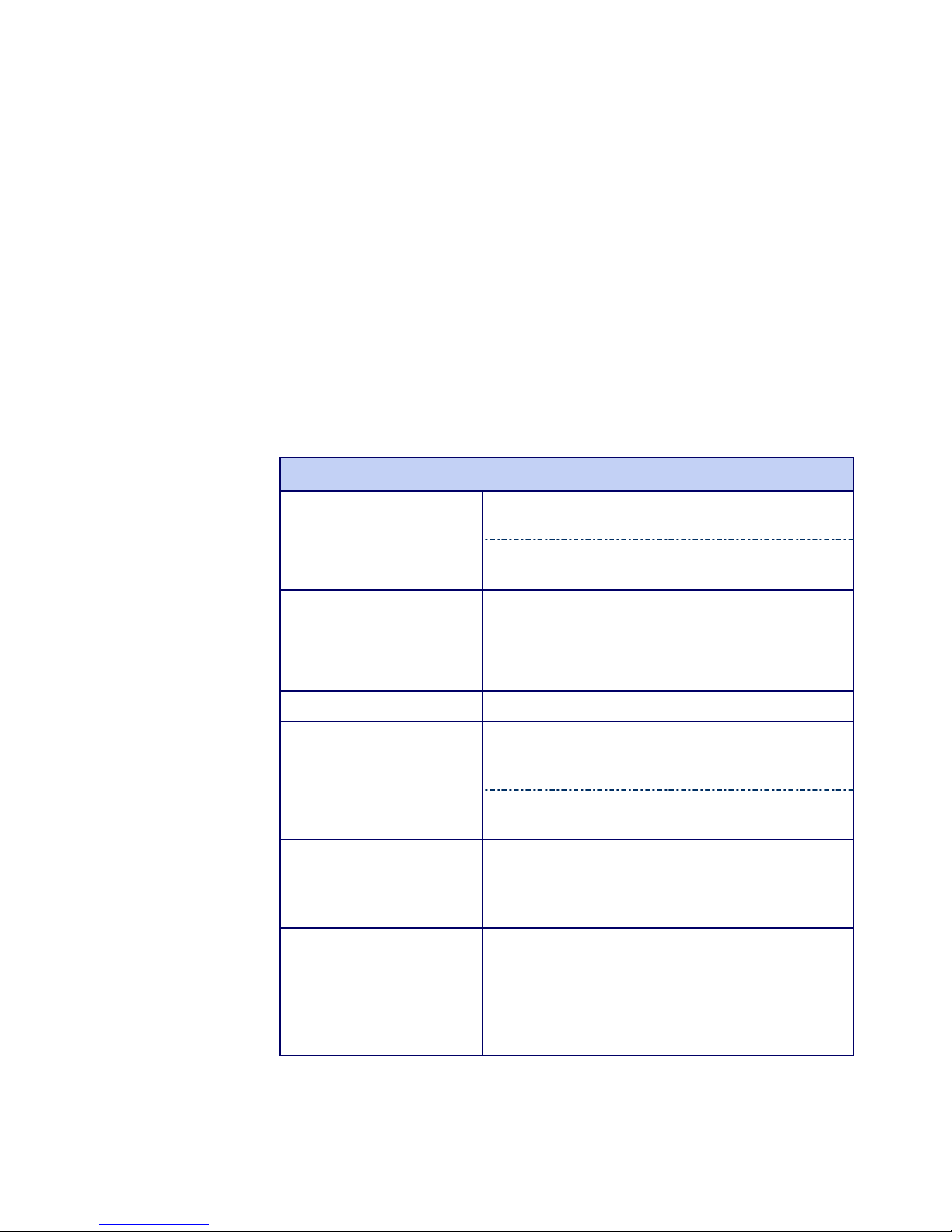
Specifications
The IND560 terminal conforms to the specifications listed in HTable 1-1.
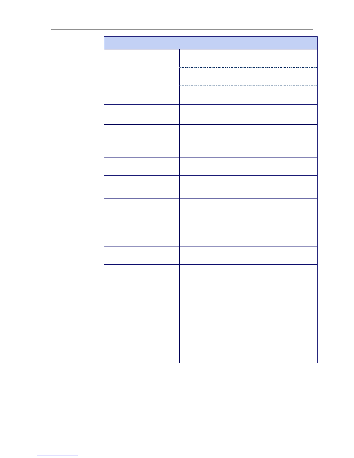
Table 1-1: IND560 Specifications
IND560 Specifications
IND560 Technical Manual
Enclosure Type
Dimensions (l × w × d)
Shipping Weight 3.5 kg (8 lb)
Environmental Protection
Operating Environment The terminal (both enclosure types) can be operated at
Hazardous Areas Not all versions of the IND560 can be operated in areas
Panel-mount stainless steel front panel with an
aluminum frame
Harsh environment desk/wall/column-mount type 304L
stainless steel enclosure
Panel Mount: 265 mm × 160 mm × 92 mm
(10.4 in. × 6.3 in. × 3.6 in.)
Harsh Environment: 265 mm × 160 mm × 170 mm
(10.4 in. × 6.3 in. × 6.7 in.)
Panel-mount front panel sealing is UL-approved, and
provides type 4x and type 12 protection – comparable
to IP65 rating
Harsh Environment is UL-approved, and meets IP69K
requirements
temperatures ranging from −10° to 40° C (14° to
104° F) at 10% to 95% relative humidity noncondensing.
classified as Hazardous by the National Electrical Code
(NEC) because of the combustible or explosive
atmospheres in those areas. Contact an authorized
METTLER TOLEDO representative for information about
hazardous applications.
1-3
IND560 Technical Manual
IND560 Specifications
Power
Operates at 85–264 VAC, 49–61 Hz, 750 mA (both
enclosure types).
Panel-mount version provides a terminal strip for AC
power connections.
Harsh environment version includes a power cord
configured for the country of use.
Display
128 × 64 dot-matrix graphic VFD display, 21 mm
Display Update Rate: 10/second
Weight Display Displayed resolution of 100,000 counts for analog load
cell scales
Display resolution for high-precision IDNet bases is
determined by the specific base used
Scale Types Analog load cells or
IDNet, High-Precision K Line (T-Brick type standard)
Number of Cells Eight 350-ohm load cells (2 or 3 mv/V)
Number of Scales Interface for one analog or one IDNet scale
Analog/Digital Update Rates Internal: Analog: >366 Hz; IDNet: determined by base;
Target Comparison: 50 Hz;
PLC Interface: 20 Hz
Load Cell Excitation Voltage 10 VDC
Minimum Sensitivity 0.1 microvolts
Keypad 25 keys; 1.22-mm thick polyester overlay (PET) with
polycarbonate display lens
Communications
Serial Interfaces
Standard: One serial port (COM1)
RS-232/RS-422/RS-485, 300 to 115,200 baud
Optional Ethernet/Serial Ports: Ethernet 10 Base-T with
two additional serial ports (COM2 and COM3)
Protocol
Serial Inputs: ASCII characters, ASCII commands for
CTPZ (Clear, Tare, Print, Zero), SICS (most level 0 and
level 1 commands)
Serial Outputs: Continuous or Demand with up to five
configurable print templates or SICS host protocol, report
printing, interfaces with external ARM100 Input/Output
modules and DeviceNet Bridge
1-4
IND560 Specifications
IND560 Technical Manual
Approvals
Weights and Measures
USA: NTEP Class II, 100,000 d; Class III/IIIL,
10,000 d, CoC #05-057
Canada: Class III, 10,000 d, approval pending
Europe: OIML;
Class II, approved divisions determined by platform
Class III, 7,500 e
Product Safety
UL, cUL, CE
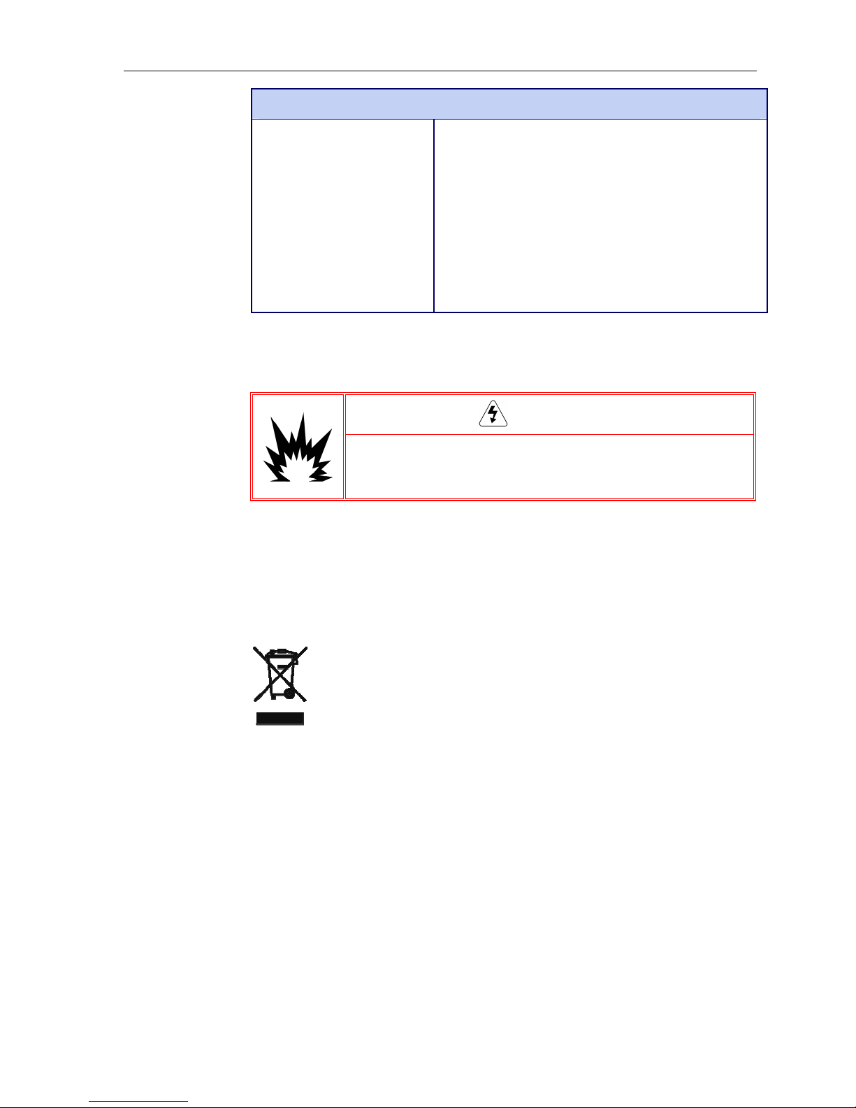
Environmental Protection
THE STANDARD IND560 IS NOT INTRINSICALLY SAFE! DO NOT USE IN
AREAS CLASSIFIED AS HAZARDOUS BY THE NATIONAL ELECTRICAL
CODE (NEC) BECAUSE OF COMBUSTIBLE OR EXPLOSIVE ATMOSPHERES.
WARNING!
Safe Disposal Requirement
In conformance with the European Directive 2002/96/EC on Waste Electrical
and Electronic Equipment (WEEE) this device may not be disposed of in
domestic waste. This also applies to countries outside the EU, per their
specific requirements.
Please dispose of this product in accordance with local regulations at the
collecting point specified for electrical and electronic equipment.
If you have any questions, please contact the responsible authority or the
distributor from which you purchased this device.
Should this device be passed on to other parties (for private or professional
use), the content of this regulation must also be related.
Thank you for your contribution to environmental protection.
Inspection and Contents Checklist
Verify the contents and inspect the package immediately upon delivery. If the
shipping container is damaged, check for internal damage and file a freight claim
with the carrier if necessary. If the container is not damaged, remove the IND560
terminal from its protective package, noting how it was packed, and inspect each
component for damage.
1-5
IND560 Technical Manual
If shipping the terminal is required, it is best to use the original shipping container.
The IND5680 terminal must be packed correctly to ensure its safe transportation.
The package should include:
⎯ IND560 Terminal
⎯ Installation manual
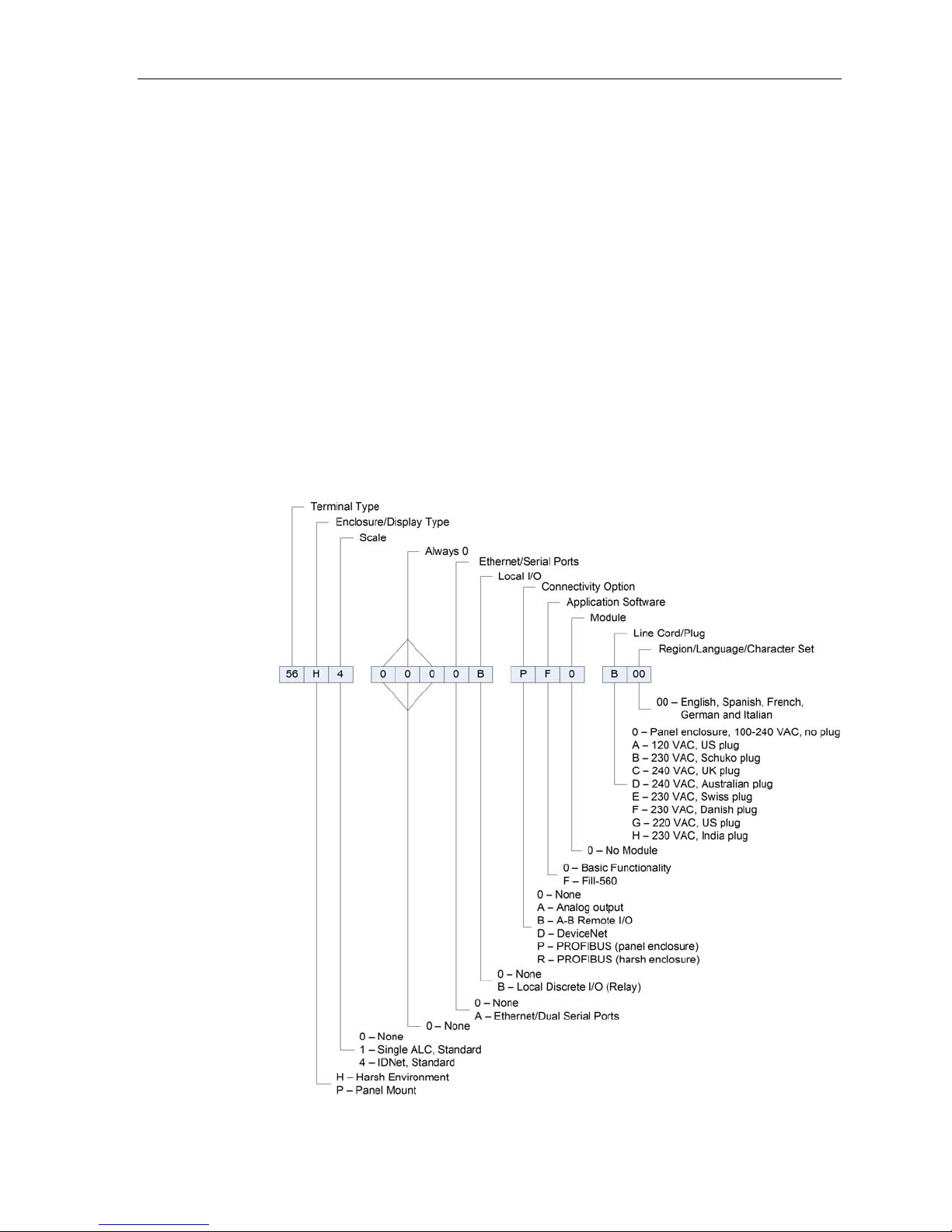
Model Identification
The IND560 model number is located on the data plate on the back of the terminal
along with the serial number. Refer to
ordered.
⎯ Documentation CD
(includes all manuals)
⎯ Bag of parts including
ferrites, grommets, etc.,
depending on terminal
configuration
HFigure 1-1 to verify the IND560 that was
1-6
Figure 1-1: IND560 Model Identification Numbers
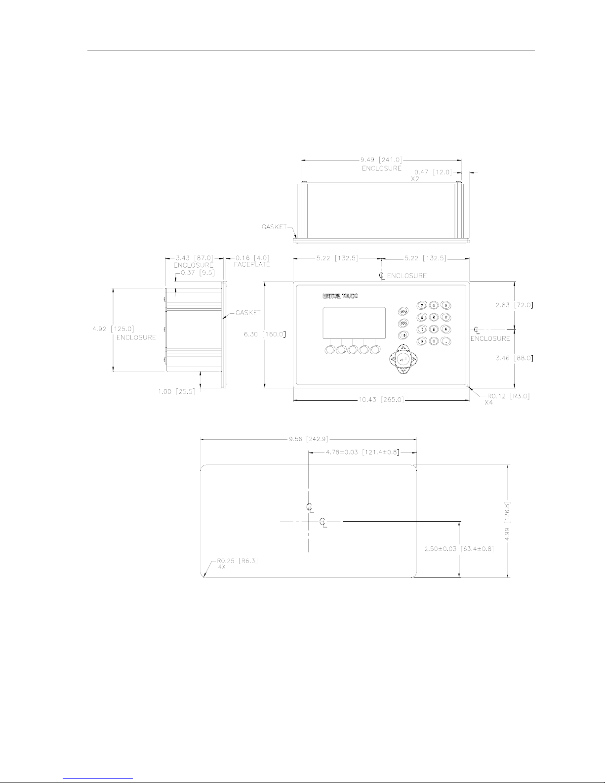
Physical Dimensions
The physical dimensions of the Panel Mount IND560 enclosure are shown in
HFigure 1-2 in inches and [mm]. HFigure 1-3 shows the dimensions of the cutout
required for the Panel Mount enclosure.
IND560 Technical Manual
Figure 1-2: IND560 Panel Mount Enclosure Dimensions
Figure 1-3: IND560 Panel Mount Cutout Dimensions
1-7

IND560 Technical Manual
The dimensions of the harsh enclosure desk/wall-mount IND560 terminal are
shown in
HFigure 1-4 and HFigure 1-5 in inches and [mm].
Figure 1-4: Harsh Environment Enclosure Dimensions
Figure 1-5: Harsh Environment Enclosure Dimensions with Optional Brackets
1-8

Main PCB
The IND560 terminal’s main printed circuit board (PCB) provides the scale
interface for analog load cell or IDNet.
The main board also contains the COM1 serial port that provides RS-232, RS-422,
or RS-485 communication. The port is bidirectional and can be configured for
various functions such as demand output, SICS host communications, continuous
output, ASCII command input (C, T, P, Z), ASCII character input, report printing,
totals printing, or connection to a remote ARM100 module.
The main board also contains the AC power input connections, keyboard interface
and bus connectors for the option boards.
Scale Bases
The IND560 supports two types of scale bases: Analog or IDNet.
IND560 Technical Manual
Options
Analog Load Cell Scale Base
The IND560 supports this scale type by an analog load cell interface. The terminal
can drive up to eight 350-ohm analog load cells.
IDNet™ Scale Base
The IND560 supports the newer T-brick style of high-precision base through the
main board IDNet port. This port provides the +12 volts and communication
required to operate this newer style base. The older K module and Pik-brick cells
require the addition of an adapter board and new power supply (to support the
+32 volt requirement) to the IND560. The adapter board and power supply are
available as an option.
The following options are available for the IND560:
• Discrete I/O
Internal, high-level discrete I/O (4 inputs and 6 outputs)
Remote discrete I/O via ARM100 module
•
Ethernet/Dual Serial Ports
• Programmable Logic Control (PLC) interfaces, including:
•
Fill-560 (application software)
Analog Output
Allen-Bradley
®
(A-B) RIO
DeviceNet™
PROFIBUS
®
L2DP
1-9

IND560 Technical Manual
• Installation kit for older pre-2003 high-precision bases using a PIK-Brick weigh
cell
• InSite™ Configuration Tool
• Various brackets for wall and column mounting of the harsh enclosure
Discrete I/O
The discrete I/O interface options include both internal and remote I/O.
• The internal version is available with dry-contact relay outputs. The relay
contacts will switch up to 30 volts DC or 250 volts AC. The inputs are switch
selectable as either active (for simple pushbutton control) or passive (for
connection to PLCs or other devices that supply their own power for the I/O).
• The remote I/O is supported with the ARM100 remote module that provides dry-
contact outputs. The inputs are passive on the ARM100. An external 24-volt DC
supply is required to operate the ARM100.
• A total of 12 inputs and 18 outputs are supported through a maximum of three
options.
Ethernet/Serial Ports
The Ethernet port can be used for FTP transfer of tare and target tables and
complete setup files. It also provides a TCP/IP port to transmit a demand template,
continuous data, for remote configuration using the METTLER TOLEDO InSite
program, for direct access to data via a shared data server, and to send email
alerts when calibration expires or fails.
COM2 provides RS-232 communication at rates from 300 to 115.2k baud. COM 3
supports the same baud rates and provides an RS-232, RS-422, or RS-485
connection.
™
PLC Interfaces
The IND560 PLC interface options include Analog Output, A-B RIO, DeviceNet and
PROFIBUS L2DP. Additional details about each of these interfaces can be found in
the IND560 PLC Interface Manual, provided on the documentation CD.
Analog Output
Analog Output refers to the representation of an internal system variable using a
proportional electrical signal. Analog Output can be used to transmit a measured
value, such as the gross or net weight. Another use for Analog Output is as a
control signal for some external device, such as a control valve, where the amount
of valve opening is proportional to the analog signal commanding its operation.
Such outputs are used to control the flow rate of material into or out of a vessel.
Both 0-10 volt DC and 4-20 mA signals are provided.
1-10

IND560 Technical Manual
A-B RIO
The A-B RIO option enables data exchange by bi-directional communications using
the Discrete Data Transfer or Block Transfer mode. The IND560 Terminal initiates a
communication exchange with the PLC approximately 20 times per second
utilizing the Allen-Bradley Discrete Data Transfer protocol. This communication is a
high-speed, real-time message interface between the IND560 Terminal and the
PLC for process control. Division, integer, and floating point values are supported.
The IND560 A-B RIO interface also supports Block Transfer mode for transmission
of larger amounts of data.
DeviceNet
DeviceNet is an RS-485 based network utilizing CAN chip technology. This network
was created for bit and byte-level devices. The network can be configured to run up
to 500Kbits per second depending on cabling and distances. Messages are limited
to 8 unfragmented bytes. The network can include up to 64 nodes including the
master, commonly called the scanner.
PROFIBUS L2DP
The IND560 Terminal communicates to a PROFIBUS-DP master according to
DIN 19 245. The PROFIBUS option consists of a module and software that resides
in the IND560 Terminal, which implements the data exchange.
Application Software
Installing Application Software
When a hardware key enabling IND560 application software is installed or
removed, a pop-up message will appear instructing the user to perform a master
reset. The master reset can be performed with or without resetting metrologically
significant EEPROM (scale) data, depending on the positions of switches SW2-1
and SW2-2. Both of these switches must be set to ON in order to reset EEPROM
data to its factory default values. If either of them is set to OFF, EEPROM data is
preserved. Refer to Chapter 4 of this manual, Service and Maintenance, for details
on performing a master reset.
Fill-560
The Fill-560 is a special application that can be added to the IND560 terminal to
provide additional filling and dosing control. It provides control for the following
combinations of weigh-in and weigh-out sequences.
• Fill only • Fill and dose out • Blend and dose out
• Fill and dump • Blend only
• Dose out only • Blend and dump
1-11
IND560 Technical Manual
y
g
App
Additional information can be found in the Fill-560 Manual on the documentation CD.
InSite™ Configuration Tool
The IND560 terminal can connect to a PC running InSite via Ethernet to provide the
following:
• Viewing and/or changing configuration.
• Enabling device-free configuration work before hardware installation.
• Saving configuration information locally on the PC, loading a saved
configuration file into other devices, or restoring to a known state for service
purposes.
• WYSIWYG print template editing tool with expanded viewing area, cut/paste
functions, stored clipboard library (MyData items), and template space usage
display.
• Printing documentation of configuration for users’ records.
• Performing firmware upgrade services for the IND560.
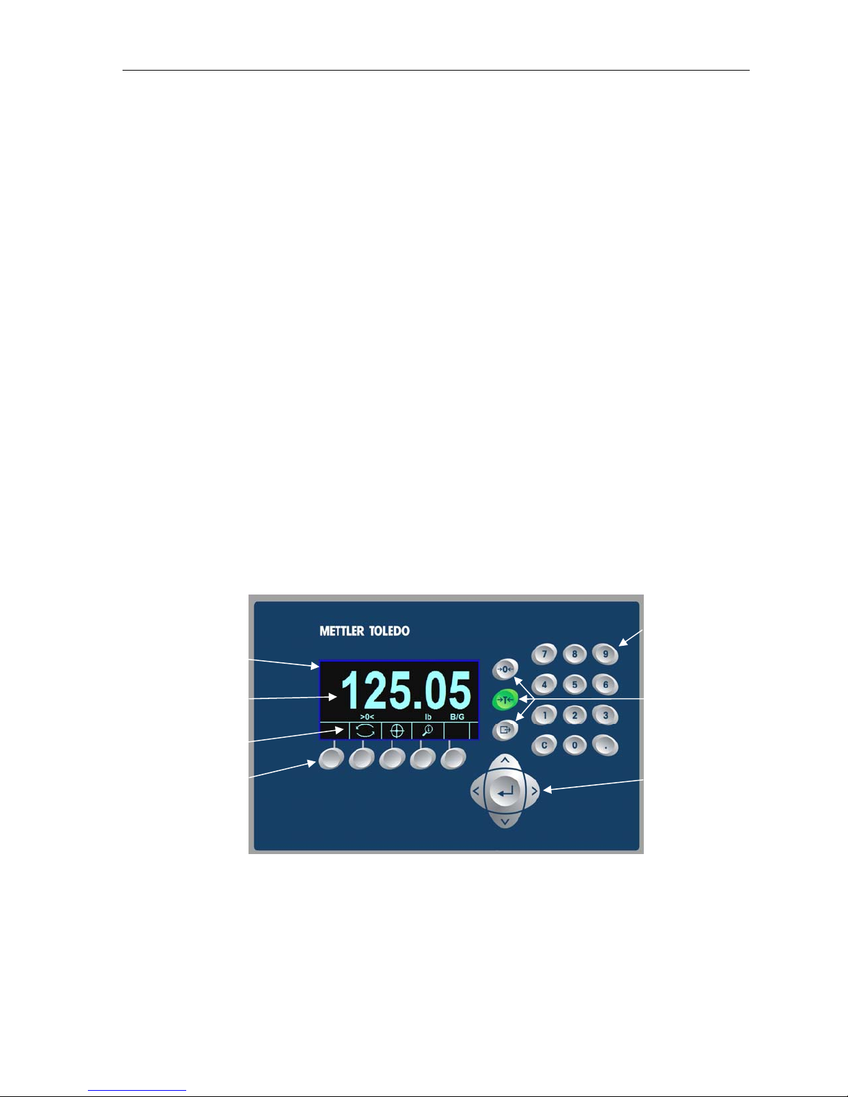
Display and Keyboard
The IND560 terminal has a Vacuum Fluorescent Display (VFD), 128 × 64 dot
matrix graphic type display. An example of the IND560 front panel is shown in
HFigure 1-6.
System line
ht and
Wei
lication area
Softkey labels
s
Softke
Figure 1-6: The IND560 Front Panel Layout
Numeric keys
Zero, Tare, and
Print keys
Navigation keys
Display Layout
• A system line is reserved at the top to show system messages and any
asynchronous errors.
1-12

IND560 Technical Manual
• The middle portion of the display is reserved for the weight display and/or
SmartTrac display. Random data entry is shown in the bottom of this area.
• The bottom of the display is reserved for showing the graphic labels (icons) for
the softkeys. Display positions for up to five softkey icons are provided.
• To the right of the softkey icon area space is reserved for a MORE UP ( ) or a
MORE DOWN (
are available by pressing either the UP or DOWN navigation keys. A total of 15
softkeys, presented in three sets of five, are programmable for the home position
depending upon the weighing options and terminal functions enabled. The softkey
setup and key mapping capabilities of the terminal determine the positioning of the
softkeys and locations where they display.
) indicator. If present, these indicate additional softkey selections
Front Panel Keys
Three dedicated scale function keys are located to the right of the display. These
provide the interface to zero or tare the scale and to initiate a print.
The terminal’s 12-key numeric keypad is used to enter data and commands. The
numeric keys are located on the upper-right side of the terminal front panel.
Five navigation keys are located below the three scale function keys. These keys
enable the operator to navigate through setup options in the menu tree and within
setup and application screens.
1-13

 Loading...