

Mettler Toledo IND310drive User Manual

IND310drive
Terminal
User’s Guide
71207921
(10/05)
R03

© METTLER TOLEDO 2005
No part of this manual may be reproduced or transmitted in any form or by any
means, electronic or mechanical, including photocopying and recording, for any
purpose without the express written permission of METTLER TOLEDO.
U.S. Government Restricted Rights: This documentation is furnished with
Restricted Rights.
Copyright 2005 METTLER TOLEDO. This documentation contains proprietary
information of METTLER TOLEDO. It may not be copied in whole or in part
without the express written consent of METTLER TOLEDO.
METTLER TOLEDO reserves the right to make refinements or changes to the
product or manual without notice.
COPYRIGHT
METTLER TOLEDO® is a registered trademark of METTLER TOLEDO. All other
brand or product names are trademarks or registered trademarks of their
respective companies.

METTLER TOLEDO RESERVES THE RIGHT TO MAKE
REFINEMENTS OR CHANGES WITHOUT NOTICE.
FCC Notice
This device complies with Part 15 of the FCC Rules and the Radio Interference
Requirements of the Canadian Department of Communications. Operation is
subject to the following conditions: (1) this device may not cause harmful
interference, and (2) this device must accept any interference received, including
interference that may cause undesired operation.
This equipment has been tested and found to comply with the limits for a Class
A digital device, pursuant to Part 15 of FCC Rules. These limits are designed to
provide reasonable protection against harmful interference when the equipment
is operated in a commercial environment. This equipment generates, uses, and
can radiate radio frequency energy and, if not installed and used in accordance
with the instruction manual, may cause harmful interference to radio
communications. Operation of this equipment in a residential area is likely to
cause harmful interference in which case the user will be required to correct the
interference at his or her own expense.
Declaration of conformity is located on the documentation CD.
PRECAUTIONS
• READ this manual BEFORE operating or servicing this equipment and FOLLOW
these instructions carefully.
• SAVE this manual for future reference.
FOR CONTINUED PROTECTION AGAINST SHOCK HAZARD CONNECT TO
PROPERLY GROUNDED OUTLET ONLY. DO NOT REMOVE THE GROUND
PRONG.
WARNING!
WARNING!
TO AVOID DAMAGE TO THE PCB OR LOAD CELL, REMOVE POWER FROM THE IND310drive
TERMINAL AND WAIT AT LEAST 30 SECONDS BEFORE CONNECTING OR DISCONNECTING
ANY HARNESS.
CAUTION
BEFORE CONNECTING/DISCONNECTING ANY INTERNAL ELECTRONIC COMPONENTS OR
INTERCONNECTING WIRING BETWEEN ELECTRONIC EQUIPMENT ALWAYS REMOVE POWER
AND WAIT AT LEAST THIRTY (30) SECONDS BEFORE ANY CONNECTIONS OR
DISCONNECTIONS ARE MADE. FAILURE TO OBSERVE THESE PRECAUTIONS COULD RESULT
IN DAMAGE TO OR DESTRUCTION OF THE EQUIPMENT AND/OR BODILY HARM.
CAUTION
OBSERVE PRECAUTIONS FOR HANDLING ELECTROSTATIC SENSITIVE DEVICES.
WARNING!
THE IND310drive TERMINAL IS NOT INTRINSICALLY SAFE! DO NOT USE
WITHIN AREAS CLASSIFIED AS HAZARDOUS DIVISION 1 OR ZONE 0/1
BECAUSE OF COMBUSTIBLE OR EXPLOSIVE ATMOSPHERES.
WARNING!
WHEN THIS EQUIPMENT IS INCLUDED AS A COMPONENT PART OF A
SYSTEM, THE RESULTING DESIGN MUST BE REVIEWED BY QUALIFIED
PERSONNEL WHO ARE FAMILIAR WITH THE CONSTRUCTION AND
OPERATION OF ALL COMPONENTS IN THE SYSTEM AND THE POTENTIAL
HAZARDS INVOLVED. FAILURE TO OBSERVE THIS PRECAUTION COULD
RESULT IN BODILY HARM AND/OR PROPERTY DAMAGE.

Contents
Chapter 1.0 Introduction ..............................................4H1-1
Operating Overview ....................................................................5H1-1
Gross State....................................................................................6H1-1
Net State........................................................................................7H1-2
Operating Modes ............................................................................8H1-2
Weighing Processes .......................................................................9H1-2
Installation and Programming...................................................... 10H1-3
Chapter 2.0 Operating Instructions ..............................11H2-1
Security..................................................................................... 12H2-1
Metrology Switch............................................................................13H2-2
Legal for Trade Settings...................................................................14H2-2
Display Operation....................................................................... 15H2-3
General Navigation.........................................................................16H2-4
Keystroke Functions........................................................................17H2-8
Default Screen.......................................................................... 18H2-11
No Vehicle Application Operation................................................ 19H2-11
Application Operation................................................................ 20H2-11
Direct Entry Option........................................................................21H2-12
Vehicle ID Weighing......................................................................22H2-12
New Vehicle ID.............................................................................23H2-14
Temporary ID Weighing.................................................................24H2-15
Index Weighing............................................................................25H2-17
Transient Vehicle Weighing............................................................26H2-18
Outbound Process........................................................................27H2-19
Inbound Process ..........................................................................28H2-22
Commodity Function.....................................................................29H2-22
Clear and Reset Functions .........................................................
30H2-22
Clearing the Alibi & Transaction Table.............................................31H2-23
Reset ..........................................................................................32H2-23
Table Searches ........................................................................33H2-24
Table Reports...........................................................................
34H2-25
Chapter 3.0 Service and Maintenance.........................35H3-1
Service...................................................................................... 36H3-1
Cleaning and Maintenance ..........................................................
Updating Software ...................................................................... 38H3-2
37H3-1

Appendix A
Basic Weighing Concepts ..........................39HA-1
Zero.......................................................................................... 40HA-1
Tare..........................................................................................
Autotare.........................................................................................42HA-1
Keyboard Tare................................................................................43HA-2
Additive Tare.................................................................................. 44HA-2
Tare Interlocks................................................................................45HA-2
41HA-1
Sections.................................................................................... 46HA-2
Setpoints...................................................................................
Inbound/Outbound Weighing .......................................................
47HA-2
48HA-3
Net Sign Correction..................................................................... 49HA-3
One-Pass Weighing.................................................................... 50HA-3
Appendix B Application Operation Flowcharts ...............51HB-1
Vehicle ID Weighing ...................................................................52HB-3
Temporary ID Weighing ..............................................................53HB-4
Index Weighing..........................................................................54HB-5
Transient Vehicle Weighing.......................................................... 55HB-6

Chapter 1.0
Introduction
This chapter covers
• Operating Overview
• Installation and Programming
The IND310drive Industrial Scale Terminal incorporates the latest
design innovations in vehicle weighing applications. The terminal
contains functionality not available in previous generations of
terminals; it employs a simple setup logic tree that will be carried
across future generations of METTLER TOLEDO terminals.
The simplicity of setup and operation coupled with specific
configurations for multiple applications reduces training costs and
operation setup time. The enhanced software capabilities enable
database storage of key information, which reduces operator error
and time-consuming entries.
Information on installing, programming, and servicing the
IND310drive terminal is located in the IND310drive Installation
Manual and the IND310drive Technical Manual. Review all
instructions and safety precautions carefully. Only authorized
personnel should perform installation and service procedures.
Please contact an authorized METTLER TOLEDO representative to
resolve any questions not covered in this manual or associated
manuals.
Operating Overview
See Appendix A,
Basic Weighing
Concepts for
more information
about basic
weighing
terminology.
To successfully use the IND310drive terminal's various functions, one must
understand
• Basic weighing terminology
• Differences between gross and net states
• The terminal's various operating modes and weighing processes
Gross State
The IND310drive terminal is in the gross state when a tare (the weight of a
container holding the product to be weighed) has not been taken. The full weight of
the items on the scale displays on the terminal.
1-1

IND310drive User Manual
Net State
The IND310drive terminal is in the net state after a tare has been taken. Only the
weight of the items on the scale after the tare is deducted displays, and the net
cursor is lit.
Operating Modes
Routine operations with all vehicle features enabled in setup include four modes of
terminal operation:
• Vehicle ID Weighing—Uses a permanent stored Vehicle ID table to identify the
tare value of the vehicle, and then follows the steps defined by the outbound
process to complete the procedure, which is also called a transaction. Vehicle
ID Weighing enables the accumulation of totals based on vehicle ID.
• Temporary ID Weighing—Coordinates the inbound and outbound processes
for vehicles that are not permanently stored in the Vehicle ID table through the
use of a Temporary ID table. Temporary ID Weighing stores the vehicle
information in the Temporary ID table and follows the inbound process. It also
removes this temporary entry when the vehicle returns and follows the
outbound process. Because the entry is temporary, no accumulation of totals
occurs.
• Index Weighing—Enables the Vehicle ID Weighing mode and Outbound
process to be condensed through the use of a special Index table that provides
a single ID reference for quick multiple ID look-ups.
• Transient Weighing—This mode enables weighing of vehicles that are not
part of normal operation in a manner similar to the Vehicle ID Weighing mode.
Transient Weighing does not use the Vehicle ID table, so the operator must
enter vehicle data. Transient Weighing transactions are not included in any
totals.
Weighing Processes
There are two weighing processes:
• Outbound—Completes the vehicle transaction. The gross, tare, and net weight
values are now known. Other transaction information may be collected (A1–A4
table data, Variable 1, and/or Variable 2 data). The completed transaction
information is stored and can be printed.
• Inbound—Enables the vehicle identification information and a stored weight
value to be collected. Other transaction information may be collected (A1–A4
table data). The inbound transaction information is stored and can be printed.
1-2

Installation and Programming
The IND310drive Installation Manual provides detailed information about
installation. This manual is included in printed format and on a CD with the initial
delivery of the terminal. Installation information for the IND310drive is also
available in the IND310drive Technical Manual, Appendix A.
The IND310drive Technical Manual contains advanced information for
IND310drive setup and programming.
IND310drive User Manual
1-3

IND310drive User Manual
For your notes
1-4

Chapter 2.0
Operating Instructions
This chapter covers
• Security
• Display Operation
• Default Screen
• No Application Operation
• Application Operation
• Clear and Reset Functions
• Table Searches
• Table Reports
Security
The IND310drive supports two levels of users/passwords for setup security:
Administrator and Limited. An administrator-level user can access all setup areas
of the terminal. A limited-access-level user can access all areas of the setup except
for the Scale and Diagnostics blocks.
The IND310drive Terminal is a simple to use, yet sophisticated
terminal with flexibility of configuration to meet a variety operating
requirements. The setup menu system provides the power of
configuration in a user-friendly operational environment.
While reading this manual and operating the terminal, keep in mind
that various functions may or may not be available and that the
screens shown in this manual may vary from terminal-to-terminal
based on the setup configuration.
This User Manual provides instructions for performing typical vehicle
weighing operations on the IND310drive terminal. Detailed
information about terminal configuration and setup is provided in the
IND310drive Technical Manual.
The terminal is pre-configured at the factory with a user name of “ADMIN” and a
user name of “Operator”. The pre-configured users (ADMIN and Operator) cannot
be changed, only the passwords can be added or modified. The factory default
passwords are null (no password). The unit as configured at the factory requires
no login or password entry to enter the setup mode. All functions of the terminal
will be available to all users until a password is entered. Be sure to remember the
password configured for the ADMIN user. If the password is changed or forgotten,
access to the setup menu will not be available. Be sure to protect the password
from access by unauthorized personnel. The password provides access to the
entire setup menu, unless the metrology switch is placed in the approved position.
Ensure that a password has been configured for the ADMIN user prior to
configuring any passwords for other users. Failure to configure the ADMIN user
password before configuring other user passwords could result in being
blocked from access to the entire system.
2-1
IND310drive User Manual
A
p
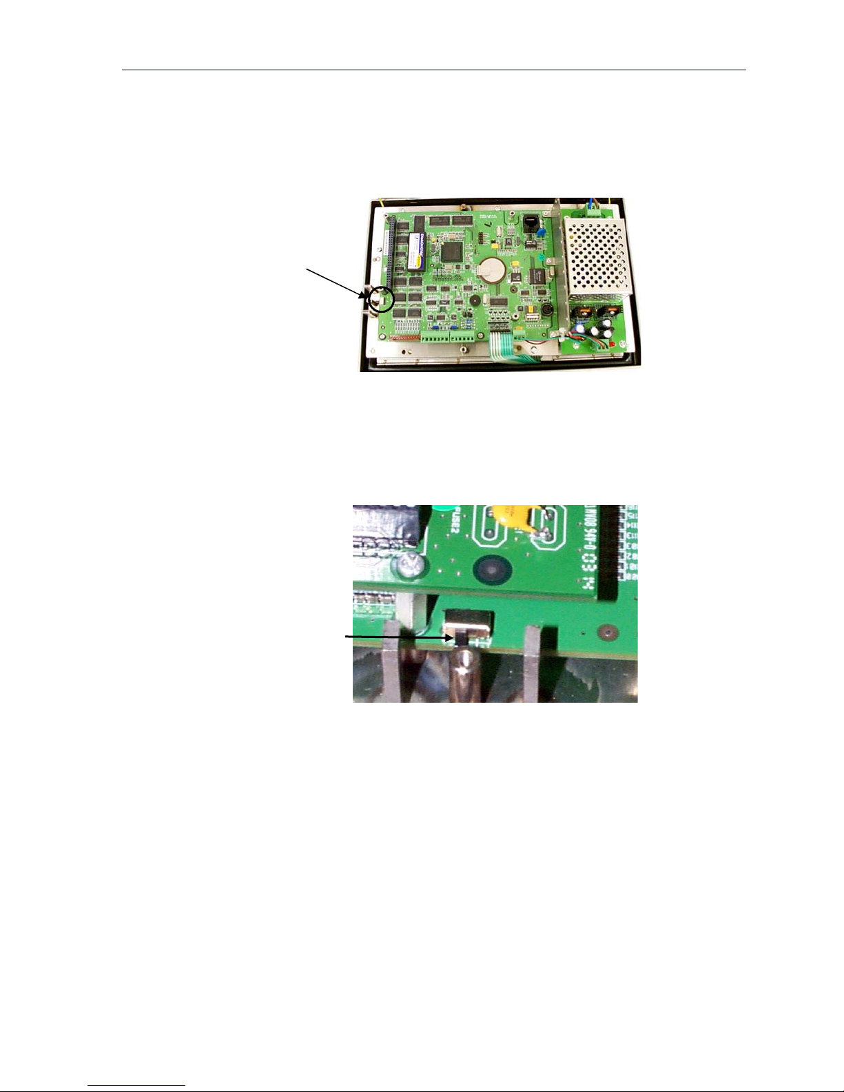
Metrology Switch
The metrology switch (Figure 2-1), which is sealed per Weights and Measures,
controls access to the scale submenu of the setup menu tree. This submenu
includes functions such as calibration, filter settings, tare settings and others.
Metrology switch
The Scale submenu is accessible (may be expanded) only when the Metrology
switch is in the non-approved position. If the metrology switch is in the approved
position (Figure 2-2) the user may enter setup, but will be unable to enter the scale
setup submenu. See the IND310drive Technical Manual for further information
about the metrology switch and accessing the setup menu tree.
Figure 2-1: Metrology Switch Location
pproved
osition
Figure 2-2: Metrology Switch in the Approved Position
Legal for Trade Settings
Legal for Trade settings are accessed through the Scale submenu in the menu tree.
The IND310drive operates within the weights and measurement rules associated
with the Legal for Trade settings. Ensure that the appropriate legal for trade
approval type is selected so that the IND310drive will display weight values in
accordance with specific local weights and measures rules. See the IND310drive
Technical Manual for information on how to change the Legal for Trade settings.
2-2
Display Operation
r
A
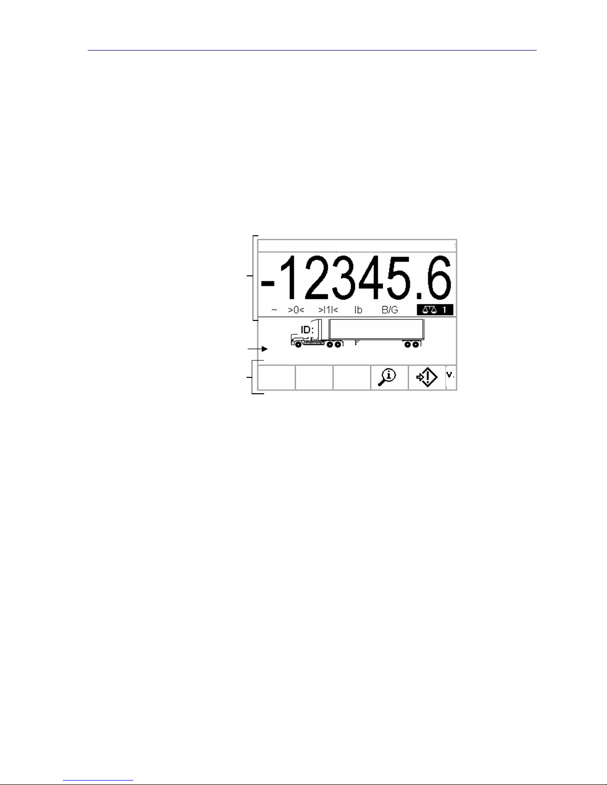
Application operation and setup display screens include the following basic
sections:
• Status bar
• Application area
• Softkeys
IND310drive User Manual
Figure 2-3 shows the location of each of these sections.
09 Jan 2005 08:47:19
Status ba
pplication
area
Softkeys
Figure 2-3: Default Weighing Operation Screen
Status Bar
The status bar shows the terminal's status, including the active scale, weight,
weighing units, date, and time.
Application Area
The application area displays the current application. For example, the application
area shown in Figure 2-3 indicates that a current vehicle ID needs to be entered.
Softkeys
Softkeys are used to select application operation modes. The positioning of
softkeys can be changed and functions enabled or disabled through the softkey
setup page.
2-3

IND310drive User Manual
General Navigation
Navigate in the applications and configure the IND310drive using
• Softkeys • Numeric keys
• Application keys • External Keyboard
• Scale function keys • Alpha keys
• Navigation keys
The locations of the above listed keys and the default weighing operation screen
are shown in Figure 2-4.
Softkeys
The softkey setup page is used to
• Change softkey positions
• Enable softkey functions
• Disable softkey functions
For example, a contrast softkey can be enabled for making quick adjustments to
the terminal screen’s contrast setting.
Five softkeys are located along the bottom of the display screen (see Figure 2-4).
Some screens might have up to three pages of softkeys for a total of 15 possible
functions. A DOWN ARROW icon
screen (to the far right of the softkey icons) indicates that more softkey selections
are available. Press the DOWN arrow navigation key to display additional softkey
screens. Press the UP arrow navigation key to display the previous softkey screen.
displayed on the lower-right corner of the
Default Weighing
Operation Screen
Application (A) Keys
2-4
Scale Function
Keys
Softkeys
Figure 2-4: Key Locations and Default Weighing Operation Screen
Numeric Keys
UP Arrow Navigation Key
Navigation Keys
DOWN Arrow Navigation Key

IND310drive User Manual
Application Keys
Application keys (A keys) are located below the softkeys (see Figure 2-4) and are
labeled
• A1
• A2
• A3
• A4
The application key setup screen is used to assign specific functions to the
application keys. For example, application keys could be configured to magnify the
display ten times, adjust contrast, or select user-defined table information.
Scale Function Keys
Scale function keys (see Figure 2-4) are:
Select Scale—Enables the operator to select a specific scale. Press the
SELECT SCALE key to switch between available scales.
Zero—Zero is the weight of the scale platform or weighbridge when it is
empty. The gross zero reference is recorded during calibration. Press the ZERO
scale function key to capture a new gross zero reference point if pushbutton zero is
enabled in configuration and the weight is within the zero range.
Tare—Tare is the weight of a vehicle when it is empty. Tare is normally
used to determine the net weight of the contents of a vehicle. Press the TARE scale
function key when an empty vehicle is on the scale. The terminal then displays a
zero weight. The vehicle is loaded and driven back onto the scale. The terminal
then displays the net weight of the contents. Pushbutton tare must be enabled to
use this key in this manner.
When the empty weight of the vehicle is a known value, enter the tare weight using
the numeric keys and then press the TARE scale function key. The terminal will
display the net weight of the contents of the vehicle. Keyboard tare must be
enabled in order to use this key in this manner.
Print—Press the PRINT scale function key to generate a hard-copy printout
of a report or of information displayed on the screen or to initiate a demand print of
an assigned print template. A printer must be connected to a serial port and the
terminal must be configured to match its serial port settings to the printer’s.
Communication connection and configuration is necessary to connect a template
or report to the selected serial port, and to define the selected template or report in
configuration.
2-5

IND310drive User Manual
Navigation Keys
Navigation keys (see Figure 2-4) enable navigation within the setup menu tree,
setup screens, and application screens. Navigation keys include:
• Up and down arrows—move the focus up or down to different setup
options within the menu tree or to different fields within setup pages. Focus is
indicated by highlighted text. These keys are also used to switch to another
page of softkeys.
• Left and right arrows—expand (right arrow) or collapse (left arrow)
the setup options in the menu tree. These arrows also move the cursor position
to a specific character in text areas, and enable left and right scrolling to view
all information available on a screen.
Enter—opens the setup page for viewing and editing setup parameters.
•
The Enter key moves the focus from a field label to a setup value for that field.
After entering a value, the enter key is used to accept new values and the focus
moves to the next field label.
Numeric Keys
Use the terminal’s 12-key numeric keypad (see Figure 2-4) to enter data and
commands.
To use numeric keys, position the cursor in the field (see Navigation Keys) and
press the numeric keys to enter the appropriate data. Press the DECIMAL key
(. key) to enter decimal points where necessary.
The CLEAR key (C key) functions like a backspace key. Position the cursor at the
end of data to be deleted and press the C key. Press the C key once for each
character to be deleted.
Alpha Keys
On some setup pages, softkeys and application keys function as alpha keys (see
Figure 2-5) that are used to enter alphabetic characters for setup parameters such
as passwords.
2-6
 Loading...