

Page 1
User's Guide
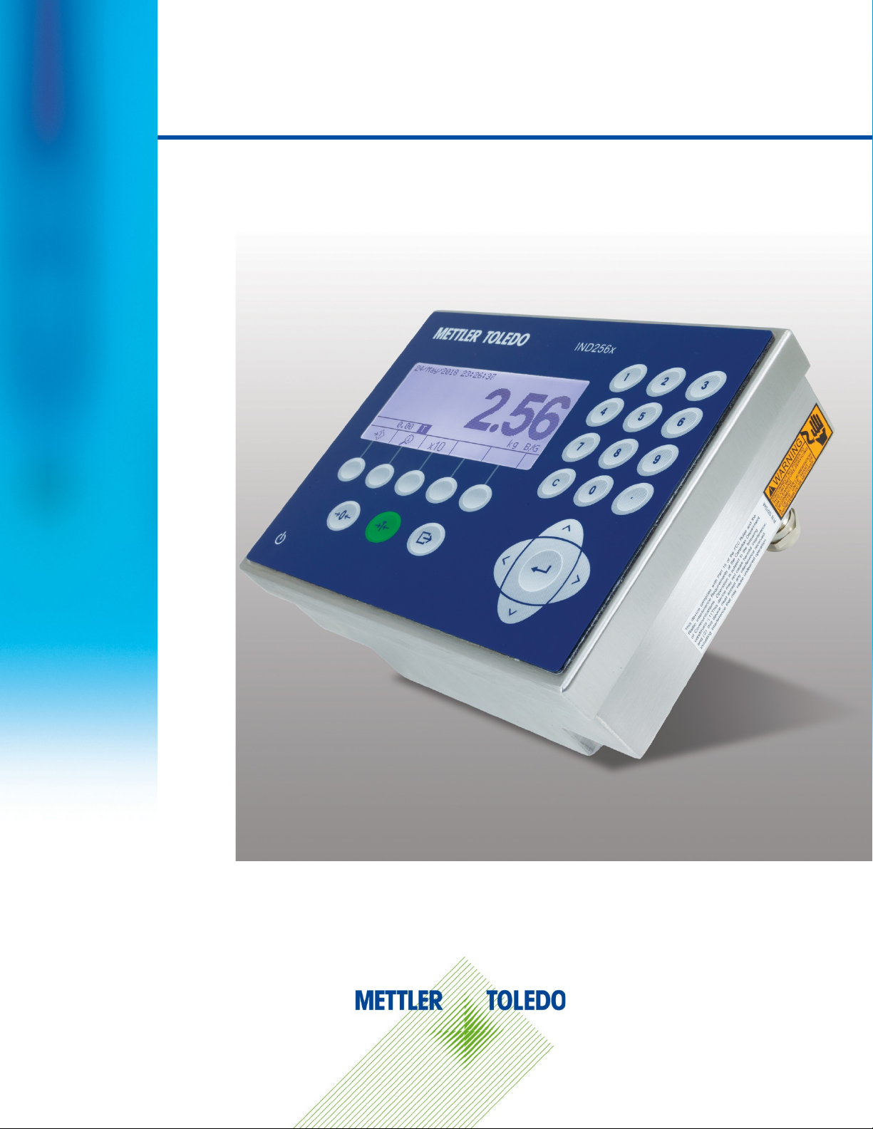
IND256x
Weighing Terminal
Page 2

IND256x Weighing Terminal
Essential Services for Dependable Performance of Your IND256x Weighing Terminal
Congratulations on choosing the quality and precision of METTLER TOLEDO. Proper use of your
new equipment according to this Manual and regular calibration and maintenance by our factorytrained service team ensures dependable and accurate operation, protecting your investment.
Contact us about a service agreement tailored to your needs and budget. Further information is
available at www.mt.com/service
There are several important ways to ensure you maximize the performance of your investment:
1. Register your product: We invite you to register your product at
www.mt.com/productregistration so we can contact you about enhancements, updates and
important notifications concerning your product.
2. Contact METTLER TOLEDO for service: The value of a measurement is proportional to its
accuracy – an out of specification scale can diminish quality, reduce profits and increase
liability. Timely service from METTLER TOLEDO will ensure accuracy and optimize uptime and
equipment life.
.
a. Installation, Configuration, Integration and Training: Our service representatives are factory-
trained, weighing equipment experts. We make certain that your weighing equipment is
ready for production in a cost effective and timely fashion and that personnel are trained for
success.
b. Initial Calibration Documentation: The installation environment and application
requirements are unique for every industrial scale so performance must be tested and
certified. Our calibration services and certificates document accuracy to ensure production
quality and provide a quality system record of performance.
c. Periodic Calibration Maintenance: A Calibration Service Agreement provides on-going
confidence in your weighing process and documentation of compliance with requirements.
We offer a variety of service plans that are scheduled to meet your needs and designed to
fit your budget.
d. GWP® Verification: A risk-based approach for managing weighing equipment allows for
control and improvement of the entire measuring process, which ensures reproducible
product quality and minimizes process costs. GWP (Good Weighing Practice), the sciencebased standard for efficient life-cycle management of weighing equipment, gives clear
answers about how to specify, calibrate and ensure accuracy of weighing equipment,
independent of make or brand.
Page 3

© METTLER TOLEDO 2019
No part of this manual may be reproduced or transmitted in any form or by any means, electronic or
mechanical, including photocopying and recording, for any purpose without the express written
permission of METTLER TOLEDO.
U.S. Government Restricted Rights: This documentation is furnished with Restricted Rights.
Copyright 2019 METTLER TOLEDO. This documentation contains proprietary information of METTLER
TOLEDO. It may not be copied in whole or in part without the express written consent of METTLER
TOLEDO.
METTLER TOLEDO reserves the right to make refinements or changes to the product or manual
without notice.
COPYRIGHT
METTLER TOLEDO® is a registered trademark of Mettler-Toledo, LLC. All other brand or product
names are trademarks or registered trademarks of their respective companies.
METTLER TOLEDO RESERVES THE RIGHT TO MAKE REFINEMENTS OR CHANGES
WITHOUT NOTICE.
FCC Notice
This device complies with Part 15 of the FCC Rules and the Radio Interference Requirements of the
Canadian Department of Communications. Operation is subject to the following conditions: (1) this
device may not cause harmful interference, and (2) this device must accept any interference
received, including interference that may cause undesired operation.
This equipment has been tested and found to comply with the limits for a Class A digital device,
pursuant to Part 15 of FCC Rules. These limits are designed to provide reasonable protection against
harmful interference when the equipment is operated in a commercial environment. This equipment
generates, uses, and can radiate radio frequency energy and, if not installed and used in
accordance with the instruction manual, may cause harmful interference to radio communications.
Operation of this equipment in a residential area is likely to cause harmful interference in which case
the user will be required to correct the interference at his or her expense.
Declaration of Conformity is available at
http://glo.mt.com/global/en/home/search/compliance.html/compliance/
.
Page 4
Warnings and Cautions
• READ this manual BEFORE operating or servicing this equipment and FOLLOW these instructions
carefully.
• SAVE this manual for future reference.
WARNING
DO NOT INSTALL OR PERFORM ANY SERVICE ON THIS EQUIPMENT BEFORE THE AREA IN WHICH THE
IND256x IS LOCATED HAS BEEN SECURED AS NON-HAZARDOUS BY PERSONNEL AUTHORIZED TO DO SO
BY THE RESPONSIBLE PERSON AT THE CUSTOMER’S SITE.
CAUTION
CONFIRM COMPLIANCE WITH APPLICABLE NATIONAL AND LOCAL WIFI REGULATIONS BEFORE INSTALLING
AND COMMISSIONING IND256x TERMINAL CONFIGURED WITH WIFI MODULE. METTLER TOLEDO ACCEPTS
NO RESPONSIBILITY FOR TERMINAL INSTALLATION IN COUNTRIES WHERE WIFI REGULATIONS ARE NOT
FULFILLED.
WARNING
IF THE IND256x KEYBOARD, DISPLAY LENS OR ENCLOSURE IS DAMAGED, THE DEFECTIVE COMPONENT
MUST BE REPLACED IMMEDIATELY. REMOVE POWER IMMEDIATELY AND DO NOT REAPPLY POWER UNTIL
THE DISPLAY LENS, KEYBOARD OR ENCLOSURE HAS BEEN REPAIRED OR REPLACED BY QUALIFIED
SERVICE PERSONNEL. FAILURE TO DO SO COULD RESULT IN BODILY HARM AND/OR PROPERTY DAMAGE.
CAUTION
USE ONLY METTLER TOLEDO SPARE PARTS WHEN REPLACING THE WiFi MODULE. METTLER TOLEDO
ACCEPTS NO RESPONSIBILITY FOR SAFETY OR COMPLIANCE RISKS CAUSED BY USE OF INCORRECT
COMPONENTS.
WARNING
AVOID ELECTROSTATIC CHARGING DURING OPERATION AND MAINTENANCE.
WARNING
OPERATION IS ONLY PERMITTED WHEN OPERATIONAL AND PROCESS-RELATED ELECTROSTATIC CHARGES
ARE NOT PRESENT.
WARNING
USE THE WEIGHING TERMINAL ONLY WHEN ELECTROSTATIC PROCESSES LEADING TO PROPAGATION
BRUSH DISCHARGE IS IMPOSSIBLE.
WARNING
KEEP THE TERMINAL AWAY FROM PROCESSES THAT GENERATE HIGH CHARGING POTENTIAL SUCH AS
ELECTROSTATIC COATING, RAPID TRANSFER OF NON-CONDUCTIVE MATERIALS, RAPID AIR JETS, AND
HIGH PRESSURE AEROSOLS.
Page 5
WARNING
DO NOT USE DRY CLOTH TO CLEAN THE WEIGHING TERMINAL. ALWAYS USE A DAMP CLOTH TO CLEAN
THE TERMINAL GENTLY.
WARNING
WEAR SUITABLE CLOTHING. AVOID NYLON, POLYESTER OR OTHER SYNTHETIC MATERIALS THAT
GENERATE AND HOLD CHARGE. USE CONDUCTIVE FOOTWEAR AND FLOORING.
WARNING
AVOID PLASTIC COVERS OVER THE TERMINAL.
WARNING
ENSURE PROPER EQUIPOTENTIAL GROUNDING OF THE TERMINAL, MOUNTING ACCESSORIES, AND THE
SCALE BASE.
WARNING
Warnings and Cautions
TERMINAL MUST BE PROTECTED FROM UV LIGHT.
WARNING
FOR THE DC VERSION OF THE IND256x TERMINAL, THERE IS NO GALVANIC SEPARATION BETWEEN NONINTRINSICALLY SAFE SUPPLY CIRCUIT AND INTRINSICALLY SAFE OUTPUT CIRCUITS. THE NONINTRINSICALLY SAFE CIRCUIT MUST BE SAFELY CONNECTED TO EARTH. AND POTENTIAL EQUALIZATION
MUST EXIST ALONG INTRINSICALLY SAFE CIRCUITS.
ALTERNATIVELY, THE NON-INTRINSICALLY SAFE SUPPLY CIRCUIT (SELV) MUST BE SAFELY SEPARATED
FROM EARTH.
WARNING
THE EXTERNAL CUSTOMER-PROVIDED DC POWER SUPPLY MUST HAVE A CATEGORY II MAXIMUM OVERVOLTAGE, ACCORDING TO IEC 60664-1.
WARNING
SUFFICIENT STRAIN RELIEF MUST BE ENSURED TO PREVENT TENSILE FORCES ON THE CABLE GLANDS.
WARNING
THE CABLE GLANDS MUST BE PROTECTED AGAINST DAMAGE FROM IMPACT.
WARNING
THE TERMINAL ASSEMBLED WITH WIFI ANTENNA SHALL BE INSTALLED IN A POSITION IN SUCH A WAY
THAT THE RISK FOR MECHANICAL DAMAGE IS LOW. REPLACE THE WIFI ANTENNA IMMEDIATELY IF
DAMAGED.
Page 6
WARNING
IND256x TERMINALS FACTORY-CONFIGURED WITH WIFI ARE APPROVED FOR USE IN ZONE 1 EQUIPMENT
GROUP IIB CLASSIFIED AREAS. IND256x TERMINALS FACTORY-CONFIGURED WITH WIFI MUST NOT BE
USED IN EQUIPMENT GROUP IIC CLASSIFIED AREA. USING THE IND256X TERMINAL FACTORYCONFIGURED WITH WIFI IN A CLASSIFIED AREA FOR WHICH IT IS NOT APPROVED COULD RESULT IN
BODILY HARM AND/OR PROPERTY DAMAGE.
WARNING
THE EXTERNAL CUSTOMER-PROVIDED DC POWER SUPPLY MUST HAVE A MAXIMUM OVER-VOLTAGE
CATEGORY II ACCORDING TO IEC 60664-1.
WARNING
DO NOT OPEN THE TERMINAL WHEN THE ATMOSPHERE IS EXPLOSIVE DUE TO DUST. TO PREVENT
IGNITION OF HAZARDOUS ATMOSPHERES, DISCONNECT THE IND256x FROM ITS POWER SOURCE BEFORE
OPENING THE ENCLOSURE. KEEP COVER TIGHTLY CLOSED WHILE THE CIRCUIT IS ENERGIZED. DO NOT
OPEN WHEN AN EXPLOSIVE DUST ATMOSPHERE IS PRESENT.
WARNING
ALL EQUIPMENT MUST BE INSTALLED PER MANUFACTURER'S DOCUMENT DRAWING NUMBER
30282892B AND APPLICABLE LOCAL CODES.
WARNING
ONLY THE COMPONENTS SPECIFIED IN THE INSTALLATION MANUAL INCLUDED ON THE DOCUMENTATION
CD-ROM 30512916 CAN BE USED IN THIS DEVICE. ALL EQUIPMENT MUST BE INSTALLED IN
ACCORDANCE WITH THE INSTALLATION INSTRUCTIONS. INCORRECT OR SUBSTITUTE COMPONENTS
AND/OR DEVIATION FROM THESE INSTRUCTIONS CAN IMPAIR THE INSTRINSIC SAFETY OF THE TERMINAL
AND COULD RESULT IN BODILY INJURY AND/OR PROPERTY DAMAGE.
WARNING
FOR CONTINUED PROTECTION AGAINST SHOCK HAZARD, CONNECT TO PROPERLY GROUNDED POWER
SOURCE ONLY. DO NOT REMOVE THE GROUNDING CONNECTION.
WARNING
WHEN THIS EQUIPMENT IS INCLUDED AS A COMPONENT PART OF A SYSTEM, THE RESULTING DESIGN
MUST BE REVIEWED BY QUALIFIED PERSONNEL WHO ARE FAMILIAR WITH THE CONSTRUCTION AND
OPERATION OF ALL COMPONENTS IN THE SYSTEM AND THE POTENTIAL HAZARDS INVOLVED. FAILURE TO
OBSERVE THIS PRECAUTION COULD RESULT IN BODILY HARM AND/OR PROPERTY DAMAGE.
WARNING
ONLY PERMIT QUALIFIED PERSONNEL TO SERVICE THE IND256x. EXERCISE CARE WHEN MAKING
CHECKS, TESTS AND ADJUSTMENTS THAT MUST BE MADE WITH POWER ON. FAILING TO OBSERVE THESE
PRECAUTIONS CAN RESULT IN BODILY HARM AND/OR PROPERTY DAMAGE.
Page 7
In conformance with the European Directive 2002/96/EC on Waste Electrical and Electronic
WARNING
BEFORE CONNECTING/DISCONNECTING ANY INTERNAL ELECTRONIC COMPONENTS OR
INTERCONNECTING WIRING BETWEEN ELECTRONIC EQUIPMENT ALWAYS REMOVE POWER AND WAIT AT
LEAST THIRTY (30) SECONDS BEFORE ANY CONNECTIONS OR DISCONNECTIONS ARE MADE. FAILURE TO
OBSERVE THESE PRECAUTIONS COULD RESULT IN DAMAGE TO OR DESTRUCTION OF THE EQUIPMENT
AND/OR BODILY HARM.
NOTICE
OBSERVE PRECAUTIONS FOR HANDLING ELECTROSTATIC SENSITIVE DEVICES.
Disposal of Electrical and Electronic Equipment
Equipment (WEEE) this device may not be disposed of in domestic waste. This also applies to
countries outside the EU, per their specific requirements.
Please dispose of this product in accordance with local regulations at the collecting point specified
for electrical and electronic equipment.
If you have any questions, please contact the responsible authority or the distributor from which you
Warnings and Cautions
purchased this device.
Should this device be passed on to other parties (for private or professional use), the content of this
regulation must also be related.
Thank you for your contribution to environmental protection.
Page 8

30491440 | 02 | 11/2019
METTLER TOLEDO IND256x Weighing Terminal User's Guide
1
Contents
1 Introduction ................................................................................. 1-1
1.1. IND256x Overview ........................................................................ 1-1
1.2. Product Specification ..................................................................... 1-2
1.3. Testing Standards ......................................................................... 1-4
1.4. Warnings and Precautions ............................................................. 1-6
1.5. Inspection and Contents Checklist ................................................... 1-6
1.6. Configuration ................................................................................ 1-7
1.7. Equipotential Bonding (EB) ............................................................ 1-9
1.8. Operating Environment .................................................................. 1-9
1.9. Dimensions ................................................................................ 1-10
1.10. Main Board ................................................................................ 1-12
1.11. Communication Option Boards ..................................................... 1-12
2 Operation .................................................................................... 2-1
2.1. Overview ...................................................................................... 2-1
2.2. Display and Keyboard ................................................................... 2-2
2.3. Data Input .................................................................................... 2-6
2.4. Main Display ................................................................................ 2-7
3 Configuration .............................................................................. 3-1
3.1. Enter Setup ................................................................................... 3-1
3.2. Exit Setup ..................................................................................... 3-2
3.3. Setup Menu .................................................................................. 3-2
3.4. Configuration Overview .................................................................. 3-3
3.5. Scale ........................................................................................... 3-4
3.6. Application ................................................................................. 3-24
3.7. Terminal .................................................................................... 3-33
3.8. Communication .......................................................................... 3-39
3.9. Maintenance .............................................................................. 3-49
4 Service and Maintenance ............................................................. 4-1
4.1. Terminal Cleaning and Maintenance ................................................ 4-1
4.2. Service ........................................................................................ 4-2
4.3. Error Messages ............................................................................. 4-2
4.4. System Information ....................................................................... 4-4
4.5. Firmware Upgrade ......................................................................... 4-5
Page 9

2
METTLER TOLEDO IND256x Weighing Terminal User's Guide
30491440 | 02 | 11/2019
4.6. Backup and Restore Using InSite™ ................................................. 4-5
4.7. Troubleshooting ............................................................................ 4-5
4.8. Master Reset .............................................................................. 4-10
A. Parameter Values ........................................................................ A-1
B. Communication ........................................................................... B-1
B.1. Demand Output Mode.................................................................... B-1
B.2. Continuous Output Mode ................................................................ B-1
Contents
B.3. CTPZ ........................................................................................... B-3
B.4. Standard Interface Command Set (SICS) Protocol .............................. B-4
B.5. Reports ...................................................................................... B-13
B.6. Label Design and Printing ............................................................ B-15
C. GEO Codes .................................................................................. C-1
C.1. Original Site Calibration ................................................................. C-1
C.2. New Site GEO Code Adjustment ...................................................... C-1
Page 10

30491440 | 02 | 11/2019
METTLER TOLEDO IND256x Weighing Terminal User's Guide
1-1
1 Introduction
1.1. IND256x Overview
The IND256x reflects the latest weighing technology from METTLER TOLEDO. The IND256x has
passed third-party certification for weighing in hazardous areas, and can be directly used in Zone
1/Zone 21 locations.
A high-performance single-range or multi-range weighing terminal, the IND256x uses analog load
cells to achieve reliable weighing at low cost, from grams to tons. It is easily integrated in an
existing weighing system.
By connecting the appropriate safety barrier or isolated barrier, the IND256x can provide various
intrinsically safe communication interfaces to communicate with PCs and printers in the safe area.
These features permit IND256x to support a majority of weighing applications in most industrial
fields, including:
• Pharmacy
• Powder processes
• Special chemicals
1.1.1. IND256x Terminal Version
The IND256x is available with three different power supply choices:
• AC power input, using external alternating voltage (187-250 V 50/60 Hz)
• DC power input, using external direct voltage (DC 18-30 V)
• Intrinsically safe power input, using an external Ex NiMH battery pack (64060627)
Each of these versions has received ATEX and IECEx approvals for use in Zone 1 and Zone 21
classified areas.
1.1.2. IND256x Product Features
• Basic weighing in hazardous areas, including zero, tare and print functions
• Harsh environment desk, column- or wall-mounted enclosure
• Connects to a single analog weighing platform
• 240 x 96 pixel white backlit LCD, 25mm high digits
• Petrochemicals
• Agriculture
• Paints and inks
• Fine chemical engineering
• Real-time clock (power-down save)
Page 11
1-2
METTLER TOLEDO IND256x Weighing Terminal User's Guide
30491440 | 02| 11/2019
– Intrinsically safe 4-20 mA analog output
Enclosure
Dimensions h × w × d)
Transport weight
Protection grade
Storage environment
Service environment
• Includes one intrinsically safe serial port (COM1) for asynchronous two-way communication
and print output
• Support for the following internal option boards:
– WiFi communication module with antenna (only in IND256x terminals factory-
configured with WiFi module)
– Active current loop – for connection to an ACM200 communication module located
in the safe area, or to connect second IND256x terminal configured with passive
current loop option
Introduction
– Passive current loop (used as the second display to connect another terminal with
an active current loop)
• Supports three customized ID inputs
• Target table supports 25 pre-set targets for Checkweighing
• Tare table supports 20 pre-set tare values
• Supports g, kg, t, ton, lb and oz
• Saves 60,000 transaction data items
• Supports accumulation and accumulative total
• Permits the customization of five different print templates
• Supports weight-free calibration (CalFREE™)
1.2. Product Specification
Table 1-1 shows the IND256x specifications.
Table 1-1: IND256x Specifications
Item Specification
304 stainless steel, can be wall- or pole-mounted
173 mm × 230 mm × 127 mm
(6.8 in. ×9.1 in. ×5.0 in.)
3.5 kg (8 lb)
IP66
Storage temperature range: –20°C to 60° C (–4° to 140°F)
Relative humidity: 10% to 95%, non-condensing
Operating temperature range: –10°C to 40° C (14° to 104°F)
Relative humidity: 10% to 95%, non-condensing
Page 12
30491440 | 02 | 11/2019
METTLER TOLEDO IND256x Weighing Terminal User's Guide
1-3
Item Specification
Hazardous area
Power supply
Display
Weight display
Weighing platform type
Sensor quantity
Maximum of four 350-ohm load cells (minimum 87 ohm), 2 mv/V or 3
mv/V
Weighing platform quantity
Refresh rate
Sensor excitation voltage
Minimum sensitivity
Keyboard
Communication mode
configurable templates), SICS command and report print
Metrological Approval
Europe: OIML R76; Class III, 6000e; TC10878
Hazardous Area Approval,
factory-configured WiFi version
Hazardous approval
IND256x is approved for use in Zone 1/Zone 21 hazardous areas
AC power (187-253V 50/60Hz)
DC power (CD 18-30 V)
External NiMH Ex battery pack (64060627)
240 x 96 pixel white backlit LCD, 25mm high digits
Display update rate: 10 Hz
Maximum 100,000 divisions
Analog load cell
Supports one weighing platform
>366 Hz
4.5 VDC
0.6µV/e
26 keys; 1.5mm thick membrane keyboard
Standard interface:
The mainboard is provided with an intrinsically safe RS232
communication interface
Interface options:
Intrinsically safe 4-20 mA analog output module, with16-bit D/A
conversion and 25 Hz update rate to PLC
or WiFi communication module (only in IND256x terminals factoryconfigured with WiFi module);
or Intrinsically safe active current loop
or Intrinsically safe passive current loop
Communication Protocols:
Serial port input: ASCII commands - CTPZ (Clear, Tare, Print, Zero), SICS
commands (supports SICS level 0 and level 1)
Serial port output: Toledo continuous output, command print output (5
Global: OIML R76; Class III, 6000e; R76-2006-A-NL1-18.27
with non-intrinsically safe power supply (AC version and DC version):
II 2G Ex eb ib [ib] mb IIB T4 Gb
II 2D Ex tb [ib] IIIC T60°C Db
with intrinsically safe battery:
II 2G Ex ib IIB T4 Gb
II 2D Ex tb [ib] IIIC T60°C Db
Page 13
1-4
METTLER TOLEDO IND256x Weighing Terminal User's Guide
30491440 | 02| 11/2019
Hazardous Area Approval,
version without WiFi
Standard
Transmitting Power
RF Frequency Range
Encryption
WEP
WPA
Protocol
Work Mode
Transmitting distance
Approval
Item Specification
with non-intrinsically safe power supply (AC version and DC version):
II 2G Ex eb ib [ib] mb IIC T4 Gb
II 2D Ex tb [ib] IIIC T60°C Db
with intrinsically safe battery:
II 2G Ex ib IIC T4 Gb
II 2D Ex tb [ib] IIIC T60°C Db
Table 1-2: WiFi Module Specification (only for IND256x terminals factory-configured with WiFi module)
Item Specification
Introduction
1.3. Testing Standards
The IND256x terminal has been tested according to the following standards.
EN 60079-0:2012 + A11:2013 General requirements
EN 60079-7:2015 Increased safety "e"
802.11 b/g/n
14dBm (average)
2.4GHz – 2.497GHz
WEP, WPA
64 Bit, 128 Bit
WPA-TKIP, WPA2-AES
TCP/IP
Server, Client
Max 50 meters in the open air
China: SRRC
EN 60079-11:2012 Intrinsic safety "i"
EN 60079-18:2015 Encapsulation "m"
EN 60079-31:2014 Protection by Enclosure "t"
IEC 60079-0:2017, Ed. 7.0 General requirements
IEC 60079-7:2017, Ed. 5.1 Increased safety "e"
IEC 60079-11:2011, Ed. 6.0 Intrinsic safety "i"
IEC 60079-18:2017, Ed. 4.1 Encapsulation "m"
IEC 60079-31:2013, Ed .2.0 Protection by Enclosure "t"
FM3600 (2011) Electrical Equipment for Use In Hazardous (Classified) Locations -
General Requirements
Page 14
30491440 | 02 | 11/2019
METTLER TOLEDO IND256x Weighing Terminal User's Guide
1-5
FM3610 (2010) Intrinsically Safe Apparatus and Associated Apparatus for Use in
FM3810 (2005) Electrical Equipment for Measurement, Control and Laboratory Use
ANSI/IEC 60529 Degrees of Protection Provided by Enclosure(IP Code)
CSA C22.2 No. 157-1992 / 2006 Intrinsically safe and non-Incentive equipment for use in hazardous
CSA C22.2 No. 142-1990 / 2004 Process control equipment
CSA C22.2 No. 61010.1-2004 Safety requirements for electrical equipment for measurement,
CAN/CSA 22.2 No. 60529-2005 Degrees of Protection Provided by Enclosure (IP Code)
1.3.1. Special Conditions for Safe Use
1. The apparatus must be protected from UV-light
2. Electrostatic charging during operation and maintenance has to be excluded. The terminal shall
only be installed in areas where operational and process related electrostatic charges are not
present.
Class I, II & III, Division 1, Hazardous (Classified) Locations
locations
control, and laboratory use – Part 1: General requirements
3. For versions with non-intrinsically safe DC-supply (type key ends with “44” or “46”): There is
no galvanic separation between non-intrinsically safe supply circuit and intrinsically safe output
circuits:
The non-intrinsically safe supply circuit has to be safely connected to earth. In this case, the intrinsically
safe circuits are earthed as well. Along the intrinsically safe circuits, potential equalization must exist.
or
The non-intrinsically safe circuit has to be safely separated from earth (e.g. SELV-circuit).
4. For DC version terminal, the supply circuit shall have at a maximum overvoltage category II
according to IEC 60664-1.
5. The cable glands Series HSK-M-Ex… and V-Ms-Ex… according to KEMA 99 ATEX 6971X resp.
IECEx BVS 07.0014X are tested with a reduced tensile force (25%) in accordance with clause
A.3.1 if IEC 60079-0 and may only be used for fixed installation of group II apparatus. The
user shall ensure adequate clamping of the cable.
6. The WiFi antenna is tested for low risk of mechanical danger (impact height 0.4m with 1kg
mass) and shall be protected against high impact energy levels.
Page 15
1-6
METTLER TOLEDO IND256x Weighing Terminal User's Guide
30491440 | 02| 11/2019
1.4. Warnings and Precautions
Please read these instructions carefully before putting the new terminal into operation.
Although the IND256x is ruggedly constructed, it is nevertheless a precision instrument. Use care in
handling and installing the terminal.
WARNING
DO NOT INSTALL OR PERFORM ANY SERVICE ON THIS EQUIPMENT BEFORE THE AREA HAS
BEEN SECURED AS NON-HAZARDOUS BY PERSONNEL AUTHORIZED TO DO SO BY THE
Introduction
RESPONSIBLE PERSON AT THE CUSTOMER’S SITE.
WARNING
ONLY THE COMPONENTS SPECIFIED IN THIS MANUAL CAN BE USED IN THIS TERMINAL. ALL
EQUIPMENT MUST BE INSTALLED IN ACCORDANCE WITH THE INSTALLATION INSTRUCTIONS
DETAILED IN THIS MANUAL. INCORRECT OR SUBSTITUTE COMPONENTS AND/OR DEVIATION
FROM THESE INSTRUCTIONS CAN IMPAIR THE INTRINSIC SAFETY OF THE TERMINAL AND
COULD RESULT IN BODILY INJURY AND/OR PROPERTY DAMAGE.
WARNING
DO NOT OPEN WHEN ENERGIZED.
WARNING
POTENTIAL ELECTROSTATIC CHARGING HAZARD- SEE INSTRUCTIONS.
WARNING
DO NOT OPEN WHEN AN EXPLOSIVE ATMOSPHERE IS PRESENT.
WARNING
THE TERMINAL ASSEMBLED WITH WIFI ANTENNA SHALL BE INSTALLED IN A POSITION IN
SUCH A WAY THAT THE RISK FOR MECHANICAL DAMAGE IS LOW. REPLACE THE WIFI
ANTENNA IMMEDIATELY IF DAMAGED!
1.5. Inspection and Contents Checklist
On receipt of IND256x , check that the packaging is intact. If the box is damaged, check whether
IND256x is damaged and, if necessary, lodge a freight claim with the carrier. If the packaging is
not damaged, unpack the IND256x, paying attention to its original packaging, and check that
nothing is damaged.
To ensure safe transport, it is best to use the original packaging and the correct packaging
method.
Page 16
30491440 | 02 | 11/2019
METTLER TOLEDO IND256x Weighing Terminal User's Guide
1-7
The packaging box contains:
•
•
• Bag of accessories for use during installation
IND256x weighing terminal
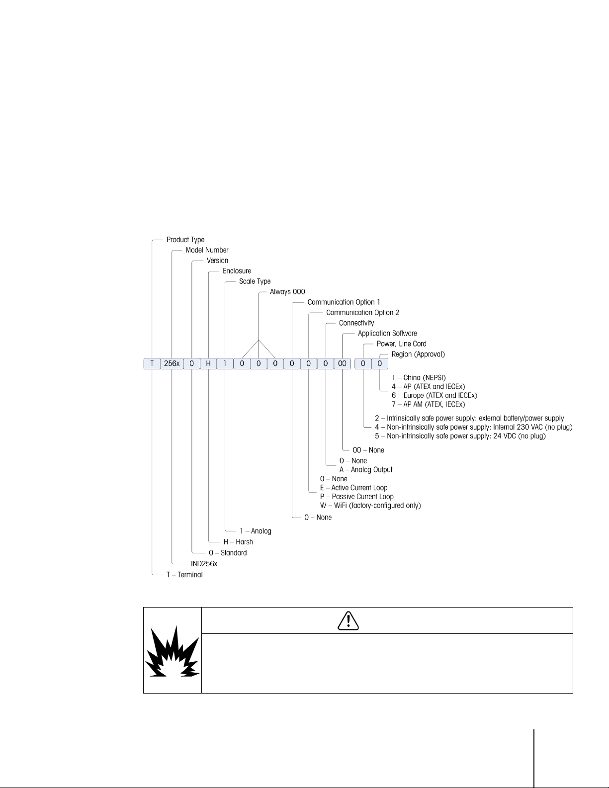
1.6. Configuration
1.6.1. System Configuration
Figure 1-1 shows the configuration options for the terminal.
Documentation CD (including manual and certificate of inspection)
Figure 1-1: IND256x Configuration Chart
WARNING
IND256x TERMINALS FACTORY-CONFIGURED WITH WIFI ARE APPROVED FOR USE IN ZONE 1
EQUIPMENT GROUP IIB CLASSIFIED AREAS. IND256x TERMINALS FACTORY-CONFIGURED WITH
WIFI MUST NOT BE USED IN EQUIPMENT GROUP IIC CLASSIFIED AREA. USING THE IND256X
TERMINAL FACTORY-CONFIGURED WITH WIFI IN A CLASSIFIED AREA FOR WHICH IT IS NOT
APPROVED COULD RESULT IN BODILY HARM AND/OR PROPERTY DAMAGE.
Page 17
1-8
METTLER TOLEDO IND256x Weighing Terminal User's Guide
30491440 | 02| 11/2019
Power input
AC power supply 220V (187-250V 50/60Hz) input (ATEX & IECEx version)
COM1 (standard)
intrinsically safe RS232
COM2 (optional)
intrinsically safe analog 4-20mA output or Wi-Fi communication module
NOTICE
WiFi CAPABILITY IS ONLY AVAILABLE IN IND256x TERMINALS SO CONFIGURED AT THE FACTORY.
1.6.2. Product Date Code
The manufacturing date or the date code for the terminal can be found on the serial data plate (on
the top of the enclosure).
The serial number will begin with a letter and a number (for example B212000371). The letter
represents the first three digits of the year per the date code chart in Table 1-3 (the letter “B” in our
Introduction
example represents “201x”) and the number is the unit’s digit of the year (the number “2” in our
example). So, “B4” decodes to the year 2014.
Table 1-3: Current and Later Date Code Formats
Date Code Year Date Code Year
A 200x F 205x
B 201x G 206x
C 202x H 207x
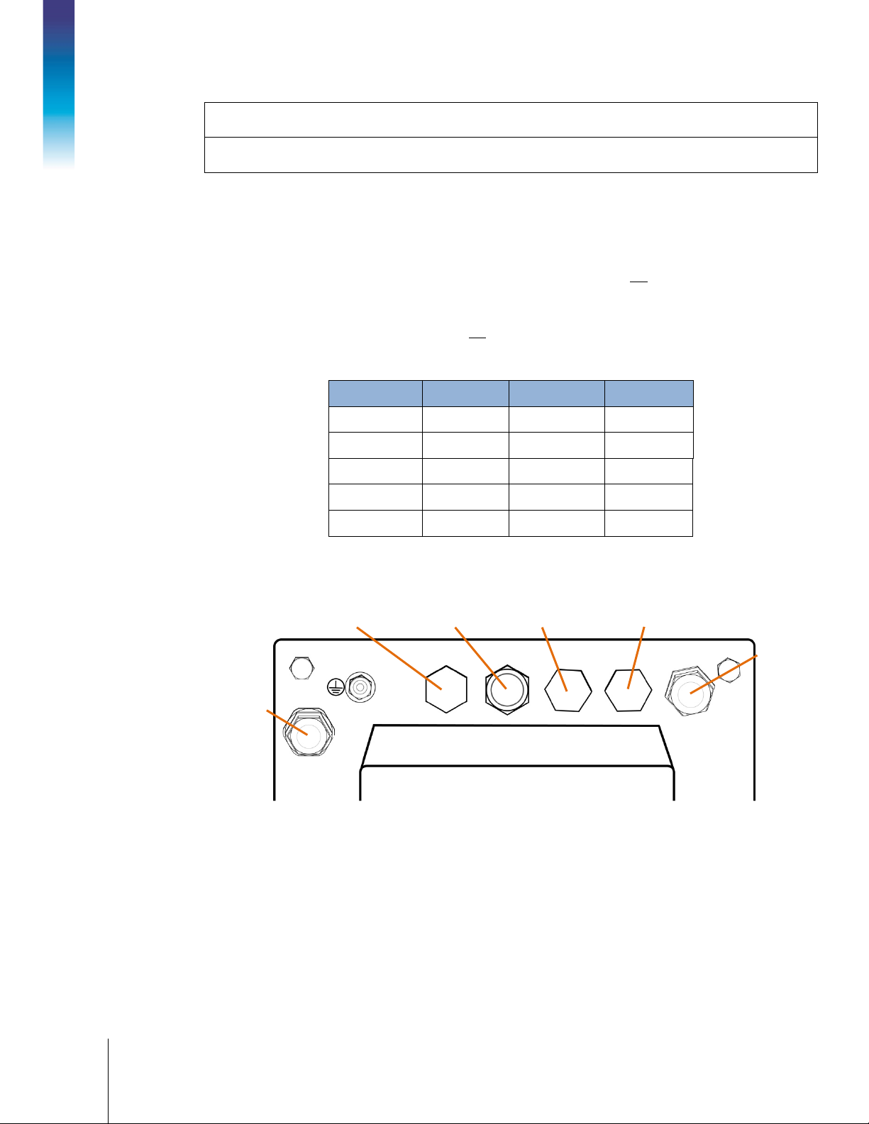
1.6.3. Connections
The following figure shows the connection locations on the back of the harsh enclosure.
COM3, optional COM2, optional COM, Reserved COM1, standard
Power input
D 203x J 208x
E 204x K 209x
Figure 1-2: IND256x Connection Port Locations
or
DC power supply 24V(18V-30V) input (ATEX & IECEx version)
or
external Ex battery
Weighing
platform
(factory-configured only)
Page 18

30491440 | 02 | 11/2019
METTLER TOLEDO IND256x Weighing Terminal User's Guide
1-9
COM3 (optional)
intrinsically safe active current loop
COM Reserved
Not used
1.6.4. Warnings
1.6.4.1. CENELEC
Connection of EB per Country-Specific Regulations: It must be ensured that the housings of all
devices are connected to the same potential via the EB terminals. No circulating current may flow
via the shielding of the intrinsically safe cables.
1.6.4.2. cFMus
Connection of EB per ANSI/NFPA 70, Article 504, and ANSI/IA RP 12.06.01 or Canadian Electric
Code C22.2: It must be ensured that the housings of all devices are connected to the same
potential via the EB terminals. No circulating current may flow via the shielding of the intrinsically
safe cables.
or
intrinsically safe passive current loop
1.7. Equipotential Bonding (EB)
Equipotential bonding must be installed by an electrician authorized by the owner. METTLER
TOLEDO Service performs only a monitoring and consulting function for this procedure.
Connect equipotential bonding of all devices (power supply unit, weighing terminal, interface
converter and weighing platform) in accordance with the terminal diagram and all country-specific
regulations and standards. In the process, it must ensure that:
• All device housings are connected to the same potential via the EB terminals.
• No circulating current flows via the cable shielding for intrinsically safe circuits.
• The neutral point for equipotential bonding is as close to the weighing system as possible.
1.8. Operating Environment
When selecting a location:
• Choose a stable, vibration-free surface to mount the terminal
• Ensure there are no excessive fluctuations in temperature and there is
sunlight
no direct exposure to
1.8.1.1. Temperature and Humidity
• Avoid drafts on the weighing platform (for example, from open windows or air conditioning)
• Calibrate the terminal after any major change of geographical location
The IND256x can be stored and operated at temperatures and relative humidity conditions as listed
in Table 1-1.
Page 19
1-10
METTLER TOLEDO IND256x Weighing Terminal User's Guide
30491440 | 02| 11/2019
1.8.1.2. Environmental Protection
The IND256x terminal has environmental protection as listed in Table 1-1.
1.9. Dimensions
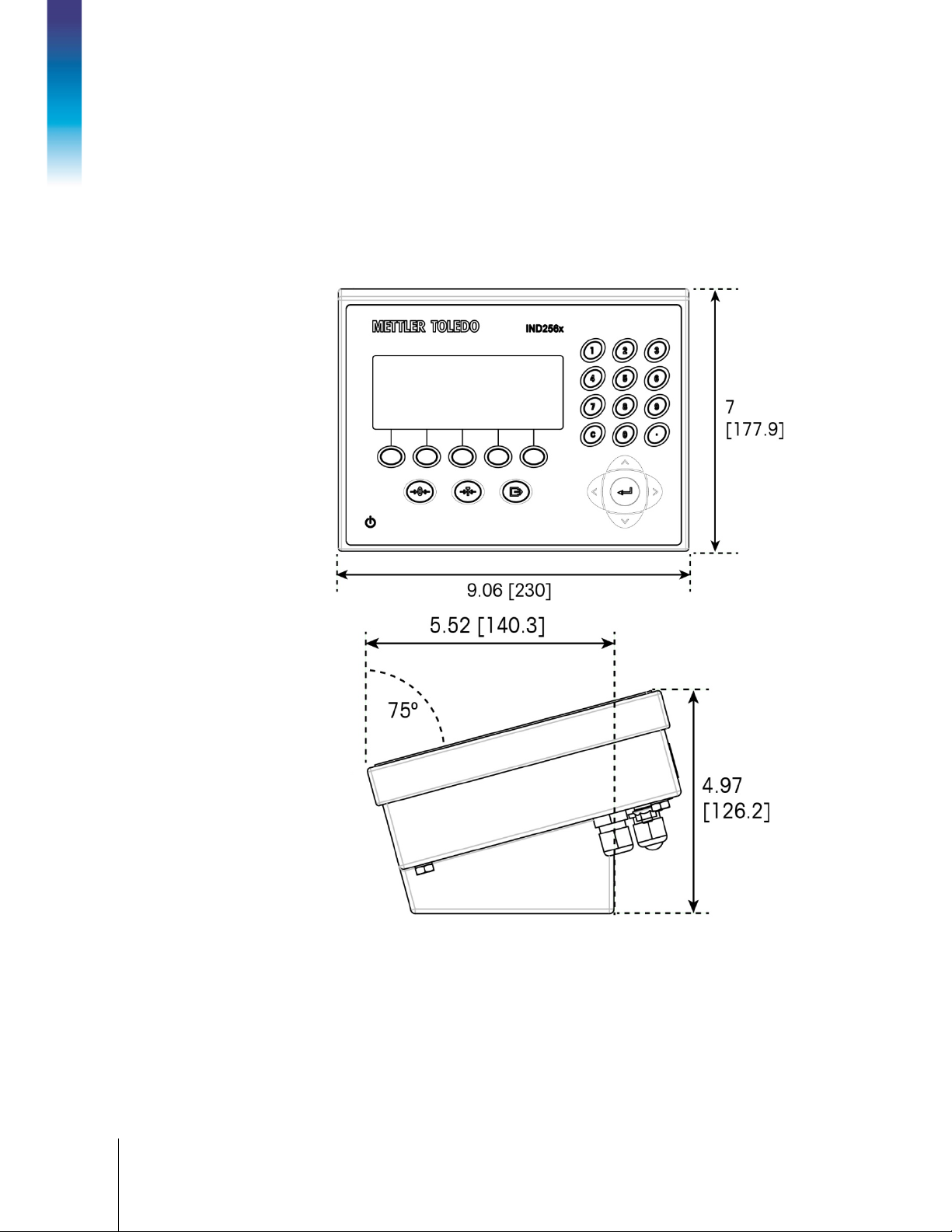
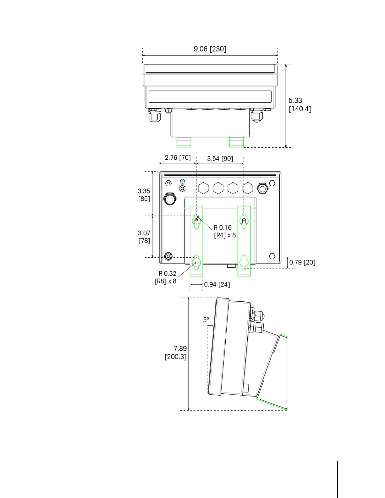
Figure 1-3 and Figure 1-4 show the terminal’s dimensions. Units are inches and [mm].
Introduction
Figure 1-3: IND256x Dimensions, Desktop Installation
Page 20
30491440 | 02 | 11/2019
METTLER TOLEDO IND256x Weighing Terminal User's Guide
1-11
Figure 1-4: IND256x Dimensions, with Fixed Wall-Mount Bracket
Page 21
1-12
METTLER TOLEDO IND256x Weighing Terminal User's Guide
30491440 | 02| 11/2019
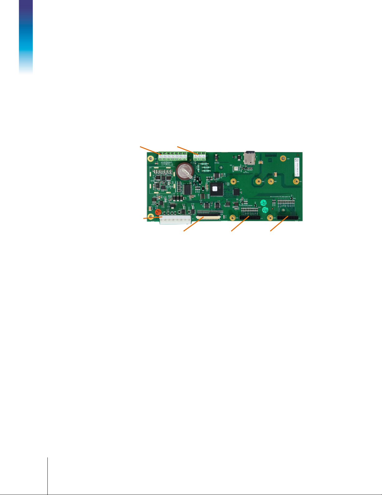
1.10. Main Board
The IND256x main board has the following main connections, indicated in Figure 1-5:
1. Analog load cell weighing interface
2. Intrinsically safe power input interface, connecting the power module
3. Flat ribbon harness interface, used to connect the display
4. Intrinsically safe RS232 interface (COM1)
5. Two communication option board interfaces (COM2 and COM3)
Introduction
1
4
2
3 5: COM2 5: COM3
Figure 1-5: IND256x Main Board
1.11. Communication Option Boards
The IND256x can be configured with a maximum of two of the three communication option boards
installed inside its enclosure. The options are:
• WiFi communication module (available only in IND256x terminals factory-configured with
WiFi)
• Intrinsically safe 3-20 mA analog output
• Active current loop for connection to communication module ACM200 located in the safe area,
or to connect second IND256x terminal configured with passive current loop option
• Passive current loop (used as the second display to connect another IND256x with active
current loop)
Page 22
30491440 | 02 | 11/2019
METTLER TOLEDO IND256x Weighing Terminal User's Guide
2-1
2 Operation
2.1. Overview
This chapter provides the navigation, basic features and functions of the IND256x terminal.
IND256x functions can be configured through the setup menu – refer to Chapter 3,
The specific operation of each IND256x terminal depends on the options installed, the functions
allowed in the setup menu, and the parameters configured.
2.1.1. User Security: Overview
Access to the terminal’s functions can be restricted according to the site’s security policies.
Restrictions may reflect legal and regulatory requirements, or site-specific standards.
The IND256x uses a password security mechanism to protect the setup menu. The password
function is off by default and can be enabled in setup.
Once set, the password must be kept safely. If the password is changed or forgotten, the setup
menu and some terminal functions will not be accessible. To recover access and functions, a
master reset must be performed, which will reset all user names and passwords and delete any
custom configuration.
Configuration.
2.1.2. Metrology Switch
The location of the metrology switch (S1-1) on the mainboard is indicated in Figure 2-1, and its
setting positions are shown in Figure 2-2. This switch is off by default; if it is
pressed), the terminal is sealed and users will not able to modify metrologically relevant setup
parameters.
on (the switch is
SW1-1 SW1-2
Figure 2-1: IND256x Metrology Switch Location
Page 23
2-2
METTLER TOLEDO IND256x Weighing Terminal User's Guide
30491440 | 02 | 11/2019
S1-1 Off
S1-1 On
Scale function keys
Numeric keypad
ENTER and navigation
Power button
System info line
Main display
Softkey icons
Softkey buttons
Tare display
Battery status indication
WiFi status indicator
Operation
2.2. Display and Keyboard
The IND256x has an LCD with white backlight, with a display screen resolution of 240 x 96 pixels.
Figure 2-3 shows the main elements of the terminal interface.
Figure 2-3: IND256x keyboard and display
Figure 2-2: Metrology Switch S1 Settings
keys
The system line displays system messages, battery and WiFi status indictors, and any
asynchronous error information; the middle area includes the application related weight, tare and
SmartTrac display, as well as entered values such as target ID and other information; and the
softkey icons are displayed at the bottom. To the right of the softkeys, an arrow indicates when
more rows of keys are available. These are accessed by using the navigation keys to scroll up ( )
or down ( ). Up to fifteen softkeys can be assigned in three rows. Softkey selection and position
are configured in setup.
Three scale function keys – zero, tare and print –appear below the softkeys. At right, 12 numeric
keys are used to enter data and commands. These keys include a clear key and a decimal point
key.
The ENTER key and four navigation keys are located below the numeric keys. These are used for
navigation and data entry during operation and in setup.
Page 24
30491440 | 02 | 11/2019
METTLER TOLEDO IND256x Weighing Terminal User's Guide
2-3
An ON/OFF key is located in the left lower part of the front panel.
2.2.1. Navigation Keys
The navigation keys (as shown in Figure 2-3) are used to browse the menu tree and set and apply
the window.
2.2.1.1. Up and Down Navigation Keys
These keys move the current cursor up and down to different settings in the menu tree (selected part
will be highlighted), move to different fields in the setting page to switch to another page of
available softkeys When the scroll bar indicates that there are two or three pages for configuration
fields related to specific parameters, up and down navigation keys are also used to move to next
page or previous page. The example in Figure 2-4 displays configuration parameter and it requires
two pages to display all relevant configuration fields. The scroll bar indication displays the specific
page in the two pages.
Scroll bar indicating
first page
Figure 2-4: Scroll Bar Example, Indicating Configuration Fields on Two Pages
Press the DOWN navigation key to move from Page 1 to Page 2. Press the UP navigation key to
move from Page 2 to Page 1.
2.2.1.2. Left and Right Navigation Keys
The left and right navigation keys are used to:
• Move into or out of levels in the menu tree
• Move within an editable field during data entry
• Allow left- and right-scrolling to the left and right, to view all available information in the
window
2.2.1.3. Enter Key
The ENTER key is used to:
• Open a setup page to view parameters, and enter the parameter’s configuration field in
order to modify or select its value
Scroll bar indicating
second page
Page 25
2-4
METTLER TOLEDO IND256x Weighing Terminal User's Guide
30491440 | 02 | 11/2019
• Confirm the set value in the menu
• Accept the new value entered in the field and move the focus to next field label
2.2.2. Softkeys and Icons
There are five softkey buttons (indicated in Figure 2-3) along the bottom of the display window.
These correspond to the softkey icons displayed on-screen immediately above each key. Five
softkey icons can be displayed simultaneously, with a maximum of 15 overall, divided into three
separate rows. The down and up symbols to the right of the icons indicate the availability of more
rows; use the UP and DOWN navigation keys to display additional rows.
Operation
Softkey configuration and customization is detailed in Chapter 4,
Configuration.
The softkey and application displays are identified by icons. Table 2-1 lists these icons and their
functions and classifies them according to their use in HMI.
Table 2-1: Softkey Icons and Functions
Icon Function Icon Function
Scale Calibration Icons
CalFree
Span calibration
Start calibration test
Tare Memory (access the tare table)
Table, Memory and Function access
Zero calibration
Step calibration
Target Value View (access the
target value table)
Alibi Memory
Report (set printing of Alibi memory,
transaction log, tare and target table)
Tare Value view
Totals Report
Enter setup menu
Print
Transaction log
Target Value
ID (customized information, ID1,
ID2 and ID3 available)
Transaction Counter
Date/Time setting
Repeat Print
Page 26
30491440 | 02 | 11/2019
METTLER TOLEDO IND256x Weighing Terminal User's Guide
2-5
Icon Function Icon Function
ZERO
TARE
PRINT
Printing
View System Information
Edit
Clear All
Delete
Edit
Cancel (exit without saving)
Expand displayed resolution by 10
Minimum Weight function
2.2.3. Scale Function Keys
The scale function keys in Figure 3-2 are:
When the weighing platform is empty, the terminal displays 0 kg. Gross weight zero
reference is recorded during calibration. If pushbutton zero is allowed in the
configuration and the weight is within the zero range, the zero function key may be
pressed to capture a new gross weight zero reference point.
Display Icons
Exit (return to previous window)
New
Confirm input or transaction
Contrast Control
Unit switch – change units
Tare refers to the weight of an empty container. It is generally used to determine the
net weight of the container’s contents. Press the tare function key when an empty
container is placed on the weighing platform to display a net weight of zero. When
material is added to the container, the terminal displays their net weight.
When the empty weight of the container is known, the tare may be entered using the
numeric keypad and pressing the tare function key to store the value. The terminal will
display the net weight of the materials in the container. The keyboard tare must be
allowed, so that this method can be used for key tare operation. If the auxiliary tare
display is allowed, the tare value and tare type will be displayed in the bottom left of
the screen.
Pushbutton tare must be enabled in setup in order to use either of these methods
for tare operation.
Press the print function key to initiate a demand output of data in the print template
configured in setup. A serial or WiFi print connection must be configured to connect
the template to the selected serial or WiFi port. When a print command is issued, they
system line displays
for 3 seconds.
Page 27
2-6
METTLER TOLEDO IND256x Weighing Terminal User's Guide
30491440 | 02 | 11/2019
CLEAR
In net weight mode, press the clear function key to clear the current tare value. The
Operation
2.2.4. Numeric Keypad
display will return to gross mode. Clear can be operated regardless of whether there is
motion on the platform. Please note that once the tare value has been cleared, it can
no longer be read back. It is necessary to re-execute the tare process described
above.
During numeric input using the keypad, the clear function is similar to a backspace
key. Use the right arrow key to place the cursor at the end of the data to be deleted
and press the clear key. A character is deleted by each press of the clear key. When
the data input box is entered for the first time, the previous input will be selected; in
this case, press clear to delete the existing value.
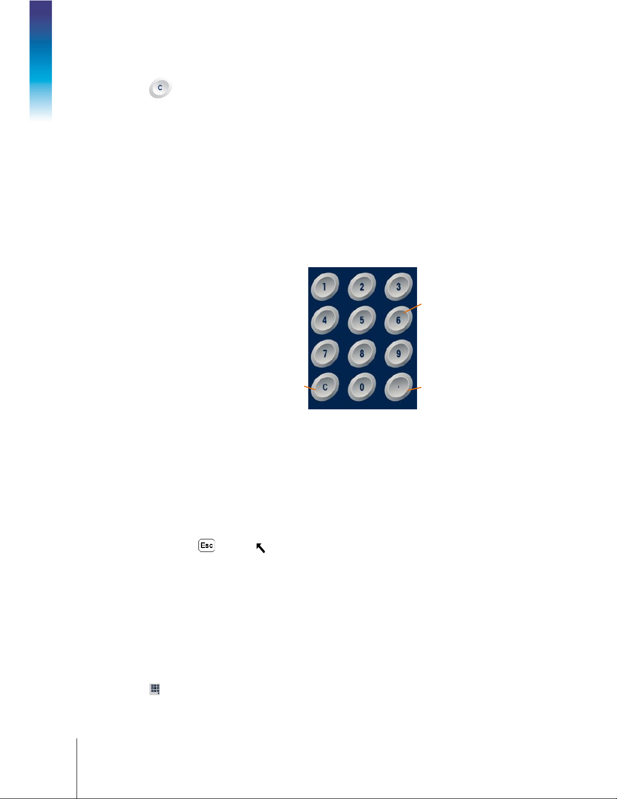
When data input is required, use the 12-key numeric keyboard (shown in Figure 2-5) to enter the
numbers.
Numeric key
Locate the cursor in the field as described in section 2.2.1, above) and press the numeric key to
enter the appropriate data. When necessary, press the decimal point key to enter a decimal point.
During data input, the clear key function functions like a backspace key. Locate the cursor at the
end of the data to be deleted and press C. One character is deleted by each press of the clear key.
When a data input field is selected for the first time, the whole data string is selected state. Press
clear to delete the existing input.
The Escape and Exit keys exit the data input process and abandon any newly-entered data.
Data that was in the field before the entry process began will be retained.
Once the required letter, number and character are entered in the proper field of the window, press
Enter to accept the input.
2.3. Data Input
The standard keypad only supports the entry of numeric characters; however, alphabetic entry is
supported for specific functions, such as the ID table shown in Figure 2-6. When the keypad softkey
( ) is displayed, pressing it opens the alpha character entry screen. INS-ABC will appear at upper
right, to indicate the entry mode.
Clear key
Figure 2-5: Numeric keyboard layout
Decimal point and
symbols key
Page 28
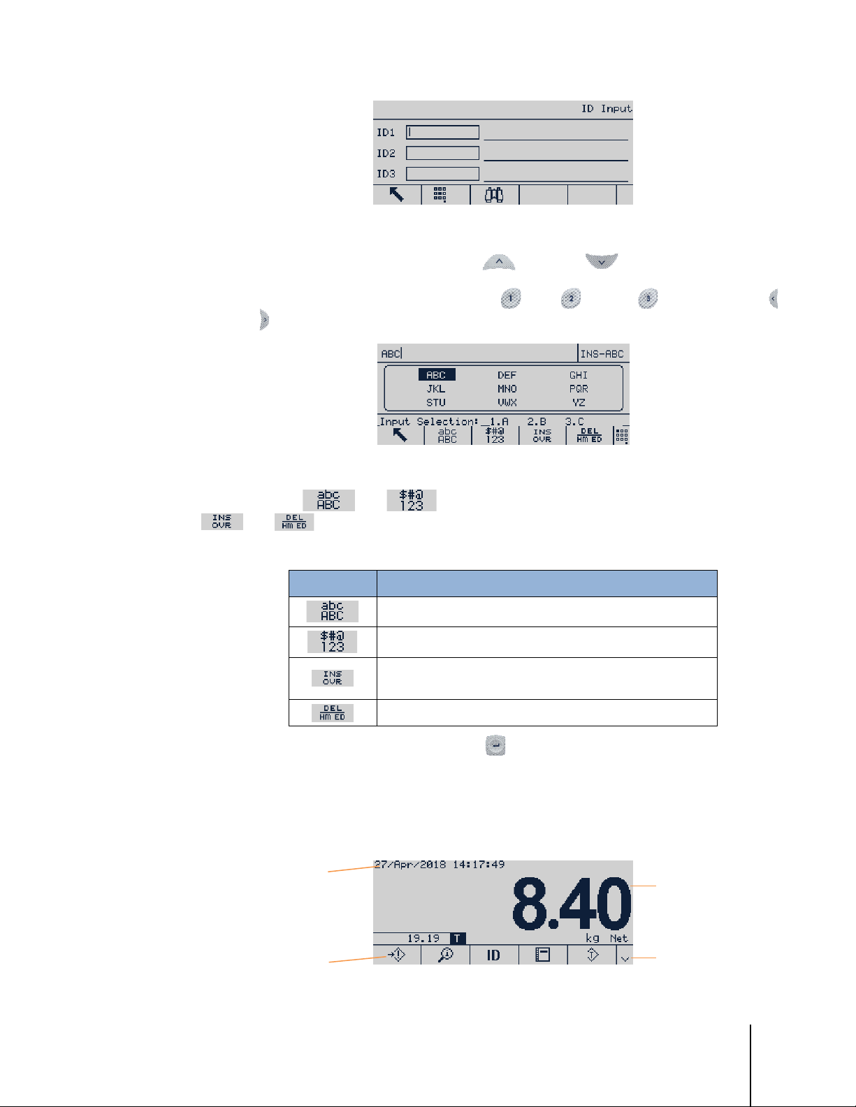
30491440 | 02 | 11/2019
METTLER TOLEDO IND256x Weighing Terminal User's Guide
2-7
Figure 2-6: ID Input Display
System line
Softkey icons
Weight and
application area
More down symbol
indicate more soft
choices
Once in alphanumeric entry mode, use the up
and down
keys to select different
character blocks. Once the correct block is selected, use the numeric keys to select the character for
input. In the example shown in Figure 2-7, press for A, for B, or for C. Use the left
and right navigation keys to move the position of the selection in the array of character options.
Figure 2-7: Alphanumeric Input Screen
Use the softkeys
and
Softkey Function
and
to select alternative input modes. A further two softkeys
, select and delete the character next to the cursor, respectively.
Table 2-2: Softkey Function
Lower or upper case letters
Symbols or numbers
Select the character next to the cursor; the next character
entry will overwrite the selected character.
2.4. Main Display
Delete the character next to the cursor
When the data entry is complete, press ENTER to confirm.
Figure 2-8 shows the main display.
Figure 2-8: Main Display
key
Page 29
2-8
METTLER TOLEDO IND256x Weighing Terminal User's Guide
30491440 | 02 | 11/2019
No WiFi Connection
WiFi Connected
The appearance of the display will vary according to the terminal configuration, but it can contain:
System Line
Weight and
Application Area
Softkey Icons
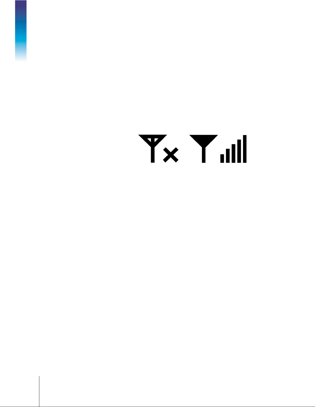
2.4.1. WiFi Status Indication
Operation
The WiFi status indicator shows when a WiFi connection exists, and displays bars to indicate
signal strength.
Displays system information and status, such as date/time, error message,
indication of WiFi connection
Displays the weight, unit, tare and specific weighing data of other applications
Displays the icons of currently available softkey functions. If the More Down and
More Up symbol is displayed at right, further softkeys are available in additional
rows.
Figure 2-9: WiFi Status Indicator
Page 30
30491440 | 02 | 11/2019
METTLER TOLEDO IND256x Weighing Terminal User's Guide
3-1
3 Configuration
This chapter provides information about configuring the IND256x from the setup menus.
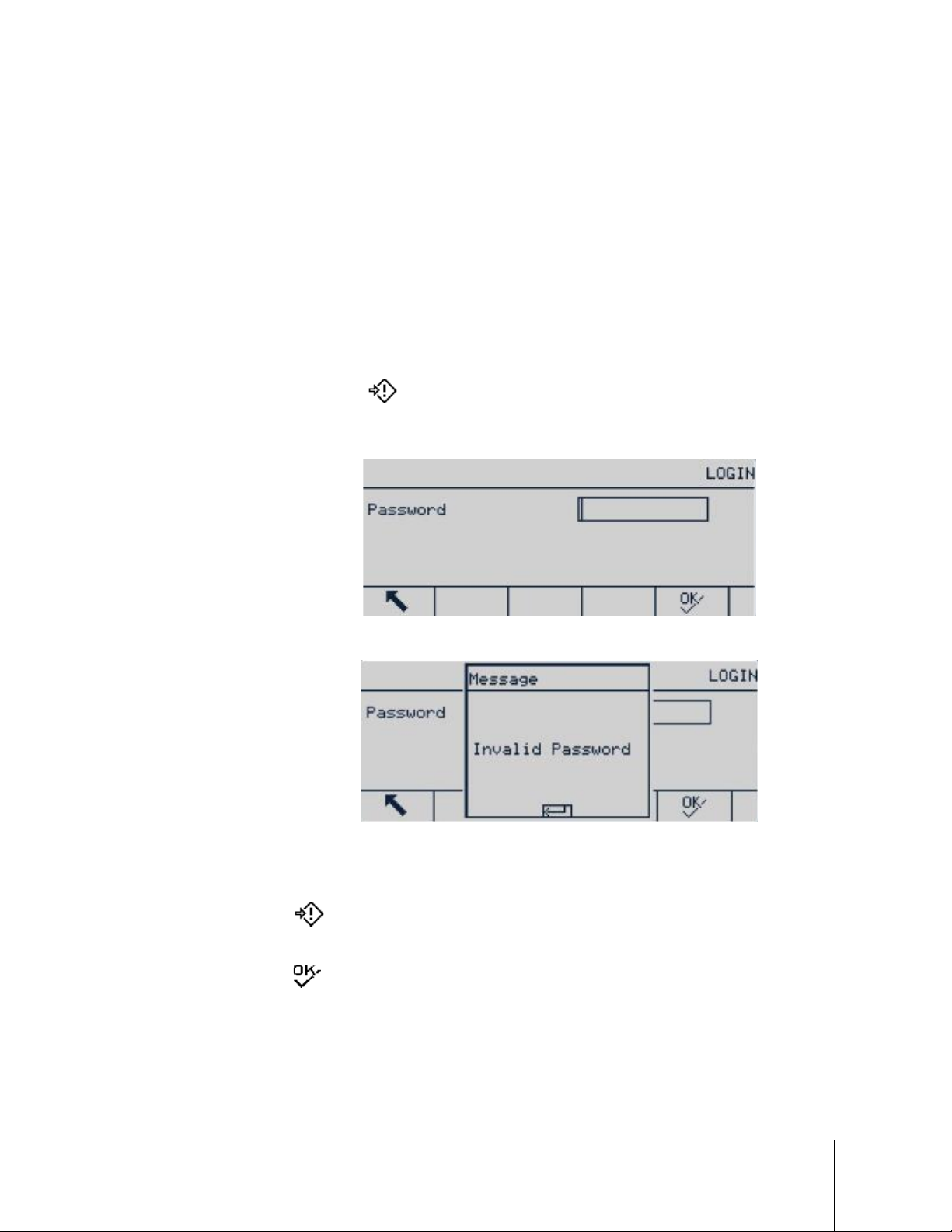
3.1. Enter Setup
Click the SETUP icon
set, a login screen appears. In this case, the setup menu may be entered only by entering a correct
user name and password.
to enter the terminal’s setup menu. If the user name and password are
Figure 3-1: Login Screen
Figure 3-2: Password Error Message
3.1.1. Enter Password
1. Press
2. Enter the numeric password.
3. Press
incorrect, an error prompt will be displayed. Press ENTER to directly exit to the weighing
interface.
to display the password input box.
key. If the password is correct, the setup menu tree will appear; if the password is
Page 31

3-2
METTLER TOLEDO IND256x Weighing Terminal User's Guide
30491440 | 02 | 11/2019
Parameter label,
highlighted
Parameter value
3.2. Exit Setup
Press Exit
3.3. Setup Menu
The setup menu of IND256x is shown in Figure 3-3.
Configuration
Use the UP, DOWN, LEFT and RIGHT navigation keys to select item. The selected menu item
appears in a reverse highlight. When the desired item is selected, press OK to enter the submenu.
3.3.1. Setup Screens
The setup screens are used to view, enter or modify setup parameters.
to exit to the main menu.
Figure 3-3: Setup Menu
3.3.1.1. Selecting Parameters
Use the UP and DOWN navigation keys to move between different parameter labels. If the setup
screen of a parameter exceeds one page, a vertical scroll bar will appear in the right to indicate
this. The dark area of the scroll bar indicates which part of the screen is currently displayed.
3.3.1.2. Entering Data
Press Enter to move focus from the field label to the selection box or textbox; enter or edit data here.
Figure 3-4: Setup Screen Example (Time and Date Setting)
Page 32

30491440 | 02 | 11/2019
METTLER TOLEDO IND256x Weighing Terminal User's Guide
3-3
Scale
Application
Terminal
Communication
Maintenance
Selection
box in focus
Figure 3-5: Setup Screen
If the parameter values are provided in a drop-down selection box, press ENTER to select the
current value. Choose other values from the selection box using the UP and DOWN navigation keys.
Once the desired value is selected, press OK to confirm. Focus will move to the next parameter
label.
If a parameter value is a textbox and allows alphanumeric entry, press the keypad softkey to
use the keypad.
Figure 3-6: Select Parameter
Refer to section 2.3, Data Input, in chapter 2, Operation, for further details.
3.4. Configuration Overview
All configuration screens may be accessed from the setup menu tree. In each branch’s main
screen, use the navigation keys to select the required setup screen, and then press Enter to display
that menu.
There are five main submenu branches in the setup menu:
This chapter explains the available parameters, their settings, and the use of each menu.
Page 33

3-4
METTLER TOLEDO IND256x Weighing Terminal User's Guide
30491440 | 02 | 11/2019
3.5. Scale
If the metrology switch SW1-1 is ON, the user will not be able to access the Scale parameter
menus. Refer to section 2.1.2.,
The scale menu is used to configure the following parameters:
Metrology Switch, in chapter 2, Operation.
Configuration
A Reset operation located at the bottom of the list may be executed to reset some parameters in the
Scale menu to default values. This action does not clear metrological data.
3.5.1. Scale Type
The Scale Type menu is used to set the scale name, type, approval method and approval number.
Press the
3.5.1.1. Name
The Name field allows a name to be assigned to the scale. Enter identifying information of no more
than 20 characters and press
Figure 3-7: Scale Menu, Two Pages
Exit softkey to return the display to the Scale menu.
Figure 3-8: Scale Type Menu
Enter to store the name and move to the next parameter label.
3.5.1.2. Scale Type
Type field indicates the type of scale supported by the terminal and allows selecting remote display
mode. If
3.5.1.3. Approval
Approval refers to the approval configuration of the terminal and platform.
Various
Approval selection list contains:
Remote is selected, the approval option will be disabled. Options are:
Analog [used for analog version by default], Remote
Approval methods may be legally used for corresponding countries and regions. The
Page 34

30491440 | 02 | 11/2019
METTLER TOLEDO IND256x Weighing Terminal User's Guide
3-5
None [default]
Thailand
Canada
Australia
OIML
USA
If any approval method is selected, the parameters related to metrology in the
locked and cannot be modified. Select OIML approval for China.
3.5.1.4. Certification No.
Enter an approval number of up to 20 digits.
3.5.2. Capacity & Increment
Use this menu to set the primary weighing unit, range and division value and overload display
range.
3.5.2.1. Primary Unit
Set the Primary units from the options in the selection box, including:
Scale menu will be
Figure 3-9: Capacity & Increment Screens
g, kg [default], lb, t, ton
3.5.2.2. Range/Intervals
Select multi-interval or multi-range mode and then set the number of ranges or intervals from the
selections:
1 [default], 2intervals, 2 ranges, 3 intervals, 3 ranges
3.5.2.2.1. >|1|< – range/interval value 1
Specify the capacity and then the increment size for range or interval
3.5.2.2.2. >|2|< – range/intervalvalue 2
When two ranges or intervals are selected, the second range or interval value should be entered.
The range 2 must be greater than the input value of range 1.
3.5.2.2.3. >|3|< – range/intervalvalue 3
When three ranges or intervals are selected, the third range or interval value should be entered.
Page 35

3-6
METTLER TOLEDO IND256x Weighing Terminal User's Guide
30491440 | 02 | 11/2019
Disabled [default]
Only use zero and span
3 points
Use zero, midpoint and high point
4 points
Use zero, low point, midpoint and high point
5 points
Use zero, low point, midpoint, mid-high point and high point
3.5.2.3. Blank Over Capacity
Select the appropriate number of divisions to determine how many displayed divisions above
capacity the terminal can display before the display is blanked. In this overcapacity situation, a
dotted line will be displayed instead of a weight value, and the immediate data output is disabled.
3.5.3. Calibration
The GEO code adjustment value (gravitational acceleration factor), base (scale) serial number,
calibration unit and linearity adjustment are set in the calibration screen. When the Scale Type is set
Remote, the calibration branch is not available.
as
Configuration
Figure 3-10: Calibration Screens
3.5.3.1. GEO Code
In the GEO Code field, enter the appropriate geographical adjustment value for current geographic
position. The geo code is numbered from 0 to 31. Refer to Appendix C,
the correct GEO code for the installation site.
The GEO value is used to translate factory calibration values to local settings, making it
unnecessary to do an on-site calibration. It cannot be adjusted for a weighing system which has
been calibrated at the customer’s site.
3.5.3.2. Base Serial Number
If appropriate, enter the serial number of the connected scale. Entries of up to 13 characters are
accepted.
3.5.3.3. Calibration Units
The available calibration units are the same as the primary units, and include:
kg [default], lb, t
g,
3.5.3.4. Linearity Adjustment
Select linearity adjustment from the selection box. The options are:
Geo Codes, to determine
Page 36

30491440 | 02 | 11/2019
METTLER TOLEDO IND256x Weighing Terminal User's Guide
3-7
3.5.3.5. Calibration SoftKeys
The softkeys displayed in the calibration setup screen are used for several calibration processes.
3.5.3.5.1. Capture Zero
The Capture zero softkey triggers an independent operation to reset the scale zero condition.
Capture Zero Steps
1. Press capture zero softkey .
2. A message appears instructing the user to clear the platform.
3. Clear the platform and press start softkey to display capture zero operation status.
Capture zero
Capture range
Figure 3-11: Zero Calibration
Step calibration
Calibration-free
Press Escape softkey to cancel the zero calibration process and return the display to
previous screen.
4. When the operation is complete, a final status message appears, indicating that zero capture is
complete.
If there is scale motion during the zero capture process, the terminal will accept the unstable
weight reading and then display a warning message to indicate the use of an in-motion value.
This message offers
Yes and No options, and the user may reject or accept the calibration.
Move the cursor to the desired action and then press ENTER.
Figure 3-12: Zero Calibration (Unstable)
5. When zero capture is successful, a message will appear, showing "Capture zero ok". If the zero
capture is not successful, an error message appears, showing "Capture zero failure ". In this
case, repeat the zero capture process. If the process continues to fail, contact your METTLER
TOLEDO representative for assistance.
Page 37

3-8
METTLER TOLEDO IND256x Weighing Terminal User's Guide
30491440 | 02 | 11/2019
Figure 3-13: Zero Calibration (Failed)
6. Press the Esc softkey to return to the calibration screen.
3.5.3.5.2. Capture Span
Configuration
The Capture Span softkey
starts the process, which can be performed independent of
capturing zero. To capture span, enter the test load in the appropriate field. The method used
depends on whether
If Linearity is Disabled
Linearity is disabled or enabled.
1. Press CAPTURE SPAN
. The capture span setup screen will appear. Enter the full-scale
calibration weight, then press ENTER.
Figure 3-14: Test Load Entry Screen
2. Press START softkey to start the weight capture operation status. A display will indicate
progress. When the operation is finished, a status message appear indicating that span has
been captured successfully.
If required, press ESC softkey
to cancel the calibration process and return the display to
previous screen.
3. If capture span is successful, an approval message appears, showing "Capture span ok ". If
the capture span is not successful, an error message appears, showing "Capture span failure".
Repeat the capture span steps in case of calibration failure. If the process continues to fail,
contact your METTLER TOLEDO representative for assistance.
Figure 3-15: Span Calibration in Progress
Page 38

30491440 | 02 | 11/2019
METTLER TOLEDO IND256x Weighing Terminal User's Guide
3-9
Figure 3-16: Span Calibration, Success and Failure
If there is scale motion during the span capture process, the terminal will accept the unstable
weight reading and then display a warning message to indicate the use of an in-motion value.
This message offers
Yes and No options, and the user may reject or accept the calibration.
Move the cursor to the desired action and then press Enter.
4. Press the ESC softkey to return to the calibration screen.
Figure 3-17: Span Calibration (Unstable)
If Linearity is Enabled
In this case, the screen will display two calibration weight input boxes. Enter load weights #1 and
#2 and press ENTER to confirm. Then enter the span calibration interface and press Start. The
message "Capture span ok" shows that the calibration is successful.
Page 39

3-10
METTLER TOLEDO IND256x Weighing Terminal User's Guide
30491440 | 02 | 11/2019
Configuration
Figure 3-18: Span Calibration (Success)
"Calibration Failure” will be displayed if the terminal does not succeed in capturing the span.
Figure 3-19: Span Calibration (Failed)
If there is scale motion during the span capture process, the terminal will accept the unstable
weight reading and then display a warning message to indicate the use of an in-motion value.
This message offers
Move the cursor to the desired action and then press Enter.
Yes and No options, and the user may reject or accept the calibration.
Page 40

30491440 | 02 | 11/2019
METTLER TOLEDO IND256x Weighing Terminal User's Guide
3-11
3.5.3.5.3. Step Calibration
In step calibration, the same amount of test weight is added at each step of the calibration
procedure.
To Execute Step Calibration
1. Press the step calibration softkey . The step calibration setup screen appears.
Figure 3-20: Range Calibration (Motion)
Figure 3-21: Accessing Step Calibration
2. Press ENTER to access the target weight field, and enter the weight of the test load. (The same
amount of test load weight will be used in each step). Press OK to confirm.
Figure 3-22: Entering Test Weight Value
3. Press the Start softkey . The step calibration screen appears. This screen displays the target
weight entered in previous screen, together with the prompt "Add test weight". Place the test
weight and press OK
4. Place the correct test weight on the scale and press OK
.
.
Page 41

3-12
METTLER TOLEDO IND256x Weighing Terminal User's Guide
30491440 | 02 | 11/2019
Configuration
5. Repeat steps 3 and 4 until sufficient calibration steps have been completed. Once the process
is complete, a screen will show the final target value, then show a "Calibration Successful"
message.
6. Press Enter to return to the calibration screen.
At any step in the procedure, press EXIT to stop the process and return to the calibration screen.
3.5.3.5.4. CalFree (Weight-Free Calibration)
The CalFree softkey provides access to the span calculation screen and can achieve
platform calibration without test weights. Before CalFree operation, make sure that the correct value
has been entered for the analog gain jumper. If the value is not set correctly, it will cause error in
CalFree calculation.
Figure 3-23: Step Calibration in Progress
Figure 3-24: Step Calibration Sequence
Range Calibration Using CalFree
1. Press CALFREE softkey and CalFree screen appears.
2. Enter the load cell capacity, press ENTER and select appropriate unit.
The sum of the capacities of all the load cells should be entered here. For example, for a
storage tank with three 5000kg sensors, the sensor capacity will be 3 x 5000 kg, i.e.
15000 kg.
3. Enter the rated load cell sensitivity output value and then press ENTER.
Page 42

30491440 | 02 | 11/2019
METTLER TOLEDO IND256x Weighing Terminal User's Guide
3-13
If several load cells are used, the average value of the sensitivity of all cells should be
entered here. The average output is determined by adding the output of all cells and then
dividing by the number of cells.
4. Enter the estimated preload value in relevant field. The estimated preload is any input. During
the calibration, the terminal tests whether there is analog/digital (A/D) converter input saturation
in full platform range. If a value is entered in this field, the estimated preload is accounted for in
the calculation. If the preload is unknown, leave this field blank.
This preload value is only used to determine the overload conditions and not used as zero
reference point. The zero reference point must be captured by the normal zero calibration
procedure.
Figure 3-25: Configuring CalFree
5. Press OK
6. If calibration succeeds, a message will appear, showing "Calibration ok". If calibration fails,
7. Press the EXIT softkey to return to the calibration screen.
3.5.4. Zero
Zero function is used to set or reset the initial zero reference point of the IND256x. There are three
zero setting modes:
in the pull-down menu.
Figure 3-26: CalFree Calibration Process
repeat the CalFree procedure. If the process continues to fail, contact your local METTLER
TOLEDO representative for help.
• Auto zero
• Power up zero
• Pushbutton zero
This section describes the auto zero, auto zero range, under zero blanking, power up zero and
pushbutton zero settings.
Page 43

3-14
METTLER TOLEDO IND256x Weighing Terminal User's Guide
30491440 | 02 | 11/2019
Figure 3-27: Zero Screens
Press the Zero key within the allowed zero range and the weighing display controller will clear
the current weight value to zero.
If the platform is motion, the motion indicator will appear, and the terminal will not be able to
Configuration
3.5.4.1. Auto Zero
complete the zero operation.
Use the Auto Zero parameter to select auto zero maintenance parameters. The options are:
Disabled,
3.5.4.2. Auto Zero Range
Auto zero maintenance (AZM) allows IND256x to compensate for a small amount of weight
deviation (such as from debris on the scale), and return it to the center of zero. When the terminal
is within the AZM operation range and is not in motion, the terminal makes small adjustment to
current zero reading to gradually approach the true zero center weight. When the weight is beyond
the programmed AZM range, this function will not work.
The auto zero tracking range is in the unit of division(d) value. The options are
0.5d [default], 1d, 3d, 10d
3.5.4.3. Under Zero blanking
The underload range determines how far below calibrated zero the scale weight can fall before the
display blanks (displays a dotted line). This range is defined in divisions. The options are:
Disabled [default], 10d, 20d
3.5.4.4. Power Up Zero
If Power-Up Zero is enabled, the terminal attempts to capture zero at power up, provided the scale
is within the range specified here. If Power up zero is disabled, the initial reference at power up will
be recovered to the most recent zero reference. Power Up Zero Range
Gross [default], Gross and Net
When Power up zero is enabled, – Range and + Range fields will display. These are used to set the
range above and below the original calibration zero point of the platform within which the terminal
can use power up zero. The range unit is defined as a percentage of calibrated span. The options
are:
Disabled [default], +/-2%, +/-10%
Page 44

30491440 | 02 | 11/2019
METTLER TOLEDO IND256x Weighing Terminal User's Guide
3-15
For example, if the power up zero and range setting is set at 2%, the power up zero will occur only
when the weight reading in the scale is less than 2% of the scale range above the original scale
calibrated zero reference.
If power up zero capture is enabled and the weight in the scale is beyond the zero capture range,
the display will indicate EEE until the weight is adjusted to within the range.
3.5.4.5. Pushbutton Zero
If Pushbutton Zero is enabled, the ZERO key in the keyboard can be used to capture a new zero
reference point. Pushbutton zero options are:
Disabled,
If Pushbutton Zero is disabled, a remote zero command may still be executed through SICS,
+/-2% [default], +/-20%
CPTZ and SMA commands from PC, discrete input or PLC. To set the zero point range of such
remote zero functions, enable pushbutton zero first, select the pushbutton zero range and then
disable pushbutton zero.
3.5.4.5.1. Pushbutton Zero Range
If Pushbutton zero is enabled, – Range and + Range fields will display. These are used to set the
range above and below the original calibration zero point of the platform where Pushbutton zero
can be used. The range unit is a percentage of calibrated span.
For example, if the pushbutton zero and range setting is set at 2%, the pushbutton zero will occur
only when the weight reading in the scale is less than 2% of the scale range above the original
scale calibration zero reference. If the pushbutton zero and range setting is set at 2%, the
pushbutton zero will occur only when the weight reading in the scale is less than 2% of the scale
range below the original scale calibration zero reference.
3.5.4.5.2. Using Pushbutton Zero
The Pushbutton (semi-automatic) zero function can be carried out in two ways:
• Press the ZERO scale function key
• Serial command (SICS or CTPZ protocol)
3.5.5. Tare
Tare refers to the weight of an empty container. Tare is used to subtract the weight of the container
from the scale gross weight to determine the net weight of the containers contents. If the platform is
in motion, Tare is disabled. This branch provides parameters for tare type, auto tare and auto clear.
Figure 3-28: Tare Menu
Page 45

3-16
METTLER TOLEDO IND256x Weighing Terminal User's Guide
30491440 | 02 | 11/2019
1. Press the Tare key to use current weight as tare. The display will switch from gross weight
mode to net mode, and show a net weight of zero. The net weight indicator will display.
2. If the scale is in motion, the terminal will be unable to perform the tare function.
3. Press the CLEAR key to clear current tare value. The display will return to the gross weight
mode. The net weight cursor will be converted to gross weight cursor.
3.5.5.1. Tare Type
Use the Tare Types setup screen to enable or disable pushbutton tare, keyboard tare and net sign
correction.
Configuration
Figure 3-29: Tare Type Screen
3.5.5.1.1. Pushbutton Tare
If pushbutton tare is enabled, tare can be captured by placing an empty container on the scale and
pressing the Tare key
indicator. When the container is filled and placed back on the scale, the net weight of the material
will display. The options are:
Disabled,
If Pushbutton Tare is disabled, remote tare can still be executed through SICS, CPTZ and SMA
Enabled [default]
commands and discrete input from PC or through PLC command.
3.5.5.1.2. Keyboard Tare
When the keyboard tare is enabled, use the numeric keypad to enter the given value (preset tare) of
the empty container weight (tare), then press ENTER . The terminal will display the net weight of
the content in the container. Keyboard tare is automatically rounded to the nearest display division.
Options are:
Disabled,
3.5.5.1.3. Net Sign Correction
Net sign correction is used for factory receiving and shipping applications. If net sign correction is
enabled, the terminal will switch the gross weight and net weight fields in the printed bill when
necessary, so that the larger weight is always the gross weight and the smaller weight always the
tare, and their difference is always positive net weight. Net sign correction affects the print data
output and the terminal’s displayed weight. Continuous data output will continue to display negative
net weights. Options are:
. The terminal will display a zero net weight and the net weight mode
Enabled [default]
Disabled [default], Enabled
Page 46

30491440 | 02 | 11/2019
METTLER TOLEDO IND256x Weighing Terminal User's Guide
3-17
Net sign correction will use pushbutton tare, preset tare or the tare record operation stored in the
Tare Table. Table 3-11 displays the example of the weight value with and without net sign
correction. In this example, the tare memory value is 53 kg and the existing weight on the scale is
16 kg.
Table 3-1: Weight Value With and Without Net Sign Correction
When net sign correction is enabled, the tare field read from the display will be marked the
letter "M" to indicate "memory" rather than "T" or "PT".
3.5.5.2. Auto Tare
Use the Auto Tare screen to enable or disable auto tare, set tare and reset threshold weights, and
enable or disable motion check. Auto tare options are:
Printed and displayed Disabled Enabled
Gross weight 16 kg 53 kg
Tare 53 kg 16 kg
Net weight
Disabled [default], Enabled
Net Sign correction
− 37 kg
37 kg
3.5.5.2.1. Auto Tare
3.5.5.2.2. Tare Threshold Weight
Figure 3-30: Auto Tare Screens
When auto tare is enabled and a container heavier than the threshold weight is placed on the scale,
the tare operation is performed automatically once the scale is stable. Options are:
Disabled [default], Enabled
When the weight on the scale exceeds the set tare threshold and is stable, the terminal tares
automatically.
Page 47

3-18
METTLER TOLEDO IND256x Weighing Terminal User's Guide
30491440 | 02 | 11/2019
3.5.5.2.3. Reset Threshold Weight
Reset threshold weight must be less than the tare threshold weight. When the weight on the scale
falls to below the reset threshold, e.g. when the load has been taken away, the terminal compares
the current weight on the scale with the reset threshold weight. If current weight is below the
threshold value, the terminal is ready to execute the next auto tare operation, as described in
section 3.5.5.2.2.
3.5.5.2.4. Motion Check
When Motion Check is enabled, the terminal will check whether the weight on the scale is stable, so
as to judge whether to execute auto tare operation. Options are:
Configuration
3.5.5.3. Auto Clear
Disabled
Use the Auto Clear screen to set auto clear, set the clear threshold weight, enable or disable motion
check for auto clear, clear after print, clear when the scale is zeroed, and the power up setting. The
options are:
Disabled [default], Enabled
, Enabled [default]
Figure 3-31: Auto Tare Screens
3.5.5.3.1. Auto Clear
When auto clear is enabled and the weight is below the auto clear threshold, the terminal will clear
the tare automatically. The options are:
Disabled [default], Enabled
3.5.5.3.2. Clear Threshold Weight
Clear Threshold Weight will be displayed only when auto clear is enabled. When the gross weight
on the scale exceeds and then falls to below the configured clear threshold weight, the terminal will
clear automatically and return to gross weight mode.
Page 48

30491440 | 02 | 11/2019
METTLER TOLEDO IND256x Weighing Terminal User's Guide
3-19
3.5.5.3.3. Motion Check
None
g kg lb oz t
ton
The motion check field is displayed only when auto clear is enabled. The motion check is enabled
to prevent auto clear of the scale in motion. Options are:
Disabled,
3.5.5.3.4. Clear After Print
When Clear After Print is enabled, the tare is cleared after a print command is executed. Options
are:
Disabled [default], Enabled
3.5.5.3.5. Clear with Zero
When Clear with Zero is enabled, tare is cleared when the zero point is captured from the net weight
mode. Options are:
Disabled [default], Enabled
3.5.5.3.6. Power Up
The Restart power-up setting allows the terminal to use the most recently captured tare after the
terminal is powered down and powered up again. If
weight mode after power up and the last tare before power down is cleared. Options are:
Restart [default], Reset
3.5.6. Units
Enabled [default]
Reset is selected, the terminal returns to gross
This screen allows a second unit to be selected, and determines the unit it uses at power up.
3.5.6.1. Second Unit
Use Second Unit selection box to select second weighing unit.
Available weighing units are:
Figure 3-32: Units Screen
Page 49

3-20
METTLER TOLEDO IND256x Weighing Terminal User's Guide
30491440 | 02 | 11/2019
Primary Unit
The terminal uses the primary unit after a restart.
Restart [default]
The terminal uses the unit last displayed before the terminal was powered
3.5.6.2. Power up
The power up unit defines the default unit used by the terminal after power up.
down and powered up again.
3.5.7. Filter
The IND256x uses low pass, notch and stability filters to ensure that the system provides the best
weighing performance. Several conditions can be set. The heavier the filter, the longer it will take for
Configuration
the weight data to stabilize. When
accessed.
Remote is selected as the scale type, this screen cannot be
3.5.7.1. Low Pass Filter Frequency
A low pass frequency filters out all interference of a higher frequency. The lower the frequency, the
better the interference suppression, but it will take the scale longer to stabilize. The range of
possible values is 0.2 to 9.9.; however, values below 1.0 should not be used, because of the
extremely long stabilization time required. The default value is 2.0 Hz.
3.5.7.2. Low Pass Filter Number of Poles
The number of poles determines the filter cutoff slope. For most applications, the default slope value
of 8 is acceptable; however, reducing this figure will slightly improve the stabilization time. Options
are:
2, 4, 6,
3.5.7.3. Notch Filter Frequency
8 [default]
The notch filter permits selection of a specific frequency that can be filtered which is higher than the
low pass filter value. This allows the low pass to be set low to filter all frequencies other than the
specific frequency handled by the notch filter, in order to obtain a fast stabilization time. The range
of possible values is 0 (disabled) to 99, with 30 Hz the default.
Figure 3-33: Filter Screens
3.5.7.4. Stability Filter
The Stability filter works with the standard low pass filter to provide a steady final weight reading.
The options are:
Disabled [default], Enabled
Page 50

30491440 | 02 | 11/2019
METTLER TOLEDO IND256x Weighing Terminal User's Guide
3-21
The Stability filter should only be used in basic weighing applications, because the nonlinear
motion of the filter switch may result in inaccurate cutoff in batch or filling applications.
The Stability filter can be combined with low pass filter to obtain a more stable weight.
3.5.8. Stability
The stability setup screen allows setting the motion range, motion check time and timeout period.
3.5.8.1. Motion Range
Motion range is set in divisions. It sets the range within which the scale weight can fluctuate and be
considered stable. When the weight change range is within the motion range, the terminal interprets
the scale as stable. The range of possible values is 0.1 to 99.9, with 1.0 d the default.
Figure 3-34: Stability Screen
3.5.8.2. No-Motion Interval
The No-motion interval defines the time period during which the scale must be stable (within the
motion range defined in section 3.5.8.1) before weight will be captured. Possible values are 0.0
(motion check disabled) to 2.0, with 0.3s the default. A shorter time interval means that no-motion
conditions are more easily attained, but the accuracy of the measured weight may decline.
3.5.8.3. Timeout
Define the period after which the terminal stops attempting to execute a function requiring a nomotion condition (such as zero, tare or a print command) and cancels the function.
The timeout is used regardless of the command source, such as keyboard, discrete input, PLC or
SICS. The possible value range is 0 to 99, with 3s the default. The smaller the value, the less time
the terminal will wait for stability before cancelling the command. When the timeout is set to zero,
the scale must be stable or the command will be cancelled immediately. The value 99 is a special
condition in which the terminal will wait indefinitely for a no-motion condition – the command will
never be canceled.
3.5.9. MinWeigh (minimum weight)
Some industries require that the weighing equipment selected for specific measurements must be
suitable for specific tasks. A method to ensure use of appropriate weighing equipment is to
implement a minimum weight (MinWeigh) setting.The weighing system should not be used if
measured loads are lower than the MinWeigh value.
Page 51

3-22
METTLER TOLEDO IND256x Weighing Terminal User's Guide
30491440 | 02 | 11/2019
Disabled
MinWeigh is not operative.
Direct (Manual input)
MinWeigh is operative, and a MinWeigh value, in primary units, can be
If the net weight is greater than or equal to MinWeigh, all terminal functions can work normally. If
the absolute value of the net weight is less than MinWeigh, the weight display will show a flashing
MinWeigh symbol in the left of the weight. If the user attempts to record the weight during this
condition, the printed weight will contain an asterisk (*).
Figure 3-35: MinWeigh Screens
Configuration
3.5.9.1. MinWeigh (minimum weight)
Select the operation modes of MinWeigh characteristic. The options are:
3.5.10. Log or Print
The Log or Print screen is used to control the triggering of demand data outputs. The normal
demand mode print will occur only when there is no motion on the scale and the weight is higher
than the gross weight zero (negative gross weight will not be printed) regardless of the time of print
request.
The entered weight value is a gross weight and the primary unit is selected. Gross weight in primary
units is selected no matter whether IND256x is in gross weight mode or net weight mode, and
regardless of which unit is displayed.
entered in the MinWeigh Value field.
Figure 3-36: Log or Print Screen
3.5.10.1. Minimum Weight
The minimum weight setting is the threshold below which log or print functions will not initiate. A
value of 0 permits printing when any weight value (unless the display is blanked for over capacity
or under zero) is shown.
Page 52

30491440 | 02 | 11/2019
METTLER TOLEDO IND256x Weighing Terminal User's Guide
3-23
3.5.10.2. Interlock
Interlock prevents repeat logging and printing without a weight change. If Enabled, interlock
requires that the weight reading be reset per the “Reset on” parameter setting (see below) and then
settle to a weight greater than the minimum print value before responding to the next log or print
request. If
3.5.10.3. Automatic
Enable the automatic setting to automatically log data and print every time the weight on the scale
settles to a positive value that is larger than the entered threshold weight value.
Disabled, multiple prints of the same weight are possible.
Disabled [default], Enabled
If Automatic is set to
must be triggered manually.
3.5.10.4. Reset On
The resetting of auto printing or logging can be based on weight threshold or weight deviation
values. Select
Return (the weight must return to below this value to reset) or Deviation (the weight
must change more than this value to reset) from the selection box and enter the weight value in the
“Reset on” field.
If both “Interlock” and “Automatic” settings are disabled, the “Reset on” field does not display.
If “Reset on” is set to Deviation, The “Threshold Weight” and “Motion Check” fields do not display.
3.5.10.5. Threshold Weight
The Threshold Weight is the value above which an Automatic logging or printing of data can/will
occur. Threshold Weight does not appear if “Automatic” is set to Disabled or if “Reset on” is set to
Deviation.
3.5.10.6. Motion Check
Enable the motion check setting to prevent interlock and automatic log and print functions from
resetting when the scale is in motion below the “Reset On” return point. Motion Check does not
appear if “Reset on” is set to Deviation.
Disabled, the Threshold Weight field does not appear and a print or log of data
3.5.11. Reset
The Reset screen allows resetting "Scale" branch set value to factory default setting.
To reset, press OK softkey
. In case of reset success, a proof message appears, showing "Reset
successful". In case of reset failed, an error message appears, showing "Reset failure". In case of
reset failed, try to reset again. If continuing to fail, contact local Mettler-Toledo representative for
help.
Press ESC softkey to exit without resetting.
Page 53

3-24
METTLER TOLEDO IND256x Weighing Terminal User's Guide
30491440 | 02 | 11/2019
Figure 3-37: Reset Screens
"Scale reset" does not reset setup parameters such as scale type, approval, primary unit,
range, division value and scale calibration data. Such data can only be reset by executing a
"Master reset". In this case, SW-1 and SW-2 switches must be set to ON.
Configuration
3.6. Application
Use Application setup screen to configure the following setup parameters:
3.6.1. Memory
The set "memory" branch provides access to Alibi memory, tare table, ID and transaction log
parameters.
3.6.1.1. Alibi
The Alibi memory stores basic transaction records and cannot be modified. Alibi memory is
configured as "cycle" buffer; when the storage limit is reached, the earliest records will be covered.
Alibi memory may save up to about 60,000 transaction records. Options are:
The Alibi memory stores separate transaction data for future retrieval. The data stored in Alibi
memory includes:
• Transaction number
• Transaction date and time
• Gross weight, net weight and tare
To clear all records in Alibi memory, it is required to disable Alibi memory first, exit
setup screen, then enter again and set Alibi to Alibi memory.
Figure 3-38: Application Menu
Disabled [default], Alibi memory
Alibi
Page 54

30491440 | 02 | 11/2019
METTLER TOLEDO IND256x Weighing Terminal User's Guide
3-25
3.6.1.1.1. View Alibi Memory Record
1. Enter the setup menu, select "Application" submenu, select memory and enter, select Alibi and
then select Alibi memory from the option box.
2. Press VIEW TABLE softkey
; the Alibi Search screen appears.
Figure 3-39: Alibi Menu
3. Use the selection box and relevant field and enter the specific search information for limited
search without entering any search limit or *("Search all") to view all information. At most two
search fields are provided.
4. Press START SEARCH softkey and Alibi Search View screen appears with search results.
The records are sorted by time and the earliest records are displayed first.
5. Press the mak/csv softkey to change the format of Alibi log file to .csv
6. Press the up, down, left and right navigation keys, to scroll the screen and view all available
data and records.
3.6.1.1.2. Print Alibi Memory Record
3.6.1.2. Tare Table
Figure 3-40: Alibi Screen
1. Press PRINT softkey to print all the logs in the displayed table if Report function is
assigned to the communication port.
2. Press EXIT softkey to return to Alibi search screen.
The Tare table displays the stored tare records, including ID, description, tare value, unit and
quantity of the transactions that have used tare as well as cumulative weight of all transactions
using tare ID.
Use the Tare table setup screen to enable or disable description and configure accumulation. Press
CLEAR softkey to reset this table.
Page 55

3-26
METTLER TOLEDO IND256x Weighing Terminal User's Guide
30491440 | 02 | 11/2019
Tare unit
Tare Total Cnt
Tare Total Wgt
Figure 3-41: Tare Table Screens
Depending on which columns are enabled in the tare table, it may be necessary to scroll right
(using the RIGHT navigation key) to view further columns.
3.6.1.2.1. Description
Configuration
The "Description" is an alphanumeric string used to describe each tare table entry. Use the
"Description" selection box to enable or disable "Description" in the tare table structure. Options are:
Disabled [default], Enabled
3.6.1.2.2. Totalization
Totalization is a field tracking the total weight of all transactions involved in each tare in the table.
The possible options are:
None [default], display weight, gross weight
3.6.1.2.3. Tare Table Record
Depending on the configuration of the tare table, a record may include some or all of the following
fields:
Tare Desc Narrative identification of activation record
Tare Value Expected preset tare value
View Tare Table Record
1. Press the VIEW TABLE softkey The Tare Search screen will display all records with a
weight higher than the tare value. The records are sorted by ID, with the lowest ID number
displayed first.
2. Press up, down, left and right navigation keys, up and down and across screen rolling to view
all data and records listed.
Identification number of activation record
Unit of measurement of tare (tare record unit may be any available primary unit)
Number of transactions using tare records
Cumulative weight of all transactions using tare ID
Change or Add Tare Table Record
1. Press the up and down navigation keys to select the record in the (highlight) table.
Page 56

30491440 | 02 | 11/2019
METTLER TOLEDO IND256x Weighing Terminal User's Guide
3-27
2. Press the EDIT softkey
and open the setup screen used to edit record; or press the NEW
softkey and open the setup screen used to create new table record.
3. Press up and down navigation keys and move the cursor to the field name to be edited or
inserted.
4. Press ENTER to select the field value to be edited or inserted and the letter keys appear.
5. Use the letter keys and numeric keyboard to edit or enter the expected value.
6. When the tare input field is highlighted, press ENTER to edit or enter the expected value.
7. Press the OK softkey
8. Press the EXIT softkey to return to Tare Search View screen without saving change or add.
9. Press the DELETE softkey
10. Press the CLEAR softkey to reset this table.
11. Press the PRINT softkey
communication port.
12. Press the EXIT softkey to return to Tare Search screen.
3.6.1.3. ID
Press the ID softkey and enter three ID values: ID1, ID2 and ID3 in ID input interface. Press the
START SEARCH softkey to view or delete ID1, ID2 and ID3. Press EDIT to edit ID value.
The title will accept a maximum of 10 characters, and the description as many as 20.
Once the parameters have been set in ID edit screen, they can be saved by Enter or cleared by
pressing EXIT . In either case, the display returns to ID view screen.
For details on how to enter data, refer to section 2.3 in chapter 2,
3.6.1.4. Transaction log
to accept change or addition of "tare table".
to delete the tare record in the list.
to print the table if Report function is assigned to the
Operation.
3.6.1.4.1. Transaction log Configuration
Transaction log field options are Trans. Table Config. and Trans. Table Search.
By default the transaction log records contain:
• Transaction No.
• Transaction date and time
• Gross weight, net weight and tare
Up to four additional items can be recorded by selecting an item number from 1 to 4 from the first
drop-down list, then selecting an item from the second drop-down list.
Page 57

3-28
METTLER TOLEDO IND256x Weighing Terminal User's Guide
30491440 | 02 | 11/2019
None (default)
TARGET+
SCALENA.
Result
TRANSDSC
STRINGx (x = 1,2,3)
TARGETVAL
IDx (x = 1,2,3) INDEX
TARGET-
IDx (x = 1,2,3) DESC
Figure 3-42: Transaction Log Configuration Screen
The following items are available for inclusion:
Configuration
Changing the transaction log configuration resets the table.
3.6.1.4.2. Transaction log Search
The table search screen includes selection boxes and associated fields to enter specific search
information to limit the search. Alternatively, enter no search limits to view all Transaction log
records. The displayed table view can be printed by clicking the PRINT
3.6.2. Application Assignment
Options for Application Assignment are:
Basic weighing [default], Checkweighing
Figure 3-43: Transaction Log Reset Screen
Figure 3-44: Application Configuration
softkey.
Page 58

30491440 | 02 | 11/2019
METTLER TOLEDO IND256x Weighing Terminal User's Guide
3-29
3.6.2.1. Checkweighing
When checkweighing is selected, the checkweighing options – Operation, Display and Target Table
– will be displayed in the application screen.
Figure 3-45: Checkweighing Application Configuration Menu
3.6.2.1.1. Operation
Source
The data source can be set to Displayed Weight (default) or Gross Weight. If Displayed Weight is
selected, the checkweighing function is based on displayed weight.
If Gross Weight is selected, the target value is based on gross weight even if the terminal has tared
or is in net weight mode.
Tolerance Type
Tolerance type includes target deviation (default), % of target and weight value. The tolerance type
setting determines the basis on which the terminal compares upper and lower limits of
checkweighing.
Target Editing
The target value edit parameter determines which parameters may be accessed and modified from
the operator’s screen. The options are:
Figure 3-46: Checkweighing Application Operation Screens
Disabled [default], target only, target & tolerance
Page 59

3-30
METTLER TOLEDO IND256x Weighing Terminal User's Guide
30491440 | 02 | 11/2019
When the target only or target & tolerance is selected, the operator can edit the value/s. All data can
be edited in setup.
Hold Time
The hold time range is 0-9s. If the terminal receives a print command after setting, the screen will
remain unchanged for the defined period. If the terminal receives a print command, the screen will
count from 0 until the lock screen time, after which the screen will display the current, real-time
weight.
During the hold time, an asterisk appears on the screen (*) to indicate that the displayed weight is
not the live weight on the scale.
Motion Check
Configuration
The Motion check parameter can be disabled (default) or enabled. When it is enabled, the discrete
output of Under, Ok, Over will be enabled and the weight state identifier will be displayed only when
the weight on the scale is stable. When disabled, the above output and display will be enabled as
long as the weight is with the defined range, whether or not the weight is stable.
Restrict Print
Print restriction options are:
3.6.2.1.2. Display
Display Mode
Display mode determines the display content – actual weight (default), target deviation or nodisplay in the main display area.
Smart Trac
Smart Trac options are:
Disabled [default], Enabled.
Figure 3-47: Checkweighing Application Display Screen
Disabled, Enabled [default]
SmartTrac is a graphic visualization of the weight on the scale, when it is enabled, it may be
viewed in the main screen.
Page 60

30491440 | 02 | 11/2019
METTLER TOLEDO IND256x Weighing Terminal User's Guide
3-31
Motion Blanking
The options are:
Disabled [default], Enabled
3.6.2.1.3. Target Table
Totalization in Target Table
The options are:
Disabled [default], Enabled.
When totalization is enabled, the Clear Totalization parameter will display.
Clear Totalization
Figure 3-48: Checkweighing Application Target Value Table Screens
The options are:
Automatic, Manual [default], Disabled
3.6.3. Totalization
Set totalization related parameters under the totalization setup interface. The options are:
None [default], Displayed Weight, Gross Weight
3.6.3.1. Mode
The Mode setting determines which data is totalized – displayed weight or gross weight. The
totalization function is disabled if none is selected.
Figure 3-49: Cumulative Screen
Page 61

3-32
METTLER TOLEDO IND256x Weighing Terminal User's Guide
30491440 | 02 | 11/2019
3.6.3.2. Clear GT (Grand Total) on Print
When Clear GT on Print is enabled, the total value is cleared when the total report is printed. If
enabled, the subtotal will be cleared automatically after printing the total reports.
3.6.3.3. Subtotal
Choose to enable or disable the subtotal register.
3.6.3.4. Clear ST (Subtotal) After Print
When Clear GT on Print is enabled, and Clear ST on Print is enabled, the terminal continues to
accumulate the total, and resets the subtotal register when the total is printed. Select enable or
disable in the selection box.
Configuration
Figure 3-50: Totalization Screens
3.6.4. Transaction Counter
This screen displays the following items:
• Transaction counter
• Counter reset
• Next transaction
The transaction counter may be
The Counter Reset parameter enables resetting the count using the Transaction Counter
softkey, configured in setup at
Enabled [default] or disabled to record the transaction data.
Terminal > Softkeys (refer to section 3.7.5.)
Figure 3-51: Transaction Counter Configuration Screen
3.6.5. Reset
The reset function returns most configuration settings in the application branches to their original
factory default values.
Page 62

30491440 | 02 | 11/2019
METTLER TOLEDO IND256x Weighing Terminal User's Guide
3-33
To reset, press OK softkey . In case of reset success, a proof message appears, showing "Reset
Device
Users
Display
Softkeys
Region
Reset
success". In case of reset failed, an error message appears, showing "Reset failed". In case of reset
failure, try to reset again. If the process continues to fail, contact your local METTLER TOLEDO
representative for assistance.
Press Exit softkey
Application > Reset does not reset the information stored in the Alibi memory or table. Such
data may only be reset by executing the function found in
3.7. Terminal
The following parameters may be set in the terminal menu:
to exit without resetting.
Maintenance > Reset All.
Figure 3-52: Application Reset Screens
3.7.1. Device
3.7.1.1. Serial Number
Figure 3-53: Terminal Menu
The Device setup screen allows displaying the terminal serial number information, battery type and
service contact.
The Serial Number textbox is used to enter the serial number of IND256x terminal.
Page 63

3-34
METTLER TOLEDO IND256x Weighing Terminal User's Guide
30491440 | 02 | 11/2019
3.7.1.2. Battery Type
Two battery types are available. These are:
None [default], Li, NiMH
Li: Explosion-proof lithium battery sold in Chinese mainland market (only with China
explosion-proof certification)
NiMH: Explosion-proof NI-MH battery sold in global market (with global explosion-proof
certification)
3.7.2. Display
Configuration
Use the Display setup screen to configure the settings for backlight timeout, auto OFF, system line
contents, backlight level and tare display.
3.7.2.1. Backlight Timeout
Backlight timeout may save electric energy is particularly useful for DC power supply. When the
terminal is steady without key action in the setup time, the backlight is off automatically. The
options are:
3.7.2.2. Auto OFF Timer
This feature helps conserve battery power by putting the terminal into a sleep mode by turning off
the display after a certain amount of time has passed with no-motion and no key presses. If a key
is pressed or the motion is detected on the scale, the terminal will wake up automatically. The
options are
3.7.2.3. System Line
The system line in the weighing display can be configured to display the time and date. The options
are Blank,
Always On, Disabled, 1min,
5min [default], 10min.
disabled [default], 10min, 30min and 60min.
Time and Date [default].
3.7.2.4. Backlight Level
The outdoor sunlight may affect the terminal display effect. The display effect may be adjusted
through contrast control. The backlight level options are:
High, Mid [default], Low
The backlight level may also be adjusted at will by pressing
navigation keys.
softkey and up and down
Page 64

30491440 | 02 | 11/2019
METTLER TOLEDO IND256x Weighing Terminal User's Guide
3-35
3.7.2.5. Tare Display
Never
The tare value will not appear in the weight display
Tare Activated
Only when the tare has been available, the tare value will appear on the weighing
Always [default]
A space is reserved in the weighing main interface for current tare value. The tare is
This setting determines whether the tare is displayed on the main screen when the weight screen of
the largest size is displayed. The tare display options are:
3.7.3. Region
Configure the following settings in the region screen:
• Time and date format
• Time and date setting
• Language
Figure 3-54: Backlight Level Adjustment Screens
main interface. The tare value is not displayed in gross weight mode.
displayed as 0 in gross weight mode.
Figure 3-55: Country/Region Menu
3.7.3.1. Time & Date Format
Figure 3-56: Time & Date Format Screen
Page 65

3-36
METTLER TOLEDO IND256x Weighing Terminal User's Guide
30491440 | 02 | 11/2019
3.7.3.1.1. Time Format
• 12:MM (12h format, MM indicates minute)
• 12:MM:SS (12h format, MM indicates minute and SS indicate second)
• 24:MM (24h format, MM indicates minute)
24:MM:SS[default] (24h format, MM indicates minute and SS indicate second)
•
3.7.3.1.2. Date Format
• DD/MM/YY (day, month, year)
• DD/MMM/YYYY[default] (2-bit indicates day, 3-bit month and 4-bit year)
• MM/DD/YY (month, day, year)
Configuration
• MMM/DD/YYYY (3-bit indicates month, 2-bit day and 4-bit year)
• YY/MM/DD (year, month, day)
• YYYY/MMM/DD (4-bit indicates year, 3-bit month and 2-bit day)
• YYYY/MM/DD (4-bit indicates year, 3-bit month and 2-bit day)
3.7.3.1.3. Separators in Date Format
• / [default] (oblique line)
• - (dash)
• . (full stop)
• (Spacing)
• None (none)
3.7.3.2. Set Time & Date
Enter the hour, minutes, day, month and year in the text fields and selection box of this setup
screen. The terminal will automatically adjust the date in a leap year. In case of power failure, the
standby battery will maintain the time and date setting.
When required, a daylight saving time adjustment must be made manually.
Figure 3-57: Time and Date Setting Screens
3.7.3.2.1. Hour
Use numeric keyboard to enter hour in Hour field textbox. If the time format is set to 12:MM or
12:MM:SS in the format date and time setting, AM [default] or PM must be selected.
Page 66

30491440 | 02 | 11/2019
METTLER TOLEDO IND256x Weighing Terminal User's Guide
3-37
3.7.3.2.2. Minutes
Use numeric keyboard to enter minutes in Minutes field textbox.
3.7.3.2.3. Day
Use numeric keyboard to enter day in Day field textbox.
3.7.3.2.4. Month
Use Month selection box to select month.
3.7.3.2.5. Year
Use numeric keyboard to enter year in Year field textbox.
3.7.3.3. Language
Use the Language setup screen to set the terminal language.
Use Display Messages selection box to select the language of the messages displayed in the
terminal. Options are:
English [default], Spanish, German, French, Italian, Portuguese, Chinese, Polish
3.7.4. Users
The password function is disabled when the IND256x terminal is delivered. The user can enable,
enter and confirm a password, and press Enter to save.
3.7.4.1. Enter Password
Figure 3-58: Language Selection Screen
Figure 3-59: Users Screen
1. Enter the desired password in "Password" and "Confirm Password".
2. Press Enter to accept the entered user name and password.
Page 67

3-38
METTLER TOLEDO IND256x Weighing Terminal User's Guide
30491440 | 02 | 11/2019
3. Press Exit
3.7.4.2. Change and Delete Password
1. Move the cursor to the password to be edited.
2. Enter the desired password and press Enter to save.
3. Press Exit to exit without saving the password.
Empty the password in the password box and press Enter to save to delete the password.
3.7.5. Softkeys
Set the shortcut keys on the weighing main interface by configuring "Softkeys".
Configuration
Adding softkeys to the weighing main interface of the terminal does not mean that the functions the
softkey references are automatically enabled. Most functions related to the softkey must also be
enabled in setting. For example, adding UNITS SWITCHING softkey does not allow units
switching if second or third units are not set at
but does not appear on the home page, check whether the setup parameter of the function itself has
been enabled.
If a whole row of softkeys is blank, that row will not be displayed in the main screen. For
example, if the softkey positions 1-5 and 11-15 are configured with softkeys, but positions 610 are blank, the second row of softkeys will not be accessible from the main screen.
to exit without saving the user name or password.
Scale > Units. If a softkey has been added in setup,
The following softkeys can be configured for use on the home screen:
Softkey View information* Unit conversion
x10 display Alibi Transaction log
Report Time date Repeat print
Tare table Tare table view Contrast control
MinWeigh Transaction count Target value
Target value view Cumulative report ID
When the softkey edit screen is accessed, focus is located at softkey position 1, above the first
icon.
Figure 3-60: Softkey Edit Screen
Page 68

30491440 | 02 | 11/2019
METTLER TOLEDO IND256x Weighing Terminal User's Guide
3-39
To edit a softkey:
1. Use up and down navigation keys to select the software position number.
2. Press ENTER to select the softkey selection box.
3. Use up and down navigation keys to scroll through the options until the cursor is located at the
desired softkey.
4. Press ENTER to select softkey. If None is selected for distribution, the softkey distribution is
reserved as vacancy.
At most 15 softkeys can be defined.
5. Press EXIT softkey to return to the softkey setup screen. The new softkey will be displayed
on the softkey setup screen, and will appear on the home screen.
3.7.6. Reset
The "Reset" screen permits the resets the Terminal configuration to its factory default.
To reset, press the OK softkey
When reset is successful, a prompt appears showing "Reset success". If the reset fails, an error
message appears, showing "Reset failed". In this case, re-try the process. If reset continues to fail,
contact your local METTLER TOLEDO representative for assistance.
Press the ESCAPE softkey to exit without resetting.
Figure 3-61: Terminal Reset Menu Warning Screen
3.8. Communication
Configuration of following functions is managed from the Communication screen.
. A warning screen appears.
Figure 3-62: Communication Menu
Page 69

3-40
METTLER TOLEDO IND256x Weighing Terminal User's Guide
30491440 | 02 | 11/2019
EOT
BS
FF
DLE
DC4
CAN
FS
SOH
3.8.1. Templates
The following template options may be configured:
Figure 3-63: Communication Templates Menu
Configuration
3.8.1.1. Input
Use the Input template to enter the device (such as barcode) and set the data format, to identify the
specific data required for the source. The Input template setting parameters include the following:
3.8.1.1.1.
Preamble Length
This how many characters are skipped at the beginning of an input string before the desired data is
identified. Values from 0 to 255 can be entered.
3.8.1.1.2. Data Length
This defines the length of the data to be extracted from the incoming string. All characters beginning
after the preamble through the data length selection are used as the input. Values from 1 to 40 are
accepted.
3.8.1.1.3. Postamble Length
Defines the number of characters (before but not including the termination character) that will be
stripped off the end of the incoming data string. When using an input that is always the same fixed
length, this field remains blank. Values from 0 to 255 are accepted.
All characters after the preamble length to the termination character minus the postamble length are
used as the input data string.
3.8.1.1.4. Termination Character
This is used to signal the end of the string input. The termination character can be any ASCII control
character. Selections for Termination Character include:
Figure 3-64: Input Template Screens
Page 70

30491440 | 02 | 11/2019
METTLER TOLEDO IND256x Weighing Terminal User's Guide
3-41
ENQ
HT
CR [default]
DC1
NAK
EM
GS
STX
ACK
LF
SO
DC2
SYN
SUB
RS
ETX
BEL
VT
SI
DC3
ETB
ESC
US
If None is selected, the entry is terminated after a three-second timeout. There is also a three-
Keypad
Data that would normally be entered using the alphanumeric keypad may be scanned
Tare [default]
Enters input data as a preset tare value
Tare ID
Use incoming value as ID lookup in the tare table
Target ID
Use incoming value as ID lookup in the target value table
second timeout feature that tracks the amount of time between incoming characters. Even if a
terminal character is selected, if three seconds elapses between character receipt, the string is
considered terminated.
3.8.1.1.5. Assignment
This parameter determines how the input data should be used. Choices are:
3.8.1.2. Output
The terminal supports 5 output templates, which may be set individually. Output template 1 is
shown as an example in the illustration below.
in with this setting
Figure 3-65: Output Template Menu
3.8.1.2.1.
Output Template 1
Figure 3-66: Output Template Configuration Screens
If the selected template is a custom label template created externally, set Type to Label Print. For
further details on using a custom label template, refer to Appendix B,
B.7.4.
Communications, section
Page 71

3-42
METTLER TOLEDO IND256x Weighing Terminal User's Guide
30491440 | 02 | 11/2019
3.8.1.3. Template strings
The Template Strings setup screen defines strings frequently used in the output template message.
Template strings may be viewed, edited, deleted or printed.
Configuration
3.8.1.3.1. Edit
Figure 3-67: Template Strings Screen
1. When the focus is on the string label, press OK . Focus will move to the serial number drop-
down box.
2. Press Up or Down to select the string serial number to be viewed, then press OK again. The
focus moves to the edit field, where the string corresponding to the serial number is displayed.
3. Press the EDIT softkey to open the record for editing. The edit screen will appear and the
Text field is in focus. This is the only editable field in the screen. ID numbers cannot be
changed.
4. Use the alphanumeric keyboard to edit the string. A string may contain up to 20 characters.
5. After input, press ENTER to save the new string. Press Exit
screen, and the string change is not allowed.
3.8.1.4. Print Configuration
3.8.1.4.1. Title Configuration
Select the language used by the templates. Options are
English [default], Spanish, German, French, Italian, Portuguese, Chinese, Polish, None
3.8.1.4.2. Printer
Select the type of printer connected. Options are
Others [default], PQ16
3.8.2. Reports
The Reports setup screen sets the structure of the tare table and target value table reports generated
by the IND256x terminal.
to return to String Search View
Page 72

30491440 | 02 | 11/2019
METTLER TOLEDO IND256x Weighing Terminal User's Guide
3-43
3.8.2.1. Header
Header field specifies the number of blank lines (CR/LF) to be placed at the beginning of each
report. Values from 0 to 99 are accepted, with 2 the default.
3.8.2.2. Title
The Title selection box allows a default title line to be printed at the top of the report. Options are:
Disabled, Enabled [default]
3.8.2.3. Record Separator
The report character may be selected as the separator between the print records in the report. The
character to be used is selected at this step. The optional characters in the selection box include:
None [default], * (asterisk), – (dash), = (equal sign), CR/FL (blank line)
For example, if * (asterisk) is selected, the line separator will be displayed as follows:
*************************************************************************
Figure 3-68: Reports Format Screens
3.8.2.4. Footer
Footer field stipulates the number of blank lines (CR/LF) to be placed at the end of each report.
Values 0-99 are acceptable, with 5 the default.
3.8.3. Connections
The Connections setup screen displays the physical port connections configured in the terminal,
including COM1 intrinsically safe RS232, WiFi option board and an active current loop option
board. Each port is available only when the corresponding option board is installed.
The Connections screen lists what type of communication will occur over each programmed port. If
no connection is programmed, no data transfer will be available over that port.
Figure 3-69: Connections Screens
Page 73

3-44
METTLER TOLEDO IND256x Weighing Terminal User's Guide
30491440 | 02 | 11/2019
3.8.3.1. Create and Edit Connection Allocation
1. Press NEW to create new connection allocation; or press up and down navigation keys,
select (Highlighted) edited connection allocation in the list and then press EDIT softkey to
open the setup screen for editing.
2. The parameters configured in Connections screen include input or output allocation port and
type and the template to be sent.
3. Use the selection box of each field and select the port and allocation on connections.
The optional ports include COM1, COM2 and COM3
The allocation options support CTPZ input, command print, Shared Data service, report, SICS,
Configuration
remote display, character input, continuous output and EX200 continuous output.
Notes for connection options
Not all options may be used for connection allocation. Only effective options may be
displayed in the selection box.
Shared Data Server allocation may only be used in COM1. The serial connection to Shared
Data Server can only be made using COM1. This allocation allows user to connect to the
Shared Data Server in COM1, and does not require turning switch SW2-1 to "on".
Template field may be displayed only when the allocation option is "command output" or
"continuous template". Only one template may be allocated for each connection.
SICS option provides level 0 and level 1 interface commands. Refer to Appendix B,
Communication, for the details of SICS protocol.
The alarm message is displayed in case of use conflict.
4. When connection allocation is fully edited or added, press OK to accept the connection
parameter and return to the connection setup screen.
5. Press ESCAPE softkey
screen without saving connection allocation edit or addition.
6. Press EXIT softkey to return to the menu tree.
3.8.3.1.1. Delete Connection
Use the UP and DOWN navigation keys to highlight the stored connection. Press the DELETE softkey
to delete the selected connection from the list.
3.8.3.1.2. Clear all connections
To clear all connection allocations in the connection list, press CLEAR and then press OK to
confirm.
to give up connection parameter and return to the connection setup
Page 74

30491440 | 02 | 11/2019
METTLER TOLEDO IND256x Weighing Terminal User's Guide
3-45
3.8.4. COM1
The COM1 communication setup screen provides configures the COM1 serial port, active or passive
current loop communication parameters.
3.8.4.1. Baud Rate
Use Baud selection box to set the Baud rate at the serial port. Options are:
Figure 3-70: Delete Warning Screen
Figure 3-71: COM1 (Serial) Setup Screen
1200, 2400, 4800,
3.8.4.2. Data Bits
Use Data Bits selection box to set the number of data bits. Options are:
7, 8 [default]
3.8.4.3. Parity
Use Parity selection box to set the parity. The options are:
None [default], odd parity check, even parity check
3.8.4.4. Ethernet
3.8.4.4.1.
MAC Address
The Media Access Control (MAC) address cannot be edited and is only displayed to provide
information.
3.8.4.4.2. DHCP Client
If the IP address, subnet mask and gateway address field are allocated automatically by the
network using DHCP (Dynamic Host Configuration Protocol), these parameters will be read-only in
9600 [default], 19.2k, 38.4k, 57.6k, 115.2k
Page 75

3-46
METTLER TOLEDO IND256x Weighing Terminal User's Guide
30491440 | 02 | 11/2019
the setup screen. If DHCP is disabled, the IP address must be manually allocated in the following
fields. DHCP options are:
Disabled [default], Enabled
3.8.4.4.3. IP Address
Enter the IP address of the IND256x terminal (or view the address, if DHCP client is enabled).Press
ENTER after entering each group of figures to move focus to the next group. The default IP is
192.68.0.1.
3.8.4.4.4. Subnet Mask
Enter the subnet mask of the IND256x terminal (or view the address, if DHCP client is enabled).
Configuration
3.8.4.4.5. Gateway Address
Press ENTER after entering each group of figures to move focus to the next group. The default
subnet mask is 255.255.255.0.
Enter the gateway address of the IND256x terminal (or view the address, if DHCP client is
enabled). Press ENTER after entering each group of figures to move focus to the next group. The
default gateway is blank.
After entering, press EXIT softkey to return to the menu tree.
3.8.4.4.6. Server
The IND256x terminal can execute SICS commands from a PC. The terminal must be configured as
Server and the PC must be configured as Client.
3.8.4.5. Print Client
The Print Client connection allows IND256x to send data directly to a specific IP address in the
same network with IND256x.
3.8.4.5.1. Server IP Address
Enter the IP address for the PC or laptop or printer as the Server IP Address. This is the IP address
of the device to which the IND256x sends print information. The default IP address is 0.0.0.0.
3.8.4.5.2. Server TCP Port
Enter the TCP port number of the service of the device to which the data is to be sent. The default
port is 8000.
Figure 3-72: Print Client Configuration
Page 76

30491440 | 02 | 11/2019
METTLER TOLEDO IND256x Weighing Terminal User's Guide
3-47
3.8.5. WiFi
3.8.5.1. WIFI Account
3.8.5.1.1. SSID (Service Set Identifier)
Enter the name of the wireless network to which the IND256x will connect. Refer to section 2.3,
Data Input, for instructions on how to input data using the numeric keypad. Please note that the
SSID is case sensitive.
3.8.5.1.2. Password
Enter the password of the wireless network the IND256x is going to connect. Refer to section 2.3,
Data Input, for instructions on how to input data using the numeric keypad. Please note that the
password is case sensitive.
Figure 3-73: WiFi Options
3.8.5.2. Print Client
3.8.5.2.1. Server IP Address
Enter the IP address for the PC, laptop or printer as the Server IP Address. This is the IP address of
the device to which the IND256x sends print information. The default IP address is 0.0.0.0.
3.8.5.2.2. Server TCP Port
Enter the TCP port number of the service of the device to which the data is to be sent. The default
port is 8000.
3.8.5.3. Ethernet
3.8.5.3.1. MAC Address
Figure 3-74: Print Client Configuration
The Media Access Control (MAC) address cannot be edited and is only displayed to provide
information.
Page 77

3-48
METTLER TOLEDO IND256x Weighing Terminal User's Guide
30491440 | 02 | 11/2019
3.8.5.3.2. DHCP Client
If the IP address, subnet mask and gateway address field are allocated automatically by the
network using DHCP (Dynamic Host Configuration Protocol), these parameters will be read-only in
the setup screen. If DHCP is disabled, the IP address must be manually allocated in the following
fields. DHCP options are:
3.8.5.3.3. IP Address
Enter the IP address of the IND256x terminal (or view the address, if DHCP client is enabled). Press
ENTER after entering each group of figures to move focus to the next group. The default IP is
192.68.0.1.
Configuration
3.8.5.3.4. Subnet Mask
Enter the subnet mask of the IND256x terminal (or view the address, if DHCP client is enabled).
Press ENTER after entering each group of figures to move focus to the next group. The default
subnet mask is 255.255.255.0.
3.8.5.3.5. Gateway Address
Enter the gateway of the IND256x terminal (or view the address, if DHCP client is enabled). Press
ENTER after entering each group of figures to move focus to the next group. The default gateway is
blank.
After entering, press EXIT softkey to return to the menu tree.
3.8.5.4. Ethernet Mode
Switch the network connection mode between server and client. If the server mode is selected, the
default port communicating with other client is 1701.
Disabled [default], Enabled
3.8.6. Analog Output
The analog output of the IND256x terminal provides 4-20 mA output. The output can be configured
to represent either the displayed weight or the gross weight.
To configure analog output:
1. Choose the appropriate source from the
a. None
b.
Displayed Weight [default]
c. Gross Weight
2. In the
3. If the programmed values do not provide the exact outputs required, they can be trimmed as
Zero Value field, enter the weight value [default: 0 kg] at which the 4 mA output of the
analog signal should occur.
follows, by using the ZERO and SPAN softkeys located at the bottom of the screen:
a. Press the ZERO softkey to initiate the zero fine-tuning process or the SPAN softkey to initiate
the span fine-tuning process.
Source field selection box. Source options include:
Page 78

30491440 | 02 | 11/2019
METTLER TOLEDO IND256x Weighing Terminal User's Guide
3-49
b. In either case, a prompt will offer two options: OK to continue with the operation, or
Bump Down
(faster adjustment down)
Nudge Down
(slower adjustment down)
ESCAPE to return to the previous screen without making any adjustment.
Note: The analog output signal value will change during this procedure; ensure that the PLC or
other control equipment is disconnected.
c. A warning message will display, requesting verification to continue.
d. Once the OK softkey is pressed, the zero fine-tuning or span fine-tuning operation
begins. A message will display, showing the current value of the analog output signal. Use
the softkeys below to adjust the signal if necessary.
Bump Up
(faster adjustment up)
e. Press the EXIT softkey to return to the previous screen.
4. In the
Full Scale Value field, enter the weight value [default: 50 kg] at which the 20 mA output
of the analog signal should occur. Please note that the weight value should be larger than that
of the zero value.
5. Refer to step 3 to trim the
outputs required.
6. Press the EXIT softkey to return to the menu tree.
3.8.7. Current Loop Interface
Active and passive current loop interfaces are available using the appropriate option board.
3.8.8. Reset
The Reset setup screen restores the Communications parameters to their factory default settings.
Select Reset, then press the OK softkey . In case of reset success, a message will appear
indicating "Reset successful". If reset fails, an error message will appear indicating "Reset failed". In
case of a failed reset, re-try the process. If it continues to fail, contact your local METTLER TOLEDO
representative for help.
Press the ESCAPE softkey
Nudge Up
(slower adjustment up)
Full Scale Value if the programmed values do not provide the exact
to exit without resetting.
3.9. Maintenance
Figure 3-75: Communication Reset Screens
The Maintenance branch includes diagnostics, software upgrade installation, parameter backup to
an SD card, parameter recovery from an SD card, file download, and a master reset function.
Page 79

3-50
METTLER TOLEDO IND256x Weighing Terminal User's Guide
30491440 | 02 | 11/2019
Figure 3-76: Maintenance Menu
3.9.1. Diagnostics
The Diagnostics test setup screen includes a variety of functions – tests for the display, keyboard,
Configuration
3.9.1.1. Display Test
scale and serial communication.
When the Display test is selected, press ENTER to display alternating off/on spot patterns.
Press the EXIT softkey to return to the menu tree.
3.9.1.2. Keyboard Test
The Keyboard test screen allows the terminal keys to be tested. These include softkeys, scale
function keys, navigation keys and alphanumeric keys.
Press any key and the screen will display the symbol of the key pressed.
Press EXIT softkey to return to the menu tree.
3.9.1.3. Scale
The possible scale diagnosis setup screens include Load Cell Output, Calibration Values and
Statistics.
3.9.1.3.1. Load Cell Output
The Load Cell Output screen displays the current count value (active value) of the scale.
Press EXIT softkey to return to the menu tree.
3.9.1.3.2. Calibration Values
The Calibration values screen displays the current calibration values configured for the scale.
These calibration values may be recorded and, in case of failure, manually entered after a new
main board is installed, making it unnecessary to calibrate the scale again by test weights. This
method is fast, but it is less accurate than recalibration using test weights.
Use the numeric keyboard to enter a new value.
Press EXIT softkey to return to the menu tree.
Page 80

30491440 | 02 | 11/2019
METTLER TOLEDO IND256x Weighing Terminal User's Guide
3-51
3.9.1.3.3. Statistics
The Scale Statistics screen displays the scale statistical information, such as number of weighments
(incremented when triggered by each transaction), number of overloads (incremented when the
load applied on single load cell exceeds its overload capacity), peak weight (maximum weight
recorded by the scale), number of clear operations (incremented on each receipt of the operator's or
a remote clear command) and number of clear failures (incremented each time in case of failure
upon receipt of the operator's or a remote clear command).
Use the navigation keys to scroll and view all information and records. Press EXIT softkey to
return to the menu tree.
3.9.1.4. Serial Test
The Serial Test screen allows self-diagnosis test for the serial port to determine whether the
hardware port is functional (self-diagnosis test for SMS sending and receiving port).
3.9.2. Install SW (Software) Upgrade
The IND256x terminal supports the on-site upgrade of software, using an SD card. Use the dropdown box to select the software file from the SD card.
Note that the file name of terminal firmware should be 256X***.hex ( where *** is the revision
number).
To eliminate possible memory errors, it is recommended that the user execute a Master Reset after
downloading new software.
3.9.3. Backup to SD Card
This function allows the terminal parameters to be backed up to an SD card. Press Start to begin
the back up.
Figure 3-77: Software Upgrade Screen
Figure 3-78: Backup Screens
Page 81

3-52
METTLER TOLEDO IND256x Weighing Terminal User's Guide
30491440 | 02 | 11/2019
3.9.4. Restore from SD Card
Here, the user can recover the terminal parameters from an SD card. Use the drop-down box to
choose whether to recover calibration parameters only, or to recover calibration and setup
parameters together.
Configuration
Figure 3-79: Recovery Screens
3.9.5. File Download
This function allows data files to be downloaded from the terminal. First, set the port to be used for
this operation, then select the appropriate file from the File Name drop-down list. The port options
None [default], serial 1 and serial 3.
are
The optional filenames include:
ctemp1.prn, ctemp2.prn, ctemp3.prn, ctemp4.prn, ctemp5.prn, ID1.csv, ID2.csv, ID3.csv
Press RUN to start the download. If no port is selected, a message will appear indicating that
an invalid value is selected.
3.9.5.1. Reset All (Factory Default Values)
Use the maintenance menu’s Reset All option to return all setup parameters to their factory default
states.
The "Reset All" function resets all parameters in the terminal, except for metrologically
significant settings, such as scale type and capacity.
Figure 3-80: File Download Screens
When the Reset All screen is accessed, a message appears, requiring confirmation for the
operation. To continue, press
showing "Reset success". If the reset fails, an error message appears, showing "Reset failed". If the
reset fails, try to reset again. If it continues to fail, contact your local METTLER TOLEDO
representative for assistance.
Press the ESCAPE softkey
OK softkey. If the reset succeeds, a confirmation message appears,
to exit without resetting.
Page 82

30491440 | 02 | 11/2019
METTLER TOLEDO IND256x Weighing Terminal User's Guide
3-53
Figure 3-81: Maintenance Reset Screens
Page 83

30491440 | 02 | 11/2019
METTLER TOLEDO IND256x Weighing Terminal User's Guide
4-1
4 Service and Maintenance
Operational reliability is built into the design of the IND256x terminal. However, METTLER TOLEDO
suggests that like any industrial equipment, the terminal and the system connected with the scale
should be maintained regularly. The METTLER TOLEDO technical service department provides timely
and regular maintenance and calibration, and records and saves accurate and reliable parameters
to meet technical specifications.
4.1. Terminal Cleaning and Maintenance
To clean the IND256x terminal’s keypad and cover:
• Gently wipe the IND256x terminal’s keypad and cover with a clean, damp, soft cloth.
• Use water or mild, non-abrasive cleaning agents.
• Do not use any type of acids, alkalis or strong industrial solvents such as toluene or
isopropanol (IPA) that could damage the terminal’s finish.
• Do not spray cleaner directly on the terminal.
• Do not clean the terminal using high-pressure or high-temperature water.
• The build-up of dust layers must be avoided.
• Remove light dust deposits using a damp cloth with a gentle wiping motion.
• Do not use compressed air or vacuum to remove dust layers.
• Follow good housekeeping practices to keep the terminal clean.
Regular maintenance inspections and calibration by a qualified service technician are
recommended.
WARNING
IF THE IND256x KEYBOARD, DISPLAY LENS OR ENCLOSURE IS DAMAGED, THE DEFECTIVE
COMPONENT MUST BE REPAIRED IMMEDIATELY. REMOVE POWER IMMEDIATELY AND DO
NOT REAPPLY POWER UNTIL THE DISPLAY LENS, KEYBOARD OR ENCLOSURE HAS BEEN
REPAIRED OR REPLACED BY QUALIFIED SERVICE PERSONNEL. FAILURE TO DO SO COULD
RESULT IN BODILY HARM AND/OR PROPERTY DAMAGE.
Page 84

4-2
METTLER TOLEDO IND256x Weighing Terminal User's Guide
30491440 | 02 | 11/2019
None
Scale > Type > Approval
4.2. Service
Only qualified personnel should perform installation, programming, and service. Please contact a
local METTLER TOLEDO representative for assistance.
In general, once the IND256x is installed, programmed, and calibrated for a given application, only
routine calibration service is required.
WARNING
PERMIT ONLY QUALIFIED PERSONNEL TO SERVICE THE TERMINAL. EXERCISE CARE WHEN
MAKING CHECKS, TESTS AND ADJUSTMENTS THAT MUST BE MADE WITH POWER ON.
FAILING TO OBSERVE THESE PRECAUTIONS CAN RESULT IN BODILY HARM AND/OR
PROPERTY DAMAGE.
4.2.1. General Safety Guidelines for Service
When performing on-site service or maintenance, only carry out work on the weighing terminal in
the hazardous area if the following conditions are fulfilled:
• The certification papers (conformity certificates, control drawing, manufacturer certifications,
etc.) are present and can be used to confirm the correctness and safety of the installation
Service and Maintenance
• The intrinsically safe entity parameters and area approval of the individual components are in
accord with one another
• The customer has issued a permit ("spark permit" or "fire permit")
• The area has been rendered safe and the owner's safety coordinator has confirmed that there is
no danger
• The necessary tools and any required protective clothing are provided (to avoid the danger of a
build-up of static electricity)
4.3. Error Messages
The IND256x uses error messages to indicate error conditions that occur in the terminal. A list of
possible error codes is given in Table 4-1. Error messages will be shown in the top (system) line of
the display and will overwrite the date/time information if enabled in setup. After the message is
cleared, the display reverts to the data shown before the error was detected.
Table 4-1: Error Messages and Explanations
Prompt message Explanation / Solution
Access denied. The scale is in approved
state.
Exceed scale capacity Check the set value of the scale range
Error: AD is subject to final factory test This terminal shall be subject to factory test
The cell signal has been saturated.
Please use new range for calibration
Cancel the terminal’s approval by selecting
Check the set value of the scale range
in setup at
Page 85

30491440 | 02 | 11/2019
METTLER TOLEDO IND256x Weighing Terminal User's Guide
4-3
Prompt message Explanation / Solution
! Warning! Are the results saved after
completion of correction in motion state?
It is recommended to keep the weighing body still for re-
calibration
Increased test weight is not detected Check the loaded weight or check the cell signal input
Calibration prohibited Check the terminal’s approval status
Zero adjustment failed Check whether the scale is in motion
Default recovery error. Replacement of the mainboard is recommended
Password error Check password output
Report print connection is not set. Press
Check print connection setting
Enter to continue
The target value exceeds the range.
Check the range set value to ensure that the range is greater
than the target value.
Analog output invalid!
Check whether the analog board supplies power normally or
is damaged
ALIBI storage failed! Check whether SD card is inserted correctly
Cumulative overflow Clear cumulative value
Zero failed – motion Try again after the scale is stable
Zero failed – scale in net weight mode Execute a clear operation and return to gross mode
Zero failed – beyond range Check the set zero range
Tare failed- motion Try again after the scale is stable
No cell signal Check the cell signal line input
Display exceeded!
Configure the scale’s capacity and increment so that
displayed weight will not exceed six digits.
Fail to execute tare table operation! Check whether the tare table is enabled
Fail to convert units! Check whether the unit conversion is enabled
Fail to execute X10 display! Check whether X10 display function is enabled
No print connection Enter print setup and configure print connection
Print busy Other tasks are being printed. Please try again later.
Print is not ready Check whether the serial connection is set correctly
Fail to execute target value table
Check whether the target value table is enabled
operation!
Check weight process stop. Check whether the target value is set correctly
WIFI VERIFY FAULT
Check whether there is electromagnetic equipment nearby,
and avoid interference
WIFI WRXACTIVE FAULT
Failed to start 802.11 Radio: suggest replacement of Wi-Fi
module
WIFI WD FAULT
Failed to read revision of Firmware: suggest replacement of
Wi-Fi module
WIFI WM FAULT
Failed to set work mode: suggest replacement of Wi-Fi
module
WIFI DHCPENABL FAULT Failed to enable DHCP: suggest replacement of Wi-Fi module
WIFI DHCPDISABLE FAULT Failed to disable DHCP: suggest replacement of Wi-Fi module
Page 86

4-4
METTLER TOLEDO IND256x Weighing Terminal User's Guide
30491440 | 02 | 11/2019
Prompt message Explanation / Solution
WIFI NSET FAULT
WIFI WAUTH FAULT
WIFI WSEC FAULT
WIFI SSID FAULT
WIFI WA FAULT
WIFI BADATA FAULT
WIFI NSTAT FAULT
Baud rate error
WIFI No Connection During printing, Wi-Fi connection is not reliable.
Failed to set static IP, mask IP and gateway: suggest
replacement of Wi-Fi module
Failed to configure work mode: check the revision of Wi-Fi
module
Failed to set encryption mode: check whether the encryption
setting of router is compatible with IND256x
Failed to search WLAN: check whether SSID and password are
correct and channel is 0-11
Failed to join WLAN: check whether DHCP setting is correct or
MAC address is registered in IT server
Failed to execute data communication: suggest replacement
of Wi-Fi module
Failed to inquire IP address: suggest replacement of Wi-Fi
module
There is a communication error between Wi-Fi module and
mainboard. Please check the revision of Wi-Fi module
Service and Maintenance
4.4. System Information
Only service personnel with appropriate tools may install, program and service the IND256x.
Contact your local METTLER TOLEDO representative for help.
Contact information on local service provider may be found in the terminal. Press the
Information recall softkey to view any available service contact information.
METTLER TOLEDO recommends regular preventive maintenance for the terminal and the scale
system to ensure reliability and maximize uptime. All measuring systems should be regularly
calibrated and certified as required to meet production, industry and regulatory requirements.
Through regular maintenance and adjustment services, we can help you maintain the working time,
compliance and quality system materials. Contact a local METTLER TOLEDO authorized service
organization to discuss your requirements.
ONLY PROFESSIONAL SERVICE PERSONNEL ARE ALLOWED TO MAINTAIN THIS
TERMINAL. PLEASE BE CAREFUL DURING INSPECTION, TEST AND ADJUSTMENT.
INCORRECT OPERATION MAY RESULT IN INJURY.
WARNING
Page 87

30491440 | 02 | 11/2019
METTLER TOLEDO IND256x Weighing Terminal User's Guide
4-5
4.5. Firmware Upgrade
ONLY SERVICE PERSONNEL WITH PROFESSIONAL TECHNOLOGY MAY UPGRADE THE
TERMINAL FIRMWARE. CONTACT YOUR LOCAL METTLER-TOLEDO REPRESENTATIVE FOR HELP.
If a new IND256x***.hex file is copied to the SD Memory card from a PC, the firmware can then be
updated by the following procedure.
WARNING
1. Remove power from the terminal and insert the SD memory card with the
copied to it into the SD memory card slot on the Main Board.
2. Power up the terminal and access
3. A message of [WARNING! Install new software from SD memory?] will appear on the display.
To exit without performing the firmware upgrade, press the LEFT navigation key.
To perform the upgrade, in the
files on the SD card named in the format
File Name parameter, select the firmware file to be uploaded. Only
Setup > Maintenance > Install SW Update.
IND256x***.hex will be displayed.
4.6. Backup and Restore Using InSite™
4.6.1. InSite SL
InSite SL is an application for the PC that can be used to save the terminal configuration and restore
it at a later date, or copy configurations into other terminals. InSite SL cannot be used to upgrade
firmware or carry out terminal configuration.
Procedures for importing and exporting files using InSite SL are provided in the
Guide. The InSite™ SL PC tool is available for download at mt.com.
IND256x***.hex file
InSite SL User’s
4.7. Troubleshooting
4.7.1. Power Test
Troubleshooting activities for the IND256x include:
• Power Test
• Load Cell Power Testing
• Battery test
• Internal Diagnostic Testing
• RS-232 Serial Output Voltage Testing
• WiFi option board testing
If the display is blank or if intermittent problems are occurring, the condition of the power source
should be checked.
Page 88

4-6
METTLER TOLEDO IND256x Weighing Terminal User's Guide
30491440 | 02 | 11/2019
Measuring Point
Setpoint [V]
Remarks
Min
Max
Begin by checking the input power supplies. Please refer to Figure 4-1 and Table 4-2 for pin testing
positions and expected voltages in the various power supply versions.
AC Version DC Version Battery Version
Figure 4-1: Pin Locations on IND256x Power Supply Connection Terminal
Table 4-2: Input Voltages for IND256x
L – N 187VAC 250VAC AC version
+24V – GND 18VDC 30VDC DC version
Service and Maintenance
BATT – GND 9VDC 12.6DC When connected to battery
For both the AC and DC versions, if no power is present at the IND256x input, ensure that the AC or
DC power is present at the source. Otherwise, have a qualified electrician at the site restore power at
the source.
For the battery version, if no voltage or only small voltage is present at the IND256x input, check
that the battery has been charged. If the battery output voltage is correct, check the connection of
the cable between battery and IND256x terminal.
For all versions, if the voltage value at the IND256x input is in range, the next step is to test the
encapsulated power supply module's output voltages. Refer to Figure 4-2 and Table 4-3 for pin
testing positions and expected voltages.
Figure 4-2: Pin Locations of the Encapsulated Power Supply Module
Page 89

30491440 | 02 | 11/2019
METTLER TOLEDO IND256x Weighing Terminal User's Guide
4-7
Table 4-3: Output Voltages of the Encapsulated Power Supply Module
Measuring Point (Wire color)
J6_1 (Brown) – J6_7 (Black) 4.9 5.2
J6_3 (Orange) – J6_7 (Black) 4.9 5.2
For all versions, if the voltage values at the IND256x main board input are not in range, disconnect
the connection between the encapsulated power supply module and the main board, and recheck
the output voltage of the power supply module. If the voltage values are still out of range, replace
the power supply module with a new one; otherwise, check the main board, option board and other
modules (such as LCD, Load Cell etc.), step by step.
4.7.2. Load Cell Power Test
When measuring the output voltages of a connected analog load cell system, be sure that the
IND256x is powered on and the scale is correctly connected. Refer to Figure 4-3 and Table 4-4 for
pin testing positions and expected voltages of the analog load cell connection.
Setpoint [V DC]
Min Max
J6_2 (Red) – J6_7 (Black) 4.7 5.0
4.7.3. Battery Tests
Figure 4-3: Analog Load Cell Connection Terminal
Table 4-4: Analog Output Voltages
Measuring Point
J5_1 – J5_7 4.2 4.8
Setpoint [V DC]
Min Max
If setup parameters change uncontrollably or programming is lost, check the BRAM battery voltage.
Battery voltage is tested at the battery assembly on the Main PCB. The battery testing positions are
shown in Figure 4-4.
Page 90

4-8
METTLER TOLEDO IND256x Weighing Terminal User's Guide
30491440 | 02 | 11/2019
Battery +
Ground
Figure 4-4: Battery Test
With the power disconnected from the terminal, use a Volt-Ohm meter to measure voltage between
the top of the battery (+) and ground. This measurement should be approximately 3.0 to 3.4 VDC.
Replace the Main PCB if the measured voltage is below 2.5 VDC.
4.7.4. Internal Diagnostic Testing
The IND256x provides several internal diagnostic tests that are accessible in setup mode. Press the
SETUP softkey to view the setup menu tree. Use the navigation key to Maintenance menu. Press
ENTER key and then select the Diagnostics menu. Press ENTER key to enter the menu, available
Service and Maintenance
diagnostic setup screens include the following.
4.7.4.1. Display Test
This test displays an alternate off/on dot block pattern when accessed. Press any key to return the
menu tree.
4.7.4.2. Keyboard Test
This is a test of the keyboard. When a key is pressed, the corresponding symbol will be shown on
the display. When testing is complete, press the EXIT softkey to return to the menu tree.
4.7.4.3. Scale
4.7.4.3.1. Load Cell Output
Displays the current load cell output (active weight) for the scale, in counts.
4.7.4.3.2. Calibration Values
Displays the current calibration values for the scale. If these values are recorded after a scale
calibration, and the Main PCB is replaced in the future, the calibration values can be manually
entered here to transfer the existing calibration to the new Main PCB.
4.7.4.3.3. Statistics
Displays statistical information for the scale such as the total number of weighments, the number of
scale overloads, the peak weight weighed on the scale, the total number of zero commands and
failed zero commands. These are very helpful when diagnosing scale problems.
Page 91

30491440 | 02 | 11/2019
METTLER TOLEDO IND256x Weighing Terminal User's Guide
4-9
4.7.5. RS-232 Serial Output Voltage Test
If tests of the transmission and reception functions on the COM1 serial ports fail, use the following
procedure to determine whether the RS-232 serial port is operational:
1. Remove power from the IND256x terminal and the printer.
2. Disconnect the data cable from the printer.
3. Set the voltmeter to read 20 VDC.
4. Connect the red lead to the transmit terminal of the COM port and connect the black lead to the
ground terminal of the COM port.
5. Apply power to the IND256x. The meter should read as follows:
Demand mode – The meter should read a stable value (without fluctuation) between −4.55
•
and −5.36 VDC.
Continuous mode – The meter should fluctuate continuously within the range −5.36 to
•
+5.36 VDC. The actual values and degree of fluctuation observed will depend on the type
and sensitivity of the meter used. The constant fluctuation on the meter display indicates
that the scale/terminal is transmitting information.
To test Demand baud rates, press the PRINT key . The display should fluctuate as for
continuous mode for the duration of the transmission, then become stable again. This fluctuation
indicates the terminal has transmitted data.
When measuring higher baud rates in Demand mode, the meter display will fluctuate less, and
for a shorter period of time.
4.7.6. Wi-Fi Option Board Power Test
If Wi-Fi function fails, ensure the software configuration is correct firstly. If the software sets are
right, then check the connection of antenna. If the connection of antenna is OK as well, please refer
to Figure 4-5 and Table 4-5 for testing positions and expected voltages.
Page 92

4-10
METTLER TOLEDO IND256x Weighing Terminal User's Guide
30491440 | 02 | 11/2019
D3 -
D3 +
C3 +
Service and Maintenance
If the voltages are out of the range, please replace the Wi-Fi option board with a new one.
Otherwise, check the software sets for Wi-Fi again.
USE ONLY METTLER TOLEDO SPARE PARTS WHEN REPLACING THE WiFi MODULE. METTLER
TOLEDO ACCEPTS NO RESPONSIBILITY FOR SAFETY OR COMPLIANCE RISKS CAUSED BY USE OF
INCORRECT COMPONENTS.
4.8. Master Reset
C3 -
Figure 4-5: Testing positions for Wi-Fi board
Table 4-5: Expected voltages for Wi-Fi board
Setpoint [V DC]
Measuring Point
Min Max
C3 4.9 5.2
D3 2.9 3.1
WARNING
The master reset function is provided to reset IND256x terminal settings to the factory default setting.
Before executing a master reset, make sure to back up the terminal configuration and scale
calibration to SD card device. Upon completion of master reset, this data can be reloaded to the
terminal.
Page 93

30491440 | 02 | 11/2019
METTLER TOLEDO IND256x Weighing Terminal User's Guide
4-11
A master reset is generally used under the following conditions:
• When a software configuration problem cannot be solved without starting from the factory
default settings.
• When the user security is enabled to protect unauthorized access or use, and the "admin"
account password is lost.
A master reset is recommended after a firmware upgrade is implemented.
4.8.1. Perform a Master Reset
1. Remove AC or DC power from the terminal.
2. Turn SW1-2 to ON, as shown in Figure 4-6.
Figure 4-6: Metrology Switches SW1 OFF, SW2 ON
If the metrology data is to be reset, SW-1 and SW1-2 should be set to ON simultaneously, as
shown in Figure 4-7.
Figure 4-7: Metrology Switches SW1-1 and SW1-2, Both ON
Page 94

4-12
METTLER TOLEDO IND256x Weighing Terminal User's Guide
30491440 | 02 | 11/2019
3. Apply AC or DC power. The display will indicate the indication warning information during
power-up sequence.
Figure 4-8: Master Reset Warning
4. Press "ENTER" to execute master reset and return all settings to their factory default values. A
power cycle process is activated and the terminal restarts and displays its home screen.
To exit without executing the master reset, remove power from the terminal, return SW1-1 and
SW1-2 to their original position, then re-apply DC or AC power.
5. Return SW1-1 and SW1-2 to OFF, as shown in Figure 4-9.
Service and Maintenance
Figure 4-9: Metrology Switches SW1-1 and SW1-2, Both OFF
Page 95

30491440 | 02 | 11/2019
METTLER TOLEDO IND256x Weighing Terminal User's Guide
A-1
A. Parameter Values
Type
Scale 1
Analog
None
Capacity & Increment
kg
50 x 0.01 kg
5d
Calibration
kg
Disabled
Zero
Gross
0.5d
Disabled
Disabled
+/-2%
Tare
Enabled
Enabled
Disabled
Default values are indicated in bold.
Parameter Options
Scale
Name [Manual entry]
Type
Approval
Certification # [Manual entry]
Primary Units
# Ranges/Intervals 1, 2 Intervals, 2 Ranges, 3 Intervals, 3 Ranges
>[1]< [Manual entry]
Blank Over Capacity [Manual entry]
GEO Code [Manual entry] 16
Base Serial Number [Manual entry]
Calibration Units
Linearity Adjust
Auto Zero
Auto Zero Range
, Remote
, USA, OIML, Australia, Canada, Thailand
, lb, t, ton, g
, lb, t, g
, 3-point, 4-point, 5-point
, Gross & Net, Disabled
, 1d, 3d, 10d
Under Zero Blanking
Power Up Zero
Pushbutton Zero Disabled,
Types Pushbutton Tare
Keyboard Tare
Net Sign Correction Enabled,
, 10d, 20d
, +/-2%, +/-20%
, +/-20%
, Disabled
, Disabled
Page 96

A-2
METTLER TOLEDO IND256x Weighing Terminal User's Guide
30491440 | 02 | 11/2019
Disabled
Enabled
Disabled
0
Enabled
Disabled
Disabled
Restart
Units
None
Restart
Filter
2 Hz
Disabled
Stability
1.0
0.3
MinWeigh
Disabled
Log or Print
Disabled
Disabled
Return
Disabled
Reset
Memory
Disabled
Parameter Options
Auto Tare Auto Tare Enabled,
Tare Threshold Wt. [Manual entry] 0 kg
Reset Threshold Wt. [Manual entry] 0 kg
Motion Check
Auto Clear Auto Clear Tare Enabled,
Clear Threshold Wt. [Manual entry]
Motion Check
Clear After Print
Clear With Zero
Power Up
Parameter Values
Second Unit
Power Up
Low Pass Frequency [Manual entry]
Lo Pass # of Poles 2, 4, 6, 8
Notch Filter Frequency [Manual entry] 30
, 1 : g, 2 : kg,3 : lb, oz, 4 : t, 6 : ton
, Primary Unit
, Disabled
, Disabled
, Enabled
, Enabled
, Reset
kg
Stability Filter Enabled,
Motion Range [Manual entry]
No-Motion Interval [Manual entry]
Timeout [Manual entry] 3 seconds
MinWeigh
MinWeigh Value [Manual entry] 0 kg
Minimum weight [Manual entry] 0 kg
Interlock Enabled,
Automatic Enabled,
Reset On
Threshold Weight [Manual entry] 0 kg
Motion Check
, Enabled
, Deviation
, Enabled
d
seconds
Application
Alibi Memory
, Alibi Memory
Page 97

30491440 | 02 | 11/2019
METTLER TOLEDO IND256x Weighing Terminal User's Guide
A-3
Parameter Options
None
Disabled
Disable
None
Transaction
None
App assignment
Basic Weighing
Checkweighing
Displayed Weight,
Target Deviation,
Disabled
Disable
Disable
Disable
Actual Weight
Enable
Disable
Disable
Manual
Totalization
None
Disabled
Disabled
Disabled
Transaction Counter
Enabled
Disabled
0000001
Reset
Tare Table Totalization
Description
Tare ID ID 1, ID 2, ID 3
Transaction Log Transaction Table
Trans. Log Config. Item # [1~4] [
Trans. Log Search Search Field 1 [
App Assignment
, Checkweighing
Operation Source
Tolerance Type
Target Editing
Hold Time [Manual entry] 0 Sec
Motion Check
, Gross Weight, Displayed Weight
, Enabled
, Enable
Data [=] *
Search Field 2 [
]
Data [=] *
Gross Weight
Weight Value, % Of Target
, Target Only, Target & Tolerance
, Enable
~ ID3DESC]
]
Restrict Print
Print On Removal
Display Display Mode
Smart Trac
Motion Blanking
Target Table Totalization
Clear Totalization
Mode
, Displayed Weight, Gross Weight
Clear GT on Print Enabled,
Subtotal Enabled,
Clear ST on Print Enabled,
Transaction Counter
, Disabled
Counter Reset Enabled,
Next Transaction [Manual entry]
, Enable
, Enable
, Target Deviation, No Display
, Disable
, Enable
, Enable
, Disable, Automatic
Page 98

A-4
METTLER TOLEDO IND256x Weighing Terminal User's Guide
30491440 | 02 | 11/2019
Device
None
4008878989
Display
5 Min
Disabled
Time & Date
Mid
Always
Region
24:MM:SS
DD/MMM/YYYY
/
English
Users
Softkeys #
Reset
Parameter Options
Terminal
Serial Number [Manual entry]
Battery Type
Service Contract [Manual entry]
Backlight Timeout 1 Min.,
Auto Off Timer
System Line
Backlight Level
Tare Display
Parameter Values
Adjust Contrast [UP and DOWN arrow keys]
Format Time & Date Time Format
Set Time & Date Hour [Manual entry]
, Li, NiMH
., 10 Min, Always on, Disabled
, 10 Min., 30 Min., 60 Min.
, Blank
, High, Low
, Never, Tare-Activated
, 12:MM, 12:MM:SS, 24:MM
Date Format
YY/MM/DD, YYYY/MMM/DD, YYYY/MM/DD,
DD/MM/YY
Date field separator
Minute [Manual entry]
, -, ., (space), None
AM, PM
, MM/DD/YY, MMM/DD/YYYY,
Day [Manual entry]
Month
Year [Manual entry]
Language Display Language
Password [Manual entry]
Confirm Password [Manual entry]
Softkey Edit
None, Setup, Recall Info, Unit Switching, x10 Display, Alibi, Reports, Time &
Date, Repeat Print, Tare Table, Tare Table View, Adjust Contrast, MinWeigh,
Transaction Count, Target, Target Table View, Totals Report, ID
January, February, March, April, May, June, July,
August, September, October, November, December
, Spanish, German, French,
Italian,Portuguese, Chinese, Polish
Page 99

30491440 | 02 | 11/2019
METTLER TOLEDO IND256x Weighing Terminal User's Guide
A-5
Parameter Options
Templates
CR
TARE
Fixed width
Gross
, Target+, Tar
Line Feed, String 1, String 2, String 3, ID1
,
1
English
Others
Reports
Enabled
None,
Communication
Input Preamble Length [Manual entry] 0
Data Length [Manual entry] 1
Postamble Length [Manual entry] 0
Termination character
Assignment
Output Template 1
Separation char.
Print Width [Manual entry] 30
Format
Line/Feeds [Manual entry] 3
Template 2
, SO, SI, DLE, DC1, DC2, DC3, DC4,NAK, SYN,
ETB, CAN, EM, SUB, ESC, FS, GS, RS, US, None,
SOH, STX, ETX, EOT, ENQ, ACK, BEL, BS,HT, LF, VT,
FF
, Tare ID, Target ID, keypad
Type
Fields
Print
, Single Line, EX200, Label
, Net, Tare, Unit, T Type, Date,
Time, ScaleNa., TransID, G/N, Total,
SubTotal, TotalCount, SubCount,
TransDsc, TargetVal, TargetType,Tar ID, Tar Total,TarCount, Result,
Index,ID2 Index, ID3 Index, ID1 Desc,
ID2 Desc, ID3 Desc, Template End,
NONE, Display
;| ~ ^
, 2, 3
Strings String 1, 2, 3
Print Config Title Config
Header [Manual entry] 2 CR/LF
Title
Record Separator
Footer [Manual entry] 5 CR/LF
Template 3
Template 4
Template 5
Printer
, Disabled
*, -, =, CR/LF
Same as Output Template 1
, Spanish, German, French,
Italian,Portuguese, Chinese, Polish, None
, PQ16
Page 100

A-6
METTLER TOLEDO IND256x Weighing Terminal User's Guide
30491440 | 02 | 11/2019
Connections
COM1
9600
None
WiFi
Disabled
0,0,0,0
8000
Server,
Diagnostics
None
Parameter Options
Connections Port, Assignment, Trigger
Baud 1200,2400, 4800,
Data Bits 7, 8
Parity
WiFi Account SSID
Ethernet MAC Address [Read Only]
Parameter Values
Print Client Server IP Addr [Manual entry]
Ethernet Mode Ethernet Mode
WiFi Calibration
Reset
, Odd, Even
Password [Manual entry]
DHCP Client
IP Address [Manual entry]
Subnet Mask [Manual entry]
Gateway Address [Manual entry]
Server TCP Port [Manual entry]
, 19200, 38400, 57600, 115200
[Manual entry]
, Enabled
Client
Maintenance
Keyboard Test Key pressed [Displayed value ]
Scale Load Cell Output [Displayed value]
Calibration Value
Statistics
Serial Test COM Port
Sending
Receiving
Zero [Editable value ], Test Load #1 [Editable value
] kg, Test Load #2 [Editable value ] kg, Test Load
#3 [Editable value ] kg, Test Load #4 [Editable
value ] kg
Weighments [Displayed value ], Overloads
[Displayed value ], Peak Weight [Displayed value ]
kg, Zero Commands [Displayed value ], Zero
Failures [Displayed value ]
, COM1
 Loading...