

Mettler Toledo IND246, IND246 POWERCELL User Manual

User's Guide
IND246 and IND246 POWERCELL
Weighing Terminal

IND246
IND246
and
POWERCELL Weighing Terminal
Service
METTLER TOLEDO Service
Essential Services for Dependable Performance of Your IND246 and IND246 POWERCELL
Weighing Terminal
Congratulations on choosing the quality and precision of METTLER TOLEDO. Proper use of your
new equipment according to this Manual and regular calibration and maintenance by our factorytrained service team ensures dependable and accurate operation, protecting your investment.
Contact us about a service agreement tailored to your needs and budget. Further information is
available at www.mt.com/service.
There are several important ways to ensure you maximize the performance of your investment:
1.
Register your product: We invite you to register your product at
www.mt.com/productregistration so we can contact you about enhancements, updates and
important notifications concerning your product.
2.
Contact METTLER TOLEDO for service: The value of a measurement is proportional to its
accuracy – an out of specification scale can diminish quality, reduce profits and increase
liability. Timely service from METTLER TOLEDO will ensure accuracy and optimize uptime and
equipment life.
Installation, Configuration, Integration and Training: Our service representatives are factory-
a.
trained, weighing equipment experts. We make certain that your weighing equipment is
ready for production in a cost effective and timely fashion and that personnel are trained for
success.
Initial Calibration Documentation: The installation environment and application
b.
requirements are unique for every industrial scale so performance must be tested and
certified. Our calibration services and certificates document accuracy to ensure production
quality and provide a quality system record of performance.
Periodic Calibration Maintenance: A Calibration Service Agreement provides on-going
c.
confidence in your weighing process and documentation of compliance with requirements.
We offer a variety of service plans that are scheduled to meet your needs and designed to
fit your budget.
GWP® Verification: A risk-based approach for managing weighing equipment allows for
d.
control and improvement of the entire measuring process, which ensures reproducible
product quality and minimizes process costs. GWP (Good Weighing Practice), the sciencebased standard for efficient life-cycle management of weighing equipment, gives clear
answers about how to specify, calibrate and ensure accuracy of weighing equipment,
independent of make or brand.

© METTLER TOLEDO 2017
No part of this manual may be reproduced or transmitted in any form or by any
means, electronic or mechanical, including photocopying and recording, for any
purpose without the express written permission of METTLER TOLEDO.
U.S. Government Restricted Rights: This documentation is furnished with
Restricted Rights.
Copyright 2017 METTLER TOLEDO. This documentation contains proprietary
information of METTLER TOLEDO. It may not be copied in whole or in part
without the express written consent of METTLER TOLEDO.
METTLER TOLEDO reserves the right to make refinements or changes to the
product or manual without notice.
COPYRIGHT
METTLER TOLEDO® is a registered trademark of Mettler-Toledo, LLC. All other
brand or product names are trademarks or registered trademarks of their
respective companies.
METTLER TOLEDO RESERVES THE RIGHT TO MAKE REFINEMENTS OR
CHANGES WITHOUT NOTICE.
FCC Notice
This device complies with Part 15 of the FCC Rules and the Radio Interference
Requirements of the Canadian Department of Communications. Operation is
subject to the following conditions: (1) this device may not cause harmful
interference, and (2) this device must accept any interference received, including
interference that may cause undesired operation.
This equipment has been tested and found to comply with the limits for a Class
A digital device, pursuant to Part 15 of FCC Rules. These limits are designed to
provide reasonable protection against harmful interference when the equipment
is operated in a commercial environment. This equipment generates, uses, and
can radiate radio frequency energy and, if not installed and used in accordance
with the instruction manual, may cause harmful interference to radio
communications. Operation of this equipment in a residential area is likely to
cause harmful interference in which case the user will be required to correct the
interference at his or her expense.
Declaration of Conformity is available at
http://glo.mt.com/global/en/home/search/compliance.html/compliance/.
Error! Unknown document property name.
Error! Unknown document property name.
In conformance with the European Directive 2002/96/EC on Waste Electrical and Electronic
© METTLER TOLEDO
No part of this manual may be reproduced or transmitted in any form or by any means, electronic or
mechanical, including photocopying and recording, for any purpose without the express written
permission of METTLER TOLEDO.
U.S. Government Restricted Rights: This documentation is furnished with Restricted Rights.
Copyright
METTLER TOLEDO. This documentation
contains proprietary information of METTLER TOLEDO. It may not be copied in whole or in part
without the express written consent of METTLER TOLEDO.
METTLER TOLEDO reserves the right to make refinements or changes to the product or manual
without notice.
COPYRIGHT
METTLER TOLEDO® is a registered trademark of Mettler-Toledo, LLC. All other brand or product
names are trademarks or registered trademarks of their respective companies.
METTLER TOLEDO RESERVES THE RIGHT TO MAKE REFINEMENTS OR CHANGES
WITHOUT NOTICE.
FCC Notice
This device complies with Part 15 of the FCC Rules and the Radio Interference Requirements of the
Canadian Department of Communications. Operation is subject to the following conditions: (1) this
device may not cause harmful interference, and (2) this device must accept any interference
received, including interference that may cause undesired operation.
This equipment has been tested and found to comply with the limits for a Class A digital device,
pursuant to Part 15 of FCC Rules. These limits are designed to provide reasonable protection against
harmful interference when the equipment is operated in a commercial environment. This equipment
generates, uses, and can radiate radio frequency energy and, if not installed and used in
accordance with the instruction manual, may cause harmful interference to radio communications.
Operation of this equipment in a residential area is likely to cause harmful interference in which case
the user will be required to correct the interference at his or her expense.
Declaration of Conformity is available at
http://glo.mt.com/global/en/home/search/compliance.html/compliance/.
Disposal of Electrical and Electronic Equipment
Equipment (WEEE) this device may not be disposed of in domestic waste. This also applies
to countries outside the EU, per their specific requirements.
Please dispose of this product in accordance with local regulations at the collecting point
specified for electrical and electronic equipment.
If you have any questions, please contact the responsible authority or the distributor from
which you purchased this device.
Should this device be passed on to other parties (for private or professional use), the
content of this regulation must also be related.
Thank you for your contribution to environmental protection.
Warnings and Cautions
• READ this manual BEFORE operating or servicing this equipment and FOLLOW these
instructions carefully.
• SAVE this manual for future reference.
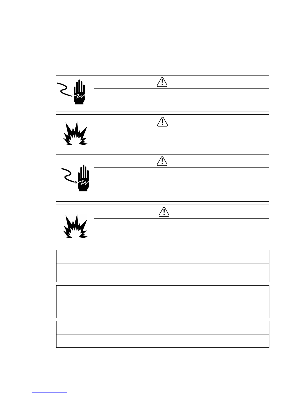
WARNING
FOR CONTINUED PROTECTION AGAINST SHOCK HAZARD CONNECT THE AC VERSION OF THE
IND246 TERMINAL TO PROPERLY GROUNDED OUTLET ONLY. DO NOT REMOVE THE GROUND
PRONG.
WARNING
DO NOT USE THE IND246 TERMINAL IN AREAS CLASSIFIED AS HAZARDOUS BECAUSE OF
COMBUSTIBLE OR EXPLOSIVE ATMOSPHERES. CONTACT AN AUTHORIZED METTLER TOLEDO
REPRESENTATIVE FOR INFORMATION ABOUT HAZARDOUS AREA APPLICATIONS.
WARNING
WHEN THIS EQUIPMENT IS INCLUDED AS A COMPONENT PART OF A SYSTEM, THE
RESULTING DESIGN MUST BE REVIEWED BY QUALIFIED PERSONNEL WHO ARE FAMILIAR
WITH THE CONSTRUCTION AND OPERATION OF ALL COMPONENTS IN THE SYSTEM AND THE
POTENTIAL HAZARDS INVOLVED. FAILURE TO OBSERVE THIS PRECAUTION COULD RESULT IN
BODILY HARM AND/OR PROPERTY DAMAGE.
CAUTION
THE BATTERY USED IN THIS DEVICE MAY PRESENT A RISK OF FIRE OR CHEMICAL BURN IF
MISTREATED. DO NOT CRUSH, DISASSEMBLE, HEAT ABOVE 60°C OR INCINERATE. REPLACE
BATTERY WITH 72253419 ONLY. USE OF ANOTHER BATTERY MAY PRESENT A RISK OF
BURN, FIRE OR EXPLOSION.
NOTICE
NiMH BATTERIES SLOWLY DISCHARGE WHEN NOT USED (FOR EXAMPLE WHEN STORED FOR FUTURE USE).
BATTERY OPERATED TERMINALS AND SPARE NiMH BATTERY PACKS IN STORAGE MUST BE FULLY CHARGED
EVERY THREE MONTHS TO PREVENT PERMANENT BATTERY DAMAGE.
NOTICE
DO NOT ATTEMPT TO CHARGE THE BATTERY IF THE BATTERY TEMPERATURE IS BELOW 0°C (32°F). CHARGING IS
NOT POSSIBLE AT OR BELOW THIS TEMPERATURE. DO NOT OPERATE THE BATTERY CHARGER OUTSIDE ITS
TEMPERATURE RANGE OF 0°C (32°F) TO 40°C (104°F).
DISPOSE OF USED BATTERY PROMPTLY. KEEP AWAY FROM CHILDREN. DO NOT DISASSEMBLE AND DO NOT
DISPOSE OF IN FIRE.
NOTICE

NOTICE
OBSERVE PRECAUTIONS FOR HANDLING ELECTROSTATIC SENSITIVE DEVICES.
Warnings and Cautions

64084448 / Rev. 03 / 12/2017
METTLER TOLEDO IND246 and IND246 POWERCELL Weighing Terminal User's Guide 1
Contents
1 Introduction ...................................................................... 1-1
1.1. IND246 Overview ............................................................... 1-1
1.1.1. Standard Features .................................................................................. 1-1
1.1.2. IND246 Terminal Versions ...................................................................... 1-2
1.2. Specifications .................................................................... 1-2
1.3. Battery Performance ........................................................... 1-5
1.4. Use in Hazardous Areas ...................................................... 1-6
1.5. Inspection and Contents Checklist ........................................ 1-6
1.6. Model Identification ............................................................ 1-7
1.7. Physical Dimensions .......................................................... 1-8
1.8. Main PCB .......................................................................... 1-9
1.8.1. SD Memory ........................................................................................... 1-9
1.9. Scale Bases ...................................................................... 1-9
1.9.1. Analog .................................................................................................. 1-9
1.9.2. POWERCELL .......................................................................................... 1-9
1.9.3. PowerDeck .......................................................................................... 1-10
1.10. Options ........................................................................... 1-10
1.10.1. COM2 Serial Port .................................................................................. 1-10
1.10.2. Discrete I/O .......................................................................................... 1-11
1.10.3. USB .................................................................................................... 1-11
1.10.4. Ethernet ............................................................................................... 1-11
1.11. Display and Keyboard ...................................................... 1-12
1.11.1. Display Layout ..................................................................................... 1-12
1.11.2. Front Panel Keys .................................................................................. 1-12
2 Operation: Terminal .......................................................... 2-1
2.1. Overview ........................................................................... 2-1
2.2. Display Elements and Keypad Operation ............................... 2-1
2.2.1. Display Elements ................................................................................... 2-1
2.2.2. Keypad Operation ................................................................................... 2-3
2.3. Operator Menu ................................................................... 2-6
2.3.1. Language Selection – F Codes ................................................................. 2-6
2.3.2. Menu Navigation .................................................................................... 2-6
2.3.3. Alibi Memory ......................................................................................... 2-9
2.3.4. Adjust Contrast ....................................................................................... 2-9
2.3.5. Transaction Counter .............................................................................. 2-10
2.3.6. Totals Memory ..................................................................................... 2-10
2.3.7. Expand x 10 ........................................................................................ 2-10
2.3.8. Information Recall ................................................................................ 2-11
2.3.9. Setup Access ....................................................................................... 2-12

2 METTLER TOLEDO IND246 and IND246 POWERCELL Weighing Terminal User's Guide
64084448 / Rev. 03 / 12/2017
2.4. Basic Functionality ........................................................... 2-12
2.4.1. Zero .................................................................................................... 2-12
2.4.2. Tare .................................................................................................... 2-13
2.4.3. Unit Switching ...................................................................................... 2-17
2.4.4. Expand By 10 ...................................................................................... 2-17
2.4.5. Print .................................................................................................... 2-17
2.4.6. Information Recall ................................................................................ 2-18
2.4.7. ID Entry ............................................................................................... 2-18
2.4.8. Time and Date ..................................................................................... 2-19
Contents
2.4.9. Totalization .......................................................................................... 2-19
2.4.10. Alibi Memory ....................................................................................... 2-19
2.5. Applications .................................................................... 2-20
2.5.1. Animal Weighing .................................................................................. 2-20
2.5.2. Checkweighing .................................................................................... 2-20
2.5.3. Counting ............................................................................................. 2-21
2.5.4. Peak Weight ........................................................................................ 2-21
2.5.5. Vehicle Weighing ................................................................................. 2-22
3 Configuration: Terminal ..................................................... 3-1
3.1. Entering Setup Mode ........................................................... 3-1
3.2. Security ............................................................................. 3-1
3.3. Exiting Setup Mode ............................................................. 3-2
3.4. Setup Menu Structure .......................................................... 3-2
3.4.1. Navigation ............................................................................................. 3-2
3.4.2. Setup Page ............................................................................................ 3-2
3.5. Configuration: Overview ...................................................... 3-5
3.6. Configuration: Scale ........................................................... 3-6
3.6.1. Type ..................................................................................................... 3-6
3.6.2. Load Cell ............................................................................................... 3-7
3.6.3. Capacity and Increment ........................................................................ 3-11
3.6.4. Calibration ........................................................................................... 3-13
3.6.5. Zero .................................................................................................... 3-14
3.6.6. Tare .................................................................................................... 3-15
3.6.7. Units ................................................................................................... 3-17
3.6.8. Filter ................................................................................................... 3-17
3.6.9. Stability ............................................................................................... 3-18
3.6.10. Log or Print ......................................................................................... 3-18
3.6.11. Scale Reset .......................................................................................... 3-19
3.7. Configuration: Application ................................................. 3-20
3.7.1. Memory............................................................................................... 3-20
3.7.2. Totalization .......................................................................................... 3-20
3.7.3. Discrete I/O .......................................................................................... 3-21
3.7.4. Function Key ........................................................................................ 3-21
3.7.5. Animal Weighing .................................................................................. 3-22

64084448 / Rev. 03 / 12/2017
METTLER TOLEDO IND246 and IND246 POWERCELL Weighing Terminal User's Guide 3
3.7.6. Counting ............................................................................................. 3-23
3.7.7. Checkweighing .................................................................................... 3-24
3.7.8. Peak Weight ........................................................................................ 3-25
3.7.9. Vehicle Weighing ................................................................................. 3-26
3.7.10. Reset .................................................................................................. 3-26
3.8. Configuration: Terminal ..................................................... 3-27
3.8.1. Device ................................................................................................. 3-27
3.8.2. Display ............................................................................................... 3-27
3.8.3. Region ................................................................................................ 3-28
3.8.4. Transaction Counter .............................................................................. 3-30
3.8.5. User .................................................................................................... 3-30
3.8.6. Menu Keys .......................................................................................... 3-30
3.8.7. Reset .................................................................................................. 3-31
3.9. Configuration: Communication ........................................... 3-31
3.9.1. Templates............................................................................................ 3-31
3.9.2. Reports ............................................................................................... 3-33
3.9.3. Connections ........................................................................................ 3-33
3.9.4. Serial .................................................................................................. 3-36
3.9.5. Network............................................................................................... 3-38
3.9.6. Reset .................................................................................................. 3-39
3.10. Configuration: Maintenance ............................................... 3-39
3.10.1. Diagnostics ......................................................................................... 3-39
3.10.2. Scale .................................................................................................. 3-39
3.10.3. Replace Battery .................................................................................... 3-47
3.10.4. Install Software Update .......................................................................... 3-47
3.10.5. Backup to SD ....................................................................................... 3-47
3.10.6. Restore from SD ................................................................................... 3-47
3.10.7. POWERCELL Maintenance ..................................................................... 3-47
3.10.8. Reset All - Factory Default Settings.......................................................... 3-52
3.11. Restoring Factory Default Settings ....................................... 3-52
4 Applications: Configuration and Operation .......................... 4-1
4.1. Introduction ....................................................................... 4-1
4.2. Animal Weighing ................................................................ 4-1
4.2.1. Overview ............................................................................................... 4-1
4.2.2. Operational Features ............................................................................... 4-2
4.2.3. Configuration ......................................................................................... 4-3
4.2.4. Operating Sequence ................................................................................ 4-4
4.2.5. Remote Displays .................................................................................... 4-6
4.2.6. Serial Input Commands ........................................................................... 4-6
4.2.7. Print Formats ......................................................................................... 4-6
4.3. Checkweighing (Over/Under) ............................................... 4-8
4.3.1. Overview ............................................................................................... 4-8
4.3.2. Operational Features ............................................................................... 4-8
4.3.3. Configuration ......................................................................................... 4-9

4 METTLER TOLEDO IND246 and IND246 POWERCELL Weighing Terminal User's Guide
64084448 / Rev. 03 / 12/2017
4.3.4. Operating Sequence .............................................................................. 4-14
4.3.5. Print Formats ....................................................................................... 4-18
4.4. Counting ......................................................................... 4-20
4.4.1. Overview ............................................................................................. 4-20
4.4.2. Operational Features ............................................................................. 4-21
4.4.3. Configuration ....................................................................................... 4-21
4.4.4. Operating Sequences ............................................................................ 4-24
4.4.5. Print Formats ....................................................................................... 4-28
4.5. Peak Weight Measurement ................................................ 4-30
Contents
4.5.1. Overview ............................................................................................. 4-30
4.5.2. Operational Features ............................................................................. 4-30
4.5.3. Configuration ....................................................................................... 4-31
4.5.4. Operating Sequences ............................................................................ 4-32
4.5.5. Memory Operation ................................................................................ 4-34
4.5.6. Print Formats ....................................................................................... 4-35
4.6. Vehicle Weighing ............................................................. 4-37
4.6.1. Overview ............................................................................................. 4-37
4.6.2. Operational Features ............................................................................. 4-38
4.6.3. Configuration ....................................................................................... 4-38
4.6.4. Operating Sequences ............................................................................ 4-42
4.6.5. Print Formats ....................................................................................... 4-47
5 Service and Maintenance .................................................. 5-1
5.1. Cleaning and Maintenance .................................................. 5-1
5.2. Service .............................................................................. 5-1
5.3. Battery Operation ................................................................ 5-2
5.3.1. Specifications ........................................................................................ 5-2
5.3.2. Battery Status Icon .................................................................................. 5-3
5.3.3. Accessing the Battery Pack ...................................................................... 5-3
5.3.4. Charging the Battery Pack ....................................................................... 5-5
5.3.5. Disposing of a Depleted Battery Pack ....................................................... 5-7
5.4. Troubleshooting ................................................................. 5-7
5.4.1. Blank Display ........................................................................................ 5-7
5.4.2. Power Test............................................................................................. 5-8
5.4.3. Problem Diagnosis ................................................................................. 5-8
5.4.4. Error Codes and Error Messages .............................................................. 5-9
5.4.5. Internal Diagnostics .............................................................................. 5-11
5.5. Replacing BRAM Battery .................................................... 5-14
5.6. System Backup and Restore .............................................. 5-15
5.6.1. Files, Media and Data ........................................................................... 5-15
5.6.2. Backup to SD Memory Card ................................................................... 5-16
5.6.3. Restore from SD Memory Card ............................................................... 5-16
5.7. Master Reset .................................................................... 5-17

64084448 / Rev. 03 / 12/2017
METTLER TOLEDO IND246 and IND246 POWERCELL Weighing Terminal User's Guide 5
5.8. Upgrading Firmware ......................................................... 5-18
5.9. Board and Display Replacement ........................................ 5-18
5.9.1. Option Board Removal .......................................................................... 5-19
5.9.2. Main Board Removal ............................................................................ 5-19
5.9.3. Display Module Removal ...................................................................... 5-21
5.9.4. Display Module Installation ................................................................... 5-22
5.9.5. Main PCB Installation ........................................................................... 5-22
5.9.6. Option PCB Installation ......................................................................... 5-22
5.9.7. Final Steps........................................................................................... 5-23
A Default Templates ............................................................. A-1
A.1. Basic Functionality ............................................................. A-1
A.2. Vehicle Application ............................................................. A-2
A.3. Checkweighing Application .................................................. A-3
A.4. Peak Weight Application ..................................................... A-4
A.5. Animal Weighing Application ............................................... A-5
A.6. Counting Application ........................................................... A-5
B Parameter Values ............................................................. B-1
B.1. Scale Block, IND246 Analog ............................................... B-1
B.2. Scale Block, IND246 POWERCELL ....................................... B-5
B.3. Application Block ............................................................... B-8
B.4. Terminal Block ................................................................. B-15
B.5. Communications Block ..................................................... B-18
B.6. Maintenance Block, IND246 Analog ................................... B-24
B.7. Maintenance Block, IND246 POWERCELL ........................... B-26
C Alibi Memory .................................................................... C-1
C.1. Viewing Alibi Memory Records ............................................. C-1
C.2. Printing Alibi Memory Records ............................................. C-2
C.3. Alibi Memory Print Formats .................................................. C-3
C.3.1. Narrow Format, * Record Separator .......................................................... C-3
C.3.2. Wide Format, = Record Separator ............................................................ C-3
D Communications ............................................................... D-1
D.1. Serial Interface Parameters .................................................. D-1
D.2. Demand Output Mode ......................................................... D-2
D.2.1. Output Templates ................................................................................... D-2
D.3. Continuous Output Mode ..................................................... D-3
D.3.1. Standard Continuous Output .................................................................... D-3
D.3.2. Continuous Output in Animal Weighing ..................................................... D-5
D.3.3. Continuous – Extended Output ................................................................. D-5

6 METTLER TOLEDO IND246 and IND246 POWERCELL Weighing Terminal User's Guide
64084448 / Rev. 03 / 12/2017
D.3.4. Multi-Continuous Out .............................................................................. D-8
D.4. Scoreboard Displays ......................................................... D-11
D.4.1. Continuous Output ................................................................................ D-12
D.4.2. Continuous Multi-1 Output ..................................................................... D-12
D.5. CTPZ .............................................................................. D-13
D.6. Standard Interface Command Set (SICS) Protocol ................. D-14
D.6.1. Version Number of the MT-SICS.............................................................. D-14
D.6.2. Command Formats ............................................................................... D-14
D.6.3. Response Formats ................................................................................ D-15
Contents
D.6.4. Tips for the Programmer ........................................................................ D-16
D.6.5. Commands and Responses MT-SICS Level 0 .......................................... D-16
D.6.6. Commands and Responses MT-SICS Level 1 .......................................... D-20
D.7. Reports ........................................................................... D-23
D.7.1. Alibi Memory ....................................................................................... D-23
D.7.2. Totals Report ....................................................................................... D-24
D.8. Variable Access ................................................................ D-24
D.8.1. Connection .......................................................................................... D-24
D.8.2. Commands ......................................................................................... D-24
D.8.3. Variable List ......................................................................................... D-26
E GEO Codes ....................................................................... E-1
E.1. Original Site Calibration ....................................................... E-1
E.2. New Site GEO Code Adjustment ............................................ E-1

64084448 | 03 | 12/2017
METTLER TOLEDO IND246 and IND246 POWERCELL User's Guide
1-1
This chapter covers
1 Introduction
The IND246 and IND246 POWERCELL industrial scale terminals provide a
• Overview
• Specifications
• Use in Hazardous Areas
• Safe Disposal Requirement
• Inspection and Contents
Checklist
• Model Identification
• Physical Dimensions
• Main PCB
• Scale Bases
• Options
• Display and Keyboard
Standard applications include basic weighing, animal weighing, check weighing, counting, peak
weight measurement and vehicle weighing. Whether communicating weight data to a PC or
providing a serial output of data to a printer, the IND246 terminal offers solutions for a wide range
of applications.
compact yet flexible solution to a variety of weighing needs. Available as either AC
powered for stationary applications or battery-powered for portable analog load cell
applications, this terminal is at home in virtually any industrial environment.
Innovative use of Secure Data (SD) Memory technology expands the memory
available for data storage when required.
Unless stated otherwise, IND246 refers to both the analog and POWERCELL
versions.
Both 2mv/V and 3mv/V analog load cells are supported without the need for
any configuration change. The POWERCELL model supports the advanced
capabilities of POWERCELL PDX and GDD load cells, featuring sophisticated selfdiagnostics. The PowerDeck model for POWERCELL supports a connector for quick
home run cable termination, faster calibration and automatic addressing. The
IND246 delivers precision measurement data from grams to tons in a single, cost
effective package.
1.1. IND246 Overview
1.1.1. Standard Features
• Rugged stainless steel enclosure
• Supports one analog load cell platform with up to four (battery version), ten (AC version)
350Ω load cells; or one scale platform with up to 12 POWERCELL PDX load cells; or up to 3
PowerDeck scale platforms, each with 4 SLB615D load cells; or up to 12 SLC611D LCWM
load cells
• Large transflective graphic LCD display with backlight for vivid readability in all light
conditions
• One electrically isolated serial port (COM1) for asynchronous, bidirectional communication
• Powered by either 85–264 V AC or internal battery pack (selected by model)
• Support for the following option boards:
Choice of one serial/DIO option:

1-2
METTLER TOLEDO IND246 and IND246 POWERCELL User's Guide
64084448 | 03 | 12/2017
Enclosure Type
Dimensions (w ×
h × d)
Shipping Weight
o COM2 Serial Interface
o COM2 and Discrete I/O interface (analog version only)
o USB Serial Interface
o USB and Discrete I/O interface (analog version only)
Optional network interface:
o Ethernet TCP/IP
• Front panel key access to basic weighing functions – zero, tare, clear, unit switching and
print
• Alpha numeric keypad for simple, quick entry of tare and identification information
Introduction
• Selectable primary unit of measure including grams, kilograms, pounds, tons, metric tons
• Selectable second unit of measure including grams, kilograms, pounds, ounces, tons and
metric tons
• Backup and restore of configuration and calibration settings, using SD memory device or
• PC-based File Transfer Tool (included) exchanges application files and tables with the
®
SL PC tool (included)
InSite
IND246 terminal
• Automatic shutoff and backlight timeout features to help conserve energy on the battery
powered version
1.1.2. IND246 Terminal Versions
The terminal is available in the following four versions:
• IND246 Harsh enclosure, AC power
• IND246 Harsh enclosure, Battery power
• IND246 POWERCELL, AC power
• IND246 POWERCELL for SL_61xD, AC power
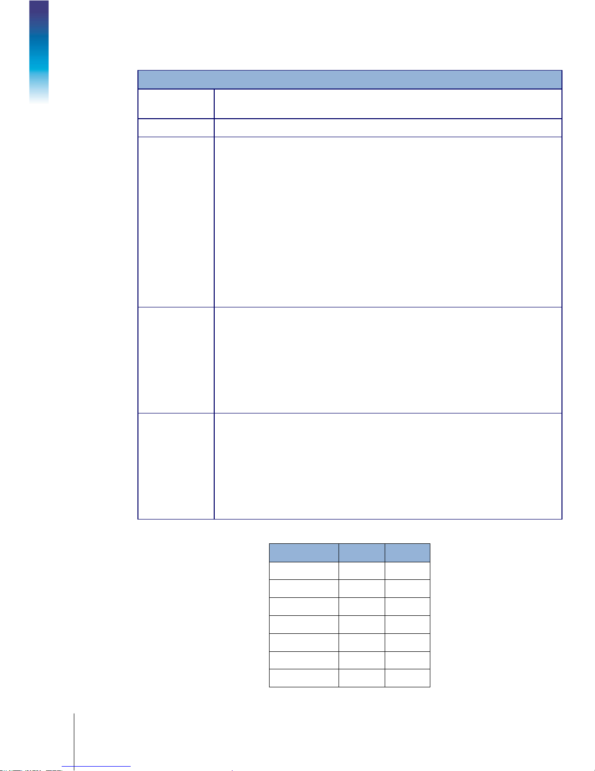
1.2. Specifications
The IND246 terminal conforms to the specifications listed in Table 1-1.
Table 1-1: Terminal Specifications
Stainless steel, configurable as desk top or wall mount enclosure
230 mm x 146 mm x 165 mm (9 in. x 5.75 in. x 6.5 in.)
AC Version: 3.4 kg (7.5 lb)
Battery Version: 3.9 kg (8.5 lb)
POWERCELL Version: 3.6 kg (7.9 lb)
IND246 Specifications

64084448 | 03 | 12/2017
METTLER TOLEDO IND246 and IND246 POWERCELL User's Guide
1-3
IND246 Specifications
Environmental
Protection
Operating
Environment
Hazardous Areas
Power
Power
Consumption
Power
Consumption
Display
Weight Display
Scale Types
Number of Cells
Number of Scales
Analog
Update Rate
POWERCELL
Update Rate
Update Rates (Hz)
Update Rate, Type
Synchronized Continuous Weight
Load Cell
Excitation Voltage
IP66 (comparable to Type 4x)
The terminal can be operated at temperatures ranging from −10° to 40° C (14° to
104° F) at 10% to 95% relative humidity, non-condensing.
The IND246 terminal cannot be operated in areas classified as Hazardous because of
combustible or explosive atmospheres in those areas. Contact an authorized METTLER
TOLEDO representative for information about hazardous area applications.
AC version: Operates at 85–264 VAC, 49–61 Hz and includes a power cord configured
for the country of use.
Battery version: Operates from internal NiMH battery pack
Refer to Table 1-2 for details of the AC version. Values shown are with internal COM2/DIO
option and Ethernet option installed and load cell input loaded with 8 x 350Ω load cells.
Refer to Table 1-3 for Refer to Table 1-4 for details of the battery life for the battery
powered version.
Refer to Table 1-2 for the AC version; Table 1-3 for IND246 POWERCELL; and Table 1-4
for the battery version.
Values shown in Table 1-2 are for an IND246 terminal with the internal COM2/DIO and
Ethernet options installed, and input from 8 x 350Ω load cells.
Backlit 240 x 96 dot graphic LCD including weight display, weight units, gross/net
indication and graphic symbols for motion and center of zero, SmartTrac, operator
prompts and data entry display. Update rate of 12 updates per second.
Basic weight mode: 27 mm (1.1 in) high weight display
Application mode: 20 mm (0.8 in) high weight display
Maximum displayed resolution of 50,000 divisions.
Analog load cells (AC or battery models), POWERCELL PDX, GDD, SLC611D or
SLD615D load cells (POWERCELL model),
AC Version: From one to ten 350-ohm load cells (2 or 3 mV/V)
Battery Version: From one to four 350-ohm load cells (2 or 3 mV/V)
POWERCELL Version: Up to 12 POWERCELL PDX, GDD, SLC611D or SLB615D load cells
One
Internal analog: 366 MHz
Vehicle, 12 load cells
Load Cell Network 25
Output
USB, COM1,
COM2, Ethernet
17 - 25
AC Version: 10 VDC
Battery Version : 5 V DC
1-4
METTLER TOLEDO IND246 and IND246 POWERCELL User's Guide
64084448 | 03 | 12/2017
Minimum
Sensitivity
Keypad
Communications
Approvals,
Analog Version
Approvals,
POWERCELL
Version
IND246 Specifications
0.1 microvolt per increment
25 keys; polyester overlay (PET) with polycarbonate display lens
Serial Interfaces
Standard: One isolated serial port (COM1) RS-232 (analog only); RS-232/RS-422-
RS-485 (POWERCELL only), 300 to 115,200 baud
Optional isolated serial port: (COM2) RS-232/485, 300 to 115,200 baud
Optional USB port: serial port bridge, 300 to 115,200 baud
Introduction
Ethernet Interface
Optional Ethernet port: 10/100 TCP/IP port
Protocol
Serial Inputs: ASCII commands for CTPZ (Clear, Tare, Print, Zero), SICS (most level 0
and level 1 commands)
Serial Outputs: Continuous, Extended continuous, Demand (limited formats), Reports,
SICS (most level 0 and level 1 commands) or Variable Access
Weights and Measures
USA: NTEP Class III/IIIL - 10,000d; Cert. #11-040
Canada: Class III - 10,000d; Class IIIHD - 20,000d; AM-5819
Europe: Class III 6000e, Class IIII 1000e; TC7918, T8030
OIML: Class III 6000e, Class IIII 1000e; R76/2006-NL1-15.49R1
Product Safety
UL, cUL, CE
Weights and Measures
USA: : NTEP Class III/IIIL - 10,000d; Cert. #11-040
Canada: Class III - 10,000d; Class IIIHD - 20,000d; AM-5819
Europe: Class III 6000e, Class IIII 1000e; TC7918, T8426
OIML: Class III 6000e, Class IIII 1000e; R76/2006-NL1-15.49R1
Product Safety
UL, cUL, CE
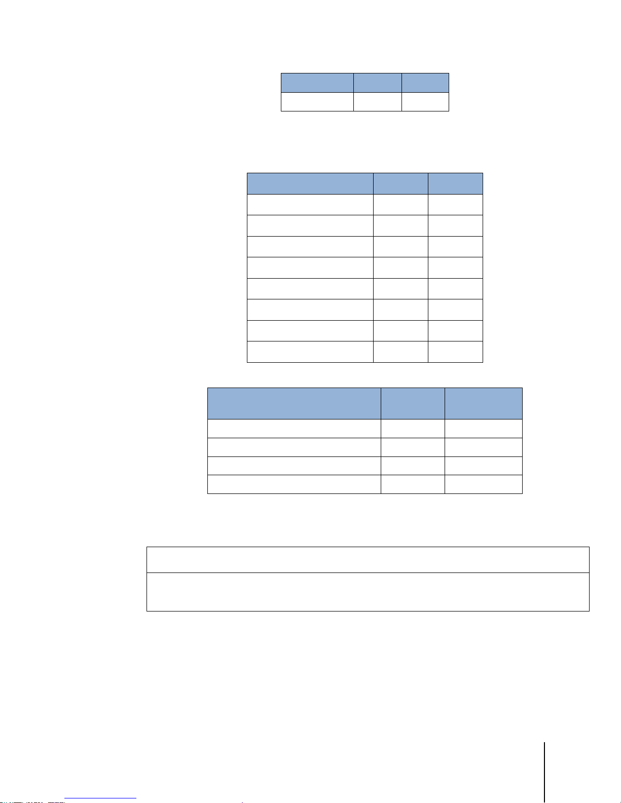
Table 1-2: IND246 Power Consumption (AC Source)
Input Voltage I (mA) P (W)
85V/50 Hz 167 7.9
110 V/50 Hz 133 7.7
240 V/50 Hz 64 7.9
264 V/50 Hz 59 7.9
85 V/60 Hz 163 7.9
110 V/60 Hz 128 7.7
240 V/60 Hz 62 7.9
64084448 | 03 | 12/2017
METTLER TOLEDO IND246 and IND246 POWERCELL User's Guide
1-5
Input Voltage I (mA) P (W)
264 V/60 Hz 58 8.0
Values shown are with internal COM2/DIO option and Ethernet option installed and load cell input
loaded with 8 x 350Ω load cells.
Table 1-3: Power Consumption for POWERCELL Version
Input Voltage I(mA) P(W)
85V/50Hz 112 5.7
110V/50Hz 94 6
240V/50Hz 73 8.4
264V/50Hz 72 8.7
85V/60Hz 108 5.8
110V/60Hz 92 6
240V/60Hz 73 8.3
264V/60Hz 73 8.6
Table 1-4: IND246 Average Battery Life, Analog Version
Continuous Operation Load
1- 350Ω cell, no options 21.5 hrs 49 hrs
1 – 350Ω cell, COM2/DIO option 12.5 hrs 19 hrs
4 – 350Ω cells, no options 17. 5 hrs 32 hrs
4 – 350Ω cells, COM2/DIO option 11 hrs 15.5 hrs
1.3. Battery Performance
NiMH BATTERIES SLOWLY DISCHARGE WHEN NOT USED (FOR EXAMPLE WHEN STORED FOR FUTURE USE).
BATTERY OPERATED TERMINALS AND SPARE NiMH BATTERY PACKS IN STORAGE MUST BE FULLY CHARGED EVERY
THREE MONTHS TO PREVENT PERMANENT BATTERY DAMAGE.
Battery Life
w/Backlight
NOTICE
Battery Life w/o
Backlight

1-6
METTLER TOLEDO IND246 and IND246 POWERCELL User's Guide
64084448 | 03 | 12/2017
• IND246 Terminal
• Safety Instructions
1.4. Use in Hazardous Areas
WARNING
DO NOT USE THE IND246 TERMINAL IN AREAS CLASSIFIED AS HAZARDOUS BECAUSE OF
COMBUSTIBLE OR EXPLOSIVE ATMOSPHERES. CONTACT AN AUTHORIZED METTLER TOLEDO
REPRESENTATIVE FOR INFORMATION ABOUT HAZARDOUS AREA APPLICATIONS.
1.5. Inspection and Contents Checklist
Introduction
Verify the contents and inspect the package immediately upon delivery. If the shipping container is
damaged, check for internal damage and file a freight claim with the carrier if necessary. If the
container is not damaged, remove the terminal from its protective package, noting how it was
packed, and inspect each component for damage.
If shipping the terminal is required, it is best to use the original shipping container. The terminal
must be packed correctly to ensure its safe transportation.
The package should include:
• Battery Pack (battery version only)
• Mounting brackets (2; analog version only)
• Resource CD (includes all manuals)
• Bag of miscellaneous parts
64084448 | 03 | 12/2017
METTLER TOLEDO IND246 and IND246 POWERCELL User's Guide
1-7
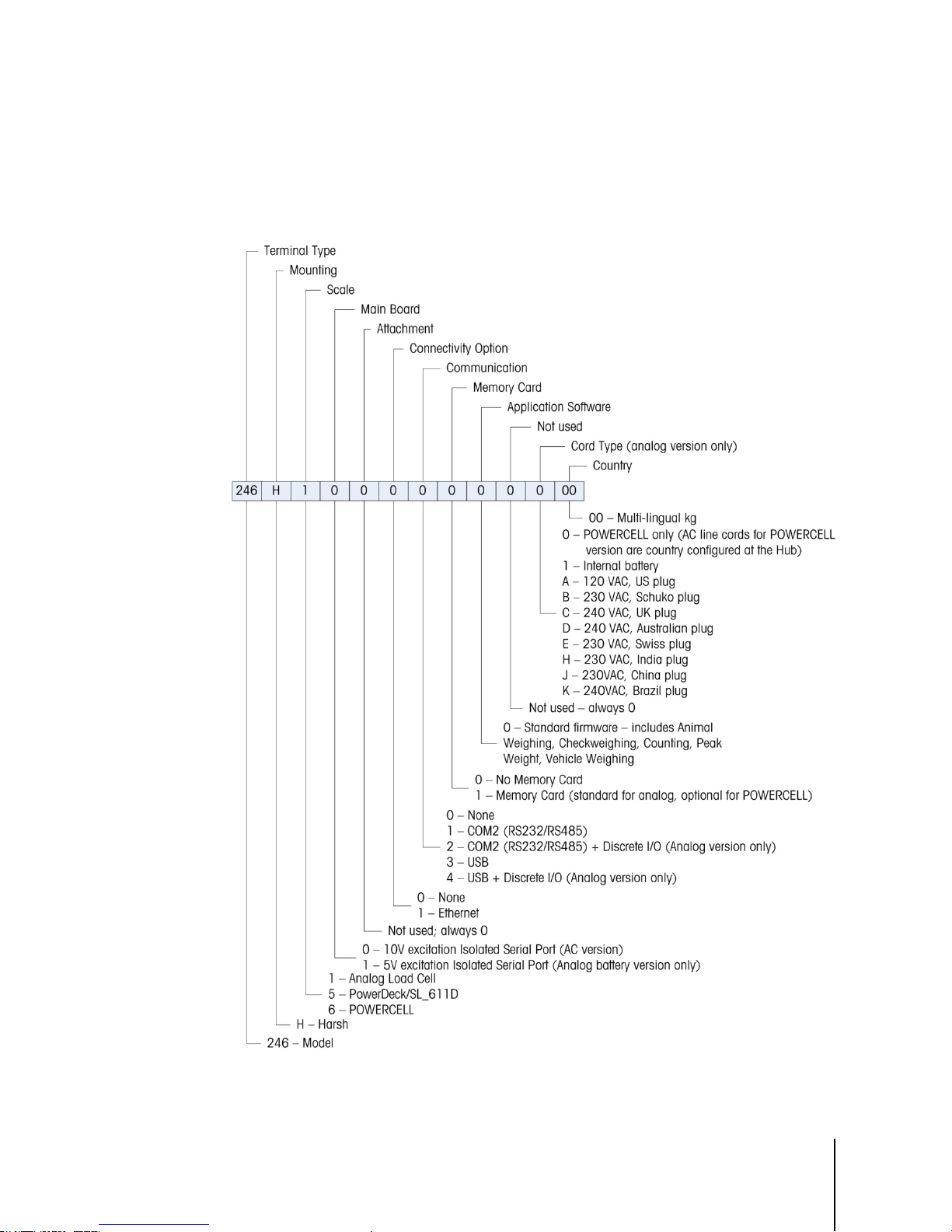
1.6. Model Identification
The IND246 and IND246 POWERCELL model number, factory number and serial number are
located on the data plate of the terminal. Refer to Figure 1-1 to verify the configuration of the
IND246 terminal when it left the METTLER TOLEDO factory.
Figure 1-1: IND246 Configuration Chart
1-8
METTLER TOLEDO IND246 and IND246 POWERCELL User's Guide
64084448 | 03 | 12/2017
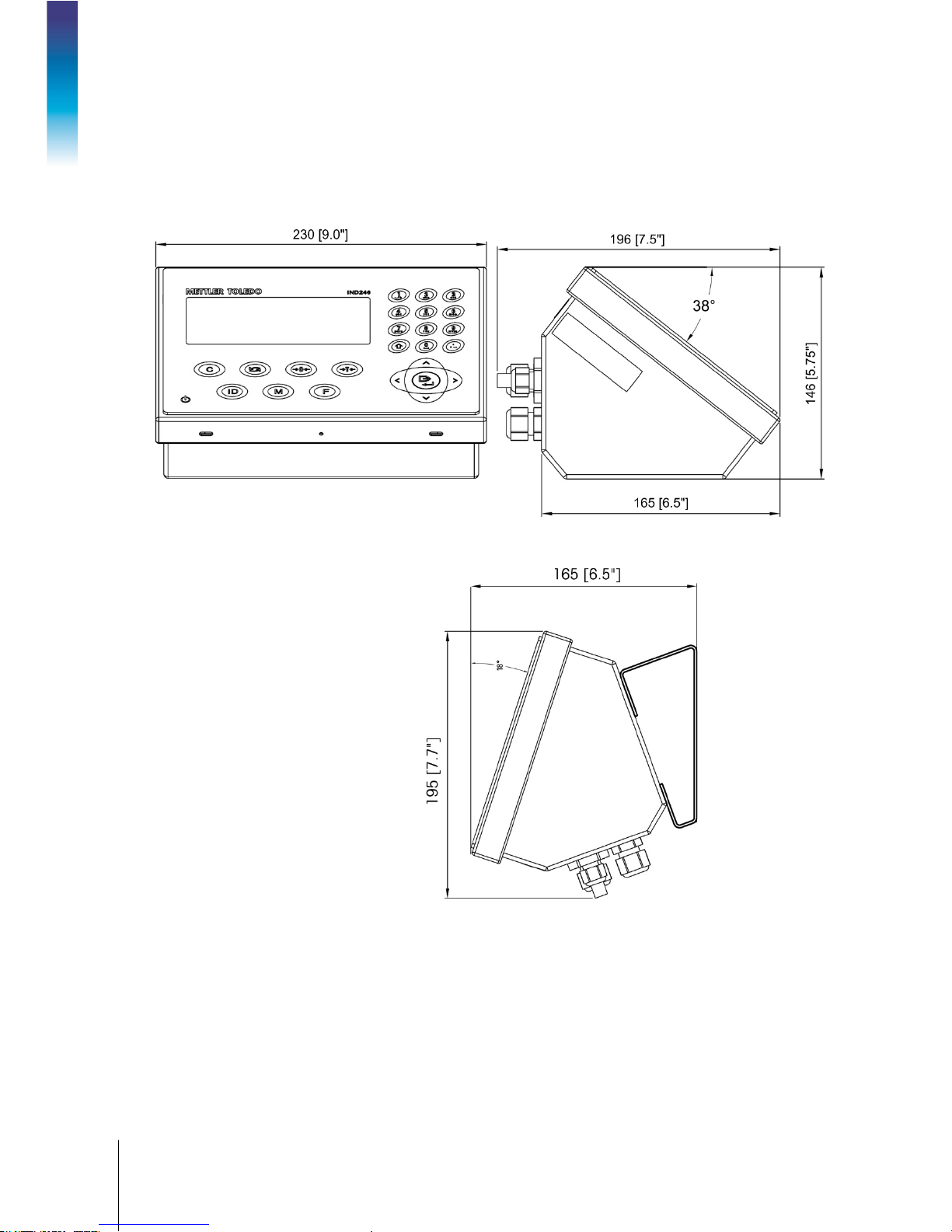
1.7. Physical Dimensions
The physical dimensions of the IND246 enclosure are shown in Figure 1-2 and Figure 1-3 in mm
and [inches].
Introduction
Figure 1-2: IND246 Enclosure Dimensions
Figure 1-3: IND246 Dimensions with Brackets

64084448 | 03 | 12/2017
METTLER TOLEDO IND246 and IND246 POWERCELL User's Guide
1-9
1.8. Main PCB
The IND246 terminal’s main printed circuit board (PCB) provides the analog load cell scale
interface, as well as the COM1 RS-232 serial port. The IND246 POWERCELL main board provides
the load cell interface and a standard COM1 RS-232/RS-422/RS-485 isolated serial port.
The main board also contains the power input connection (for either AC supply or battery,
depending on the model), display interface, keypad interface and six-position DIP switch.
An SD memory card socket is mounted to the PCB to support the optional SD memory and bus
connectors are included for the option boards.
1.8.1. SD Memory
An SD Memory card is included as a standard feature of the analog version of the IND246, and is
available as an option for the POWERCELL version. The card provides a medium on which to store
files such as Alibi memory, transaction records in the vehicle application, IDs in the counting
application and target weights in the checkweighing application.
The SD memory can be used to extract and save the configuration and calibration settings of the
terminal. These can then be restored to the terminal or loaded to a different terminal.
1.9. Scale Bases
1.9.1. Analog
The standard IND246 terminal supports analog scale bases and provides either 10 volts (AC
version) or 5 volts (battery version) of excitation to drive analog load cells. Up to four (battery
version) or ten (AC version) 350Ω load cells can be powered by the terminal.
A six wire load cell connection is provided with sense lines to help maintain accuracy as the load
cell cable resistance changes with temperature variations.
1.9.2. POWERCELL
The IND246 POWERCELL terminal supports scale bases that use POWERCELL PDX, GDD,
SLC611D or SLB615D load cells. Up to 12 load cells can be configured in a single scale platform.
The load cell network provides monitoring and logging of a variety of factors that can affect system
integrity, including weighing errors, overloads and network health. The specific characteristics differ
by type of load cell.

1-10
METTLER TOLEDO IND246 and IND246 POWERCELL User's Guide
64084448 | 03 | 12/2017
1.9.3. PowerDeck
The IND246 POWERCELL supports PowerDeckTM weighing platforms. These provide calibration
without weights for fast installation and visual guidance for leveling the floor platform.
Introduction
Figure 1-4: IND246 POWERCELL with PowerDeck Platform
1.10. Options
The following options are available for all versions of the IND246:
• COM2 Serial Port
One RS-232/485 isolated serial COM port
COM2 and DIO (relay output)
•
One RS-232/485 isolated serial COM port
Internal, discrete I/O (2 inputs and 4 outputs; supported in analog version only)
─ Inputs are optically isolated solid state and switch selectable as either active or passive
─ Output relays provide one normally open contact per relay
•
USB Port
One USB 2.0 compliant port, hardware bridge. Acts as virtual (UCP) COM port
USB and DIO (relay output)
•
One USB 2.0 compliant port, hardware bridge. Acts as virtual (UCP) COM port
Internal, discrete I/O (2 inputs and 4 outputs; supported in analog version only)
─ Inputs are optically isolated solid state and switch selectable as either active or passive
─ Output relays provide one normally open contact per relay
•
Ethernet Port
One 10/100 Ethernet port with automatic link polarity detection and correction. Supports TCP/IP socket
connection. Does not support FTP
1.10.1. COM2 Serial Port
This optional port provides RS-232 and RS-485 communication at rates from 300 to 115.2k baud.
The port is bidirectional and can be configured for various functions such as demand output,
continuous output, extended continuous output, SICS host communications or ASCII command
input (C, T, P, Z).

64084448 | 03 | 12/2017
METTLER TOLEDO IND246 and IND246 POWERCELL User's Guide
1-11
The COM2 port is galvanically isolated for both RS-232 and RS-485, to provide surge voltage
protection.
The RS-485 connection can be used as an RS-422 transmit only when sending continuous output
to a scoreboard or remote display.
1.10.2. Discrete I/O
The Discrete I/O option is supported only in the analog version of the IND246.
The discrete I/O interface option provides dry-contact relay outputs. The relay contacts will switch up
to 30 volts DC or 250 volts AC at 1A.
The inputs are switch selectable as either active (for simple pushbutton control) or passive (for
connection to devices that supply their own power for the inputs).
1.10.3. USB
The USB port provided is a hardware bridge acting as a virtual COM port, and is used for
conversion of serial data. The port is bidirectional and can be configured for various functions such
as demand output, continuous output, extended continuous output, SICS host communications or
ASCII command input (C, T, P, Z).
1.10.4. Ethernet
The IND246 Ethernet option provides an RJ45 jack for connection to an Ethernet network or host
device. A TCP socket connection can be made to port 1701 to transfer files or to exchange data
with a PC. This port can also operate as a print client to send data to a network printer.
1-12
METTLER TOLEDO IND246 and IND246 POWERCELL User's Guide
64084448 | 03 | 12/2017
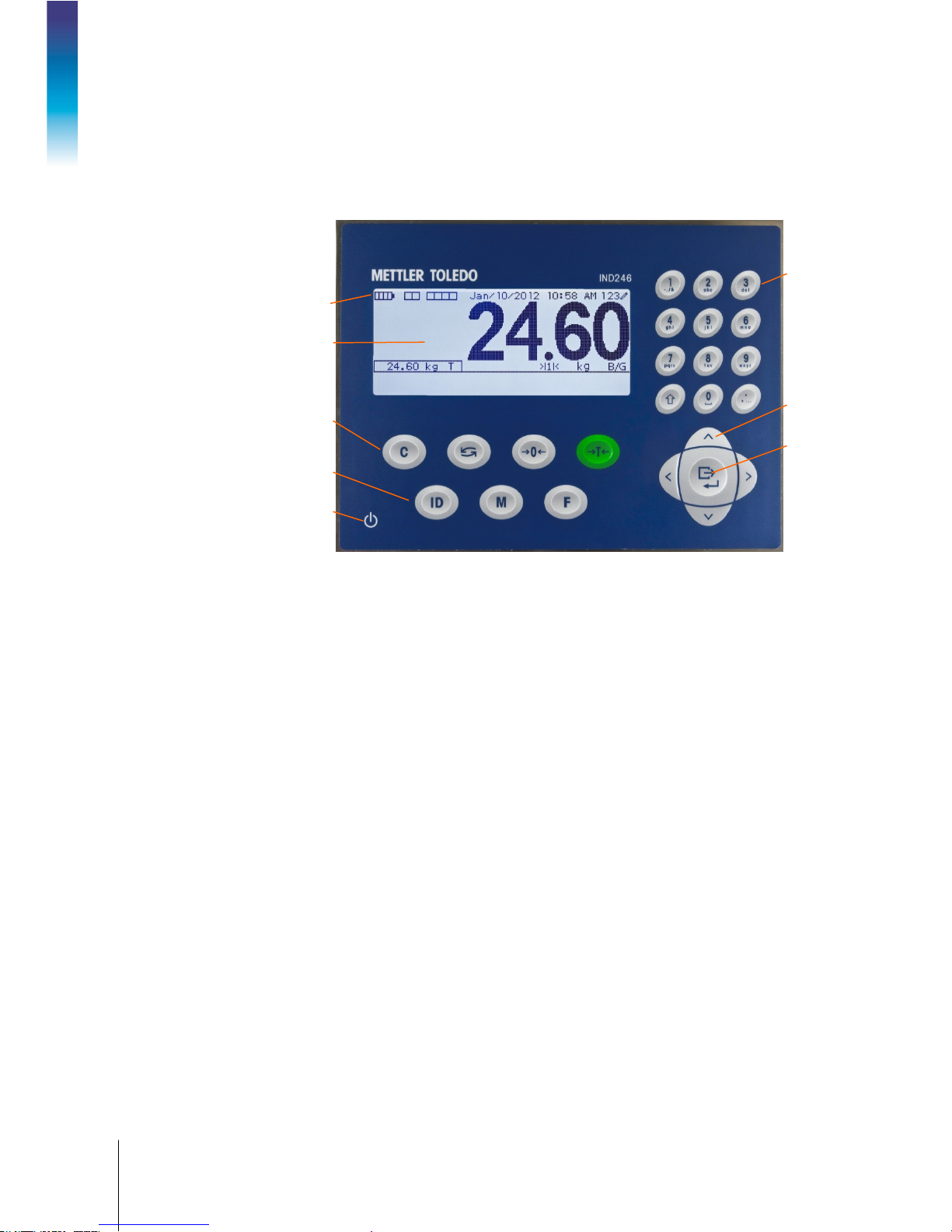
System line
1.11. Display and Keyboard
The IND246 terminal uses a graphic, transflective type Liquid Crystal Display (LCD) with a white
LED backlight. The front panel including the display and keypad is shown in Figure 1-4.
Alphanumeric
keypad
Introduction
Scale Function keys
1.11.1. Display Layout
At the top of the display, a single system line displays terminal status and operator error displays
and messages. Time and date and the status of the Digital I/O can be displayed in this area, when
so configured in setup.
Below the system line is the weight display. During normal, basic weighing operation, the IND246
terminal display shows the Gross or Net weight in the larger 28.5mm (1.1 in.) size. When one of
the applications is running, the weight is shown in 20mm (0.8 in.) high characters. Below the
weight display is a single line to display the weight units, the weight legend, the center of zero icon,
weight range and motion icon. Tare values also appear on this line, to the left of the display.
LCD display
Navigation
keys
Print/Enter key
Operational
keys
ON/OFF key
Figure 1-5: IND246 Front Panel Layout
At the bottom of the normal basic weighing display is a line used for data entry. For display
operation during setup, refer to Chapter 3,
1.11.2. Front Panel Keys
The IND246 terminal provides a total of 25 keys as operator interfaces. The ON/OFF key, four scale
function keys and three operational keys are positioned under the display while the alpha-numeric
keys are positioned to the right of the display. The print/enter key and navigation keys are located at
the bottom right of the display. These keys are used to enter the setup menu, to navigate and select
setup elements, and to enter values in setup as described in Chapter 3,
Configuration.
Configuration.

64084448 | 03 | 10/2017
METTLER TOLEDO IND246 and IND246 POWERCELL User's Guide
2-1
This chapter covers
2 Operation: Terminal
2.1. Overview
This chapter provides information about the basic functionality of the IND246 terminal,
• Overview
• Basic Functionality
• Display Operation
• Keypad Operation
• Operator Menu
• Applications
2.2. Display Elements and Keypad Operation
Refer to Figure 1-4 for an over view of the layout of the front panel of the IND246.
2.2.1. Display Elements
including display operation, keypad functions and menu navigation.
Operation of the terminal varies depending on which functions are enabled, and on the
configuration of parameters in setup. Configuration is described in Chapter 3,
Terminal.
Configuration:
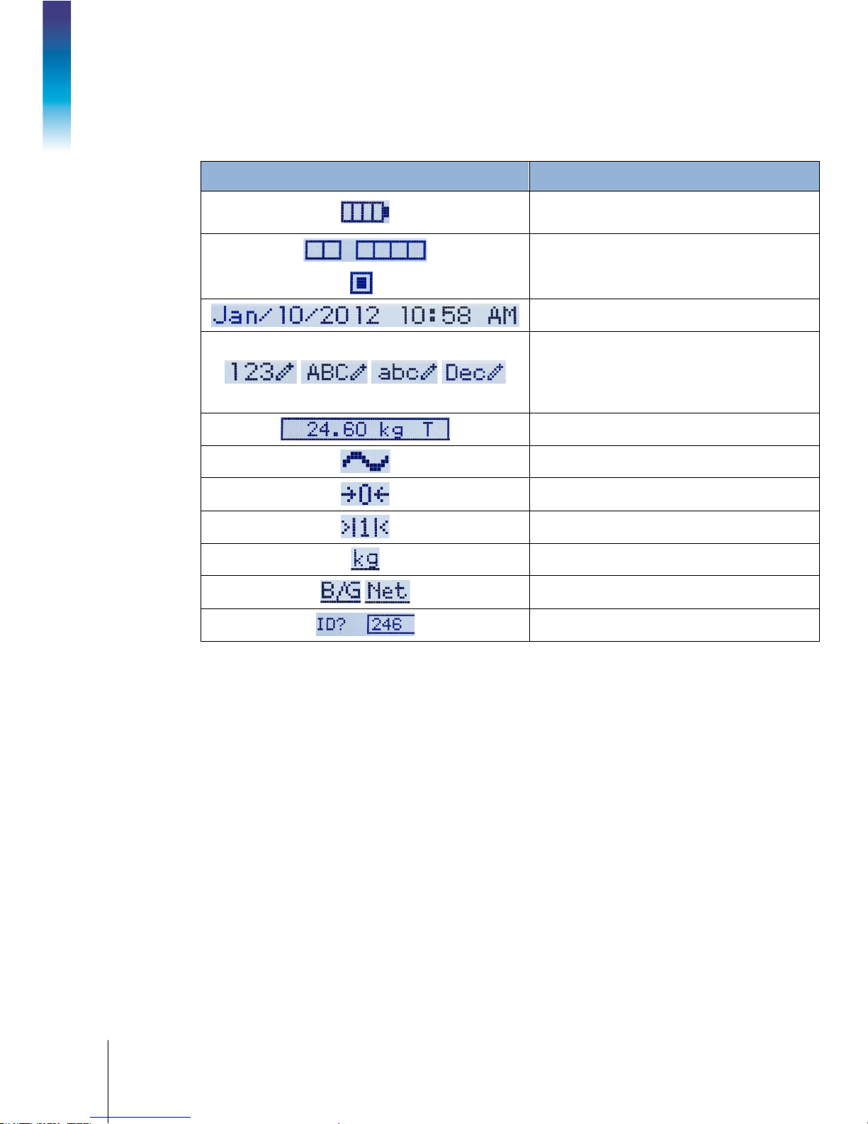
When in the weighing mode, the display is used for indicating the weight value and other types of
information related to the weight. Refer to Figure 2-1.
Figure 2-1: Elements of the Display
2-2
METTLER TOLEDO IND246 and IND246 POWERCELL User's Guide
64084448 | 03 | 10/2017
The symbols that may appear on the display are described in Table 2-1.
Table 2-1: Main Display Symbols
Symbol Explanation
Battery status indicator (battery-powered version
only)
= Input or output active
I/O status* (On and Off)
2 inputs, 4 outputs
Time and date*
Numeric, Upper case alpha, lower case alpha and
Decimal data entry mode.
Decimal mode is available only in the template
string entry screens
Operation: Terminal
Tare type and value indicator
Motion on platform
Center of zero
Weighing range*
Unit (kg, lb, oz, lb-oz, g, ton, t)
Bruto/Gross or Net operating mode
Prompt for ID entry and entry field
* These elements appear if configured to do so in setup.

64084448 | 03 | 10/2017
METTLER TOLEDO IND246 and IND246 POWERCELL User's Guide
2-3
2.2.2. Keypad Operation
SHIFT
ZERO and SPACE
DECIMAL POINT, PERIOD,
1, HYPHEN, COMMA, SLASH, &
The front panel keys are used to operate and configure the IND246.
2.2.2.1. Alphanumeric Keypad
The IND246 permits the entry of both alphabetical and numeric data, using the 12-element keypad
to the right of the display.
2.2.2.1.1. Key Timeout Period
and additional punctuation
characters
Figure 2-2: Alphanumeric Keypad
When using the keys to enter data, after a set amount of time elapses the terminal accepts the
character that is currently displayed, and moves to the next position. Pressing the key without
allowing the Key Timeout period to elapse cycles through the current option for that key. For
instance, when the
The length of this timeout period is measured in tenths of a second, and can be configured in setup
Terminal > Terminal\Device.
at
2.2.2.1.2. SHIFT Key
The SHIFT key is used to determine the type of entry made when a key is pressed. Four entry
modes are available:
Numerical (123)
Upper case alphabetical (
Lower case alphabetical (
Decimal entry (
The current entry mode is indicated at the upper right corner of the display (Figure 2-1, Table 2-1).
2.2.2.1.3. Entering Numeric Data
To enter a number into either the ID (data) field in the main display, or into a field in one of the
setup screens:
4 key is pressed in mode, the display cycles through g, h and i.
ABC)
abc).
Dec) (This mode is available only when entering template strings.)
1. Check that the entry type display shows 123; if it does not, press the SHIFT key until 123
appears.
2. Then simply press the appropriate keys on the key pad – 0 to 9 and period.
2-4
METTLER TOLEDO IND246 and IND246 POWERCELL User's Guide
64084448 | 03 | 10/2017
SHIFT
ABC
8
T
SHIFT
abc
4 4
h
3 3
e
0
SHIFT SHIFT
4 4 4
I
6 6
N
3
D
SHIFT SHIFT
123
2 4 6
246
246
ENTER
Pressing a numeric key followed by TARE enters a manual tare value. Pressing the ID key
shifts focus to the prompt line at the bottom left of the screen, and allows data entry there.
To delete one or more characters, press the CLEAR key.
2.2.2.1.4. Entering Alphanumeric Data
To enter an alphabetic character:
1. Press the SHIFT key to access the character type (lower or upper case)
2. Press the appropriate key until the correct character displays.
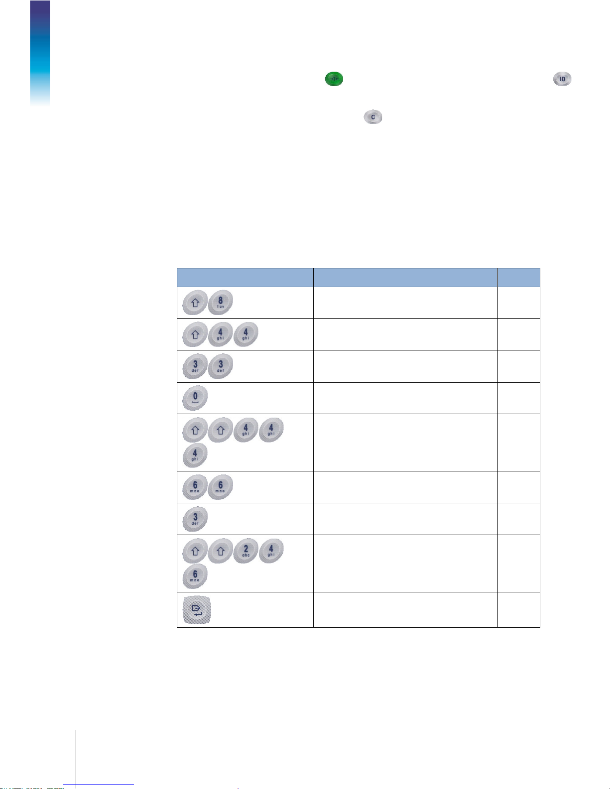
For example, when the display is in its default (numeric, 123) entry mode, the key sequence to
enter
The IND246 (including a space) is shown in Table 2-2.
Table 2-2: Example Data Entry Sequence
Entry Explanation and Notes Result
Operation: Terminal
sets the input mode to
inputs a T
sets the input mode to
inputs an h
inputs an e
enters a space
returns input mode to ABC
inputs an I
inputs an N
inputs a D
sets the input mode to
inputs
confirms data entry

64084448 | 03 | 10/2017
METTLER TOLEDO IND246 and IND246 POWERCELL User's Guide
2-5
2.2.2.2. Function Keys
Scale > Units
Operator Menu
Table 2-3 explains the function of each of the keys during normal operation.
Table 2-3: Keypad Functions – Normal Operation
CLEAR
SWITCH UNITS
ZERO
TARE
MENU
FUNCTION
PRINT/ENTER
ID
When in the net weight mode, press CLEAR to clear the current tare value;
the display will revert to the gross weight value. CLEAR operates regardless
of motion on the scale. Note that once the tare value has been cleared, it
cannot be recalled. The complete tare process as described above must be
performed.
When in alphanumeric entry mode, press CLEAR to backspace and delete
the last character in a string.
Press to toggle between primary and secondary units, as configured in setup
at
.
Used to reset the displayed weight to Zero.
Captures current weight as a tare value, and sets terminal to Net mode.
Changes focus to the ID/data-entry field at the bottom left of the display.
Opens the Operator Menu – refer to the
section starting on
page 2-6.
Toggles between selected application and basic weighing.
Pressing the PRINT key in normal weighing mode will trigger a demand
output (if configured in setup)
During data entry, press ENTER to confirm current selection.
In menus, moves focus to next field label or entry/selection box.
The ZERO and TARE functions will not operate when there is motion on the scale. If one of these
keys is pressed while the scale is in motion, the command will be retained for the programmed
number of seconds while the terminal waits for no-motion. If a no-motion condition is not
detected within the timeout period, the request is cancelled and discarded.
2.2.2.3. Navigation Keys
The navigation keys are used for changing focus between on-screen items, for confirming a
selection, and to initiate a demand output.
ARROW KEYS
PRINT/ENTER
Table 2-4: Navigation Keys
Move focus, or the cursor, in the direction indicated. When the display is in
the menu mode, and the left-most item is selected, the LEFT arrow will return
to the previous screen.
Press the PRINT/ENTER key in the Navigation Keypad to accept the item or
selection in focus and move to the next display.
2-6
METTLER TOLEDO IND246 and IND246 POWERCELL User's Guide
64084448 | 03 | 10/2017
Icon in focus
2.3. Operator Menu
There are a few functions that operators typically perform which are available in a top-level menu
system in the IND246 terminal. These include access to Alibi Memory, setting time and date,
adjusting contrast, viewing and resetting the transaction counter, viewing and clearing totals,
expanding the displayed weight resolution by 10, and recalling information. An explanation of how
to access these functions follows.
2.3.1. Language Selection – F Codes
Depending on the terminal’s language setup (at Terminal > Region > Language), parameter labels
in the operator menu will appear as words (“Hour”)
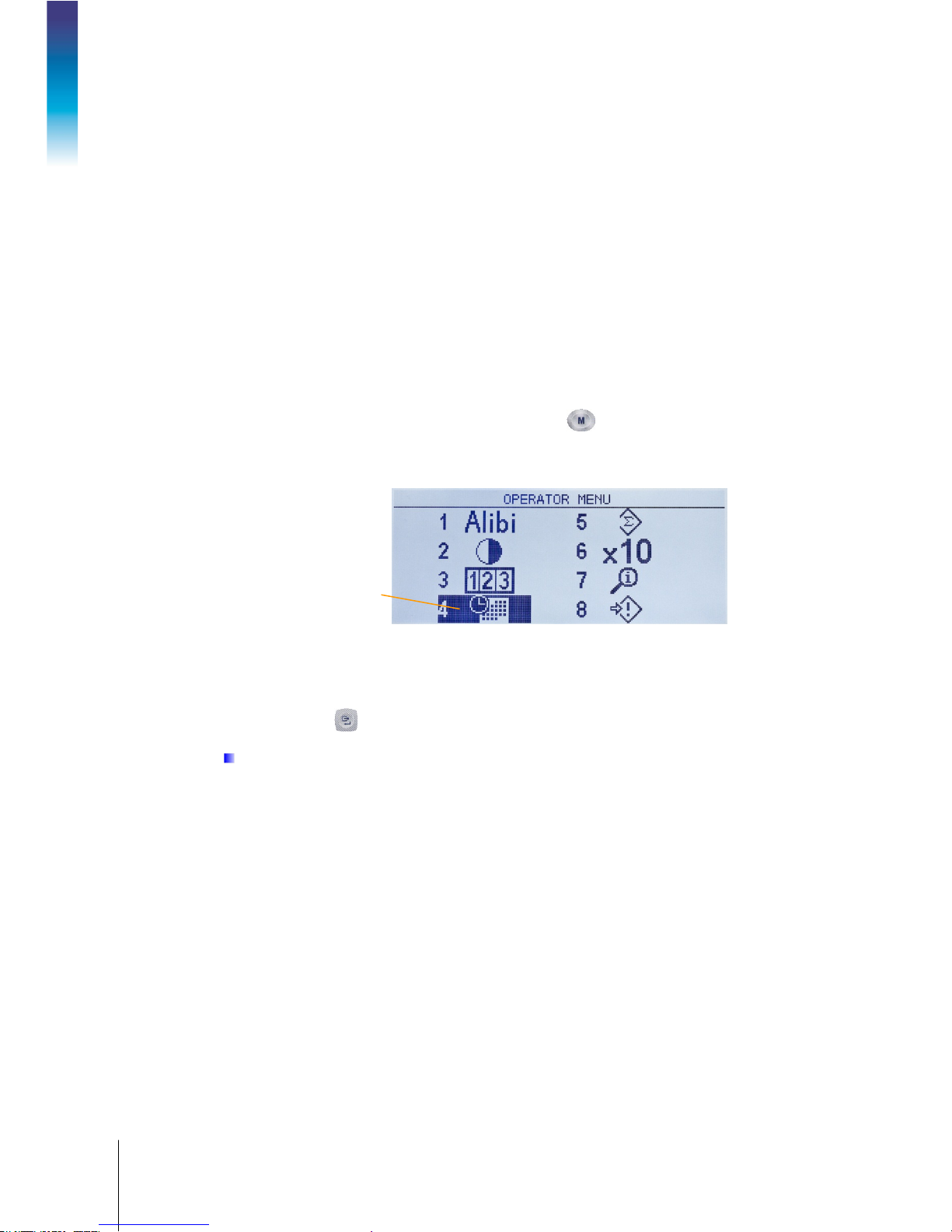
2.3.2. Menu Navigation
To access the operator menu, press the MENU key . The display will change from showing the
normal weigh display to an array of icons (Figure 2-3). The icons included depend on the
Operation: Terminal
terminal’s configuration – for details, refer to Table 2-5.
or as an F-code (“F3.3.2.1”).
Figure 2-3: Operator Menu Display
Items in this menu can be selected directly by pressing the corresponding number on the
alphanumeric keypad, or by using the arrow keys to move focus up, down, left and right and then
pressing ENTER .
When focus is in the left column, as in Figure 2-3 and Figure 2-4, pressing the LEFT arrow key
will exit the
SETUP menu and display the OPERATOR menu.
 Loading...