

Page 1

User's Guide
IND246 and IND246 POWERCELL
Weighing Terminal
Page 2

IND246
IND246
and
POWERCELL Weighing Terminal
Service
METTLER TOLEDO Service
Essential Services for Dependable Performance of Your IND246 and IND246 POWERCELL
Weighing Terminal
Congratulations on choosing the quality and precision of METTLER TOLEDO. Proper use of your
new equipment according to this Manual and regular calibration and maintenance by our factorytrained service team ensures dependable and accurate operation, protecting your investment.
Contact us about a service agreement tailored to your needs and budget. Further information is
available at www.mt.com/service.
There are several important ways to ensure you maximize the performance of your investment:
1.
Register your product: We invite you to register your product at
www.mt.com/productregistration so we can contact you about enhancements, updates and
important notifications concerning your product.
2.
Contact METTLER TOLEDO for service: The value of a measurement is proportional to its
accuracy – an out of specification scale can diminish quality, reduce profits and increase
liability. Timely service from METTLER TOLEDO will ensure accuracy and optimize uptime and
equipment life.
Installation, Configuration, Integration and Training: Our service representatives are factory-
a.
trained, weighing equipment experts. We make certain that your weighing equipment is
ready for production in a cost effective and timely fashion and that personnel are trained for
success.
Initial Calibration Documentation: The installation environment and application
b.
requirements are unique for every industrial scale so performance must be tested and
certified. Our calibration services and certificates document accuracy to ensure production
quality and provide a quality system record of performance.
Periodic Calibration Maintenance: A Calibration Service Agreement provides on-going
c.
confidence in your weighing process and documentation of compliance with requirements.
We offer a variety of service plans that are scheduled to meet your needs and designed to
fit your budget.
GWP® Verification: A risk-based approach for managing weighing equipment allows for
d.
control and improvement of the entire measuring process, which ensures reproducible
product quality and minimizes process costs. GWP (Good Weighing Practice), the sciencebased standard for efficient life-cycle management of weighing equipment, gives clear
answers about how to specify, calibrate and ensure accuracy of weighing equipment,
independent of make or brand.
Page 3
© METTLER TOLEDO 2017
No part of this manual may be reproduced or transmitted in any form or by any
means, electronic or mechanical, including photocopying and recording, for any
purpose without the express written permission of METTLER TOLEDO.
U.S. Government Restricted Rights: This documentation is furnished with
Restricted Rights.
Copyright 2017 METTLER TOLEDO. This documentation contains proprietary
information of METTLER TOLEDO. It may not be copied in whole or in part
without the express written consent of METTLER TOLEDO.
METTLER TOLEDO reserves the right to make refinements or changes to the
product or manual without notice.
COPYRIGHT
METTLER TOLEDO® is a registered trademark of Mettler-Toledo, LLC. All other
brand or product names are trademarks or registered trademarks of their
respective companies.
METTLER TOLEDO RESERVES THE RIGHT TO MAKE REFINEMENTS OR
CHANGES WITHOUT NOTICE.
FCC Notice
This device complies with Part 15 of the FCC Rules and the Radio Interference
Requirements of the Canadian Department of Communications. Operation is
subject to the following conditions: (1) this device may not cause harmful
interference, and (2) this device must accept any interference received, including
interference that may cause undesired operation.
This equipment has been tested and found to comply with the limits for a Class
A digital device, pursuant to Part 15 of FCC Rules. These limits are designed to
provide reasonable protection against harmful interference when the equipment
is operated in a commercial environment. This equipment generates, uses, and
can radiate radio frequency energy and, if not installed and used in accordance
with the instruction manual, may cause harmful interference to radio
communications. Operation of this equipment in a residential area is likely to
cause harmful interference in which case the user will be required to correct the
interference at his or her expense.
Declaration of Conformity is available at
http://glo.mt.com/global/en/home/search/compliance.html/compliance/.
Page 4
Error! Unknown document property name.
Error! Unknown document property name.
In conformance with the European Directive 2002/96/EC on Waste Electrical and Electronic
© METTLER TOLEDO
No part of this manual may be reproduced or transmitted in any form or by any means, electronic or
mechanical, including photocopying and recording, for any purpose without the express written
permission of METTLER TOLEDO.
U.S. Government Restricted Rights: This documentation is furnished with Restricted Rights.
Copyright
METTLER TOLEDO. This documentation
contains proprietary information of METTLER TOLEDO. It may not be copied in whole or in part
without the express written consent of METTLER TOLEDO.
METTLER TOLEDO reserves the right to make refinements or changes to the product or manual
without notice.
COPYRIGHT
METTLER TOLEDO® is a registered trademark of Mettler-Toledo, LLC. All other brand or product
names are trademarks or registered trademarks of their respective companies.
METTLER TOLEDO RESERVES THE RIGHT TO MAKE REFINEMENTS OR CHANGES
WITHOUT NOTICE.
FCC Notice
This device complies with Part 15 of the FCC Rules and the Radio Interference Requirements of the
Canadian Department of Communications. Operation is subject to the following conditions: (1) this
device may not cause harmful interference, and (2) this device must accept any interference
received, including interference that may cause undesired operation.
This equipment has been tested and found to comply with the limits for a Class A digital device,
pursuant to Part 15 of FCC Rules. These limits are designed to provide reasonable protection against
harmful interference when the equipment is operated in a commercial environment. This equipment
generates, uses, and can radiate radio frequency energy and, if not installed and used in
accordance with the instruction manual, may cause harmful interference to radio communications.
Operation of this equipment in a residential area is likely to cause harmful interference in which case
the user will be required to correct the interference at his or her expense.
Declaration of Conformity is available at
http://glo.mt.com/global/en/home/search/compliance.html/compliance/.
Disposal of Electrical and Electronic Equipment
Equipment (WEEE) this device may not be disposed of in domestic waste. This also applies
to countries outside the EU, per their specific requirements.
Please dispose of this product in accordance with local regulations at the collecting point
specified for electrical and electronic equipment.
If you have any questions, please contact the responsible authority or the distributor from
which you purchased this device.
Should this device be passed on to other parties (for private or professional use), the
content of this regulation must also be related.
Thank you for your contribution to environmental protection.
Page 5
Warnings and Cautions
• READ this manual BEFORE operating or servicing this equipment and FOLLOW these
instructions carefully.
• SAVE this manual for future reference.
WARNING
FOR CONTINUED PROTECTION AGAINST SHOCK HAZARD CONNECT THE AC VERSION OF THE
IND246 TERMINAL TO PROPERLY GROUNDED OUTLET ONLY. DO NOT REMOVE THE GROUND
PRONG.
WARNING
DO NOT USE THE IND246 TERMINAL IN AREAS CLASSIFIED AS HAZARDOUS BECAUSE OF
COMBUSTIBLE OR EXPLOSIVE ATMOSPHERES. CONTACT AN AUTHORIZED METTLER TOLEDO
REPRESENTATIVE FOR INFORMATION ABOUT HAZARDOUS AREA APPLICATIONS.
WARNING
WHEN THIS EQUIPMENT IS INCLUDED AS A COMPONENT PART OF A SYSTEM, THE
RESULTING DESIGN MUST BE REVIEWED BY QUALIFIED PERSONNEL WHO ARE FAMILIAR
WITH THE CONSTRUCTION AND OPERATION OF ALL COMPONENTS IN THE SYSTEM AND THE
POTENTIAL HAZARDS INVOLVED. FAILURE TO OBSERVE THIS PRECAUTION COULD RESULT IN
BODILY HARM AND/OR PROPERTY DAMAGE.
CAUTION
THE BATTERY USED IN THIS DEVICE MAY PRESENT A RISK OF FIRE OR CHEMICAL BURN IF
MISTREATED. DO NOT CRUSH, DISASSEMBLE, HEAT ABOVE 60°C OR INCINERATE. REPLACE
BATTERY WITH 72253419 ONLY. USE OF ANOTHER BATTERY MAY PRESENT A RISK OF
BURN, FIRE OR EXPLOSION.
NOTICE
NiMH BATTERIES SLOWLY DISCHARGE WHEN NOT USED (FOR EXAMPLE WHEN STORED FOR FUTURE USE).
BATTERY OPERATED TERMINALS AND SPARE NiMH BATTERY PACKS IN STORAGE MUST BE FULLY CHARGED
EVERY THREE MONTHS TO PREVENT PERMANENT BATTERY DAMAGE.
NOTICE
DO NOT ATTEMPT TO CHARGE THE BATTERY IF THE BATTERY TEMPERATURE IS BELOW 0°C (32°F). CHARGING IS
NOT POSSIBLE AT OR BELOW THIS TEMPERATURE. DO NOT OPERATE THE BATTERY CHARGER OUTSIDE ITS
TEMPERATURE RANGE OF 0°C (32°F) TO 40°C (104°F).
DISPOSE OF USED BATTERY PROMPTLY. KEEP AWAY FROM CHILDREN. DO NOT DISASSEMBLE AND DO NOT
DISPOSE OF IN FIRE.
NOTICE
Page 6

NOTICE
OBSERVE PRECAUTIONS FOR HANDLING ELECTROSTATIC SENSITIVE DEVICES.
Warnings and Cautions
Page 7

64084448 / Rev. 03 / 12/2017
METTLER TOLEDO IND246 and IND246 POWERCELL Weighing Terminal User's Guide 1
Contents
1 Introduction ...................................................................... 1-1
1.1. IND246 Overview ............................................................... 1-1
1.1.1. Standard Features .................................................................................. 1-1
1.1.2. IND246 Terminal Versions ...................................................................... 1-2
1.2. Specifications .................................................................... 1-2
1.3. Battery Performance ........................................................... 1-5
1.4. Use in Hazardous Areas ...................................................... 1-6
1.5. Inspection and Contents Checklist ........................................ 1-6
1.6. Model Identification ............................................................ 1-7
1.7. Physical Dimensions .......................................................... 1-8
1.8. Main PCB .......................................................................... 1-9
1.8.1. SD Memory ........................................................................................... 1-9
1.9. Scale Bases ...................................................................... 1-9
1.9.1. Analog .................................................................................................. 1-9
1.9.2. POWERCELL .......................................................................................... 1-9
1.9.3. PowerDeck .......................................................................................... 1-10
1.10. Options ........................................................................... 1-10
1.10.1. COM2 Serial Port .................................................................................. 1-10
1.10.2. Discrete I/O .......................................................................................... 1-11
1.10.3. USB .................................................................................................... 1-11
1.10.4. Ethernet ............................................................................................... 1-11
1.11. Display and Keyboard ...................................................... 1-12
1.11.1. Display Layout ..................................................................................... 1-12
1.11.2. Front Panel Keys .................................................................................. 1-12
2 Operation: Terminal .......................................................... 2-1
2.1. Overview ........................................................................... 2-1
2.2. Display Elements and Keypad Operation ............................... 2-1
2.2.1. Display Elements ................................................................................... 2-1
2.2.2. Keypad Operation ................................................................................... 2-3
2.3. Operator Menu ................................................................... 2-6
2.3.1. Language Selection – F Codes ................................................................. 2-6
2.3.2. Menu Navigation .................................................................................... 2-6
2.3.3. Alibi Memory ......................................................................................... 2-9
2.3.4. Adjust Contrast ....................................................................................... 2-9
2.3.5. Transaction Counter .............................................................................. 2-10
2.3.6. Totals Memory ..................................................................................... 2-10
2.3.7. Expand x 10 ........................................................................................ 2-10
2.3.8. Information Recall ................................................................................ 2-11
2.3.9. Setup Access ....................................................................................... 2-12
Page 8

2 METTLER TOLEDO IND246 and IND246 POWERCELL Weighing Terminal User's Guide
64084448 / Rev. 03 / 12/2017
2.4. Basic Functionality ........................................................... 2-12
2.4.1. Zero .................................................................................................... 2-12
2.4.2. Tare .................................................................................................... 2-13
2.4.3. Unit Switching ...................................................................................... 2-17
2.4.4. Expand By 10 ...................................................................................... 2-17
2.4.5. Print .................................................................................................... 2-17
2.4.6. Information Recall ................................................................................ 2-18
2.4.7. ID Entry ............................................................................................... 2-18
2.4.8. Time and Date ..................................................................................... 2-19
Contents
2.4.9. Totalization .......................................................................................... 2-19
2.4.10. Alibi Memory ....................................................................................... 2-19
2.5. Applications .................................................................... 2-20
2.5.1. Animal Weighing .................................................................................. 2-20
2.5.2. Checkweighing .................................................................................... 2-20
2.5.3. Counting ............................................................................................. 2-21
2.5.4. Peak Weight ........................................................................................ 2-21
2.5.5. Vehicle Weighing ................................................................................. 2-22
3 Configuration: Terminal ..................................................... 3-1
3.1. Entering Setup Mode ........................................................... 3-1
3.2. Security ............................................................................. 3-1
3.3. Exiting Setup Mode ............................................................. 3-2
3.4. Setup Menu Structure .......................................................... 3-2
3.4.1. Navigation ............................................................................................. 3-2
3.4.2. Setup Page ............................................................................................ 3-2
3.5. Configuration: Overview ...................................................... 3-5
3.6. Configuration: Scale ........................................................... 3-6
3.6.1. Type ..................................................................................................... 3-6
3.6.2. Load Cell ............................................................................................... 3-7
3.6.3. Capacity and Increment ........................................................................ 3-11
3.6.4. Calibration ........................................................................................... 3-13
3.6.5. Zero .................................................................................................... 3-14
3.6.6. Tare .................................................................................................... 3-15
3.6.7. Units ................................................................................................... 3-17
3.6.8. Filter ................................................................................................... 3-17
3.6.9. Stability ............................................................................................... 3-18
3.6.10. Log or Print ......................................................................................... 3-18
3.6.11. Scale Reset .......................................................................................... 3-19
3.7. Configuration: Application ................................................. 3-20
3.7.1. Memory............................................................................................... 3-20
3.7.2. Totalization .......................................................................................... 3-20
3.7.3. Discrete I/O .......................................................................................... 3-21
3.7.4. Function Key ........................................................................................ 3-21
3.7.5. Animal Weighing .................................................................................. 3-22
Page 9

64084448 / Rev. 03 / 12/2017
METTLER TOLEDO IND246 and IND246 POWERCELL Weighing Terminal User's Guide 3
3.7.6. Counting ............................................................................................. 3-23
3.7.7. Checkweighing .................................................................................... 3-24
3.7.8. Peak Weight ........................................................................................ 3-25
3.7.9. Vehicle Weighing ................................................................................. 3-26
3.7.10. Reset .................................................................................................. 3-26
3.8. Configuration: Terminal ..................................................... 3-27
3.8.1. Device ................................................................................................. 3-27
3.8.2. Display ............................................................................................... 3-27
3.8.3. Region ................................................................................................ 3-28
3.8.4. Transaction Counter .............................................................................. 3-30
3.8.5. User .................................................................................................... 3-30
3.8.6. Menu Keys .......................................................................................... 3-30
3.8.7. Reset .................................................................................................. 3-31
3.9. Configuration: Communication ........................................... 3-31
3.9.1. Templates............................................................................................ 3-31
3.9.2. Reports ............................................................................................... 3-33
3.9.3. Connections ........................................................................................ 3-33
3.9.4. Serial .................................................................................................. 3-36
3.9.5. Network............................................................................................... 3-38
3.9.6. Reset .................................................................................................. 3-39
3.10. Configuration: Maintenance ............................................... 3-39
3.10.1. Diagnostics ......................................................................................... 3-39
3.10.2. Scale .................................................................................................. 3-39
3.10.3. Replace Battery .................................................................................... 3-47
3.10.4. Install Software Update .......................................................................... 3-47
3.10.5. Backup to SD ....................................................................................... 3-47
3.10.6. Restore from SD ................................................................................... 3-47
3.10.7. POWERCELL Maintenance ..................................................................... 3-47
3.10.8. Reset All - Factory Default Settings.......................................................... 3-52
3.11. Restoring Factory Default Settings ....................................... 3-52
4 Applications: Configuration and Operation .......................... 4-1
4.1. Introduction ....................................................................... 4-1
4.2. Animal Weighing ................................................................ 4-1
4.2.1. Overview ............................................................................................... 4-1
4.2.2. Operational Features ............................................................................... 4-2
4.2.3. Configuration ......................................................................................... 4-3
4.2.4. Operating Sequence ................................................................................ 4-4
4.2.5. Remote Displays .................................................................................... 4-6
4.2.6. Serial Input Commands ........................................................................... 4-6
4.2.7. Print Formats ......................................................................................... 4-6
4.3. Checkweighing (Over/Under) ............................................... 4-8
4.3.1. Overview ............................................................................................... 4-8
4.3.2. Operational Features ............................................................................... 4-8
4.3.3. Configuration ......................................................................................... 4-9
Page 10

4 METTLER TOLEDO IND246 and IND246 POWERCELL Weighing Terminal User's Guide
64084448 / Rev. 03 / 12/2017
4.3.4. Operating Sequence .............................................................................. 4-14
4.3.5. Print Formats ....................................................................................... 4-18
4.4. Counting ......................................................................... 4-20
4.4.1. Overview ............................................................................................. 4-20
4.4.2. Operational Features ............................................................................. 4-21
4.4.3. Configuration ....................................................................................... 4-21
4.4.4. Operating Sequences ............................................................................ 4-24
4.4.5. Print Formats ....................................................................................... 4-28
4.5. Peak Weight Measurement ................................................ 4-30
Contents
4.5.1. Overview ............................................................................................. 4-30
4.5.2. Operational Features ............................................................................. 4-30
4.5.3. Configuration ....................................................................................... 4-31
4.5.4. Operating Sequences ............................................................................ 4-32
4.5.5. Memory Operation ................................................................................ 4-34
4.5.6. Print Formats ....................................................................................... 4-35
4.6. Vehicle Weighing ............................................................. 4-37
4.6.1. Overview ............................................................................................. 4-37
4.6.2. Operational Features ............................................................................. 4-38
4.6.3. Configuration ....................................................................................... 4-38
4.6.4. Operating Sequences ............................................................................ 4-42
4.6.5. Print Formats ....................................................................................... 4-47
5 Service and Maintenance .................................................. 5-1
5.1. Cleaning and Maintenance .................................................. 5-1
5.2. Service .............................................................................. 5-1
5.3. Battery Operation ................................................................ 5-2
5.3.1. Specifications ........................................................................................ 5-2
5.3.2. Battery Status Icon .................................................................................. 5-3
5.3.3. Accessing the Battery Pack ...................................................................... 5-3
5.3.4. Charging the Battery Pack ....................................................................... 5-5
5.3.5. Disposing of a Depleted Battery Pack ....................................................... 5-7
5.4. Troubleshooting ................................................................. 5-7
5.4.1. Blank Display ........................................................................................ 5-7
5.4.2. Power Test............................................................................................. 5-8
5.4.3. Problem Diagnosis ................................................................................. 5-8
5.4.4. Error Codes and Error Messages .............................................................. 5-9
5.4.5. Internal Diagnostics .............................................................................. 5-11
5.5. Replacing BRAM Battery .................................................... 5-14
5.6. System Backup and Restore .............................................. 5-15
5.6.1. Files, Media and Data ........................................................................... 5-15
5.6.2. Backup to SD Memory Card ................................................................... 5-16
5.6.3. Restore from SD Memory Card ............................................................... 5-16
5.7. Master Reset .................................................................... 5-17
Page 11

64084448 / Rev. 03 / 12/2017
METTLER TOLEDO IND246 and IND246 POWERCELL Weighing Terminal User's Guide 5
5.8. Upgrading Firmware ......................................................... 5-18
5.9. Board and Display Replacement ........................................ 5-18
5.9.1. Option Board Removal .......................................................................... 5-19
5.9.2. Main Board Removal ............................................................................ 5-19
5.9.3. Display Module Removal ...................................................................... 5-21
5.9.4. Display Module Installation ................................................................... 5-22
5.9.5. Main PCB Installation ........................................................................... 5-22
5.9.6. Option PCB Installation ......................................................................... 5-22
5.9.7. Final Steps........................................................................................... 5-23
A Default Templates ............................................................. A-1
A.1. Basic Functionality ............................................................. A-1
A.2. Vehicle Application ............................................................. A-2
A.3. Checkweighing Application .................................................. A-3
A.4. Peak Weight Application ..................................................... A-4
A.5. Animal Weighing Application ............................................... A-5
A.6. Counting Application ........................................................... A-5
B Parameter Values ............................................................. B-1
B.1. Scale Block, IND246 Analog ............................................... B-1
B.2. Scale Block, IND246 POWERCELL ....................................... B-5
B.3. Application Block ............................................................... B-8
B.4. Terminal Block ................................................................. B-15
B.5. Communications Block ..................................................... B-18
B.6. Maintenance Block, IND246 Analog ................................... B-24
B.7. Maintenance Block, IND246 POWERCELL ........................... B-26
C Alibi Memory .................................................................... C-1
C.1. Viewing Alibi Memory Records ............................................. C-1
C.2. Printing Alibi Memory Records ............................................. C-2
C.3. Alibi Memory Print Formats .................................................. C-3
C.3.1. Narrow Format, * Record Separator .......................................................... C-3
C.3.2. Wide Format, = Record Separator ............................................................ C-3
D Communications ............................................................... D-1
D.1. Serial Interface Parameters .................................................. D-1
D.2. Demand Output Mode ......................................................... D-2
D.2.1. Output Templates ................................................................................... D-2
D.3. Continuous Output Mode ..................................................... D-3
D.3.1. Standard Continuous Output .................................................................... D-3
D.3.2. Continuous Output in Animal Weighing ..................................................... D-5
D.3.3. Continuous – Extended Output ................................................................. D-5
Page 12

6 METTLER TOLEDO IND246 and IND246 POWERCELL Weighing Terminal User's Guide
64084448 / Rev. 03 / 12/2017
D.3.4. Multi-Continuous Out .............................................................................. D-8
D.4. Scoreboard Displays ......................................................... D-11
D.4.1. Continuous Output ................................................................................ D-12
D.4.2. Continuous Multi-1 Output ..................................................................... D-12
D.5. CTPZ .............................................................................. D-13
D.6. Standard Interface Command Set (SICS) Protocol ................. D-14
D.6.1. Version Number of the MT-SICS.............................................................. D-14
D.6.2. Command Formats ............................................................................... D-14
D.6.3. Response Formats ................................................................................ D-15
Contents
D.6.4. Tips for the Programmer ........................................................................ D-16
D.6.5. Commands and Responses MT-SICS Level 0 .......................................... D-16
D.6.6. Commands and Responses MT-SICS Level 1 .......................................... D-20
D.7. Reports ........................................................................... D-23
D.7.1. Alibi Memory ....................................................................................... D-23
D.7.2. Totals Report ....................................................................................... D-24
D.8. Variable Access ................................................................ D-24
D.8.1. Connection .......................................................................................... D-24
D.8.2. Commands ......................................................................................... D-24
D.8.3. Variable List ......................................................................................... D-26
E GEO Codes ....................................................................... E-1
E.1. Original Site Calibration ....................................................... E-1
E.2. New Site GEO Code Adjustment ............................................ E-1
Page 13

64084448 | 03 | 12/2017
METTLER TOLEDO IND246 and IND246 POWERCELL User's Guide
1-1
This chapter covers
1 Introduction
The IND246 and IND246 POWERCELL industrial scale terminals provide a
• Overview
• Specifications
• Use in Hazardous Areas
• Safe Disposal Requirement
• Inspection and Contents
Checklist
• Model Identification
• Physical Dimensions
• Main PCB
• Scale Bases
• Options
• Display and Keyboard
Standard applications include basic weighing, animal weighing, check weighing, counting, peak
weight measurement and vehicle weighing. Whether communicating weight data to a PC or
providing a serial output of data to a printer, the IND246 terminal offers solutions for a wide range
of applications.
compact yet flexible solution to a variety of weighing needs. Available as either AC
powered for stationary applications or battery-powered for portable analog load cell
applications, this terminal is at home in virtually any industrial environment.
Innovative use of Secure Data (SD) Memory technology expands the memory
available for data storage when required.
Unless stated otherwise, IND246 refers to both the analog and POWERCELL
versions.
Both 2mv/V and 3mv/V analog load cells are supported without the need for
any configuration change. The POWERCELL model supports the advanced
capabilities of POWERCELL PDX and GDD load cells, featuring sophisticated selfdiagnostics. The PowerDeck model for POWERCELL supports a connector for quick
home run cable termination, faster calibration and automatic addressing. The
IND246 delivers precision measurement data from grams to tons in a single, cost
effective package.
1.1. IND246 Overview
1.1.1. Standard Features
• Rugged stainless steel enclosure
• Supports one analog load cell platform with up to four (battery version), ten (AC version)
350Ω load cells; or one scale platform with up to 12 POWERCELL PDX load cells; or up to 3
PowerDeck scale platforms, each with 4 SLB615D load cells; or up to 12 SLC611D LCWM
load cells
• Large transflective graphic LCD display with backlight for vivid readability in all light
conditions
• One electrically isolated serial port (COM1) for asynchronous, bidirectional communication
• Powered by either 85–264 V AC or internal battery pack (selected by model)
• Support for the following option boards:
Choice of one serial/DIO option:
Page 14

1-2
METTLER TOLEDO IND246 and IND246 POWERCELL User's Guide
64084448 | 03 | 12/2017
Enclosure Type
Dimensions (w ×
h × d)
Shipping Weight
o COM2 Serial Interface
o COM2 and Discrete I/O interface (analog version only)
o USB Serial Interface
o USB and Discrete I/O interface (analog version only)
Optional network interface:
o Ethernet TCP/IP
• Front panel key access to basic weighing functions – zero, tare, clear, unit switching and
print
• Alpha numeric keypad for simple, quick entry of tare and identification information
Introduction
• Selectable primary unit of measure including grams, kilograms, pounds, tons, metric tons
• Selectable second unit of measure including grams, kilograms, pounds, ounces, tons and
metric tons
• Backup and restore of configuration and calibration settings, using SD memory device or
• PC-based File Transfer Tool (included) exchanges application files and tables with the
®
SL PC tool (included)
InSite
IND246 terminal
• Automatic shutoff and backlight timeout features to help conserve energy on the battery
powered version
1.1.2. IND246 Terminal Versions
The terminal is available in the following four versions:
• IND246 Harsh enclosure, AC power
• IND246 Harsh enclosure, Battery power
• IND246 POWERCELL, AC power
• IND246 POWERCELL for SL_61xD, AC power
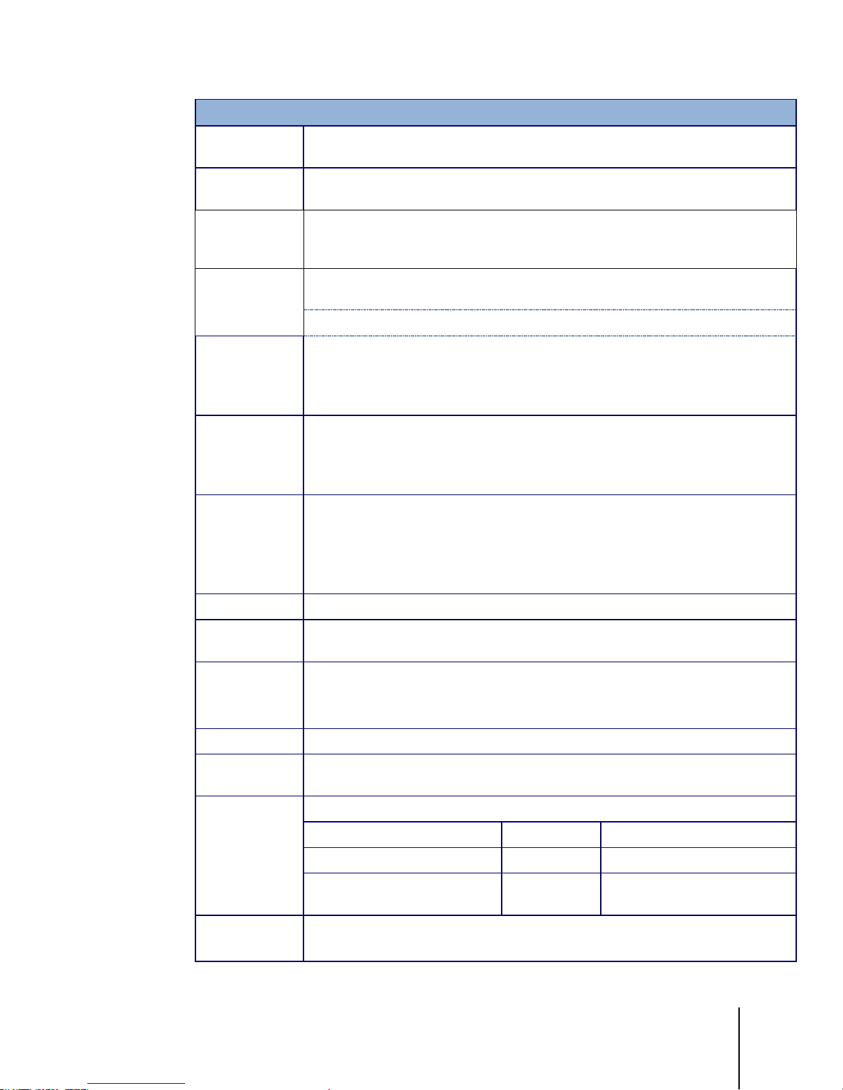
1.2. Specifications
The IND246 terminal conforms to the specifications listed in Table 1-1.
Table 1-1: Terminal Specifications
Stainless steel, configurable as desk top or wall mount enclosure
230 mm x 146 mm x 165 mm (9 in. x 5.75 in. x 6.5 in.)
AC Version: 3.4 kg (7.5 lb)
Battery Version: 3.9 kg (8.5 lb)
POWERCELL Version: 3.6 kg (7.9 lb)
IND246 Specifications
Page 15
64084448 | 03 | 12/2017
METTLER TOLEDO IND246 and IND246 POWERCELL User's Guide
1-3
IND246 Specifications
Environmental
Protection
Operating
Environment
Hazardous Areas
Power
Power
Consumption
Power
Consumption
Display
Weight Display
Scale Types
Number of Cells
Number of Scales
Analog
Update Rate
POWERCELL
Update Rate
Update Rates (Hz)
Update Rate, Type
Synchronized Continuous Weight
Load Cell
Excitation Voltage
IP66 (comparable to Type 4x)
The terminal can be operated at temperatures ranging from −10° to 40° C (14° to
104° F) at 10% to 95% relative humidity, non-condensing.
The IND246 terminal cannot be operated in areas classified as Hazardous because of
combustible or explosive atmospheres in those areas. Contact an authorized METTLER
TOLEDO representative for information about hazardous area applications.
AC version: Operates at 85–264 VAC, 49–61 Hz and includes a power cord configured
for the country of use.
Battery version: Operates from internal NiMH battery pack
Refer to Table 1-2 for details of the AC version. Values shown are with internal COM2/DIO
option and Ethernet option installed and load cell input loaded with 8 x 350Ω load cells.
Refer to Table 1-3 for Refer to Table 1-4 for details of the battery life for the battery
powered version.
Refer to Table 1-2 for the AC version; Table 1-3 for IND246 POWERCELL; and Table 1-4
for the battery version.
Values shown in Table 1-2 are for an IND246 terminal with the internal COM2/DIO and
Ethernet options installed, and input from 8 x 350Ω load cells.
Backlit 240 x 96 dot graphic LCD including weight display, weight units, gross/net
indication and graphic symbols for motion and center of zero, SmartTrac, operator
prompts and data entry display. Update rate of 12 updates per second.
Basic weight mode: 27 mm (1.1 in) high weight display
Application mode: 20 mm (0.8 in) high weight display
Maximum displayed resolution of 50,000 divisions.
Analog load cells (AC or battery models), POWERCELL PDX, GDD, SLC611D or
SLD615D load cells (POWERCELL model),
AC Version: From one to ten 350-ohm load cells (2 or 3 mV/V)
Battery Version: From one to four 350-ohm load cells (2 or 3 mV/V)
POWERCELL Version: Up to 12 POWERCELL PDX, GDD, SLC611D or SLB615D load cells
One
Internal analog: 366 MHz
Vehicle, 12 load cells
Load Cell Network 25
Output
USB, COM1,
COM2, Ethernet
17 - 25
AC Version: 10 VDC
Battery Version : 5 V DC
Page 16
1-4
METTLER TOLEDO IND246 and IND246 POWERCELL User's Guide
64084448 | 03 | 12/2017
Minimum
Sensitivity
Keypad
Communications
Approvals,
Analog Version
Approvals,
POWERCELL
Version
IND246 Specifications
0.1 microvolt per increment
25 keys; polyester overlay (PET) with polycarbonate display lens
Serial Interfaces
Standard: One isolated serial port (COM1) RS-232 (analog only); RS-232/RS-422-
RS-485 (POWERCELL only), 300 to 115,200 baud
Optional isolated serial port: (COM2) RS-232/485, 300 to 115,200 baud
Optional USB port: serial port bridge, 300 to 115,200 baud
Introduction
Ethernet Interface
Optional Ethernet port: 10/100 TCP/IP port
Protocol
Serial Inputs: ASCII commands for CTPZ (Clear, Tare, Print, Zero), SICS (most level 0
and level 1 commands)
Serial Outputs: Continuous, Extended continuous, Demand (limited formats), Reports,
SICS (most level 0 and level 1 commands) or Variable Access
Weights and Measures
USA: NTEP Class III/IIIL - 10,000d; Cert. #11-040
Canada: Class III - 10,000d; Class IIIHD - 20,000d; AM-5819
Europe: Class III 6000e, Class IIII 1000e; TC7918, T8030
OIML: Class III 6000e, Class IIII 1000e; R76/2006-NL1-15.49R1
Product Safety
UL, cUL, CE
Weights and Measures
USA: : NTEP Class III/IIIL - 10,000d; Cert. #11-040
Canada: Class III - 10,000d; Class IIIHD - 20,000d; AM-5819
Europe: Class III 6000e, Class IIII 1000e; TC7918, T8426
OIML: Class III 6000e, Class IIII 1000e; R76/2006-NL1-15.49R1
Product Safety
UL, cUL, CE
Table 1-2: IND246 Power Consumption (AC Source)
Input Voltage I (mA) P (W)
85V/50 Hz 167 7.9
110 V/50 Hz 133 7.7
240 V/50 Hz 64 7.9
264 V/50 Hz 59 7.9
85 V/60 Hz 163 7.9
110 V/60 Hz 128 7.7
240 V/60 Hz 62 7.9
Page 17
64084448 | 03 | 12/2017
METTLER TOLEDO IND246 and IND246 POWERCELL User's Guide
1-5
Input Voltage I (mA) P (W)
264 V/60 Hz 58 8.0
Values shown are with internal COM2/DIO option and Ethernet option installed and load cell input
loaded with 8 x 350Ω load cells.
Table 1-3: Power Consumption for POWERCELL Version
Input Voltage I(mA) P(W)
85V/50Hz 112 5.7
110V/50Hz 94 6
240V/50Hz 73 8.4
264V/50Hz 72 8.7
85V/60Hz 108 5.8
110V/60Hz 92 6
240V/60Hz 73 8.3
264V/60Hz 73 8.6
Table 1-4: IND246 Average Battery Life, Analog Version
Continuous Operation Load
1- 350Ω cell, no options 21.5 hrs 49 hrs
1 – 350Ω cell, COM2/DIO option 12.5 hrs 19 hrs
4 – 350Ω cells, no options 17. 5 hrs 32 hrs
4 – 350Ω cells, COM2/DIO option 11 hrs 15.5 hrs
1.3. Battery Performance
NiMH BATTERIES SLOWLY DISCHARGE WHEN NOT USED (FOR EXAMPLE WHEN STORED FOR FUTURE USE).
BATTERY OPERATED TERMINALS AND SPARE NiMH BATTERY PACKS IN STORAGE MUST BE FULLY CHARGED EVERY
THREE MONTHS TO PREVENT PERMANENT BATTERY DAMAGE.
Battery Life
w/Backlight
NOTICE
Battery Life w/o
Backlight
Page 18
1-6
METTLER TOLEDO IND246 and IND246 POWERCELL User's Guide
64084448 | 03 | 12/2017
• IND246 Terminal
• Safety Instructions
1.4. Use in Hazardous Areas
WARNING
DO NOT USE THE IND246 TERMINAL IN AREAS CLASSIFIED AS HAZARDOUS BECAUSE OF
COMBUSTIBLE OR EXPLOSIVE ATMOSPHERES. CONTACT AN AUTHORIZED METTLER TOLEDO
REPRESENTATIVE FOR INFORMATION ABOUT HAZARDOUS AREA APPLICATIONS.
1.5. Inspection and Contents Checklist
Introduction
Verify the contents and inspect the package immediately upon delivery. If the shipping container is
damaged, check for internal damage and file a freight claim with the carrier if necessary. If the
container is not damaged, remove the terminal from its protective package, noting how it was
packed, and inspect each component for damage.
If shipping the terminal is required, it is best to use the original shipping container. The terminal
must be packed correctly to ensure its safe transportation.
The package should include:
• Battery Pack (battery version only)
• Mounting brackets (2; analog version only)
• Resource CD (includes all manuals)
• Bag of miscellaneous parts
Page 19
64084448 | 03 | 12/2017
METTLER TOLEDO IND246 and IND246 POWERCELL User's Guide
1-7
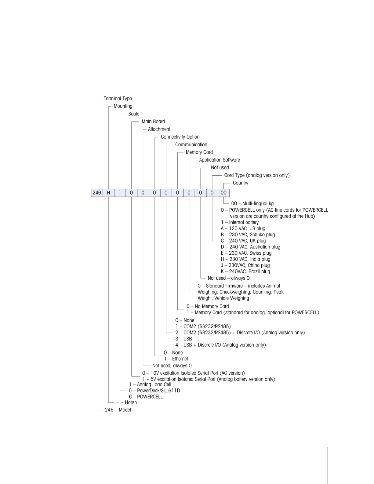
1.6. Model Identification
The IND246 and IND246 POWERCELL model number, factory number and serial number are
located on the data plate of the terminal. Refer to Figure 1-1 to verify the configuration of the
IND246 terminal when it left the METTLER TOLEDO factory.
Figure 1-1: IND246 Configuration Chart
Page 20
1-8
METTLER TOLEDO IND246 and IND246 POWERCELL User's Guide
64084448 | 03 | 12/2017
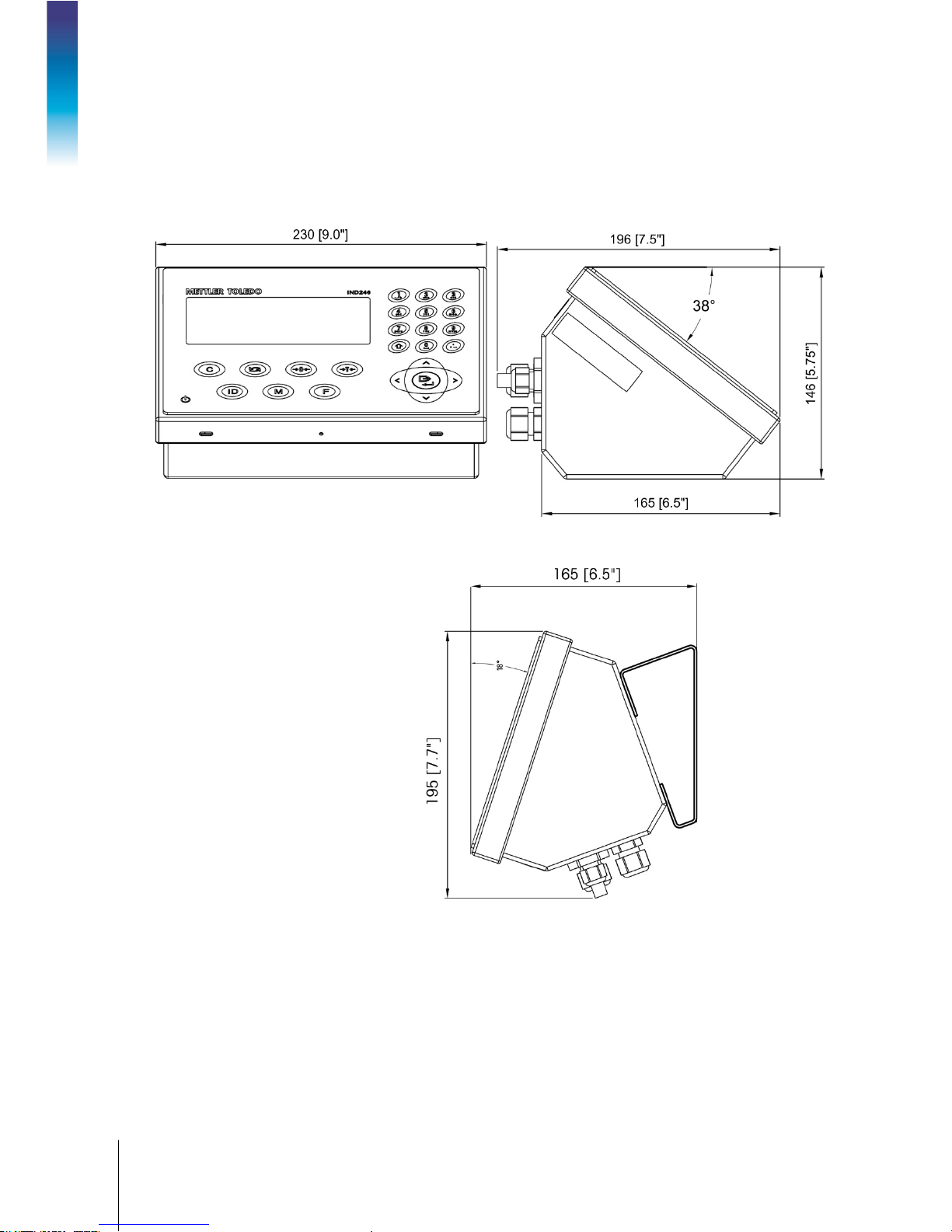
1.7. Physical Dimensions
The physical dimensions of the IND246 enclosure are shown in Figure 1-2 and Figure 1-3 in mm
and [inches].
Introduction
Figure 1-2: IND246 Enclosure Dimensions
Figure 1-3: IND246 Dimensions with Brackets
Page 21

64084448 | 03 | 12/2017
METTLER TOLEDO IND246 and IND246 POWERCELL User's Guide
1-9
1.8. Main PCB
The IND246 terminal’s main printed circuit board (PCB) provides the analog load cell scale
interface, as well as the COM1 RS-232 serial port. The IND246 POWERCELL main board provides
the load cell interface and a standard COM1 RS-232/RS-422/RS-485 isolated serial port.
The main board also contains the power input connection (for either AC supply or battery,
depending on the model), display interface, keypad interface and six-position DIP switch.
An SD memory card socket is mounted to the PCB to support the optional SD memory and bus
connectors are included for the option boards.
1.8.1. SD Memory
An SD Memory card is included as a standard feature of the analog version of the IND246, and is
available as an option for the POWERCELL version. The card provides a medium on which to store
files such as Alibi memory, transaction records in the vehicle application, IDs in the counting
application and target weights in the checkweighing application.
The SD memory can be used to extract and save the configuration and calibration settings of the
terminal. These can then be restored to the terminal or loaded to a different terminal.
1.9. Scale Bases
1.9.1. Analog
The standard IND246 terminal supports analog scale bases and provides either 10 volts (AC
version) or 5 volts (battery version) of excitation to drive analog load cells. Up to four (battery
version) or ten (AC version) 350Ω load cells can be powered by the terminal.
A six wire load cell connection is provided with sense lines to help maintain accuracy as the load
cell cable resistance changes with temperature variations.
1.9.2. POWERCELL
The IND246 POWERCELL terminal supports scale bases that use POWERCELL PDX, GDD,
SLC611D or SLB615D load cells. Up to 12 load cells can be configured in a single scale platform.
The load cell network provides monitoring and logging of a variety of factors that can affect system
integrity, including weighing errors, overloads and network health. The specific characteristics differ
by type of load cell.
Page 22

1-10
METTLER TOLEDO IND246 and IND246 POWERCELL User's Guide
64084448 | 03 | 12/2017
1.9.3. PowerDeck
The IND246 POWERCELL supports PowerDeckTM weighing platforms. These provide calibration
without weights for fast installation and visual guidance for leveling the floor platform.
Introduction
Figure 1-4: IND246 POWERCELL with PowerDeck Platform
1.10. Options
The following options are available for all versions of the IND246:
• COM2 Serial Port
One RS-232/485 isolated serial COM port
COM2 and DIO (relay output)
•
One RS-232/485 isolated serial COM port
Internal, discrete I/O (2 inputs and 4 outputs; supported in analog version only)
─ Inputs are optically isolated solid state and switch selectable as either active or passive
─ Output relays provide one normally open contact per relay
•
USB Port
One USB 2.0 compliant port, hardware bridge. Acts as virtual (UCP) COM port
USB and DIO (relay output)
•
One USB 2.0 compliant port, hardware bridge. Acts as virtual (UCP) COM port
Internal, discrete I/O (2 inputs and 4 outputs; supported in analog version only)
─ Inputs are optically isolated solid state and switch selectable as either active or passive
─ Output relays provide one normally open contact per relay
•
Ethernet Port
One 10/100 Ethernet port with automatic link polarity detection and correction. Supports TCP/IP socket
connection. Does not support FTP
1.10.1. COM2 Serial Port
This optional port provides RS-232 and RS-485 communication at rates from 300 to 115.2k baud.
The port is bidirectional and can be configured for various functions such as demand output,
continuous output, extended continuous output, SICS host communications or ASCII command
input (C, T, P, Z).
Page 23

64084448 | 03 | 12/2017
METTLER TOLEDO IND246 and IND246 POWERCELL User's Guide
1-11
The COM2 port is galvanically isolated for both RS-232 and RS-485, to provide surge voltage
protection.
The RS-485 connection can be used as an RS-422 transmit only when sending continuous output
to a scoreboard or remote display.
1.10.2. Discrete I/O
The Discrete I/O option is supported only in the analog version of the IND246.
The discrete I/O interface option provides dry-contact relay outputs. The relay contacts will switch up
to 30 volts DC or 250 volts AC at 1A.
The inputs are switch selectable as either active (for simple pushbutton control) or passive (for
connection to devices that supply their own power for the inputs).
1.10.3. USB
The USB port provided is a hardware bridge acting as a virtual COM port, and is used for
conversion of serial data. The port is bidirectional and can be configured for various functions such
as demand output, continuous output, extended continuous output, SICS host communications or
ASCII command input (C, T, P, Z).
1.10.4. Ethernet
The IND246 Ethernet option provides an RJ45 jack for connection to an Ethernet network or host
device. A TCP socket connection can be made to port 1701 to transfer files or to exchange data
with a PC. This port can also operate as a print client to send data to a network printer.
Page 24
1-12
METTLER TOLEDO IND246 and IND246 POWERCELL User's Guide
64084448 | 03 | 12/2017
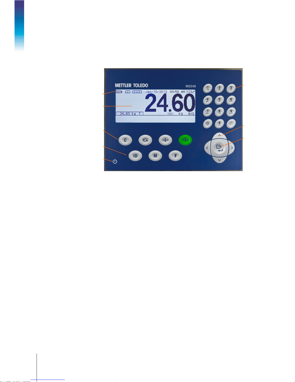
System line
1.11. Display and Keyboard
The IND246 terminal uses a graphic, transflective type Liquid Crystal Display (LCD) with a white
LED backlight. The front panel including the display and keypad is shown in Figure 1-4.
Alphanumeric
keypad
Introduction
Scale Function keys
1.11.1. Display Layout
At the top of the display, a single system line displays terminal status and operator error displays
and messages. Time and date and the status of the Digital I/O can be displayed in this area, when
so configured in setup.
Below the system line is the weight display. During normal, basic weighing operation, the IND246
terminal display shows the Gross or Net weight in the larger 28.5mm (1.1 in.) size. When one of
the applications is running, the weight is shown in 20mm (0.8 in.) high characters. Below the
weight display is a single line to display the weight units, the weight legend, the center of zero icon,
weight range and motion icon. Tare values also appear on this line, to the left of the display.
LCD display
Navigation
keys
Print/Enter key
Operational
keys
ON/OFF key
Figure 1-5: IND246 Front Panel Layout
At the bottom of the normal basic weighing display is a line used for data entry. For display
operation during setup, refer to Chapter 3,
1.11.2. Front Panel Keys
The IND246 terminal provides a total of 25 keys as operator interfaces. The ON/OFF key, four scale
function keys and three operational keys are positioned under the display while the alpha-numeric
keys are positioned to the right of the display. The print/enter key and navigation keys are located at
the bottom right of the display. These keys are used to enter the setup menu, to navigate and select
setup elements, and to enter values in setup as described in Chapter 3,
Configuration.
Configuration.
Page 25

64084448 | 03 | 10/2017
METTLER TOLEDO IND246 and IND246 POWERCELL User's Guide
2-1
This chapter covers
2 Operation: Terminal
2.1. Overview
This chapter provides information about the basic functionality of the IND246 terminal,
• Overview
• Basic Functionality
• Display Operation
• Keypad Operation
• Operator Menu
• Applications
2.2. Display Elements and Keypad Operation
Refer to Figure 1-4 for an over view of the layout of the front panel of the IND246.
2.2.1. Display Elements
including display operation, keypad functions and menu navigation.
Operation of the terminal varies depending on which functions are enabled, and on the
configuration of parameters in setup. Configuration is described in Chapter 3,
Terminal.
Configuration:
When in the weighing mode, the display is used for indicating the weight value and other types of
information related to the weight. Refer to Figure 2-1.
Figure 2-1: Elements of the Display
Page 26
2-2
METTLER TOLEDO IND246 and IND246 POWERCELL User's Guide
64084448 | 03 | 10/2017
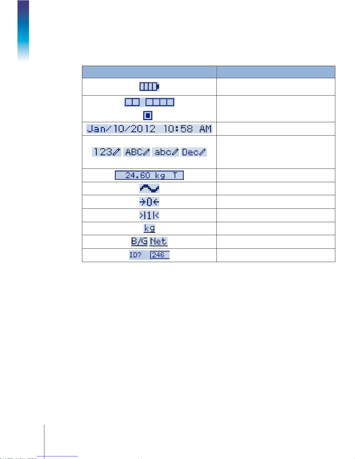
The symbols that may appear on the display are described in Table 2-1.
Table 2-1: Main Display Symbols
Symbol Explanation
Battery status indicator (battery-powered version
only)
= Input or output active
I/O status* (On and Off)
2 inputs, 4 outputs
Time and date*
Numeric, Upper case alpha, lower case alpha and
Decimal data entry mode.
Decimal mode is available only in the template
string entry screens
Operation: Terminal
Tare type and value indicator
Motion on platform
Center of zero
Weighing range*
Unit (kg, lb, oz, lb-oz, g, ton, t)
Bruto/Gross or Net operating mode
Prompt for ID entry and entry field
* These elements appear if configured to do so in setup.
Page 27
64084448 | 03 | 10/2017
METTLER TOLEDO IND246 and IND246 POWERCELL User's Guide
2-3
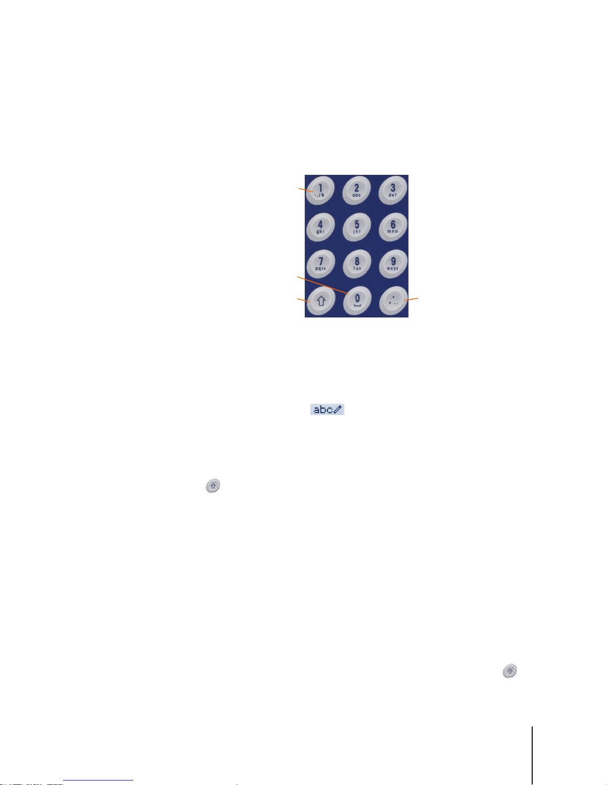
2.2.2. Keypad Operation
SHIFT
ZERO and SPACE
DECIMAL POINT, PERIOD,
1, HYPHEN, COMMA, SLASH, &
The front panel keys are used to operate and configure the IND246.
2.2.2.1. Alphanumeric Keypad
The IND246 permits the entry of both alphabetical and numeric data, using the 12-element keypad
to the right of the display.
2.2.2.1.1. Key Timeout Period
and additional punctuation
characters
Figure 2-2: Alphanumeric Keypad
When using the keys to enter data, after a set amount of time elapses the terminal accepts the
character that is currently displayed, and moves to the next position. Pressing the key without
allowing the Key Timeout period to elapse cycles through the current option for that key. For
instance, when the
The length of this timeout period is measured in tenths of a second, and can be configured in setup
Terminal > Terminal\Device.
at
2.2.2.1.2. SHIFT Key
The SHIFT key is used to determine the type of entry made when a key is pressed. Four entry
modes are available:
Numerical (123)
Upper case alphabetical (
Lower case alphabetical (
Decimal entry (
The current entry mode is indicated at the upper right corner of the display (Figure 2-1, Table 2-1).
2.2.2.1.3. Entering Numeric Data
To enter a number into either the ID (data) field in the main display, or into a field in one of the
setup screens:
4 key is pressed in mode, the display cycles through g, h and i.
ABC)
abc).
Dec) (This mode is available only when entering template strings.)
1. Check that the entry type display shows 123; if it does not, press the SHIFT key until 123
appears.
2. Then simply press the appropriate keys on the key pad – 0 to 9 and period.
Page 28
2-4
METTLER TOLEDO IND246 and IND246 POWERCELL User's Guide
64084448 | 03 | 10/2017
SHIFT
ABC
8
T
SHIFT
abc
4 4
h
3 3
e
0
SHIFT SHIFT
4 4 4
I
6 6
N
3
D
SHIFT SHIFT
123
2 4 6
246
246
ENTER
Pressing a numeric key followed by TARE enters a manual tare value. Pressing the ID key
shifts focus to the prompt line at the bottom left of the screen, and allows data entry there.
To delete one or more characters, press the CLEAR key.
2.2.2.1.4. Entering Alphanumeric Data
To enter an alphabetic character:
1. Press the SHIFT key to access the character type (lower or upper case)
2. Press the appropriate key until the correct character displays.
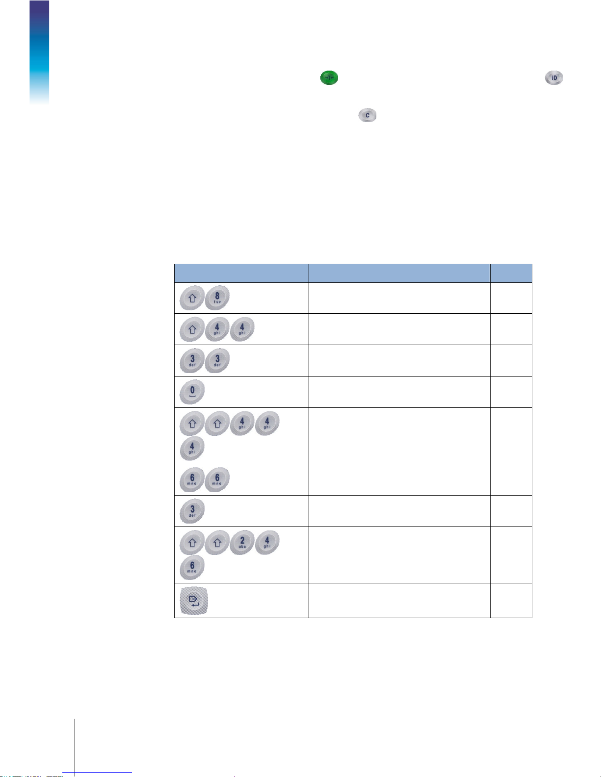
For example, when the display is in its default (numeric, 123) entry mode, the key sequence to
enter
The IND246 (including a space) is shown in Table 2-2.
Table 2-2: Example Data Entry Sequence
Entry Explanation and Notes Result
Operation: Terminal
sets the input mode to
inputs a T
sets the input mode to
inputs an h
inputs an e
enters a space
returns input mode to ABC
inputs an I
inputs an N
inputs a D
sets the input mode to
inputs
confirms data entry
Page 29

64084448 | 03 | 10/2017
METTLER TOLEDO IND246 and IND246 POWERCELL User's Guide
2-5
2.2.2.2. Function Keys
Scale > Units
Operator Menu
Table 2-3 explains the function of each of the keys during normal operation.
Table 2-3: Keypad Functions – Normal Operation
CLEAR
SWITCH UNITS
ZERO
TARE
MENU
FUNCTION
PRINT/ENTER
ID
When in the net weight mode, press CLEAR to clear the current tare value;
the display will revert to the gross weight value. CLEAR operates regardless
of motion on the scale. Note that once the tare value has been cleared, it
cannot be recalled. The complete tare process as described above must be
performed.
When in alphanumeric entry mode, press CLEAR to backspace and delete
the last character in a string.
Press to toggle between primary and secondary units, as configured in setup
at
.
Used to reset the displayed weight to Zero.
Captures current weight as a tare value, and sets terminal to Net mode.
Changes focus to the ID/data-entry field at the bottom left of the display.
Opens the Operator Menu – refer to the
section starting on
page 2-6.
Toggles between selected application and basic weighing.
Pressing the PRINT key in normal weighing mode will trigger a demand
output (if configured in setup)
During data entry, press ENTER to confirm current selection.
In menus, moves focus to next field label or entry/selection box.
The ZERO and TARE functions will not operate when there is motion on the scale. If one of these
keys is pressed while the scale is in motion, the command will be retained for the programmed
number of seconds while the terminal waits for no-motion. If a no-motion condition is not
detected within the timeout period, the request is cancelled and discarded.
2.2.2.3. Navigation Keys
The navigation keys are used for changing focus between on-screen items, for confirming a
selection, and to initiate a demand output.
ARROW KEYS
PRINT/ENTER
Table 2-4: Navigation Keys
Move focus, or the cursor, in the direction indicated. When the display is in
the menu mode, and the left-most item is selected, the LEFT arrow will return
to the previous screen.
Press the PRINT/ENTER key in the Navigation Keypad to accept the item or
selection in focus and move to the next display.
Page 30
2-6
METTLER TOLEDO IND246 and IND246 POWERCELL User's Guide
64084448 | 03 | 10/2017
Icon in focus
2.3. Operator Menu
There are a few functions that operators typically perform which are available in a top-level menu
system in the IND246 terminal. These include access to Alibi Memory, setting time and date,
adjusting contrast, viewing and resetting the transaction counter, viewing and clearing totals,
expanding the displayed weight resolution by 10, and recalling information. An explanation of how
to access these functions follows.
2.3.1. Language Selection – F Codes
Depending on the terminal’s language setup (at Terminal > Region > Language), parameter labels
in the operator menu will appear as words (“Hour”)
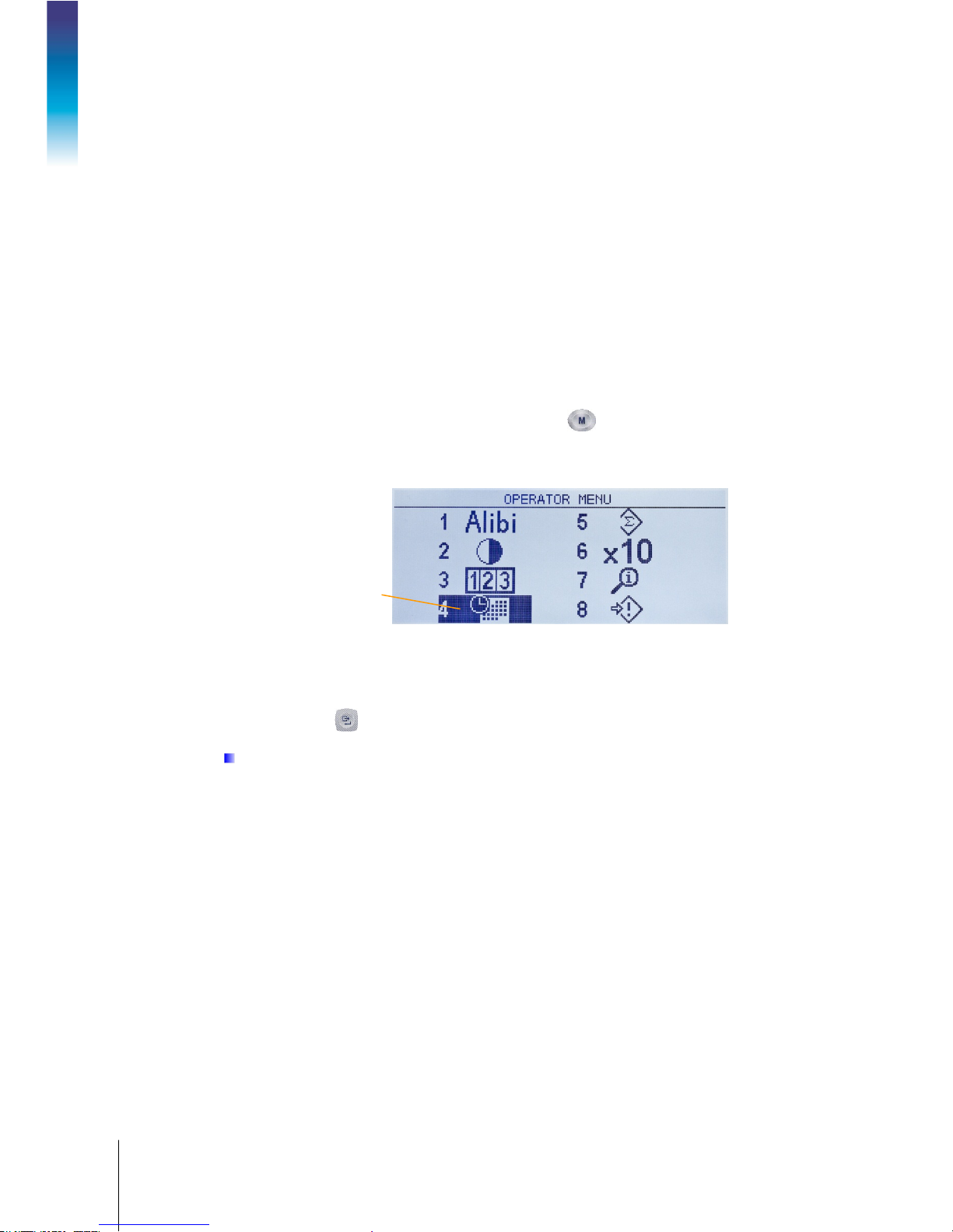
2.3.2. Menu Navigation
To access the operator menu, press the MENU key . The display will change from showing the
normal weigh display to an array of icons (Figure 2-3). The icons included depend on the
Operation: Terminal
terminal’s configuration – for details, refer to Table 2-5.
or as an F-code (“F3.3.2.1”).
Figure 2-3: Operator Menu Display
Items in this menu can be selected directly by pressing the corresponding number on the
alphanumeric keypad, or by using the arrow keys to move focus up, down, left and right and then
pressing ENTER .
When focus is in the left column, as in Figure 2-3 and Figure 2-4, pressing the LEFT arrow key
will exit the
SETUP menu and display the OPERATOR menu.
Page 31

64084448 | 03 | 10/2017
METTLER TOLEDO IND246 and IND246 POWERCELL User's Guide
2-7
2.3.2.1. Accessing Operator Screens
For instance, from the screen shown in Figure 2-3, pressing ENTER or pressing 4 displays the Time
& Date setup screen.
Here, items may be selected by number or by moving focus and pressing ENTER.
Figure 2-4: Set Time & Date
Note that the header line reflects the currently displayed screen, and the input mode icon is also
displayed at upper right.
In Figure 2-4, a field label (Hour) is in focus. In Figure 2-5, the numeric entry field for the Hour
value is selected. Use the number pad keys to modify the value. When the correct number is
displayed, press ENTER to confirm the selection and move to the next (
When all the time and date values are correctly set, press the LEFT arrow key to return to the
Operator Menu (Figure 2-3).
2.3.2.2. Operator Menu Items
Depending upon programming in the terminal and whether one of the Applications is enabled in
setup, the icons displayed will include a selection of those shown in Table 2-5. The
Recall and Setup icons will always appear last in the list. The other icons can be added or removed
from the operator menu by configuring the menu keys display in setup at
Figure 2-5: Time & Date Setup, Hour Field in Focus
Minutes) field label.
Information
Terminal > Menu Keys.
Page 32

2-8
METTLER TOLEDO IND246 and IND246 POWERCELL User's Guide
64084448 | 03 | 10/2017
Standard
Alibi Memory
ALIBI SEARCH
Adjust Contrast
ADJUST CONTRAST
Transaction Counter
TRANSACTION COUNTER
Time and Date
SET TIME & DATE
Totals Memory
TOTALS
Expand x10
Information Recall
RECALL INFO
Setup
Terminal >
Users
Counting Application
Switch Sampling
Mode
ID Memory
ID Table
Reports
ID Table
Over/Under Application
Target
ACTIVE VALUES
Set Target
QUICK SET TARGET
Target Memory
TARGET TABLE
Reports
TARGET TABLE
Vehicle Application
Temporary ID
Temporary ID Table
Permanent ID
Permanent ID Table
Table 2-5: Operator Menu Icons
Icon Function Description
Displays the
Displays the
Displays the
Displays the
Displays the
on whether Subtotals are enabled or disabled.
screen.
screen.
screen.
screen.
screen. The contents of this screen vary depending
Changes the main display to add an additional digit to the displayed
weight. The appearance of the display will differ, depending on whether
the terminal is in approved or non-approved mode.
Operation: Terminal
Displays the
software version, last calibration date, etc., are displayed.
Enters the setup menu. Depending on the settings made at
, it may be necessary to enter a valid user name and password to
access the setup menus.
Switches sampling mode between piece sampling and APW entry.
Displays a view of the
screen, where the terminal’s serial number,
, from which an ID can be selected for use.
Displays the
Displays
for printing . The table can also be cleared .
screen, where target, tolerances and description
can be edited.
Displays
screen, where target, tolerances and
description can be entered using live scale weight.
Displays
Displays the
.
cleared
Displays a view of the
Displays a view of the
, from which a target can be selected for use.
for printing. Totals in the table can also be
.
.
Page 33

64084448 | 03 | 10/2017
METTLER TOLEDO IND246 and IND246 POWERCELL User's Guide
2-9
Icon Function Description
Reports
Vehicle ID Table
Temporary ID Table
Peak Weigh Application
Reports
PEAK WEIGHT MEMORY
Search Field 1
Transaction Counter*
Data Comparison
equal to (=)*
Data
2.3.3. Alibi Memory
The Alibi Memory key opens the ALIBI SEARCH screen. Here, the contents of Alibi memory can be
viewed and printed. The results can be filtered using comparisons with one or two search fields,
and printed. The elements of this search screen are summarized in Table 2-6. Default values are
indicated in bold.
Displays a printable
depending on which mode is active.
Displays the
printed or cleared
.
page. Values on the page can be
Table 2-6: Elements of the Alibi Search Screen
Field Function / Options
, Date (2010-11-07), Gross Weight, Net
Weight, Tare Weight, Time (15:51:40)
Less than (<), less than or equal to (<=),
or equal to (=>), greater than (>), not equal to (≠)
Alphanumeric entry field for value to be compared. Default is * (all).
or
,
,greater than
Once the search has been defined and executed, the ALIBI SEARCH VIEW screen opens, displaying
the results.
Press the UP and DOWN arrow keys to scroll through the entries.
Press the PRINT key to output the search results to a connected printer or the LEFT arrow to exit
the view.
To print a report, the communications port must have the assignment Reports.
2.3.4. Adjust Contrast
Displays the ADJUST CONTRAST screen. The display contrast can be set for best visibility. Press the
UP arrow to make the screen darker, and the DOWN arrows to make the screen lighter, and exit by
pressing the LEFT arrow.
Figure 2-6: Alibi Search View
Page 34

2-10
METTLER TOLEDO IND246 and IND246 POWERCELL User's Guide
64084448 | 03 | 10/2017
Non-Approved Mode
123.45
123.456
Figure 2-7: Contrast Adjustment Screen
2.3.5. Transaction Counter
Opens the TRANSACTION COUNTER screen, in which a value can be entered in the Next Transaction
screen. Once the value is entered, press ENTER to confirm it, and the LEFT arrow key to exit the
screen.
Operation: Terminal
2.3.6. Totals Memory
Depending on how the terminal is configured in setup at Application > Totalization, this screen
displays the Grand Total of number of transactions and total weight, or both Grand Total and
Subtotal of transactions with accumulated weight for each.
2.3.7. Expand x 10
This icon toggles the weight display between standard and expanded mode. When this icon is
selected and ENTER pressed, the weight display appears. The appearance of the expanded display
differs, depending on whether or not the terminal is approved:
I
Figure 2-8: Transaction Counter Screen
Figure 2-9: Totals Memory
An extra digit of resolution is added to the main weight display (e.g.
becomes
The PRINT function prints weights in the expanded format.
) and the x10 indicator appears in place of the range symbol.
Page 35

64084448 | 03 | 10/2017
METTLER TOLEDO IND246 and IND246 POWERCELL User's Guide
2-11
Approved Mode
123.45
123.456
2.3.8. Information Recall
Model
Serial No.
Platform Model
Platform Serial Number
Option 1
Option 2
Firmware
The information recall function is always available in the operator menu. In the Operator Menu,
select the Information Recall icon and press ENTER, to recall specific information about the
terminal. The RECALL screen displays, with two screens of information available. Move between the
two screens by pressing the UP and DOWN arrow keys. Figure 2-10 shows an example of the two
pages of information, and Table 2-7 lists the elements in the sequence in which they appear. Some
items may not appear, depending on the configuration of the terminal. Press the LEFT arrow key to
exit the RECALL screen.
An extra digit of resolution is added to the main weight display, in a smaller size
(e.g.
The PRINT function is disabled.
becomes
). The range symbols operate normally.
Figure 2-10: Information Recall Screens
Table 2-7: Information Recall Menu Items
Item Value/Explanation
The model number of the terminal is shown.
Serial number of the terminal as entered in the setup mode.
The model number of the platform.
Serial number of the platform.
Shows installed hardware options, if any.
Shows the firmware revision number (2 lines).
Page 36

2-12
METTLER TOLEDO IND246 and IND246 POWERCELL User's Guide
64084448 | 03 | 10/2017
Service
Approved
Certificate #
Calibrated
IP Address
• Zero
• Clearing Tare
• Information Recall
Tare
Print
Target
Item Value/Explanation
2.3.9. Setup Access
The last icon displayed in the OPERATOR menu accesses the SETUP menu, from which all the
Operation: Terminal
terminal’s programming parameters can be viewed and modified. The settings and options
available in setup are described in detail in Chapter 3,
It is not intended that operators enter the setup mode. After a weighing system is installed and is
operational, it should not be necessary for an operator to access setup.
Note that a security password can be enabled in setup. When a password is set, it must be entered
in order to access setup. This protects the setup parameters from inadvertent changes.
Shows date of most recent calibration.
A telephone number used to contact METTLER TOLEDO authorized
service.
or
No
Yes
Indicates whether the terminal has been programmed as Approved
for use in legal for trade applications.
Displays approval certificate number. An approval region must be
selected to enable the display of the certificate number.
IP address assigned to the terminal. Shown only when the Ethernet
option is installed.
Configuration: Terminal.
2.4. Basic Functionality
This section provides information about IND246 basic functionality. Functions addressed in this
section include:
•
Refer to Chapter 3, Configuration: Terminal, for further information about programming all the
functionality described in this section.
2.4.1. Zero
The Zero function is used to set or reset the initial zero reference point of the terminal. There are
three types of zero setting modes:
• Automatic Zero Maintenance
• Power Up Zero
• Pushbutton Zero
When the scale platform or weighbridge is empty, the terminal should indicate zero. The gross zero
reference is recorded during calibration. If pushbutton zero is enabled in configuration and the
weight is within the zero range pressing ZERO will capture a new gross zero reference point.
•
•
Page 37

64084448 | 03 | 10/2017
METTLER TOLEDO IND246 and IND246 POWERCELL User's Guide
2-13
2.4.1.1. Automatic Zero Maintenance
• Pushbutton Tare
• Net Sign Correction
• Keyboard (Preset) Tare
• Automatic Tare
Tare Clear
Automatic Zero Maintenance (AZM) enables the IND246 to compensate for the build up of small
amounts of weight and track itself back to the center of zero. Within the AZM operating range
(selectable from 0.5, 1, 3 or 10 divisions), when the terminal is in a no motion condition, it makes
small adjustments to the current zero reading to drive the weight reading toward the true center-ofzero. When the weight is outside of the programmed AZM range, this feature is not functional.
2.4.1.2. Power Up Zero
Power-Up Zero enables the IND246 terminal to capture a new zero reference point after power is
applied. If there is motion during a power-up zero capture function, the terminal will continue to
check for a no-motion condition until zero is captured.
Power-up zero can be disabled or enabled, and a range above and below calibrated zero can be
configured. The range is programmable from 0% to 100% of capacity and can include a positive
range and also a range below calibrated zero.
2.4.1.3. Pushbutton Zero
The pushbutton (semi-automatic) zero function can be accomplished by pressing the ZERO key
, by programming a discrete input or by issuing a serial command.
The range for all types of semi-automatic zero is selectable (Disabled, 2% or 20%) plus or minus
from the calibrated zero point.
Remote initiation of the semi-automatic Zero command is possible via a discrete input, or an ASCII
‘Z’ command sent serially (CPTZ and SICS interface modes).
2.4.2. Tare
Tare is the weight of an empty container. A tare value subtracts from the gross weight
measurement, providing the computation of the net weight (material without the container). The tare
function can also be used to track the net amount of material being added to or removed from a
vessel or container. In this second case, the weight of the material in the container is included with
the tare weight of the container and the display then reflects the net amount being added to or
removed from the vessel.
Tare operations in the IND246 include:
•
2.4.2.1. Pushbutton Tare
Pushbutton tare can be configured in setup as enabled or disabled. When disabled, pressing the
TARE key
— Manual Clear
— Auto Clear
has no effect.
Page 38

2-14
METTLER TOLEDO IND246 and IND246 POWERCELL User's Guide
64084448 | 03 | 10/2017
If pushbutton tare is enabled, pressing the pushbutton TARE key initiates a semi-automatic
tare. The IND246 will attempt to perform a tare process. If the process is successful, the display
changes to a zero net weight indication and the previous weight on the scale is stored as the tare
value. The net mode will be indicated on the display.
Several conditions could inhibit the pushbutton tare function:
Motion – Pushbutton tare cannot be taken when the scale is in motion. If motion is detected
when a pushbutton tare command is received, the IND246 will wait for a programmed
amount of time (the default value is 3 seconds) for a no-motion condition. If a stable (no
motion) weight condition occurs before the timeout expires, the pushbutton tare command
is executed.
If there is still motion at the end of the timeout, the command is aborted.
Pushbutton Tare Disabled – If pushbutton tare is configured as disabled, the TARE scale
function key will not initiate a semi-automatic tare.
Operation: Terminal
2.4.2.2. Keyboard Tare
A keyboard (preset) tare is a numeric tare that is entered manually through the numeric keypad or
received serially from a peripheral. The preset tare value cannot exceed the capacity of the scale.
Data entered is interpreted to have the same units as the current displayed value. Motion does not
affect the entry of preset tare values.
Keyboard tare can be configured in setup as enabled or disabled. When disabled, the numeric
keypad and the TARE scale function key
To enter a preset tare value manually, use the numeric keypad to enter the tare value (the data
entered will display in the weight legend if keyboard tare is enabled in setup at
Types) and press the TARE scale function key .
If configured in setup, remote equipment can enter a preset tare value using a serial command
If the preset tare is successful, the display changes to a net weight indication.
Several conditions could inhibit the preset tare function:
•
•
Negative Gross Weight – Any pushbutton tare attempted when the gross weight is at or below
zero is ignored. Ensure that the gross weight is above zero.
cannot be used to obtain a tare.
Scale > Tare >
Keyboard Tare Disabled – If keyboard tare is configured in setup as disabled, the numeric
keypad and the TARE scale function key
Over-Capacity or Under-Zero Conditions – Preset tare is not allowed when the weight display
indicates over capacity or under zero conditions. Any preset tare attempted when the scale is
over capacity is ignored and a “Tare Failed–Over Cap” error displays. Any preset tare attempted
when the weight display indicates an under zero condition is ignored and a “Tare Failed–Too
Small” error displays.
cannot be used to obtain a tare.
A preset tare can be entered in free format. If the entered value does not match the displayed weight
decimal point location or display interval, the entered tare value is rounded to the nearest display
interval and the decimal point adjusted to match the gross weight. The rounding method is that 0.5
Page 39

64084448 | 03 | 10/2017
METTLER TOLEDO IND246 and IND246 POWERCELL User's Guide
2-15
or more of a display interval (d) is increased to the next display interval and 0.49 or less of a
display interval is decreased to the next lower display interval.
When entering a preset tare value less than 1.0, the operator can enter the data without the leading
zero (left of the decimal point), but all subsequent display, storage, or printing of this value will
include the leading zero. For example, a preset tare entry of .05 will display as 0.05.
If a preset tare has already been established and another preset tare is entered, the second preset
tare replaces the previous value (it does not add to the previous value). The replacement tare can
be larger or smaller than the original tare value.
2.4.2.3. Net Sign Correction
Net sign correction enables the terminal to be used for both shipping (inbound empty) and
receiving (inbound loaded) operations. Net sign correction can be either disabled or enabled on the
IND246.
If net sign correction is disabled in setup, the stored weight value in the tare register is assumed to
be a tare regardless of the gross weight present on the scale at the time of the final transaction. Net
values can therefore be negative if the weight on the scale is less than the tare value.
If net sign correction is enabled, the terminal will switch the gross weight and tare weight fields
when necessary, so that the larger weight is the gross weight, the smaller weight is the tare weight,
with the difference always a positive net weight. Net sign correction affects the display and printed
data.
An example of weight values with and without net sign correction is shown in Table 2-8. In this
example, the tare register value is 53 kg and the live weight on the scale is 16 kg.
2.4.2.4. Automatic Tare
The IND246 can be configured so that tare is automatically taken (auto tare) after the weight on the
scale exceeds a programmed tare threshold weight. Auto tare can be configured in setup as
enabled or disabled. When auto tare is enabled, the display changes to a zero net weight indication
after the weight exceeds the threshold value. The previous weight on the scale is stored in the Alibi
Table as the tare value. Auto tare operations involve:
Tare Threshold Weight – When weight on the scale platform exceeds the tare threshold value,
•
the terminal automatically tares.
Reset Threshold Weight – The reset threshold weight must be less than the tare threshold
•
weight. When the weight on the scale platform falls below the reset threshold value, such as
when a load has been removed, the terminal automatically resets the auto tare trigger.
Table 2-8: Weight Values With and Without Net Sign Correction
Net Sign Correction
Printed and Displayed Disabled Enabled
Gross 16 kg 53 kg
Tare 53 kg 16 kg
Net
−37 kg
37 kg
Page 40

2-16
METTLER TOLEDO IND246 and IND246 POWERCELL User's Guide
64084448 | 03 | 10/2017
• Motion Check – A motion check is provided to control the re-arming of the auto tare function. If
disabled, the auto tare trigger will be reset as soon as the weight falls below the reset value. If
enabled, the weight must settle to no-motion below the reset threshold before the next auto tare
can be initiated.
Several conditions could inhibit the auto tare function:
Motion – Auto tare cannot be taken when the scale is in motion. If motion is detected after the
•
weight on the scale exceeds a preset tare threshold weight, the IND246 will wait for a nomotion condition. If a stable (no motion) weight condition occurs within three seconds, the
auto tare command is executed.
Auto Tare Disabled – Auto tare can be configured in setup as enabled or disabled.
•
2.4.2.5. Clearing Tare
Tare values can be cleared manually or automatically.
2.4.2.5.1. Manual Clear
Operation: Terminal
Manually clear tare values by pressing the CLEAR key on the numeric keypad when the
IND246 is in the net mode and has completed the weighing operation. Motion on the scale will not
impact a manual clear.
If configured in setup, pressing the ZERO scale function key will first clear the tare, then issue a
zero command (see Chapter 3,
2.4.2.5.2. Auto Clear
The IND246 can be configured to clear tare automatically when the weight returns to a value below
a programmable threshold, or when a print command is issued. Once the tare is cleared, the
display returns to the gross weighing mode.
Auto clear is disabled or enabled in setup. If auto clear is enabled the following parameters,
configured in setup, affect the auto clear operation:
Clear Threshold Weight – The clear threshold weight is the gross weight value below which the
•
IND246 will automatically clear a tare after settling to a value above this threshold value.
Motion Check – A motion check is provided to control the automatic clearing of tare. If the
•
motion check is disabled, the tare value is cleared as soon as the weight drops below the
threshold weight (auto clear threshold), regardless of the motion status.
• If the motion check is enabled, after meeting the requirements for weight value above and then
below the threshold weight (auto clear threshold), the IND246 waits for a no-motion condition
before automatically clearing the tare.
Clear After Print – If enabled, tare is automatically cleared and the scale returned to the gross
•
mode after data has been transmitted by pressing the ENTER/PRINT key or from a remote
source.
Configuration: Terminal, the Scale section, Auto Clear).
Refer to the Scale, Auto Clear section of Chapter 3,
about configuring auto clear.
Configuration: Terminal, for further information
Page 41

64084448 | 03 | 10/2017
METTLER TOLEDO IND246 and IND246 POWERCELL User's Guide
2-17
2.4.3. Unit Switching
In order to support locations and applications that utilize multiple measurement units, the IND246
supports unit switching. The SWITCH UNITS key enables switching between primary units (the
main unit of measure) and alternate units.
When the SWITCH UNITS key is pressed, the display changes from the primary unit to the
second unit. When this softkey is pressed again, the display returns to the primary unit. Each
subsequent time the SWITCH UNITS key is pressed the IND246 continues to switch the unit.
When units are switched, the units value changes to the correspondingly selected units, and the
conversion of the display value occurs. The display division changes to an equivalent weight value
in the switched unit (for example, from 0.02 lb to 0.01 kg) and the decimal location switches to
accommodate the conversion.
When switching units, the capacity of the converted units is dictated by the original number of
divisions established in the capacity and increments area of setup. In some situations, this may
reduce the capacity of the terminal when converting to second unit.
2.4.4. Expand By 10
The Expand by 10 icon appears in the OPERATOR menu (Figure 2-3), if so configured. It used to
increase the selected weight display resolution by one additional digit. For example, a weight
display of 40.96 could increase by one additional digit to display as 40.958. The Expand By Ten
mode is indicated on the display by x10, which displays below the weight display. When Expand
by Ten is selected again, the display reverts to the normal display of weight.
If programmed as approved with the metrology switch (SW1-1) ON, the Expand by Ten mode is
displayed for five seconds then automatically returns to normal resolution. Printing is disabled
when the weight is expanded and the terminal is programmed as approved.
2.4.5. Print
The print function (demand print) can be initiated by pressing the ENTER/PRINT key or by
automatic print settings. Demand printing of data may also be initiated as part of a particular
sequence of operation or special application software.
2.4.5.1. Print Interlock
Print Interlock is designed to enforce a single print output per transaction. Print Interlock can be
disabled or enabled. If enabled, the print command is ignored until the measured gross weight
exceeds the print interlock threshold. A print command initiated before the measured gross weight
exceeds the print interlock threshold returns a
line.
After the first print command is executed, subsequent print commands are ignored until the gross
weight indication falls below the print interlock reset threshold. If a print command is blocked by
print Interlock, a
Command failed – scale not ready error in the system
Command failed – scale not ready message appears in the system line.
Page 42

2-18
METTLER TOLEDO IND246 and IND246 POWERCELL User's Guide
64084448 | 03 | 10/2017
2.4.5.2. Automatic Print
Automatic initiation of a demand print occurs after the gross weight exceeds the minimum threshold
and there is no motion on the scale. After initiation, the gross weight must return below the reset
threshold before a subsequent automatic print can occur.
Automatic print may be disabled or enabled. Automatic print can be triggered and reset by weight
exceeding thresholds or by weight deviation from a previously stable reading.
2.4.6. Information Recall
A limited number of data fields are made available for easy recall on the terminal display. These
fields include data such as model, serial number, identification fields, hardware and software
configuration, a service contact phone number and whether the terminal has been set up as
approved for legal for trade operation.
All this data is accessible under the
Operation: Terminal
2.4.7. ID Entry
The ID function is used for two different purposes, depending on whether the terminal is in basic
weighing mode or in one of the application modes.
• In basic weighing mode, a single ID field is available for transaction identification purposes,
and the ID value will be shown at the bottom left of the display. The ID may also be included as
a print field in any of the print templates.
• When the terminal is running one of the applications, the ID key may access records from
an application table.
The basic weighing transactional ID value can be entered using one of two methods, described
below.
2.4.7.1. Pressing the ID key first
Press the ID key . An "ID?" prompt will appear at the bottom of the display, with an entry box to
its right.
Using the alphanumeric keypad, enter the desired ID value and then press ENTER. The ID value will
be shown at the bottom left of the display and will be available for printing.
Information Recall icon in the OPERATOR menu.
To clear the ID field, press the ID key and when the previous ID value is displayed in focus in the
entry box, press the CLEAR key .
2.4.7.2. Pressing the ID key last
Begin to enter the desired ID value using the alpha-numeric keypad. A “Data:” prompt will appear at
the bottom of the display, with an entry box to its right. As keys are pressed, the entered data will be
displayed inside the entry box.
When the complete ID has been entered, press the ID key to terminate the entry. The ID value
will be shown at the bottom left of the display and will be available for printing.
Page 43

64084448 | 03 | 10/2017
METTLER TOLEDO IND246 and IND246 POWERCELL User's Guide
2-19
To clear the ID field, press the ID key and when the previous ID value is displayed in focus in the
entry box, press the CLEAR key .
2.4.8. Time and Date
Select the TIME & DATE menu item in the Terminal > Region menu and press ENTER to display the
Set Time & Date screen (Figure 2-4). When the time is set, seconds are set to 0.
Depending on the terminal’s time and date format settings, the following values can be entered.
Time and date formats, including date field separators, are configured in setup at
Region > Format Time & Date.
Unless otherwise noted, all values are numeric entries:
Hour, AM/PM (if 12-hour time selected)
Minute
Day
Month (selected from a list)
Year
Although the format for the time and date can be selected according to local preferences (in Setup
Terminal > Region > Format Time & Date), the use of a timestamp in log files is not selectable.
at
Timestamp formats are always fixed as:
Terminal >
Time: HH:MM:SS stored in 24 hour format (for example, 10:01:22 PM becomes the fixed format
time 22:01:22)
Date: YYYY/MM/DD (for example, July 23, 2005 becomes the fixed format date 2005/07/23)
2.4.9. Totalization
Knowing how many weighing transactions were performed and how much material was processed
during a particular period of time is useful information for many weighing applications.
The IND246 terminal provides both grand total (GT) and subtotal (ST) registers and counters.
Counters
have a limit of 1,500,000 and registers will accumulate up to 11 digits of weight,
including any digits to the right of the decimal point. For example, a scale programmed for 500 x
0.1 kg will accumulate weight values up to 9999999999.9 (11 total digits). If either of these
limits is exceeded, an error message will display and the totals must be reset before additional
weights or counts will be added.
2.4.10. Alibi Memory
The Alibi Memory stores transaction data that can be retrieved in order to verify transaction
information.
Information stored in the Alibi Memory includes:
• Transaction counter value
• Date and time of transaction
• Gross, net, and tare weights including units of measure
Page 44

2-20
METTLER TOLEDO IND246 and IND246 POWERCELL User's Guide
64084448 | 03 | 10/2017
If the IND246 terminal has been programmed as “approved”, Alibi Memory enabling or
disabling is only accessible if the security switch (SW1-1) is in the OFF position.
2.5. Applications
Each of the five applications is accessed by pressing the FUNCTION key . When this key is
pressed, the terminal will leave normal weighing mode and enter whichever application mode is
selected in setup at
return to normal weighing mode.
Chapters 3 through 7 detail the operation of each application. Appendices D through H include
setup steps required to prepare for operation in each application.
2.5.1. Animal Weighing
The Animal Weighing application provides the ability to calculate and display an average weight
Operation: Terminal
value over a user-defined sampling time period. This is useful when the weight data is constantly
unstable as in the case of weighing live animals such as livestock or lab animals. The application
provides the following:
Application > Function Key > Assignment. Press the FUNCTION key again to
• Simple, one key operation
• Prompts for start of weighing cycle
• Weight averaged over variable sampling time period
• Display of remaining time in cycle
• Final average weight display and print
2.5.2. Checkweighing
The Checkweigh application provides the ability to compare weight on the scale to a stored target
weight, while indicating a comparison status. Three zones are supported in the –
Over.
The IND246 display indicates the Over/Under status graphically. Three discrete outputs can be
configured for control of external lights, or a similar device, to indicate the current status of the
weight comparison.
Figure 2-11: Animal Weighing Application Screen
Under, OK and
Page 45

64084448 | 03 | 10/2017
METTLER TOLEDO IND246 and IND246 POWERCELL User's Guide
2-21
2.5.3. Counting
The Counting application offers the following capabilities:
• Variable sample selection that allows a numeric sample quantity to be entered via the numeric keypad.
• A prompt-based mode of operation.
• Direct entry of an average piece weight, using the numeric keypad.
• Accumulation by user-defined ID.
2.5.4. Peak Weight
Figure 2-12: Checkweighing Application Screen
Figure 2-13: Counting Application Screen
The Peak Weight application provides the ability to:
• Display the peak weight value from the current weighing cycle.
• Operate in a single weigh cycle mode.
• Operate in a multiple weigh cycle mode in which multiple transactions are recorded in a sample run. The
maximum, minimum and average weight values are recorded over the multiple weigh cycles of the
sample run.
Figure 2-14: Peak Weight Application Screen
Page 46

2-22
METTLER TOLEDO IND246 and IND246 POWERCELL User's Guide
64084448 | 03 | 10/2017
Temporary ID weighing
Permanent ID weighing
2.5.5. Vehicle Weighing
The Vehicle Weighing application provides two special modes of operation
These modes support the various methods of storing, retrieving and printing weights from truck
scales.
Each mode can be separately enabled in setup, so that either or both of them is available. In this
case, pressing the FUNCTION key enters the first enabled vehicle weighing mode. The next press of
either
the FUNCTION key
second vehicle weighing mode. From here, a further press of the FUNCTION key will return to
normal mode.
returns to normal weighing mode or (if the mode is enabled) enters the
Operation: Terminal
Once a Vehicle Weighing mode is selected, an icon representing the selected mode will appear in
the lower left corner of the display.
In addition to these two special modes, the terminal provides the ability to print gross weights,
which are not included in any of the special features of the modes above. This is done in the
normal weighing mode, and is called Quick Print.
Figure 2-15: Vehicle Weighing Application Screens – Permanent ID (top) and Temporary ID (bottom)
Page 47

64084448 | 03 | 10/2017
METTLER TOLEDO IND246 and IND246 POWERCELL User's Guide
3-1
This chapter covers
Settings
3 Configuration: Terminal
Password entry box
This chapter provides information about how to configure the IND246 and IND246
• Entering Setup Mode
• Security
• Exiting Setup Mode
• Setup Menu Structure
• Configuration
• Restoring Factory Default
3.1. Entering Setup Mode
The configuration of the IND246 terminal is accessed by pressing the MENU key to access the
OPERATOR menu. Use the navigation keys to highlight the SETUP icon and press ENTER or
press the number on the keypad that is shown to the left of the SETUP icon .
POWERCELL terminal for the required application. It describes access to the setup
mode, where functions can be enabled, disabled, or defined by entering parameter
values in specific setup screens.
3.2. Security
If password security has been enabled, a login screen (Figure 3-1) displays and the user must
enter the correct password in order to advance into setup. A single password of up to 6 digits can
be programmed. If enabled, the password will be prompted automatically when the setup mode is
accessed. The correct password must be entered in order to access the setup mode. (See the
Security section in Chapter 2,
this chapter for further information about password setup and security.) To return to the OPERATOR
menu without entering any login information, press the LEFT navigation key.
To enter a password:
1. With the Password entry field in focus, use the numeric keys to enter the password.
Operation, and the Configuration Options, Terminal, User section of
Figure 3-1: Login Screen
Page 48

3-2
METTLER TOLEDO IND246 and IND246 POWERCELL User's Guide
64084448 | 03 | 10/2017
2. Press the ENTER key. If the password is correct, the terminal will enter setup mode, and the
setup menu will display. If the password is not valid, the display returns to the Operator Menu.
3.3. Exiting Setup Mode
To exit the setup mode and return to the OPERATOR menu, press the LEFT arrow key until the
OPERATOR menu reappears.
If focus is inside an entry or selection box in setup, the ENTER key must be pressed to complete the
selection before the LEFT arrow key will allow exit from setup.
3.4. Setup Menu Structure
When setup is first entered, All five main branches are displayed as shown in Figure 3-2 with focus
(reverse video) shown on the SCALE branch.
Configuration: Terminal
3.4.1. Navigation
Each display of setup branches will include one branch shown in reverse video. This indicates the
branch that has “focus”. The display of each setup branch will also include a number shown to the
left of it. Navigation to a specific branch can be done two different ways.
• Traditional: Press the UP-DOWN-RIGHT navigation keys to move focus to the desired
branch, then press ENTER.
• Shortcut: On the numeric keypad, press the number shown to the left of the desired branch.
3.4.2. Setup Page
Whichever navigation mode is used, the selected setup page will display. The setup page provides
access to menus with data fields, where parameters can be viewed, entered or modified, to
configure the terminal to meet specific application function needs.
Figure 3-3 shows an example of a typical setup page. Each parameter will have a label describing
the feature and either an entry box or selection box for entry of a parameter value. The shortcut
method of navigation is not supported on setup pages so traditional navigation must be used.
Navigate from parameter to parameter by using the DOWN and UP keys then press ENTER to move
focus into the entry or selection box.
Figure 3-2: Major Branches in Setup
Page 49

64084448 | 03 | 10/2017
METTLER TOLEDO IND246 and IND246 POWERCELL User's Guide
3-3
Figure 3-3: Typical Setup Page
Each setup page can display up to four parameters. When a menu includes more than four
parameters, a second page is used, indicated by a scroll bar at right. In this case, when focus is on
the last parameter, press DOWN to display the next set of parameters. Figure 3-4 illustrates a twopage menu.
Field label
with focus
Scroll bar
indicating first
setup screen
Field label
with focus
Scroll bar
indicating
second setup
screen
Figure 3-4: Example of Multiple Setup Pages
Page 50

3-4
METTLER TOLEDO IND246 and IND246 POWERCELL User's Guide
64084448 | 03 | 10/2017
3.4.2.1. Data Entry
Press the ENTER key to move the focus from the parameter label to either the selection box or data
entry box where data is to be entered or edited (see Figure 3-5). If the field values are presented in
a selection box, the current selection will have focus when the ENTER key is pressed.
Data entry box
with focus
Insertion point
for new text
Configuration: Terminal
Figure 3-5: Setup Screen of Standard IND246: Field Contents Select (top) and New Data Entered
(bottom)
To change the field value in a selection box:
1. Press the UP and DOWN navigation keys to scroll through the list and place the focus on the
value to be selected.
2. Press the ENTER key to accept the selection as the value for the field. The selection displays as
the value for the field and the focus moves to the next parameter label.
3. Note that if the DOWN navigation key is pressed at the end of a list or the UP navigatin key is
pressed at the beginning of a list, the list will “wrap around” to the opposite end of the list.
When focus moves into an entry box, the numeric/alpha indicator at the far right of the system line
will indicate the current entry mode. If another entry mode is desired, press the SHIFT key
and the numeric/alpha indicator will change.
To change the field value using alphanumeric characters:
1. When a data entry box is first entered, the previous data (if present) is in focus. To replace
previous data, use the numeric keypad to enter the desired alphanumeric value. For details,
refer to the
Entering Alphanumeric Data section of Chapter 2.
OR
Press the LEFT and RIGHT navigation keys to move the cursor into position if the value needs to
be edited from a specific point rather than replaced. Position the cursor at the end of the data to
be deleted and press the CLEAR key once for each character to be deleted.
2. Press the ENTER key to accept the entered alphanumeric characters for the field. The entry
displays as the value for the field and the focus moves to the next field label.
Page 51

64084448 | 03 | 10/2017
METTLER TOLEDO IND246 and IND246 POWERCELL User's Guide
3-5
To exit a setup screen, with focus on one of the parameter labels and not inside an entry or
selection field, press the LEFT navigation key. The previous level of the setup menu displays with
the focus on the branch for the setup screen that was exited.
3.5. Configuration: Overview
An overview of the setup menu structure is provided in Figure 3-6. This shows all setup pages in
the terminal’s configuration, except branches that application specific, which are described in
Chapter 4. Note that some branches appear only in the IND246 POWERCELL version.
Details for each of the five major branches in setup are provided in the sections following the
overview. Use this information to program the IND246 for the required application.
Figure 3-6: IND246 Setup Menu Structure – Overview
Page 52

3-6
METTLER TOLEDO IND246 and IND246 POWERCELL User's Guide
64084448 | 03 | 10/2017
3.6. Configuration: Scale
Note that some branches and parameters are present only in the IND246 POWERCELL version.
If the metrology switch is in the approved position (SW1-1 = ON), access to certain parameters
in the Scale branch is restricted. These parameters can be viewed but cannot be changed when
the scale is “sealed”.
3.6.1. Type
The Type screens permit the entry of basic information about the attached scale, including:
• Scale name
• Type of scale
• Number of attached load cells
• Approval region
• Weights and Measures approval certificate number
Configuration: Terminal
3.6.1.1. Name
The LEFT navigation key returns the display to the setup menu.
The Name field enables entry of the scale identification. Enter the scale name (an alphanumeric
string of up to 20 characters) in the Name entry box. This name will then be available as a
selectable field in a print template.
3.6.1.2. Scale Type
Select the type of POWERCELL load cells connected to the terminal. The choices are:
3.6.1.3. # of Load Cells
The number of load cells connected to the terminal.
3.6.1.4. Approval
• POWERCELL PDX
• POWERCELL GDD
• POWERCELL SLB615D
• POWERCELL SLC611D
Approval refers to the metrological (weights and measures) approval configuration for the specific
scale. The selection list can be set to:
None – no approval is required
•
• Argentina
• Australia
Page 53

64084448 | 03 | 10/2017
METTLER TOLEDO IND246 and IND246 POWERCELL User's Guide
3-7
• Canada
Single Cell Addressing
Manual Address
have the factory default node address. The serial number and location of each cell
• OIML
• Sri Lanka (POWERCELL ONLY)
• USA
If an approval for USA, OIML, Canada or Australia is configured and the metrology security switch,
SW1-1, is set to ON, access to metrological parameters in the Scale setup branch will be limited to
view only.
If the approval is configured for Argentina, and the metrology security switch SW1-1 is set to ON,
access to the entire setup menu is prohibited. If an attempt is made to access the setup menu, a
message will display:
When an approval region is selected, the terminal will require that SW1-1 be turned ON before
setup can be exited. If an approval is selected and SW1-1 is not ON, an error message of [Err
0001] will appear when trying to exit setup.
3.6.1.5. Certificate #
The Certificate field enables entry of the W&M certificate number for the region. This data is shown
on the Information Recall screen along with other approval information. Enter the certificate number
(an alphanumeric string of up to 16 characters) in the entry box.
3.6.2. Load Cell
Access denied. Scale is approved.
The Load Cell screen provides access to parameters specific to the POWERCELL PDX, GDD and
SLC611D load cells.
The parameters are:
• Single Cell Address
• Manual Address
• Shift Adjust
• Shift Adjust Single
The load cell screens are used to address the POWERCELL PDX, GDD or SLC611D load cells and
perform a shift adjustment. There are two different methods provided to address the PDX or GDD
load cells. Refer to Table 3-1 as a guide as to which one to use.
Table 3-1: Addressing Method
Cell Address Method Description
This procedure would typically be used after the replacement of a cell, off-site
testing or pre-installation when there is no cell-to-cell cable available. It typically
is used to discover a single connected cell’s serial number and node address.
During an actual on-site installation when many load cells are already connected
in the network, or when installing a new scale, the Manual Address procedure
should be used.
Typically, this procedure is used when installing a new scale with load cells that
Page 54

3-8
METTLER TOLEDO IND246 and IND246 POWERCELL User's Guide
64084448 | 03 | 10/2017
must be known.
Cell Address Method Description
3.6.2.1. Single Cell Address, Manual
When auto-addressing a single new SLB615D, refer to section 3.10.2.5.
Use the Single Cell Address step to reassign the node address of a single connected load cell
identified by its serial number or to its factory default node address of 125. This procedure would
typically be used after the replacement of a cell.
Follow this procedure to perform a single cell address:
1. The initial screen prompts for the connection of the load cell.
2. Make sure the PDX or GDD cell that needs to be addressed is connected and press ENTER to
begin the process, or the LEFT arrow to exit. The display indicates that load cell discovery
process has begun, and then displays the cell’s address.
3. When this discovery process is completed, the terminal will display the serial number and node
address of the first cell it discovers. The node address of the cell can now be reassigned
Configuration: Terminal
4. To quit the addressing process or return to the Single Cell Address Start screen, press the LEFT
arrow. Otherwise, enter the required address in the Node entry box and press ENTER to start the
addressing process.
5. Press the LEFT arrow to return to the setup menu tree.
3.6.2.2. Single Cell Address, Automatic
When installing a single new load cell which has a factory default cell address, the cell can be
replaced without manually addressing it to the missing node. After the cell has been replaced, the
IND246 displays a prompt indicating that the new cell has been found, and requesting operator
confirmation. Once the replacement is confirmed by selecting
assigns the missing node address to the new cell. If the user declines the prompt by selecting
prompt appears offering the option to assign a different node address.
This method cannot be used if more than one cell is replaced, or if the replaced cell does not have
the factory default load cell address.
If the terminal is in Weights and Measures sealed mode, the automatic addressing procedure
cannot be used without applications without breaking the seal.
Yes, the system automatically
No, a
Page 55

64084448 | 03 | 10/2017
METTLER TOLEDO IND246 and IND246 POWERCELL User's Guide
3-9
3.6.2.3. Manual Address
Note that, when a new PowerDeck base with SLB615D load cells is installed, the cells are
already uniquely addressed 1 through 4, counter-clockwise from the reference corner – for
example:
Use the Manual Address step to program the node address of every load cell connected in a
network. Typically, this procedure is used when installing a new scale with load cells that have the
factory default node address of 125. To address the PDX or GDD cells manually, follow this
procedure:
1. Before starting the addressing process, record the serial number of each cell and where each
cell is arranged on the scale. Determine which node address should be assigned to each of the
cells.
Figure 3-7: PowerDeck 4-Cell Addressing Sequence
2. The initial screen displays a message indicating that the process will take several minutes.
3. Make sure all the PDX or GDD cells are connected to the network and press ENTER.
The display will indicate that the process has started.
4. During the procedure, the terminal will automatically assign a unique node address to each of
the cells discovered. The addresses are assigned arbitrarily by the terminal. After the process is
complete, the serial number and node address for each cell is displayed as the Load Cell View.
5. Review the list of serial numbers and location created in Step 1. If the node address preset by
the terminal is not appropriate for a particular serial number, press the UP or DOWN arrow key
to select the serial number and press ENTER.
6. After pressing the ENTER , the Load Cell Node editing screen will appear.
7. Press the LEFT arrow key to return to the previous screen if no changes are required. To
change the node address, enter the required address in the Node entry box and press ENTER
twice to start the addressing process.
8. The display indicates that addressing is in progress by showing the message Addressing Cell.
9. After the address has been successfully changed, a message of Addressing Complete is
displayed. Press ENTER to return to the Load Cell View.
If the node address entered by the user is an existing address already assigned to another load
cell, the terminal will complete the addressing as requested, and will reassign the original
address of the selected cell to the other load cell. This resolves any potential conflicts by
swapping the addresses between the cells.
Page 56

3-10
METTLER TOLEDO IND246 and IND246 POWERCELL User's Guide
64084448 | 03 | 10/2017
10. Repeat steps 5 – 9 to address another cell, or press the LEFT to return to the Scale/Load Cell
menu.
3.6.2.4. Shift Adjust
Depending on the location of the test weight on the scale, small mismatches in mechanical and
electronic gain of the load sensing paths can cause the same test weight to produce slightly
different readings. The IND246 POWERCELL provides two types of adjustment – adjustment by
individual cells or adjustment by pairs of cells.
Shift Adjust by Cell or Pair parameter is preset to Cell and cannot be changed when fewer than
The
four POWERCELL load cells are used.
3.6.2.4.1. Adjust by Cell
Adjustment by Cell adds a factor to each load cell’s output to compensate for the slight differences
between them. The scale will then output the same weight value regardless of the physical location
of the weight on the scale.
3.6.2.4.2. Adjust by Pair
Adjustment by Pair ensures a constant reading from the scale regardless of where the load is
Configuration: Terminal
placed on the long axis between pairs of cells – for instance, in vehicle weighing applications.
Before beginning the shift adjustment procedure, select whether the adjustment will be done by cell
or by pair. The procedure for shift adjusting by pair of cells is listed below. The procedure for shift
adjusting by individual cell follows the same sequence, but cells are read and adjusted one at a
time.
For either case, enter setup and access
Scale > LoadCell > Shift Adjust.
The procedure for shift adjusting by pair of cells is:
1. In the
Adjust By selection list, select Pair and press the ENTER key.
2. The display shows the space on the first two lines for the number of counts for each cell. A
prompt will appear:
3. The display will indicate that the initial reading is taking place by showing the message
Empty scale, press ENTER. Empty the scale then press the ENTER key.
Getting
Counts.
4. After the initial zero reading is complete, follow the on-screen prompt of
Press ENTER after
putting a weight on load cell 1&2 (where 1&2 identifies the first cell pair being adjusted). The
test load should be centered between the specified cells.
5. An on-screen message will indicate that the terminal is
will change to reflect the new readings from the load cells, and the prompt will show
Getting Counts. The Cell Counts lines
Press
ENTER after putting a weight on load cell 3&4" (where 3&4 identifies the next cell pair).
6. Move the test load from the previous pair of cells to the next pair keeping the load centered
between the cells. Press ENTER to continue.
7. The display will show
Getting Counts.
8. Repeat steps 5 through 7 until all cell pairs have been adjusted. An on-screen message of
Adjust OK, press ENTER to return will then be displayed.
9. Press ENTER to return to the Scale/Load cell menu.
Page 57

64084448 | 03 | 10/2017
METTLER TOLEDO IND246 and IND246 POWERCELL User's Guide
3-11
3.6.2.4.3. Shift Adjust Single
Grams (g)
Pounds (lb)
Tons (ton)
Kilograms (kg)
Tonnes (t)
This procedure allows you to quickly adjust the shift values for a single pair or single cell after a cell
has been replaced on the scale. A complete shift adjust (previous setup branch) is more accurate
and should be used if more than one POWERCELL cell has been replaced on the scale.
The Shift Adjust Cell or Pair branch is accessible based on if Cell or Pair was selected in setup at
Scale > Load Cell > Shift Adjust
Based on the selection made in the
Shift Adjust > Shift By Cell or Pair parameter (step 1 above),
the terminal allows adjustment by either Cell or Pair. The following example describes the procedure
when adjusting by cell. The adjustment by pair follows the same procedure except the terminal will
prompt for weight to be placed between a pair of cells instead of a single cell.
To do a single cell/pair shift adjust, enter setup and access
Scale > Load Cell > Shift Adjust Single.
To adjust a specific cell (in this example, cell 3):
1. Select the cell to adjust, then press ENTER to start. An on-screen prompt will appear:
Empty
scale, press ENTER.
2. The display will display
3. After the initial zero reading is complete, follow the on-screen prompt:
Getting Counts, to indicate that the initial reading is taking place.
Press ENTER after putting
a weight on load cell # 3 (or the addresse of the current cell being adjusted).
4. An on-screen message will indicate that the terminal is
change to reflect the new reading from the load cell, and then the prompt will appear:
Getting Counts. The cell count lines will
Press
ENTER after putting a weight on Load Cell 4.
5. Move the test load from the current cell to the next prompted cell, then press ENTER to continue.
6. The display will indicate that the cell is being read:
7. When the process is complete, the display will show
Getting Counts.
Adjust OK. Press ENTER to return. Press
ENTER to return to the setup menu tree.
3.6.2.4.4. Shift Adjust Values
To view the Shift Adjust values in setup, access Maintenance > Diagnostics > Scale > Shift Adjust.
3.6.3. Capacity and Increment
Use the Capacity and Increment setup screen to select primary units, set the number of weighing
ranges, and the scale capacity and increment size.
3.6.3.1. Primary Units
Set the primary units from the selection box choices, which include:
Page 58

3-12
METTLER TOLEDO IND246 and IND246 POWERCELL User's Guide
64084448 | 03 | 10/2017
3.6.3.2. #Ranges/Increments
The IND246 can be configured to use one or two ranges, or (in the case of IND246 POWERCELL)
one or two intervals. Each range or interval can be assigned its own increment. With multiple
ranges configured, the increment changes when the weight exceeds the capacity of Range 1, and
remains the same until the weight returns to within the zero tolerance. With multiple
intervals
configured, the increment changes when the weight exceeds the capacity of Interval 1, and returns
to the interval 1 increment when the weight falls below the value defined as the start of Interval 2.
Options are:
• 1
• 2 Intervals
• 2 Ranges
3.6.3.2.1. 1 Range
When 1 is selected the terminal functions with a single range, and the additional parameters
available are:
Configuration: Terminal
• >|1|< Capacity
• >|1|< Increment
3.6.3.2.2. 2 Intervals (POWERCELL only)
In this case, the terminal functions with two ranges, each with its own increment. The increment
size will change when the weight reaches the second range. In addition to the
Increment parameters, the following two settings are available:
and
• >|2|< Capacity
• >|2|< Increment
3.6.3.2.3. 2 Ranges
In addition to the Interval 1 Capacity and Increment parameters, the following two settings are
available:
• >|2|< Capacity
• >|2|< Increment
3.6.3.2.4. >|1|< Capacity
Specify the weight capacity for range 1. If only one range is enabled, this will be the scale capacity
and the display will show an overcapacity graphic if the weight exceeds this value by more than
five increments. If two ranges are enabled, this will be the weight at which the increment size
changes from the range 1 increment size to the range 2 increment size.
Range 1 Capacity
3.6.3.2.5. >|1|< Increment
Specify the increment size for weighing range 1. If only one range is enabled, this will be the
increment size for the entire weighing range of the scale. If two ranges are enabled, this will be the
increment used in the lower range.
Page 59

64084448 | 03 | 10/2017
METTLER TOLEDO IND246 and IND246 POWERCELL User's Guide
3-13
3.6.3.2.6. >|2|< Capacity
Specify the weight capacity for range 2. If only one range is enabled, this parameter will not be
shown. If two ranges are selected, this will be the scale capacity and the display will show an
overcapacity graphic if the weight exceeds this value by more than five increments.
3.6.3.2.7. >|2|< Increment
Specify the increment size for weighing range 2. If only one range is enabled, this parameter will
not be shown. If two ranges are selected, this will be the increment size for the second weighing
range of the scale.
To use multiple range mode, the ratio of range 2 increment to range 1 increment must be less than
50.
3.6.4. Calibration
The Calibration screen enables entry of a GEO code adjustment value, linearity adjustment, and
provides access to zero and span adjustments.
3.6.4.1. GEO Code
Enter the GEO code for the appropriate adjustment value for the current geographical location. GEO
codes are numbered 0–31. (Refer to Appendix D.)
When the load cell type is SLB615D, and a new PowerDeck is connected to the terminal (or after a
Master Reset is performed, or the terminal’s main PCB is replaced), and the terminal is not in
Weights and Measures sealed mode, the terminal will automatically prompt for the local GEO code.
It will then read the calibration data from the load cells, and the system will be ready for use.
3.6.4.2. Linearity Adjustment
Select if a linearity adjustment will be used during calibration. Selections are as follows:
Disabled – Use only zero and one span point
Enabled – Use zero, mid span point, and high span point
3.6.4.3. Set Zero
The Set Zero function in the Calibration setup triggers an independent operation to reset the zero
condition of the scale. A status message displays when this function is accessed that directs the
user to empty the scale and press the ENTER key. The status of the capture zero operation displays.
When the operation is complete, a final status message displays that verifies the completion of the
capture zero operation.
If motion is present during the zero capture process, the terminal will average the weight
readings then display a message indicating unstable weight values were used. This message
must be acknowledged to save the values.
3.6.4.4. Set Span
The Set Span function in the Calibration setup initiates a sequence to capture span that can be
performed independently of capturing zero.
Page 60

3-14
METTLER TOLEDO IND246 and IND246 POWERCELL User's Guide
64084448 | 03 | 10/2017
To capture span:
1. With focus on the Set Span label, press ENTER. The Capture Span setup screen displays.
2. Enter the weight for test load 1 (and test load 2 if linearity has been enabled). Press the ENTER
key.
3. Place test load weight 1 on the scale.
Configuration: Terminal
3.6.5. Zero
4. With focus on the
Place xxxx, press ENTER text, press the ENTER key. The status of the weight
capture operation displays. When the operation is complete, a status message displays that
verifies the completion of the weight capture.
Press the LEFT navigation key if the calibration process must be aborted and the display will
return to the previous screen.
5. After the first calibration step has completed, the menu will either display a prompt for the next
calibration weight to be added (if linearity adjustment parameter is enabled) or will show a
successful or failed calibration sequence.
If motion is present during the span capture process, the terminal will average the weight
readings then display a message indicating unstable weight values were used. This message
must be acknowledged to save the values.
6. Repeat steps 3 and 4 for test load 2 if enabled by linearity adjustment.
7. If the capture span operation was successful, a verification message that reads “Capture Span
OK” displays If the capture span operation was not successful, an error message that reads
“Calibration Failure” displays. If the calibration fails, repeat the capture span procedures. If the
calibration continues to fail, contact a local METTLER TOLEDO representative for assistance.
8. Press the LEFT navigation key to return to the Calibration screen.
This section provides access to Auto Zero Maintenance (AZM) settings, under zero blanking, powerup zero, and pushbutton zero parameters.
3.6.5.1. Auto Zero
AZM is a means of tracking zero when the scale is empty. AZM compensates for conditions such as
terminal or load cell drift or debris on a scale platform.
Use the Auto Zero setup screen to enable auto zero for gross weighing or gross and net weighing,
or to turn auto zero off.
3.6.5.2. Auto Zero Range
Set the auto zero range for the number of divisions (d) around the current zero setting in which auto
zero will operate. Selections include 0.5, 1, 3 and 10 d.
3.6.5.3. Under Zero Blanking
When Under Zero Blanking is set to Disabled, the terminal displays a negative weight as far below
zero as possible when the weight goes under gross zero. Other options are:
Page 61

64084448 | 03 | 10/2017
METTLER TOLEDO IND246 and IND246 POWERCELL User's Guide
3-15
20d
The terminal displays a negative weight until 20 divisions below zero, and then
20d with Zero
The terminal displays a negative weight until 20 divisions below zero, and then
3.6.5.4. Power Up Zero
Tare Types
Auto Tare
Auto Clear
A Power Up setting of Disabled enables the terminal to save and reuse the last zero reference
weight after a power cycle so it returns to the same gross or net weight value. If a power up range
+/-2% or +/-10% is selected, the terminal tries to capture zero upon power up.
of
For example, if the setting for Power Up Zero is set at 2%, Power Up Zero will only occur when the
weight reading on the scale is within +/- 2% of the original calibrated zero condition.
If Power Up Zero capture is enabled and the weight on the scale is outside of the zero capture
range, the display will indicate [ E E E ] until the weight is removed and zero is captured.
3.6.5.5. Pushbutton Zero
If Pushbutton Zero is Disabled, the front panel ZERO pushbutton will not operate to capture a new
zero reference point. If a range of
within the selected range to rezero the scale.
If Pushbutton Zero is Disabled, execution of a remote Zero is still possible via SICS or CPTZ
commands from a PC and a discrete input command.
blanks the display.
blanks the display. The display remains blanked until the scale is manually zeroed.
This feature is required for approval in Thailand.
+/-2% or +/- 20% is selected, pushbutton zero will operate
For example, if the setting for Pushbutton Zero is set at +/-2%, the Pushbutton Zero can only be
used when the weight reading on the scale is within +/- 2% of the original calibrated zero
condition.
3.6.6. Tare
Tare is used to subtract the weight of an empty container from the gross weight on the scale to
determine the net weight of the contents. Tare is inhibited if the scale is in motion.
Three setup screens are available to configure tare:
3.6.6.1. Tare Types
Use the Tare Types setup screen to enable or disable pushbutton tare, keyboard tare, and net sign
correction.
3.6.6.1.1. Pushbutton Tare
When pushbutton tare is Enabled, the TARE scale function key can be pressed when an
empty container is on the scale to determine tare. The terminal displays a zero weight and net
mode. When the container is loaded and placed back on the scale, the terminal displays the net
weight of the contents.
If Pushbutton Tare is Disabled, execution of a remote Tare is still possible via SICS or CPTZ
commands or from discrete input command.
Page 62

3-16
METTLER TOLEDO IND246 and IND246 POWERCELL User's Guide
64084448 | 03 | 10/2017
3.6.6.1.2. Keyboard Tare
When keyboard tare is Enabled, the known value for the empty weight of a container (tare) can be
entered manually. The terminal will then display the net weight of the contents of the container.
Keyboard tares are automatically rounded to the closest display division.
3.6.6.1.3. Net Sign Correction
Net sign correction enables the IND246 terminal to be used for both shipping (inbound empty) and
receiving (inbound loaded) operations. If net sign correction is
Disabled, the terminal will display
and print a negative net weight when the tare weight is larger than the gross weight. If net sign
correction is
Enabled, the terminal will switch the gross and tare weight fields on the printed ticket,
if necessary, so that the larger weight is the gross weight, the smaller weight is the tare weight, and
the difference is always a positive net weight. Net sign correction affects the printed data output and
the displayed weight. Continuous data output will continue to show a negative net weight value.
Net sign correction will operate with pushbutton tare and preset tare. An example of weight values
with and without net sign correction is shown in Table 3-2. In this example, the tare register value
is 53 kg and the live weight on the scale is 16 kg.
Table 3-2: Weight Values With and Without Net Sign Correction
Configuration: Terminal
When net sign correction is enabled, the tare weight field in the recall display will be labeled
with the letter “M” to indicate “Memory” instead of “T” or “PT”.
3.6.6.2. Auto Tare
Use the Auto Tare screen to enable or disable automatic tare, to set the tare and reset threshold
weights, and enable or disable motion check.
3.6.6.2.1. Auto Tare
When auto tare is Enabled, the tare weight is taken automatically when a container above the
threshold weight is on the scale and settles to no-motion. Set to
used.
3.6.6.2.2. Tare Threshold Wt.
When weight on the scale platform exceeds the tare threshold value and settles to no-motion, the
terminal automatically tares.
Printed and Displayed Disabled Enabled
Gross 16 kg 53 kg
Tare 53 kg 16 kg
Net
Net Sign Correction
−37 kg
37 kg
Disable if automatic tare will not be
3.6.6.2.3. Reset Threshold Weight
When the weight on the scale platform falls below the reset threshold value, such as when a load
has been removed, the terminal automatically resets the auto tare trigger, depending upon the
programming of motion checking. The reset threshold weight must be less than the tare threshold
weight.
Page 63

64084448 | 03 | 10/2017
METTLER TOLEDO IND246 and IND246 POWERCELL User's Guide
3-17
3.6.6.2.4. Motion Check
Grams (g)
Pounds (lb)
Kilograms (kg)
Tonnes (t)
Ounces (oz)
Tons (ton)
Enable the motion check setting to prevent auto tare reset rigger from occurring when the scale is in
motion. When enabled, the scale must detect a non-motion condition below the reset value to reset
the auto tare trigger.
3.6.6.3. Auto Clear
Use the Auto Clear screen to Enable or Disable auto clear tare, clear after print, to set the clear
threshold weight, and enable or disable motion checking for auto clearing of tare.
3.6.6.3.1. Auto Clear Tare
To clear tare automatically when the scale returns to below the threshold weight, enable the auto
clear tare setting.
3.6.6.3.2. Clear Threshold Wt.
When the gross scale weight exceeds then falls below the clear threshold weight value, the terminal
automatically clears tare and returns to gross mode.
3.6.6.3.3. Motion Check
Enable the motion check setting to prevent auto clear from occurring when the scale is in motion
below the threshold weight.
3.6.6.3.4. Clear After Print
The Clear After Print field displays only when Auto Clear Tare is enabled. To clear tare automatically
after printing,
3.6.7. Units
This setup screen enables the selection of a second unit.
3.6.7.1. Second Unit
Use the Second Unit selection box to select a second weighing unit or to select none. The weight
will be converted from primary to the selected secondary unit when the Units Switch key is pressed.
Available weighing units include:
3.6.8. Filter
The IND246 terminal has a low-pass, multi-pole vibration filter that can be set for several conditions.
The heavier the filtering, the slower the display settling time will be.
Enable the clear after print setting. Select Disable to not clear tare after a print.
Page 64

3-18
METTLER TOLEDO IND246 and IND246 POWERCELL User's Guide
64084448 | 03 | 10/2017
3.6.8.1. Low Pass Filter
Low Pass filter selections include Very Light, Light, Medium (default) and Heavy. This parameter
sets the amount of filtering that is applied to the weight. The heavier the filter applied, the more
stable the weight will be, but the longer the settling time required for the scale.
3.6.8.2. Stability Filter
The stability filter works in conjunction with the standard low pass filter to provide a more stable final
weight reading. The stability filter should only be used in transaction weighing applications, since the
nonlinear action of the filter switching may cause inaccurate cutoffs in filling applications. The
stability filter can be
Enabled or Disabled on this setup screen.
3.6.9. Stability
The IND246 terminal includes a stability detector (weight in motion). The Stability setup screen
enables setting a motion range, no-motion interval and timeout period.
3.6.9.1. Motion Range
Sets the motion range of the weight value (in divisions) that the weight is permitted to fluctuate and
Configuration: Terminal
still have a no-motion condition. Select a value from
disabled, motion detection is disabled and the scale will never indicate motion.
Disabled, 1d or 3d. If the motion range is
3.6.9.2. No-motion Interval
The no motion interval defines the amount of time (seconds) that the scale weight must be within the
motion range to have a no-motion condition. Select a value from
shorter interval means that a no-motion condition is more likely, but may cause the terminal to
indicate no-motion while there is still a small amount of motion on the scale.
3.6.9.3. Timeout
Defines the period (in seconds) after which the terminal stops attempting to perform a function that
requires a no-motion condition (such as a zero, tare or print command) and aborts the function. This
timeout is used regardless of the source of the command such as the keypad, discrete input or SICS.
Select a values from
means that less time will be used to check for no-motion before aborting a command. When disabled
is selected, the terminal will abort the command if motion is detected.
3.6.10. Log or Print
The Log or Print setup branch is where the thresholds to control how and when data is saved or
output to a printer are defined. Normal demand mode printing occurs whenever a print request is
made, providing there is no motion on the scale and zero has been captured.
The weight values entered are the gross weight values in primary units. Gross weight in primary
units is used regardless of whether the IND246 is in Gross or Net mode and regardless of the units
that are displayed.
0.3, 0.5, 0.7 or 1.0 seconds. A
Disabled, 3, 10 or 30 seconds, the default value being 3. A smaller value
Page 65

64084448 | 03 | 10/2017
METTLER TOLEDO IND246 and IND246 POWERCELL User's Guide
3-19
3.6.10.1. Minimum Weight
The minimum weight setting is the threshold below which log or print functions will not initiate. A
value of 0 permits printing when any weight value is shown (not blanked over capacity or under
zero.
3.6.10.2. Interlock
Interlock prevents repeat logging and printing without a weight change. If Enabled, interlock
requires that the weight reading be reset per the “Reset on” parameter setting (see below) and then
settle to a weight greater than the minimum print value before responding to the next log or print
request. If
3.6.10.3. Automatic
Disabled, multiple prints of the same weight are possible.
Enable the automatic setting to automatically log data and print every time the weight on the scale
settles to a positive value that is larger than the entered threshold weight value.
If Automatic is set to
must be triggered manually.
3.6.10.4. Reset on
The resetting of auto printing or logging can be based on weight threshold or weight deviation
values. Select
Return (the weight must return to below this value to reset) or Deviation (the weight
must change more than this value to reset) from the selection box and enter the weight value in the
“Reset on” field.
If both “Interlock” and “Automatic” settings are disabled, the “Reset on” field does not display.
If “Reset on” is set to Deviation, The “Threshold Weight” and “Motion Check” fields do not display.
3.6.10.5. Threshold Weight
The Threshold Weight is the value above which an Automatic logging or printing of data can/will
occur. Threshold Weight does not appear if “Automatic” is set to Disabled or if “Reset on” is set to
Deviation.
3.6.10.6. Motion Check
Enable the motion check setting to prevent interlock and automatic log and print functions from
resetting when the scale is in motion below the “Reset On” return point. Motion Check does not
appear if “Reset on” is set to Deviation.
Disabled, the Threshold Weight field does not appear and a print or log of data
3.6.11. Scale Reset
To initiate a reset of the Scale branch, press the ENTER key. If the reset was successful, a
verification message that reads “Reset Successful” displays If the reset was not successful, an error
message that reads “Reset Failure” displays. If the reset fails, try to initiate the reset again. If the
reset continues to fail, contact a local METTLER TOLEDO representative for assistance.
Press the LEFT navigation key to exit without resetting.
Page 66

3-20
METTLER TOLEDO IND246 and IND246 POWERCELL User's Guide
64084448 | 03 | 10/2017
Scale reset does NOT include the reset of metrologically significant parameters – scale type,
approval, weight units, capacity, increment, or calibration data. This data is reset only by
performing a Master Reset.
3.7. Configuration: Application
3.7.1. Memory
Memory setup screens includes parameters for Alibi memory.
3.7.1.1. Alibi Memory
The Alibi Memory can be Enabled or Disabled in the selection box. Alibi memory is configured as a
“ring” buffer that overwrites the oldest record when it reaches its memory limit. Each time a demand
print is triggered, specific data fields are stored in Alibi memory. Alibi memory can hold
approximately 60,000 transactions before it reaches its limit and begins overwriting old
transactions. More detailed information about Alibi memory can be found in Appendix C,
Memory Structure.
Alibi
Configuration: Terminal
The use of Alibi Memory requires installation of an SD memory card. Attempts to generate a print
transaction from the front panel without an SD card installed return a pop-up error message
card is not installed., while a print command issued serially or via an input will result in an SD
memory card not installed message in the system line. The transaction counter will not increment.
The Alibi Memory table stores basic transaction information that is not user-definable. This
information always includes:
3.7.2. Totalization
Use the Totalization setup screen to select parameters for totalization operations, including which
source to use as input for totalization, settings for grand totals and subtotals, and to enable or
disable the conversion of second unit weights for totalization. When a demand print occurs, the
selected weight field will be added to the totals register.
3.7.2.1. Mode
SD
• Date and time stamp
• Transaction counter value
• Gross, tare, and net weights and weight unit
If the IND246 terminal has been programmed as “approved”, Alibi Memory enabling or
disabling is only accessible if the security switch (SW1-1) is in the OFF position.
Select which source to use as input for totalization comparison – either Displayed Weight or Gross
Weight. A selection of None disables totalization.
3.7.2.2. Clear GT on Print
The Grand Total can be configured to clear automatically after printing the Totals report. If Clear GT
on Print is
Enabled, the subtotal also clears automatically after printing the Totals report.
Page 67

64084448 | 03 | 10/2017
METTLER TOLEDO IND246 and IND246 POWERCELL User's Guide
3-21
3.7.2.3. Subtotal
None (default)
SICS – S
Tare • Blank Display
SICS – SI
Unit Switching
Clear Tare
SICS – SIR
Zero • Print
None (default)
Motion
Over Capacity
Center of Zero
Net • Under Zero
The Subtotal can be separately disabled while the GT continues to accumulate weights. Choose to
Enable or Disable the subtotal register.
either
3.7.2.4. Clear ST on Print
Clearing the subtotal on print and not clearing the grand total on print allows the subtotal register to
totalize sub-sets of weighments and to be reset while the grand total continues to track the grand
total of weight. Choose to Clear ST on Print or not by selecting
box.
3.7.2.5. Convert Weight
The total registers always store weights in primary units. If Convert Weight is Disabled, scale
weights other than primary units are not accumulated. If Convert Weight is
is converted to primary units, then accumulated.
3.7.3. Discrete I/O
Discrete I/O setup menus allow the configuration of 2 inputs and 4 outputs. The Discrete I/O option
must be installed to program this functionality.
3.7.3.1. Inputs
Enabled or Disabled in the selection
Enabled, then the weight
The Discrete Input menus display discrete input polarity and assignments for Input 1 and Input 2.
The two Inputs are configured in the same way.
3.7.3.1.1. Polarity
The inputs can be programmed to accept either a + True or – True polarity level as “ON”. The
default is
3.7.3.1.2. Assignment
+ True.
Options for input assignment are:
•
•
3.7.3.2. Outputs
For each Discrete Output, menus permit an assignment to be selected from the following options:
3.7.4. Function Key
•
•
•
•
•
•
•
•
•
•
•
The Function Key setup allows selection of the application that will be active when the FUNCTION
key is pressed. Only one application can be selected.
Page 68

3-22
METTLER TOLEDO IND246 and IND246 POWERCELL User's Guide
64084448 | 03 | 10/2017
Disabled (default)
Counting
Animal Weighing
Peak Weight
Checkweighing
Vehicle
3.7.4.1. Assignment
Options for the assignment of the FUNCTION key are:
The next setup branches will vary based on the selection for the FUNCTION key assignment.
Depending on the FUNCTION key selection, one of the following applications will be shown. If the
FUNCTION key is disabled, none of the application setup branches will be shown and the next
parameter will be the Reset function (refer to page 3-26).
For details on the setup, configuration and operation of each of these applications, please refer to
Chapter 4,
3.7.4.2. Auto Start
If the function key has been given an assignment, this parameter determines whether, when the
terminal is powered on, the display will show the application. If
Configuration: Terminal
will be in basic weighing mode.
3.7.5. Animal Weighing
The following parameters are used to configure the Animal Weighing application.
•
•
•
Applications: Configuration and Operation.
•
•
•
Disabled, on startup the terminal
Figure 3-8: Application Menu – Animal Weighing
Page 69

64084448 | 03 | 10/2017
METTLER TOLEDO IND246 and IND246 POWERCELL User's Guide
3-23
3.7.6. Counting
The following parameters are used to configure the Counting application.
Figure 3-9: Application Menu – Counting
Page 70

3-24
METTLER TOLEDO IND246 and IND246 POWERCELL User's Guide
64084448 | 03 | 10/2017
3.7.7. Checkweighing
The following parameters are used to configure the Checkweighing application.
Configuration: Terminal
Figure 3-10: Application Menu – Checkweighing
Page 71

64084448 | 03 | 10/2017
METTLER TOLEDO IND246 and IND246 POWERCELL User's Guide
3-25
3.7.8. Peak Weight
The following parameters are used to configure the Peak Weight application.
Figure 3-11: Application Menu – Peak Weight
Page 72

3-26
METTLER TOLEDO IND246 and IND246 POWERCELL User's Guide
64084448 | 03 | 10/2017
3.7.9. Vehicle Weighing
The following parameters are used to configure the Vehicle Weighing application.
Configuration: Terminal
3.7.10. Reset
To initiate a reset of the Application branch, press the ENTER key. If the reset was successful, a
verification message that reads “Reset Successful” displays If the reset was not successful, an error
message that reads “Reset Failure” displays. If the reset fails, try to initiate the reset again. If the
reset continues to fail, contact a local METTLER TOLEDO representative for assistance.
Press the LEFT navigation key to exit without resetting.
Application reset does NOT include the reset of information in Alibi Memory. This data can only
be reset by selecting Maintenance, Reset All or a Master Reset.
Figure 3-12: Application Menu – Vehicle Weighing
Page 73

64084448 | 03 | 10/2017
METTLER TOLEDO IND246 and IND246 POWERCELL User's Guide
3-27
3.8. Configuration: Terminal
3.8.1. Device
The Device setup screen enables the entry of the terminal’s serial number and the keypad timeout
value.
3.8.1.1. Serial Number
Use the alphanumeric keys to enter the terminal’s serial number. The serial number is located on
the data label on the back of the terminal. Press the ENTER key to accept the serial number entered.
3.8.1.2. Key Timing
Use the numeric keys to enter the timeout period, in 100 mS increments, for key-presses when
making alphanumeric data entry.
The value sets the amount of time that a letter shown on the display can be changed (e.g. from
b to c) by pressing the key again. Once the Key Timing value has elapsed, the selected letter is set
and the next key press will initiate a new character or digit entry.
Values between 3 and 12 are normal. The shorter the time, the faster an entry can occur. The
default value is
3.8.2. Display
Use the Display setup screen to set the screensaver and backlight timeouts, the auto off timer, what
appears in the system line, select the tare display and adjust contrast of the display.
3.8.2.1. Screensaver
Select the number of minutes (1, 5, 10 or 30) that must elapse with no scale motion and no
keypad activity before the screensaver is shown (replaces the view on the display screen). If motion
is detected or any key is pressed, the screen saver automatically exits and its time is reset. A
keystroke used to exit the screen saver mode is ignored for all other purposes.
A setting of
3.8.2.2. Backlight Timeout
This parameter selects the amount of time that the backlight will stay “On” after no-motion is
detected and no keys are pressed. Select between
minutes or 10 minutes.
Disabled in the Screensaver field will disable the screensaver.
a to
8.
Always On, Disabled (always off), 1 minute, 5
3.8.2.3. Auto Off Timer
This feature helps conserve battery power by putting the terminal into a sleep mode by turning off
the display after a certain amount of time has passed with no-motion and no key presses.
Selections are
the terminal will never turn itself off automatically.
Disabled (default), 10 minutes, 30 minutes and 60 minutes. If this field is disabled,
Page 74

3-28
METTLER TOLEDO IND246 and IND246 POWERCELL User's Guide
64084448 | 03 | 10/2017
3.8.2.4. System Line
The system line is the top line of the display above the weight display. This step allows selection of
what will be shown in the system line during normal operation. Choose between
Blank, Discrete I/O
status, Time and Date or Both Discrete I/O and Time and Date.
3.8.2.5. Tare Display
This step selects if the tare value will be shown below and to the left of the normal weight field when
in the net mode. The selections are
Disabled, When Active and Always. If Active is selected, the tare
area on the display will be shown only after a tare has been taken and will be blank when the
terminal is in the gross mode. If Always is selected, when no tare is present, the tare display will
indicate a 0 tare value in the tare display area.
3.8.2.6. Adjust Contrast
This parameter accesses a screen where the display contrast can be adjusted. Press the UP
navigation key to increase the contrast and the
DOWN navigation key to decrease the contrast.
Press the LEFT navigation key to exit the adjustment.
3.8.3. Region
Configuration: Terminal
The region setup screens enable configuration of the time and date forma, the actual time and date
values and language selection.
3.8.3.1. Format Time & Date
Selection boxes on this setup screen enable formatting of:
3.8.3.1.1. Time Format
12:MM (12-hour clock with hour and minutes displayed)
12:MM:SS (12-hour clock with hour, minutes, and seconds displayed)
24:MM (24-hour clock with hour and minutes displayed)
24:MM:SS (24-hour clock with hour, minutes, and seconds displayed)
3.8.3.1.2. Date Format
DD MM YY (Two-digit day, month, year)
DD MMM YYYY (Two-digit day, three-character month, four-digit year)
MM DD YY (Two-digit month, day, year)
MMM DD YYYY (Three-character month, two-digit day, four-digit year)
YY MM DD (Two-digit year, month, day)
YYYY MMM DD (Four-digit year, three-character month, two-digit day)
3.8.3.1.3. Date Field Separator
/ (slash)
- (dash)
. (period)
Page 75

64084448 | 03 | 10/2017
METTLER TOLEDO IND246 and IND246 POWERCELL User's Guide
3-29
(space)
None
3.8.3.2. Set Time & Date
Enter the hour, minutes, day, month, and year on this setup screen’s text fields and selection
boxes. The terminal automatically adjusts the date for a leap year, and a battery backup maintains
the time and date settings in the event of a power outage.
Manual setting of the time is necessary for daylight savings time adjustments.
3.8.3.2.1. Hour
Use the numeric keypad to enter the hour in the Hour field text box. If a 12 hour format was
selected, use the AM/PM selection box to select AM or PM. The AM/PM selection box only displays
if the time format is set to 12:MM or 12:MM:SS on the Format Time & Date setup.
3.8.3.2.2. Minutes
Use the numeric keypad to enter the minutes in the Minutes field text box.
3.8.3.2.3. Day
Use the numeric keypad to enter the day in the Day field text box.
3.8.3.2.4. Month
Use the Month selection box to select the month.
3.8.3.2.5. Year
Use the numeric keypad to enter the year in the Year field text box.
3.8.3.3. Language
Use the Language setup screen to specify the language for terminal operations.
3.8.3.3.1. Menu Language
Use the Menu Language selection box to select the language for the operator menu and messages
that display on the terminal. Choices are:
3.8.3.3.2. Setup Language
Use the Setup Language selection box to select the language to be used when the terminal is in the
setup mode. If F-codes is selected, each setup parameter label will be replaced with an equivalent
numeric code. Refer to Appendix B for a list of the F-code values. Choices are:
• English • German
• “F” Codes • Italian
• French • Spanish
• English
• F-codes
Page 76

3-30
METTLER TOLEDO IND246 and IND246 POWERCELL User's Guide
64084448 | 03 | 10/2017
3.8.4. Transaction Counter
The transaction counter is a seven-digit register that tracks the total transactions that are completed on
the terminal. When the value reaches 9,999,999, the next transaction causes a roll-over to 0000001.
Use the Transaction Counter setup screen to configure transaction counter operations.
3.8.4.1. Transaction Counter
Use the Transaction Counter selection box to Enable or Disable the transaction counter.
3.8.4.2. Edit Counter
Use the Edit Counter selection box to Enable or Disable manual editing of the next transaction counter
value.
3.8.4.3. Next Transaction
The value for the counter for the next transaction displays in the Next Transaction field. If Edit Counter
Enabled, the counter can be manually preset to any valid number above 0.
is
3.8.5. User
Configuration: Terminal
The IND246 terminal supports password protection of the setup mode. All setup functions of the
terminal will be available to all users via the SETUP icon in the Operator’s menu until password
protection is enabled and a password is entered.
3.8.5.1. Password Protection
If Disabled (default), all areas of the terminal (including the setup mode) can be entered normally.
Enabled, a password code must be entered before access is granted to the setup mode.
If
3.8.5.2. Password
If password protection is enabled in the previous step, this parameter allows entry of the actual
password for access. A numeric entry up to six digits in length can be entered.
3.8.5.3. Confirm Password
Confirm the password previously entered. If the password does not agree, it will not be accepted.
3.8.6. Menu Keys
This screen permits the addition or removal of icons from the terminal's operator menu screen. Two
icons, INFORMATION RECALL and SETUP , are automatically placed in the menu and
cannot be removed.
Access each field on this page to
• Alibi Memory • Time and Date
• Contrast Adjust • Totals Memory
• Transaction Counter • Expand x10
Enable or Disable each of the icons. The list includes:
Page 77

64084448 | 03 | 10/2017
METTLER TOLEDO IND246 and IND246 POWERCELL User's Guide
3-31
Note that additional operator menu icons may be enabled in the Application Pac section of setup
based on the application selected.
3.8.7. Reset
To initiate a reset of terminal parameters, press the ENTER key. If the reset was successful, a
verification message that reads “Reset Successful” displays If the reset was not successful, an error
message that reads “Reset Failure” displays. If the reset fails, try to initiate the reset again. If the
reset continues to fail, contact a local METTLER TOLEDO representative for assistance.
Press the LEFT navigation key to exit without resetting.
3.9. Configuration: Communication
3.9.1. Templates
The IND246 terminal provides three different output formats available to demand outputs. Each of
these formats is created in a template. A template supports up to 25 data fields to define the format
of a demand data output. In addition, each application has at least one template dedicated to it. So,
a total of 9 templates are supported in the IND246.
A template strings setup screen is also available to configure strings of characters that are
frequently used in templates such as a customer name or address.
3.9.1.1. Output Templates 1, 2 and 3
The Output Template setup screen enables configuration of the output data formats and the number
of line feeds at the end.
To format a template, first select the field number (from 1 to 25) in the first selection box then select
the item for that field in the second selection box. Using this method, a template of up to 25 fields
can be created. To terminate a template, an End of Template field must be included. All fields after
the End of Template field will be ignored.
3.9.1.2. Output Templates 4 through 9
Each of the templates 4 through 9 is used for a specific application, as indicated in Table 3-3.
Template Application Template Application
4 Vehicle – Inbound 7 Peak Weight
5 Vehicle – Outbound 8 Animal Weighing
6 Checkweighing 9 Counting
Each of the application templates is configured as described above, using the field number and
item. Each application also provides new application-specific items that can be added to a
template. The additional items for each template are listed in Chapter 4.
Table 3-3: Application Templates
Page 78

3-32
METTLER TOLEDO IND246 and IND246 POWERCELL User's Guide
64084448 | 03 | 10/2017
3.9.1.2.1. Field
Table 3-4 lists the available items that can be selected for a field.
Table 3-4: Items Used in Templates
Item Length Item Length
3 spaces 3 String 2 40
10 spaces 10 String 3 40
15 spaces 15 String 4 40
Date 8 or 11 String 5 40
Displayed Weight 10 - 14 String 6 40
End of Template 0 String 7 40
Gross Weight 10 - 12 String 8 40
ID 20 String 9 40
Net Weight 12 - 14 String 10 40
New Line (<CR><LF>) 2 Tare Weight 12 - 14
Configuration: Terminal
Scale Name 20 Time 5 - 11
String 1 40 Transaction # 7
Refer to Appendix A, Default Settings, for more details on template structure and contents.
3.9.1.2.2. Add Line Feeds
On each template page is an entry box for entering the number of blank lines to be added at the end
of the template. This provides the ability to advance a ticket or label after printing. Enter a value
from 0 to 9 for the number of line feeds to be added after a template is transmitted.
3.9.1.3. Strings
The Template Strings setup screen defines up to 10 strings of characters that may be used in
template messages. Template strings can be viewed, edited or cleared.
To enter or edit template strings:
Select the string number in the first selection box then any existing data for that string will be shown
in the second entry box. Using the alphanumeric keys, enter or edit the characters to be used as the
selected string.
Note that there is a new method of data entry called Decimal supported in Template Strings. The
SHIFT key now switches between numeric entry
lower case alpha entry , and decimal entry . The decimal entry method can be
used to enter specific characters not available via the IND246 alphanumeric keypad by entering the
decimal value of the ASCII character. This is also useful when preparing a template for a printer that
uses a different character set to print international characters. By entering the decimal value of the
international character, new ASCII characters can be transmitted. When decimal entry is selected,
an entry box below the string entry box will be shown. Enter the two or three digit decimal number
for a special character and then press ENTER. To exit the decimal entry mode, press the SHIFT key
, upper case alpha entry ,
and the decimal entry box will be removed and focus moves back to the string entry box.
Page 79

64084448 | 03 | 10/2017
METTLER TOLEDO IND246 and IND246 POWERCELL User's Guide
3-33
Note that decimal values from 32 to 255 can be entered. Control characters in decimal values
None (no separator between records)
= (equal symbols)
* (asterisks)
CR/LF (blank line)
- (dashes)
0 to 31 cannot be entered using this method. Control characters can be included in a template
created using the InSite software. They will be recognized by the IND246 when the template is
downloaded, and will be included in the template when it is printed
When entry is complete, press ENTER and focus will move back to String #. It is then possible to
select another string to enter or edit.
3.9.2. Reports
The reports setup screen enables configuration of the structure of reports that are generated by the
IND246 terminal. The reports setup screens include width, header, record separator and footer
selections.
3.9.2.1. Width
Use the selection box for the Width field to select the width of the reports
3.9.2.2. Header
The Header field specifies the number of blank lines (CR/LF) to be placed at the start of each report.
Narrow (40) – 40 character-wide reports
•
•
Wide (80) – 80 character-wide reports
3.9.2.3. Record Separator
A repeated character may be selected as a separator between printed records in the report. This step
selects the character to be used. The character choices in the selection box are:
For example, if * (asterisks) is selected, the resulting line separator will appear as follows:
*************************************************************************
3.9.2.4. Footer
The Footer field specifies the number of blank lines (CR/LF) to be placed at the end of each report.
3.9.3. Connections
The connections setup provides a method to assign a function to a physical port in the terminal. The
optional ports are only available if the appropriate option board has been installed.
Setup pages are available for the COM1, COM2, USB and Ethernet ports in the IND246 terminal.
These screens define what type of communication will occur over each port. If no connections are
programmed, there will not be any data communication on that port. Specific details of the different
assignments can be found in Appendix D, Communications.
Page 80

3-34
METTLER TOLEDO IND246 and IND246 POWERCELL User's Guide
64084448 | 03 | 10/2017
COM1
COM2
It may be required that one port support a demand output from basic weighing, a demand print
from an application and maybe a report print. To support this capability, if the first Assignment is
Demand or Report, a second assignment is made available (Assignment 2). If Assignment 2 is
programmed for Demand or Report, then a third assignment (Assignment 3) will be available. If an
assignment is programmed as anything except Demand or Reports, then no additional
assignments will be possible.
Depending upon the assignment for a port, a template or checksum setup parameter will be shown.
Refer to Table 3-5 for a list of the possible assignments for each port and the additional setup
parameters required for that assignment.
Table 3-5: COM1 Connection Assignments
Port Assignment Template Checksum
Assignment
Continuous Output Disabled, Enabled
Continuous-Extended Disabled, Enabled
Demand Template 1, 2, 3, 4 - 9
Reports
SICS
Configuration: Terminal
Variable Access
Assignment 2 (if Assignment = Demand or Reports)
Demand Template 1, 2, 3, 4 - 9
Reports
Assignment 3 (if Assignment 2 = Demand or Reports)
Demand Template 1, 2, 3, 4 – 9
Reports
Table 3-6: COM2 Connection Assignments
Port
Assignment Template Checksum
Assignment
Continuous Output Disabled, Enabled
Continuous-Extended Disabled, Enabled
Demand Template 1, 2, 3, 4 - 9
Reports
SICS
Assignment 2 (if Assignment = Demand)
Demand Template 1, 2, 3, 4 - 9
Reports
Assignment 3 (if Assignment 2 = Demand or Reports)
Demand Template 1, 2, 3, 4 - 9
Reports
Page 81

64084448 | 03 | 10/2017
METTLER TOLEDO IND246 and IND246 POWERCELL User's Guide
3-35
Table 3-7: USB Connection Assignments
USB
Ethernet
Port
Port
Assignment Template Checksum
Assignment
Continuous Output Disabled, Enabled
Continuous-Extended Disabled, Enabled
Demand Template 1, 2, 3, 4 - 9
Reports
SICS
Variable Access
Assignment 2 (if Assignment = Demand or Reports)
Demand Template 1, 2, 3, 4 - 9
Reports
Assignment 3 (if Assignment 2 = Demand or Reports)
Demand Template 1, 2, 3, 4 - 9
Reports
Table 3-8: Ethernet Connection Assignments
Assignment Template
Assignment
Continuous Output Disabled, Enabled
Continuous-Extended Disabled, Enabled
Demand Template 1, 2, 3, 4 - 9
Print Client
Reports
SICS
Variable Access
Assignment 2 (if Assignment = Demand or Reports)
Demand Template 1, 2, 3, 4 - 9
Reports
Assignment 3 (if Assignment 2 = Demand or Reports)
Demand Template 1, 2, 3, 4 - 9
Reports
Page 82

3-36
METTLER TOLEDO IND246 and IND246 POWERCELL User's Guide
64084448 | 03 | 10/2017
Print Client
Table 3-9: Print Client Connection Assignments
Port
Assignment Template Checksum
Assignment
Continuous Output Disabled, Enabled
Continuous-Extended Disabled, Enabled
Demand Template 1, 2, 3, 4 - 9
Reports
SICS
Variable Access
Assignment 2 (if Assignment = Demand or Reports)
Demand Template 1, 2, 3, 4 - 9
Reports
Assignment 3 (if Assignment 2 = Demand or Reports)
Demand Template 1, 2, 3, 4 - 9
Reports
Connection options notes:
Configuration: Terminal
Not all choices are available for all connection assignments. Only valid choices are shown in
the selection boxes.
The Variable Access assignment is not available for COM2.
The Print Client assignment is available only for the Ethernet port. If selected as the Ethernet port
assignment, a Print Client port will be shown to select the connections for the Print Client.
The Template field displays only when the assignment selection is Demand Output.
The Checksum field is available for continuous outputs only.
The SICS selection provides some Level 0 and Level 1 interface commands.
If a Continuous or Demand assignment is made, that port automatically supports the CTPZ
input command capability. No selection is required. The Print Client port does NOT support
CTPZ in this situation.
3.9.4. Serial
Serial communication setup screens provide access to the communication parameters for the serial
ports COM1 and COM2/USB. The COM2 port and USB port share the same setup parameters as
only one of them can be installed into the terminal at one time.
The COM2 and USB ports are only shown if the corresponding option board has been installed.
3.9.4.1. COM1
Use the COM1 setup screens to configure the parameters for the COM1 serial port.
3.9.4.1.1. Baud
Use the Baud selection box to set the baud rate for the serial port. Options are:
Page 83

64084448 | 03 | 10/2017
METTLER TOLEDO IND246 and IND246 POWERCELL User's Guide
3-37
300
1200
4800
19200
57600
600
2400
9600
38400
115200
3.9.4.1.2. Data Bits
300
1200
4800
19200
57600
600
2400
9600
38400
115200
Use the Data Bits selection box to set the data bits to either 7 or 8 for the serial port.
3.9.4.1.3. Parity
Use the Parity selection box to set the parity to None, Odd, or Even for the serial port.
3.9.4.1.4. Flow Control
Use the Flow Control selection box to set the flow control to either None or XON-XOFF (software
handshaking).
After an XOFF command is received on COM1 configured for XON/XOFF handshaking, data
remaining in the port’s output buffer will still be sent. The COM1 port buffer contains a
maximum of 16 bytes of data.
3.9.4.1.5. Interface
Use the Interface selection box to select the serial port interface. For the standard IND246 terminal
COM1 provides an RS-232 interface only. For the IND246 POWERCELL terminal there is a choice
of a RS-232, RS-422 or RS-485 interface.
3.9.4.2. COM2/USB
Use the COM2/USB setup screens to configure the parameters for the COM2 and USB ports.
3.9.4.2.1. Baud
Use the Baud selection box to set the baud rate for the serial port. Options are:
3.9.4.2.2. Data Bits
Use the Data Bits selection box to set the data bits to either 7 or 8 for the serial port.
3.9.4.2.3. Parity
Use the Parity selection box to set the parity to None, Odd, or Even for the serial port.
3.9.4.2.4. Flow Control
Use the Flow Control selection box to set the flow control to either None or XON-XOFF (software
handshaking).
After an XOFF command is received on COM2 configured for XON/XOFF handshaking, data
remaining in the port’s output buffer will still be sent. The COM2 port buffer contains a
maximum of 64 bytes of data.
3.9.4.2.5. Interface
Use the Interface selection box to select the serial port interface. Selections for COM2 include either
RS-232 or RS-485. This parameter is not shown for the USB option.
Page 84

3-38
METTLER TOLEDO IND246 and IND246 POWERCELL User's Guide
64084448 | 03 | 10/2017
3.9.5. Network
Network setup screens include Ethernet and Print Client.
3.9.5.1. Ethernet
Ethernet is available for transfer of data, connecting to InSite™, variable access and connection to a
Print Client. Setup for Ethernet allows static Internet Protocol (IP) addressing only.
The Ethernet branch includes the following fields:
3.9.5.1.1. MAC Address
The Medium Access Control (MAC) Address cannot be edited; it is shown for information only.
3.9.5.1.2. DHCP Client
The DHCP (Dynamic Host Configuration Protocol) client can be Enabled or Disabled. If the DHCP
Client setting is enabled, the IP Address, Subnet Mask, and Gateway Address fields are assigned
automatically by the network and become read-only in the setup screens. If disabled, the IP
address must manually be assigned in the following fields.
3.9.5.1.3. IP Address
Configuration: Terminal
Enter the IP address (or view if DHCP Client is enabled) for the IND246 terminal. After each group
of digits has been entered, press ENTER to proceed to the next group. The default value for the IP is
192.168.000.001.
3.9.5.1.4. Subnet Mask
Enter the subnet mask (or view if DHCP Client is enabled) for the IND246 terminal. After each group
of digits has been entered, press ENTER to proceed to the next group. The default value for the
subnet mask is 255.255.255.0.
3.9.5.1.5. Gateway Address
Enter the gateway address (or view if DHCP Client is enabled) for the IND246 terminal. After each
group of digits has been entered, press ENTER to proceed to the next group. The default value for
the gateway is blank.
After entry is complete, press the LEFT navigation key to return to the setup menu
3.9.5.2. Print Client
The Print Client connection allows the IND246 to send data to a network device such as a printer.
The Print Client configuration is only shown if a print client connection was created at
Communication > Connections > Ethernet.
3.9.5.2.1. Server IP Address
The Server IP Address is the IP address of the network device (usually a printer) where the terminal
will send the print information. Enter the IP address using the numeric keypad.
3.9.5.2.2. Server TCP Port
Enter the Server TCP Port of the device on the network. This is the port on the network device
through which communication is established.
Page 85

64084448 | 03 | 10/2017
METTLER TOLEDO IND246 and IND246 POWERCELL User's Guide
3-39
3.9.6. Reset
To initiate a reset of the Communication block of setup, press the ENTER key. If the reset was
successful, a verification message that reads “Reset Successful” displays If the reset was not
successful, an error message that reads “Reset Failure” displays. If the reset fails, try to initiate the
reset again. If the reset continues to fail, contact a local METTLER TOLEDO representative for
assistance.
Press the LEFT navigation key to exit without resetting.
3.10. Configuration: Maintenance
3.10.1. Diagnostics
3.10.1.1. Display Test
The Display Test screen displays all dots “on” when first accessed. After three seconds, all dots turn
“off”. This cycle will continue until the LEFT navigation key is pressed to return to the menu.
3.10.1.2. Keyboard Test
The Keyboard Test screen enables testing of the terminal keys, including Scale function keys,
Navigation keys and Numeric keys.
Press any key and the screen will display a graphic for that key. When testing is complete, press
the LEFT navigation key to return to the menu.
3.10.2. Scale
Scale diagnostics setup screens include Load Cell Output, Calibration Values and Statistics.
3.10.2.1. Load Cell Output
The Load Cell Output screen displays the current number of counts (active value) for the scale.
These are raw counts and do not take into consideration the zero or span factors.
Press the LEFT navigation key to return to the menu.
3.10.2.2. Calibration Values
The Calibration Values screen displays the current calibration values for the scale. The number of
test loads that display calibration values is determined by the Linearity Adjustment setting
configured for the scale (refer to
These calibration values can be recorded and then manually entered into a new replacement board
should a failure ever occur, which eliminates having to recalibrate the scale with test weights. While
this method is quick, it is not as accurate as placing test weights on the scale.
Use the UP and DOWN navigation keys to select a calibration value to be modified. Use the numeric
keypad to enter new values.
Scale > Calibration).
Press the LEFT navigation key to return to the menu.
Page 86

3-40
METTLER TOLEDO IND246 and IND246 POWERCELL User's Guide
64084448 | 03 | 10/2017
3.10.2.3. Statistics
The Scale Statistics screen displays statistical information for the scale such as weighments
(increments each time a transaction is triggered), overloads (increments when the applied load for
a single load cell exceeds its overload capacity), peak weight (the maximum weight recorded by
the scale), zero commands (increments each time a zero command is received from an operator or
remotely) and the number of failed zero commands.
Use the UP and DOWN navigation keys to view all information and records.
Press the LEFT navigation key to return to the menu.
3.10.2.4. Zero Drift and Overloads
For POWERCELL PDX-, GDD-, SLB615D- and SLC611D-based scale bases, the Zero Drift and
Overloads screen (Figure 3-13) is accessible. These settings permit early diagnosis of load cells
that are failing, and of possible damage to weighing equipment caused by excessive loads.
Configuration: Terminal
Figure 3-13: Zero Drift and Overloads Screen
The Zero Drift Check option may be Disabled, set to Count Only (the default), or set to Count and
Log. The count is recorded in the scale’s statistics (in setup at
Maintenance > Diagnostics > Scale
> Statistics).
When a scale Zero command is issued the scale is assumed to be empty. The threshold measure
compares the current zero balance reading with the calibrated zero for each load cell; if the
difference exceeds the value set in this field a cell Zero Drift error is generated and either counted, or
counted and logged, in the Maintenance Log. The Zero Threshold value is set as a percentage of the
calibrated load cell capacity. Its default value is 10%.
Note that an out-of-tolerance zero value for a load cell does not mean that the scale zero range
(configured in setup at
Scale > Zero) has been exceeded. In that aggregate measure, individual
variations between load cells may cancel one another out. An error generated by a load cell will not
necessarily prevent the scale as a whole from zeroing. If the scale is out of its zero range, an error
message will appear prompting the operator to correct the fault condition.
For non-digital load cells, the cell overload condition is not configurable. For digital load cells, the
threshold at which a cell overload is logged may be set as a total weight value in primary weight
units. The value entered should also account for the pre-load amount and typically not exceed the
load cell’s rated capacity. The overload trigger is not re-set until the measured weight falls below
90% of the overload threshold value.
Page 87

64084448 | 03 | 10/2017
METTLER TOLEDO IND246 and IND246 POWERCELL User's Guide
3-41
3.10.2.5. Load Cell Mapping (POWERCELL load cells only)
This branch provides a graphical view of connected load cells. When completed, the network
diagram will help to clarify errors reported by showing the physical load cell layout (by address),
identifying the cell to which the home run cable connects, and which load cell is the last in the
network. It is recommended that the load cell network be sketched on a sheet of paper before
completing the functions described in this section.
Figure 3-14 shows a POWERCELL map. Before mapping is performed, each cell’s address appear
as a “?,” and the cable connection list below the diagram is blank. The platform graphic includes
the number of loads cells specified in setup at
keys to move focus from one cell position to the next in the diagram.
Figure 3-14: POWERCELL Map View
Scale > Type > # of Load Cells. Use the navigation
Note that the position of each cell in a platform is designated alphabetically – to differentiate it from
the numeric address value. Figure 3-15 shows the alphabetic positions for 12 load cells. In the
example shown in Figure 3-14, only the first position is used.
These alphabetical designations will appear, with the corresponding node number, in the Position
column of the
3.10.2.5.1. Editing
In setup, press 5-1-3-6 to access the map view. Use the arrow keys or number keypad to select
(highlight) a node, then press ENTER to pen the edit screen shown at right, below. This screen
allows entry of the information required to create a graphic representation of the load cell network.
A C E G I K
B D F H J L
Figure 3-15: Alphabetic Designation of Load Cells in a Platform
POWERCELL Map Table View screen (Figure 3-14),
Page 88

3-42
METTLER TOLEDO IND246 and IND246 POWERCELL User's Guide
64084448 | 03 | 10/2017
This Node #
HR Cable
No
Yes
Next Node #
Termination
Termination
C
Yes
Yes
?)
Figure 3-16: Map with One Cell Configured, and Node Edit Screen
With a ? selected (highlighted), press ENTER to open the editing screen shown at right, above. Use
the arrow keys to select a number and to set Home Rum Cable to
Yes or No. When node
configuration is complete, press the LEFT arrow to exit the editing screen and return to the map,
then select the next node to conjure. When configuration is complete, press the LEFT arrow key to
exit the map view and return to the setup menu.
Node Edit screen includes the following parameters and softkeys:
The
The cell address of the current cell position. Default value is null; the drop-down
Configuration: Terminal
box lists all available cells. Select the cell address of the physical location in
focus in in the network graphic, then press ENTER.
Select
Select
if the Home Run cable is not connected to this cell.
if the Home Run cable is connected to this cell.
Enter the cell address of the next cell in the network connected to the current cell.
Default value is null; the drop-down box lists all available cells, plus a selection
for
. Enter the cell address of the next load cell that the load cell cable
is connected to in the network via the cell-to-cell cable. If this is the last load cell
in the system (which contains the termination connector), select
.
When in the edit screen, press C to reset that node. A confirmation dialog will
appear, “Reset this node?” Use the arrow keys to select
Enter to confirm. If
, a confirmation dialog will appear. When the dialog is
or No, then press
dismissed, the edit screen will reappear. Either enter new values or press the LEFT
arrow to return to the map view, which will show that node as unconfigured (
.
Page 89

64084448 | 03 | 10/2017
METTLER TOLEDO IND246 and IND246 POWERCELL User's Guide
3-43
Reset
Resets the values shown on this screen. When pressed, a warning screen is
ESC
OK
HR Cable
OK
only if
have values
null
displayed:
Figure 3-17: Node Reset Warning
After all information has been entered correctly, a graphic describing each load cell address
position displays. Below the graphic, the load cell connection sequence is shown beginning with
the home run cable and finishing with the load cell that contains the termination connector. The
information shown here can be used to better understand and locate specific load cell or load cell
network errors.
3.10.2.5.2. List View
In the setup menu, press 5-1-3-6-2 to display the Map List shown at left, below. This view shows
data for each cell from the home-run cable to termination, as entered on the
displayed in the load cell map.
• If
• If
is selected, the screen is closed and the values are not reset.
is selected, both node values are reset to null,
to No, and a
[Complete] message is shown. Press EXIT to return to the Node Edit screen.
Saves the settings and exits the screen,
• both Node parameters
• both Node parameters are
or
Node Edit screens, and
Use the navigation keys to scroll though the table and display further nodes. The
indicates the cell’s physical location relative to the scale. Refer to Figure 3-15 for an explanation of
the position letters.
To exit this screen, press the LEFT arrow. Or, if a Report connection is configured (refer to section
3.9.3), press ENTER/PRINT to generate a printout like the one shown at right, below.
Position column
Page 90

3-44
METTLER TOLEDO IND246 and IND246 POWERCELL User's Guide
64084448 | 03 | 10/2017
Figure 3-18: Table View and Printout
Alternatively, press C to reset the map. A warning dialog will appear, “Reset Load Cell Map?” Select
Yes or No with the arrow keys, then press ENTER. If Yes was selected, a confirmation dialog
either
will appear; select
unconfigured (
OK and press ENTER to return to the map view (Figure 3-16) with all values
?).
Configuration: Terminal
3.10.2.6. Installation Guidance
Use the LEFT arrow to exit the screen.
Note that the features accessed in setup at 5-1-3-7 (Leveling Guidance) and 5-1-3-8 (Load
Cell Restore) are only applicable for a single PowerDeck of four SLC615D load cells, and not to
double or triple platforms with 8 or 12 load cells.
When the scale type is POWERCELL SLB615D or SLC611D (in four-cell PowerMount™ platforms),
the system provides leveling assistance for installers. In setup, press 5-1-3-7 to display the leveling
guidance screen.
Figure 3-19: Installation Guidance Graphic Display
Note: If factory values are recalled, the graphic will display a value representing the difference
between the current value and the recalled value, as in Figure 3-19. If factory values are not
present, or not recalled, the graphic will display the absolute value of current counts.
When a PowerDeck floor scale is first installed, its accuracy is enhanced by ensuring that it is
levelled so that its calibration values match the stored, factory calibration, values as closely as
Page 91

64084448 | 03 | 10/2017
METTLER TOLEDO IND246 and IND246 POWERCELL User's Guide
3-45
possible. In IND246 POWERCELL terminals, this feature is available in setup at Maintenance > Run
•
•
• Number of load cells
• Field calibration GEO value
• Test load 1 weight
• Platform serial number
• Primary weight unit
• Test load 1 counts
• Platform model number
• Scale capacity
• Load cell shift values for all cells
• Calibration weight unit
• Scale increment size
• Load cell calibration zero counts
> Diagnostics > Scale > Installation Guidance.
The installation guidance is valid only for platforms with all the original cells in place. It should
not be used for platforms in which one or more cells have been replaced.
The displayed counts indicate whether the current reading is above or below the factory value, and
the number of the cell with the greatest deviation is highlighted – cell 3 in the example above.
Cells are numbered clockwise, when viewed from above, starting at the cell 1 identifier triangle
at one corner of the platform.
Once the deviations are observed, the platform can be levelled and shims added or subtracted to
correct them. The display updates approximately once per second, so the effect of changes can be
observed while levelling is carried out.
3.10.2.7. Loadcell Restore
In the case of POWERCELL load cells in a 4-cell platform configured for floor scale operation, it is
possible to create a new functional weighing system, or a re-create an existing system with a new
component, using the system configuration data stored in each POWERCELL. These data include:
Version
Factory calibration GEO value • Initial zero counts
To access the Loadcell Restore function, in setup press 5-1-3-8.
This capability may be used in any of five cases:
• A new floor platform and new terminal are combined and must be commissioned on-site
• The terminal in an existing system fails and must be replaced
• The main PCB in the terminal is replaced
• It is necessary to restore the factory default settings to the load cell system
• The platform model and serial number information stored in the terminal does not match those
stored in the load cells
For a new terminal/platform combination or a replacement terminal, the terminal’s configuration
settings must be backed up and restored, as described in the following sections. The terminal is
then connected to the new platform and powered up.
For all the cases noted above, the following must be true:
• The number of load cells must be set to 4
• In setup at
• The platform Model and Serial Number fields in the terminal are blank
Scale > Type, SLB615D or SLC611D is selected
Page 92

3-46
METTLER TOLEDO IND246 and IND246 POWERCELL User's Guide
64084448 | 03 | 10/2017
• At least two of the four cells have factory configuration data
• The terminal is not metrologically sealed
8. At start-up, the terminal confirms that load cell configuration data is present in each cell and
validates the data.
3.10.2.8. Serial Test
Configuration: Terminal
3.10.2.8.1. Port
9. The terminal then displays a confirmation dialog
10. If the operator selects
Yes, the terminal displays a GEO code entry dialog, where the local GEO
Use factory calibration?
code is either displayed (if already configured in the terminal) for confirmation, or must be
entered and confirmed.
11. Use the arrow keys to highlight START, then press ENTER to continue.
12. Once the GEO entry is confirmed, the terminal completes the configuration process. Selecting
No aborts the process and continues the normal start-up sequence.
Once the system is complete, the platform must be levelled using the utility provided in setup at
Maintenance > Run > Diagnostics > Scale > Installation Guidance.
The Serial Test screen enables testing of the sending and receiving hardware on the serial ports
COM1 and COM2.
Use the Port selection box to select the serial port for testing (1 or 2).
As soon as the port selection is entered, the test begins. To stop the test, change the port selection
back to
None or press the LEFT navigation key.
In the serial test mode, the terminal will transmit a string “Testing COMX nn” out the selected serial
port where the "X" is the selected com port number (1 or 2) and “nn” is a sequential two-digit
number (00–99). If a jumper is placed between the transmit and receive terminals on that port, the
same data displays in the receiving field.
If another device is connected to the receiving port, any ASCII data received displays in the receiving
field.
3.10.2.9. Discrete I/O Test
Discrete I/O Test setup screens include testing for both inputs and outputs.
VERY IMPORTANT!: When any of the Discrete I/O Test screens are first accessed, a warning
message displays with instructions to remove output control power before proceeding with the
test. The Discrete I/O Test screens enable manual setting of any of the outputs to on or off for
testing, so it is necessary to remove output control power before proceeding.
Press the LEFT navigation key to abort and not perform the test.
To continue the test:
1. Press the ENTER key. A real-time display shows the status of each of the inputs and enables
each of the outputs to be turned on and off. An input or output that displays is turned off.
An input or an output that displays is turned on.
Page 93

64084448 | 03 | 10/2017
METTLER TOLEDO IND246 and IND246 POWERCELL User's Guide
3-47
2. Use the LEFT and RIGHT navigation keys to select an output to turn on or off.
3. With an output in focus, press the DOWN navigation key to turn the output off, and press the
UP navigation key to turn the output on.
4. Press the ENTER key to return to the menu. The outputs return to their previous on/off
configuration before the tests were initiated.
3.10.3. Replace Battery
This step provides access to a sequence used to replace the coin cell battery used to back up RAM
memory. Details of this procedure are described in the Technical Manual in the Maintenance
chapter. It is recommended that an authorized METTLER TOLEDO service representative perform this
service.
3.10.4. Install Software Update
This step is used to update the program in flash memory. Details of this procedure are described in
the Technical Manual in the Maintenance chapter. It is recommended that an authorized METTLER
TOLEDO service representative perform this service.
3.10.5. Backup to SD
The terminal will store all setup parameters and table data to the SD card. In case of a catastrophic
failure, the saved file could then be restored to the terminal.
Details of this procedure are described in the Technical Manual in the Maintenance chapter. It is
recommended that an authorized METTLER TOLEDO service representative perform this service.
3.10.6. Restore from SD
If a “Backup to SD” process has previously been triggered, this step retrieves the stored data from
the SD card and writes the data back into the terminal.
Details of this procedure are described in the Technical Manual in the Maintenance chapter. It is
recommended that an authorized METTLER TOLEDO service representative perform this service.
3.10.7. POWERCELL Maintenance
3.10.7.1. Performance Log
The Performance Log provides a summary of the performance and diagnostics data collected on a
scale using POWERCELL PDX, GDD, SLB615D and SLC611D load cells. The log will hold
approximately 1600 individual records before it begins over-writing the oldest entries. Note that the
accumulation of data in the log depends on the number of cells in the system – each cell produces
one record at each log interval.
Log Interval
Use the Log Interval entry box to enter a time interval in hours for the terminal to automatically
record a set of data in the log. Valid entries are from
automatic logging. For day-to-day operation, 24 hours (default) is a typical value. When a scale is
being tested, the interval can be reduced to collect data more frequently.
0 to 999.9. A value of 0 (default) disables the
Page 94

3-48
METTLER TOLEDO IND246 and IND246 POWERCELL User's Guide
64084448 | 03 | 10/2017
The PDX / GDD Performance Log cannot be viewed in the terminal. To see the POWERCELL
Performance Log file, retrieve the
perflog.csv file via the File Transfer Tool, or use the InSite™ CSL
software tool.
The MT Service Security feature must be unlocked in order to retrieve the records in the
POWERCELL Performance Log. Refer to the MT Service Security section.
3.10.7.2. Error Log
The Error Log is a record of POWERCELL PDX / GDD-related errors logged by the system. The log
file is approximately 150k bytes in size and will support approximately 2500 records.
The contents of the Error Log are not cleared by a Master Reset.
The selection box on the setup screen is set to
The PDX / GDD Error log is also available as an extractable file. Retrieve the
File Transfer Tool, or use the InSite™ CSL software tool.
IMPORTANT: The MT Service Security feature must be unlocked in order to retrieve the records in
the log. Refer to the MT Service Security section.
Configuration: Terminal
3.10.7.3. MT Service Security
The MT Service Security screen allows only a METTLER TOLEDO authorized service representative to
unlock or lock access to the MT Service View and POWERCELL PDX or GDD diagnostic functions.
The terminal is in a locked state by default.
The serial number of the terminal is shown at the top of this screen and the security status is
displayed in the middle. The status will either be
At the bottom of the screen a message is displayed:
Pressing ENTER opens a screen like the one shown in Figure 3-17.
Enabled by default.
errlog.csv file via the
Open or Secured.
Press ENTER to create lock string
On a PC, open InSite™ CSL. (Refer to the InSite™ CSL User’s Guide for full details on using the
software.) On the
Home tab, select IND246 POWERCELL as the Terminal and then, from the
Options tab, select MT Service Security.
Figure 3-20: MT Service Security Unlock Screen
Page 95

64084448 | 03 | 10/2017
METTLER TOLEDO IND246 and IND246 POWERCELL User's Guide
3-49
Enter the Serial Number and Lock String from the IND246 POWERCELL terminal into the appropriate
fields in InSite CSL, then click on
terminal.
Enter the Key String into the terminal using the alphanumeric keypad – press the UP button once to
enter upper case letters, and twice to enter lower case letters. Once a correct lock string has been
entered, press ENTER again. The IND246 POWERCELL display will change to indicate that the
terminal is unlocked, or
It is now possible to access the MT Service View screens.
3.10.7.4. MT Service View
Figure 3-21: MT Service Security Unlock Button, Key String Displayed
Unlock. InSite will display the Key String that will unlock the
Open.
Figure 3-22: MT Service Security Unlocked
If the terminal has not been unlocked, accessing this branch will display a message: Function
disabled. Refer to section 3.10.7.3, above, to enable the MT Service View.
If the terminal is unlocked, the
MT Service View screen (Figure 3-23) will appear.
Page 96

3-50
METTLER TOLEDO IND246 and IND246 POWERCELL User's Guide
64084448 | 03 | 10/2017
Load Cell Info
COM
Voltage
Supply Voltage
Terminal
Figure 3-23: MT Service View, Initial Screen
Select the Device to view. The options and associated information are listed in Table 3-10.
Table 3-10: MT Service View Options
Device View Data
Load Cell [Load cell number]
COM Voltage
Scale
Configuration: Terminal
Terminal Terminal
Supply Voltage
Selects load cell for which data will be displayed. See Figure 3-24
and refer to section 3.10.7.4.1,
Displays the COM voltage, after warning that the Can BUS will be
stopped. See Figure 3-25 and refer to section 3.10.7.4.2,
Displays the load cell supply voltage. See Figure 3-26 and refer to
section 3.10.7.4.3,
Displays screens of data about the terminal. See Figure 3-27 and
refer to section 3.10.7.4.4,
.
.
.
Figure 3-24: Load Cell Data Screens
Before the COM Voltage view can be accessed, a message warns CAN BUS WILL STOP. The
operation can either be continued (
Yes) or cancelled (No).
Figure 3-25: Scale COM Voltage Displays
Page 97

64084448 | 03 | 10/2017
METTLER TOLEDO IND246 and IND246 POWERCELL User's Guide
3-51
3.10.7.4.1. Load Cell Info (
Cell S/N
CAN-Low Dominant X
Install Date
CAN-High Recessive (CANH R)
LC Supply Voltage
CAN-High Recessive (CANH R)
CAN-High Dominant X
The Load Cell Information screen displays various diagnostics data for a selected POWERCELL
PDX, GDD, SLB615D or SLC611D cell (where
current value and, where relevant, a value recorded at the time of calibration. This enables the user
to make a comparison between current data and data from a known working condition of the cell.
The displayed information includes:
Figure 3-26: Scale Supply Voltage Display
Figure 3-27: Terminal Data View
n
)
n
is the cell’s number). Each data field will show a
•
•
•
•
3.10.7.4.2. COM Voltage View
The Scale Load Cell COM Voltage screen displays the voltage levels on the CAN Bus
communication lines for every load cell of the scale.
3.10.7.4.3. Supply Voltage View
The Scale Load Cell Supply Voltage screen displays the input supply voltage for the PDX or GDD
network.
3.10.7.4.4. Terminal Info
The PDX / GDD Terminal screen displays the minimum and maximum voltages and current
detected on the IND560 PDX/GDD terminal. The displayed information includes:
• Maximum CAN-High Voltage • Minimum CAN Voltage Difference
• Minimum CAN-High Voltage • Maximum Supply Voltage
• Maximum CAN-Low Voltage • Minimum Supply Voltage
•
•
•
• Minimum CAN-Low Voltage • Maximum Supply Current
Page 98

3-52
METTLER TOLEDO IND246 and IND246 POWERCELL User's Guide
64084448 | 03 | 10/2017
• Maximum CAN Voltage Difference • Minimum Supply Current
3.10.8. Reset All - Factory Default Settings
The Reset All setup screen resets all Maintenance setup settings to their factory default values.
The Reset All step resets all setup parameters in the terminal, except metrologically significant
settings such as Scale type, capacity, etc.
When the Reset All screen is first accessed, a message displays that asks for verification to reset all
setup parameters to factory default settings. To continue with the Reset All, press the ENTER key. If
the reset was successful, a verification message that reads “Reset Successful” displays If the reset
was not successful, an error message that reads “Reset Failure” displays. If the reset fails, try to
initiate the reset again. If the reset continues to fail, contact a local METTLER TOLEDO representative
for assistance.
Press the LEFT navigation key to exit without resetting.
3.11. Restoring Factory Default Settings
Configuration: Terminal
Factory default settings can be restored individually for branches such as scale, application, and
terminal, or globally with the Reset All screen under the Maintenance branch. The Reset screen is
the last branch in each major section of the menu structure (except for Maintenance). To restore
factory default settings for Scale, for example:
1. Press the MENU key then select the setup icon . Figure 3-28 shows the first page of the
setup menu, with the five main branches displayed.
Figure 3-28: Setup Menu – Reset
2. With Scale in focus, press ENTER, or press the 1 key on the numeric keypad to use the shortcut
method. Figure 3-29 shows the first selection of Scale sub-branches.
Figure 3-29: Scale Setup Menu, First page
Page 99

64084448 | 03 | 10/2017
METTLER TOLEDO IND246 and IND246 POWERCELL User's Guide
3-53
3. Use the DOWN navigation key to move the focus to the second page of the Scale menu, so that
the Reset branch (shortcut 10) is displayed. Alternately, press the UP navigation key once to
proceed to the end of the second page.
Figure 3-30: Sub-branches for Terminal Branch of Setup
4. Use the DOWN navigation key to select Reset, then press ENTER. The screen shows a warning
message about resetting the Scale setup (Figure 3-31).
Figure 3-31: Terminal Reset Warning Screen
5. Press the ENTER key to reset the Scale setup values to factory default settings.
6. A status message appears that verifies a successful reset.
7. Press the LEFT navigation key to return to the setup menu display.
8. This same procedure can be used to reset factory default settings for any major branch in
setup.
Select Reset All under Maintenance (Figure 3-32) to restore all setup settings to factory
defaults. Note that neither this, nor Scale Reset, includes the reset of type, capacity, increment,
or calibration data. Only a Master Reset will reset these parameters to factory default values. A
Master Reset should only be performed by a trained METTLER TOLEDO service technician.
Figure 3-32: Reset All Setup Blocks
Page 100

64084448 | 03 | 12/2017
METTLER TOLEDO IND246 and IND246 POWERCELL User's Guide
4-1
This chapter covers
4 Applications: Configuration
and Operation
4.1. Introduction
Each of the following sections details operating procedures, operational features and
• Animal Weighing
• Checkweighing
• Counting
• Peak Weight Measurement
• Vehicle Weighing
4.2. Animal Weighing
4.2.1. Overview
function for the five applications included in the IND246 terminal.
For information on general operation of the IND246 terminal, please refer to Chapter 2,
Operation: Terminal.
For information on general configuration of the IND246 terminal, please refer to
Chapter 3,
Configuration: Terminal.
The Animal Weighing application provides the ability to calculate and display an average weight
value determined over a user-defined sampling period. This is useful when the weight is constantly
unstable, as in the case of weighing live animals.
Two modes of operation are supported in the animal weighing application. One mode simply
determines the average weight on the scale regardless if a single animal or multiple animals are on
the scale. The second mode is designed for weighing multiple animals and provides the average
weight per animal in addition to the total average weight of all animals. The application provides
the following:
• Simple, one key operation
• Prompts for start of weighing cycle
• Weight averaged over variable sampling time period
• Display of remaining time in cycle
• Final average weight display and print
When the FUNCTION
display screen will be shown. The icon in the lower left corner indicates the Animal Weighing
application mode. Pressing the FUNCTION key again will return the terminal to display the
basic weighing mode.
key is pressed from the basic weigh mode the initial Animal Weighing
 Loading...