

Mettler Toledo IND221-1000, IND221-1001, IND226-1000, IND226-1001, IND221 User And Service Manual
...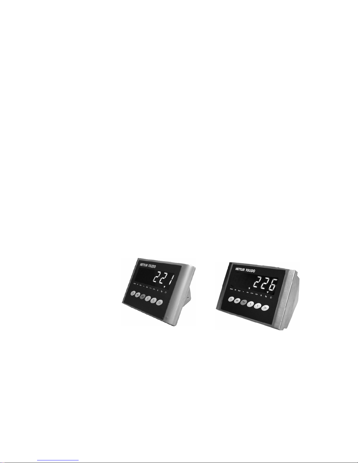
IND221
IND226
Industry Terminal
User/Service Manual
METTLER TOLEDO
182837 (2006-5-25)
PRECAUTIONS
WARNING
DISCONNECT ALL POWER TO THIS UNIT
BEFORE INSTALLING, SERVICING, CLEANING,
OR REMOVING THE FUSE. FAILURE TO DO SO
COULD RESULT IN BODILY HARM AND/OR
PROPERTY DAMAGE.
CAUTION
OBSERVE PRECAUTIONS FOR HANDLING
ELECTROSTATIC SENSITIVE DEVICES.
WARNING
ONLY PERMIT QUALIFIED PERSONNEL TO
SERVICE THIS EQUIPMENT. EXERCISE CARE
WHEN MAKING CHECKS, TESTS AND
ADJUSTMENTS THAT MUST BE MADE WITH
POWER ON. FAILING TO OBSERVE THESE
PRECAUTIONS CAN RESULT IN BODILY
HARM.
WARNING
FOR CONTINUED PROTECTION AGAINST
SHOCK HAZARD, CONNECT TO PROPERLY
GROUNDED OUTLET ONLY. DO NOT REMOVE
THE GROUND PRONG.
READ this manual BEFORE
operating or servicing this
equipment.
FOLLOW these instructions
carefully.
SAVE this manual for future
reference.
DO NOT allow untrained
p
ersonnel to operate, clean,
inspect, maintain, service, o
r
tamper with this equipment.
ALWAYS DISCONNECT this
equipment from the powe
r
source before cleaning o
r
p
erforming maintenance.
Note: If the unit has been stored or
transported in below freezing
temperatures, allow the unit to warm
up to room temperature before turnin
g
on AC power.
CAUTION
BEFORE CONNECTING OR DISCONNECTING ANY INTERNAL ELECTRONIC
COMPONENTS OR INTERCONNECTING WIRING BETWEEN ELECTRONIC
EQUIPMENT, ALWAYS REMOVE POWER AND WAIT AT LEAST THIRTY (30)
SECONDS BEFORE ANY CONNECTIONS OR DISCONNECTION’S ARE MADE.
FAILURE TO OBSERVE THESE PRECAUTIONS COULD RESULT IN DAMAGE
TO OR DESTRUCTION OF THE EQUIPMENT, OR BODILY HARM.
CAUTION
THE IND226 SOCKET-OUTLET SHALL BE INSTALLED NEAR THE
EQUIPMENT AND SHALL BE EASILY ACCESSIBLE.
CAUTION
RISK OF EXPLOSION IF BATTERY IS REPLACED BY EN INCORRECT TYPE.
DISPOSE OF USED BATTERIES ACCORDING TO THE INSTRUCTIONS
CAUTION
REMOVE THE BATTERY OUT IF THE TERMINAL WILL BE STORED IN A LONG
TIME.
CAUTION
REPLACE THE FUSES ONLY BY SERVICE PERSONNEL

In conformance with the European Directive 2002/96/ EC
on Waste Electrical and Electronic Equipment (WEEE) this
device may not be disposed of in domestic waste.
This also applies to countries outside the EU, per their
specific requirements.
Please dispose of this product in accordance with local
regulations at the collecting point specified for electrical and
electronic equipment.
If you have any questions, please contact the responsible
authority or the distributor from which you purchased this
device.
Should this device be passed on to other parties (for private
or professional use), the content of this regulation must also
be related.
Thank you for your contribution to environmental protection.

Contents
1.0 Overview................................................................................................................................1
1.1 Specification ....................................................................................................................... 1
1.2 Main functions....................................................................................................................1
1.3 Dimensions ......................................................................................................................... 2
1.4 Order information ............................................................................................................... 2
2.0 Install...................................................................................................................................... 3
2.1 Open the package................................................................................................................ 3
2.2 Electronic Connect.............................................................................................................. 3
2.2.1 Open the terminal................................................................................................. 3
2.2.2 Load Cell Connect................................................................................................ 3
2.2.3 Com1 RS232......................................................................................................... 4
2.3 Lead seal.............................................................................................................................4
2.4 Battery Pack Option............................................................................................................ 5
2.4.1 Battery install......................................................................................................... 5
2.4.2 Recharge Battery.................................................................................................. 5
2.4.3 Use Battery............................................................................................................ 5
3.0 Operation............................................................................................................................... 1
3.1 Operation HMI.............................................................................................................. ...... 1
3.2 Basic function operation..................................................................................................... 1
3.2.1 On/Off key.............................................................................................................. 1
3.2.2 Zero........................................................................................................................ 1
3.2.3 Tare......................................................................................................................... 1
3.2.4 Clear....................................................................................................................... 2
3.2.5 Print........................................................................................................................ 2
3.3 Expand functions ................................................................................................................ 2
3.3.1 X10 Function......................................................................................................... 2
3.3.2 Unit switch............................................................................................................. 2
3.3.3 Over/Under Function............................................................................................ 2
3.3.4
Counting Function................................................................................................ 4
4.0 Setup...................................................................................................................................... 1
4.1 Enter Setup.......................................................................................................................... 1
4.2 Keys in setup....................................................................................................................... 1
4.3 Setup Details..................................................................................................................... 10
5.0 Terminal Maintenance ....................................................................................................... 17
5.1 Daily maintenance ............................................................................................................ 17
5.2 Error Messages.................................................................................................................. 17
5.3 Software download ........................................................................................................... 18

1
1.0 Overview
1.1 Specification
z 6 digits 1.2” /30.5mm large green LED display. Robust long life.
z 6 Function keys, simple and easy.
z IND221: Plastic, Protection IP5x.
z IND226: Stainless steel, Protection: IP65.
z Executive voltage:+5VDC.
z Load Cell capability: Maximum 4-350ohm analog load cell.
z Zero signal input ranges: 0-5mV.
z SPAN signal input ranges: 1-10mV.
z Resolution: 1,000,000.
z Increments: 1,000 - 30,000
z A/D Rates: 27 /seconds.
z Working voltage: 100-240VAC, 0.1A
DC: NI-HM rechargeable battery (Optional)
DC: C Size Dry Battery (only for IND221)
z RS232 Serial port
z Working temperature: -10°C - +40°C, Relative Humidity < 90%.
z Storage temperature: -20°C - +60°C, Relative Humidity < 90%.
1.2 Main functions
z Basic weighing: Zero, Tare, Clear, Print.
z Auto print function.
z Units switch: kg, lb.
z x10 function / Simple check weighing / Counting.
z English/Chinese print formats.
z Support micro ticket printer PQ16.
z Power saving technology. Low battery icon.
z Auto power off.
z Software download
2
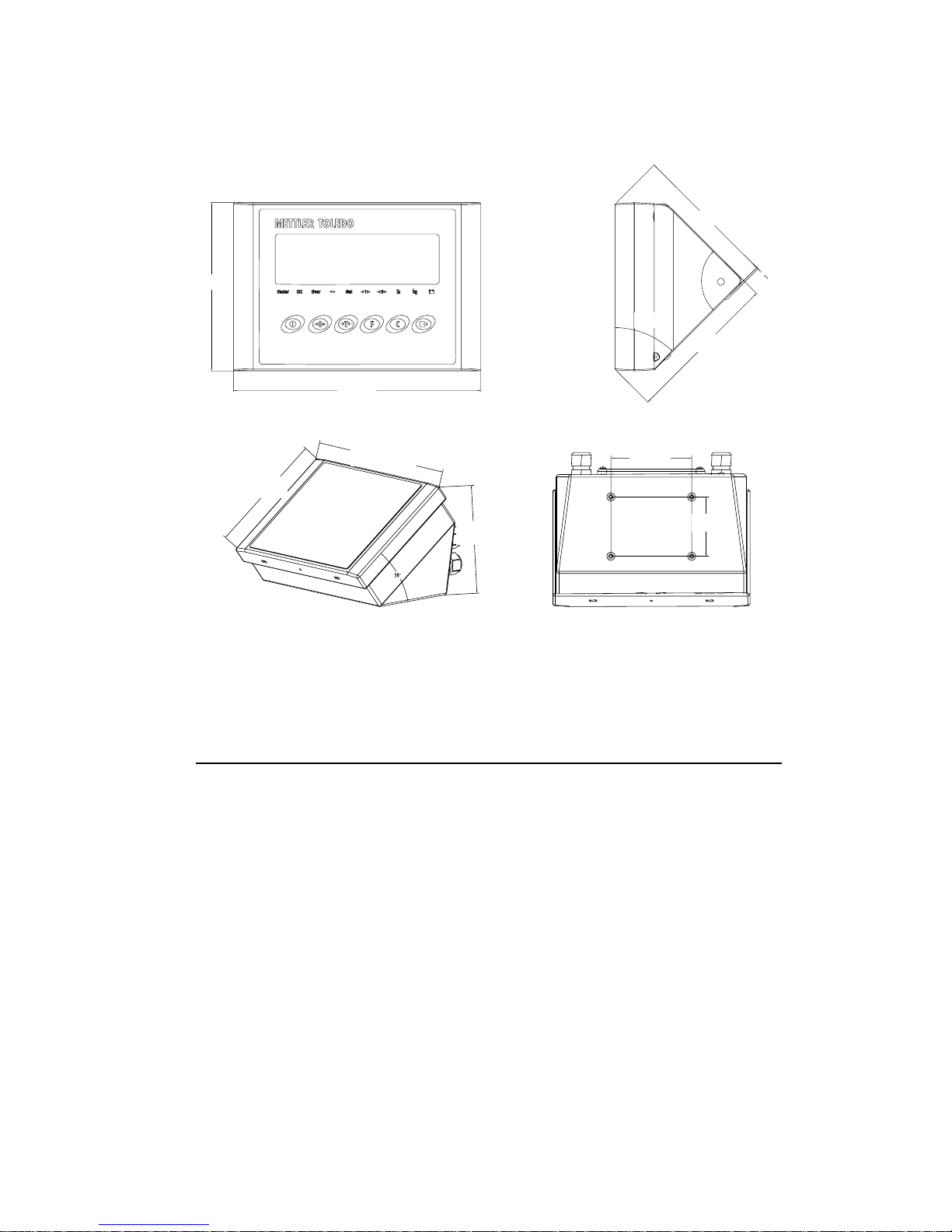
1.3 Dimensions
150mm
220mm
129.1mm
136.8mm
1.5
90°
45°
IND221
150mm
220mm
132mm
90mm
6
6mm
IND226
1.4 Order information
Model Name Descriptions P/N
IND221-1000 Plastic Standard(with dry battery case) 72183995
IND221-1001 Plastic With Ni-MH rechargeable battery 72183997
IND226-1000 Harsh, Standard 72183987
IND226-1001 Harsh, With Ni-MH rechargeable battery 72183989
3
2.0 Install
This part will talk about the installation for IND221 and IND226. Please read
this chapter carefully before install.
2.1 Open the package
Open the package, and check all the parts with the checklist. Make sure no
parts were damaged and missing.
Remove the terminal from its protective package.
2.2 Electronic Connect
2.2.1 Open the terminal
The IND221 terminal use 4 screws to lock the front cover.
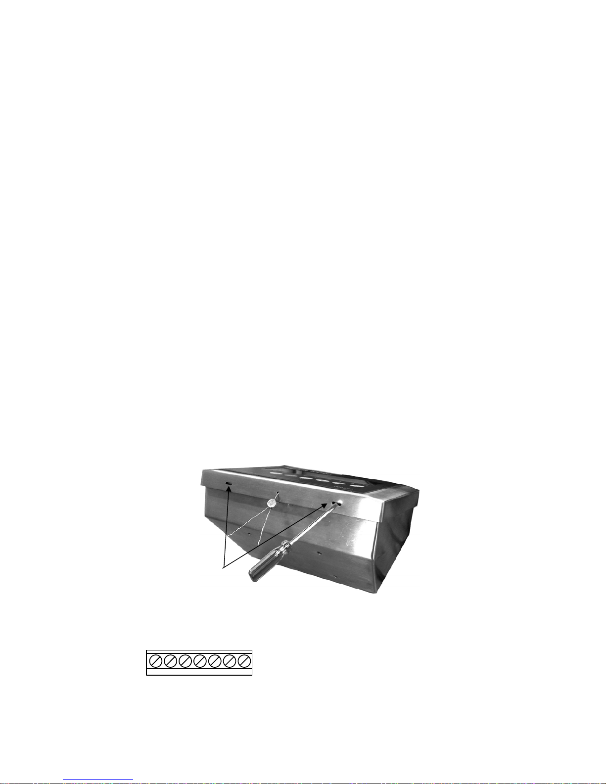
The front panel of the IND226 terminal is locked in place by four spring clips attached
to the enclosure body. To gain access to the terminal’s PCB for internal wiring and setting
switches, separate the front panel from the enclosure as follows:
Insert the tip of a flat-blade screwdriver into one of the two slots located on the bottom
of the front panel assembly and gently push in toward the enclosure. A “pop” sound is
made when the cover is released.
2.2.2 Load Cell Connect
7 Pins terminal strip.
Pin 1 - +EXC Pin 5 - -SIG
Pin 2 - +SEN Pin 6 - -SEN
Pin 3 - +SIG Pin 7 - -EXC
Pin 4 - Shield
1
+EXC
+SEN
+SIG
Shield
-SIG
-SEN
-EXC
 Loading...