

Mettler Toledo IND131, IND331 Installation Manual
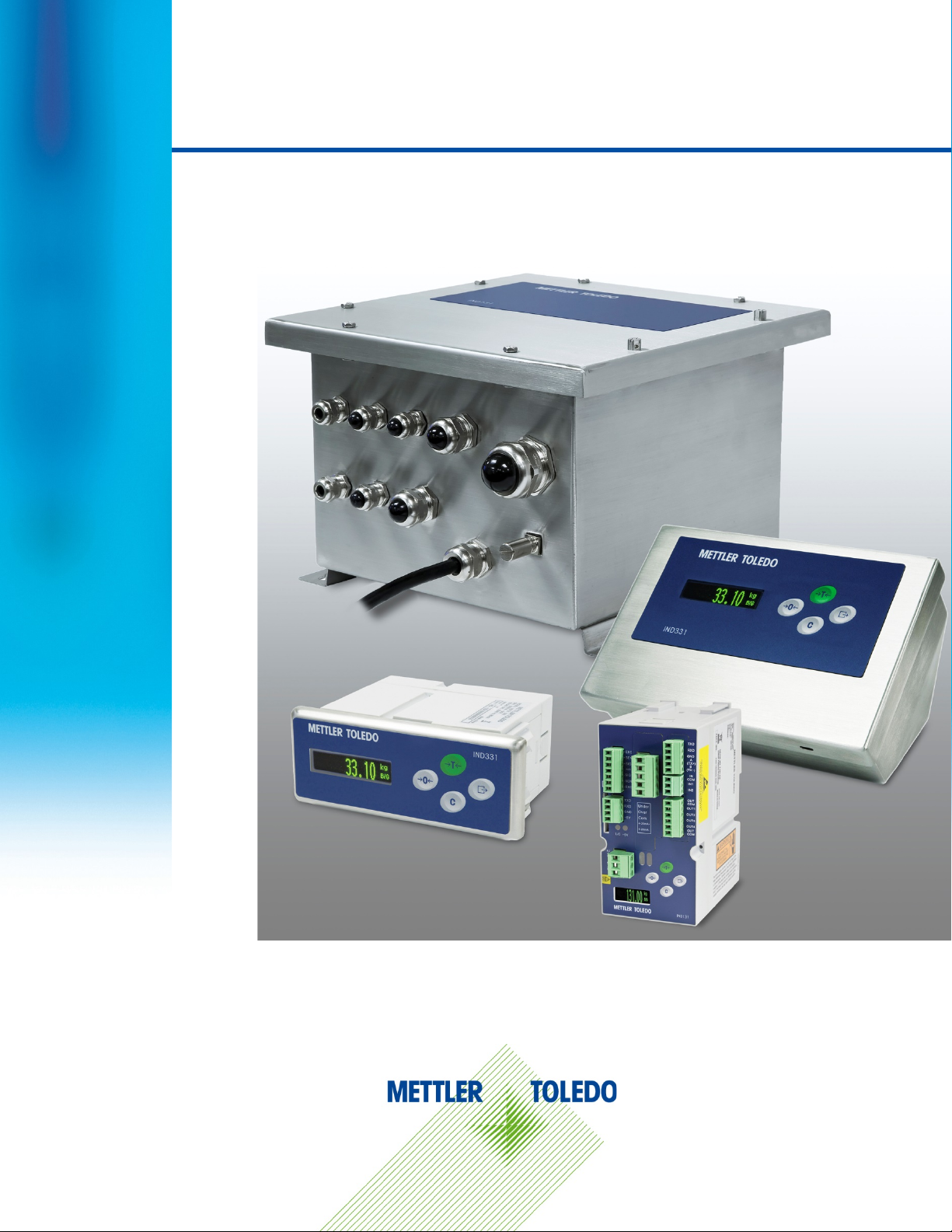
IND131/IND131xx/IND331/IND331xx
Weighing Terminal
/
Manual do instalação
Installation Manual / Guía de instalación / Installationsanleitung
Guide d’installation / Guida all’installazione /
Installation Manual

IND131/IND131xx/IND331/IND331xx
Essential Services for Dependable Performance of Your IND131/IND131xx/IND331/IND331xx
Weighing Terminal
Register your product
Contact METTLER TOLEDO for service
Installation, Configuration, Integration and Training
Initial Calibration Documentation
Periodic Calibration Maintenance
GWP® Verification
life-cycle management of weighing equipment
Weighing Terminal
Congratulations on choosing the quality and precision of METTLER TOLEDO. Proper use of your
new equipment according to this Manual and regular calibration and maintenance by our factorytrained service team ensures dependable and accurate operation, protecting your investment.
Contact us about a service agreement tailored to your needs and budget. Further information is
available at www.mt.com/service.
There are several important ways to ensure you maximize the performance of your investment:
1.
www.mt.com/productregistration so we can contact you about enhancements, updates and
important notifications concerning your product.
: We invite you to register your product at
2.
accuracy – an out of specification scale can diminish quality, reduce profits and increase
liability. Timely service from METTLER TOLEDO will ensure accuracy and optimize uptime and
equipment life.
a.
trained, weighing equipment experts. We make certain that your weighing equipment is
ready for production in a cost effective and timely fashion and that personnel are trained for
success.
b.
requirements are unique for every industrial scale so performance must be tested and
certified. Our calibration services and certificates document accuracy to ensure production
quality and provide a quality system record of performance.
c.
confidence in your weighing process and documentation of compliance with requirements.
We offer a variety of service plans that are scheduled to meet your needs and designed to
fit your budget.
d.
control and improvement of the entire measuring process, which ensures reproducible
product quality and minimizes process costs. GWP (Good Weighing Practice), the sciencebased standard for efficient
answers about how to specify, calibrate and ensure accuracy of weighing equipment,
independent of make or brand.
: A risk-based approach for managing weighing equipment allows for
: The value of a measurement is proportional to its
: Our service representatives are factory-
: The installation environment and application
: A Calibration Service Agreement provides on-going
, gives clear
© METTLER TOLEDO 2018
No part of this manual may be reproduced or transmitted in any form or by any means, electronic or
mechanical, including photocopying and recording, for any purpose without the express written
permission of METTLER TOLEDO.
U.S. Government Restricted Rights: This documentation is furnished with Restricted Rights.
Copyright 2018 METTLER TOLEDO. This documentation contains proprietary information of METTLER
TOLEDO. It may not be copied in whole or in part without the express written consent of METTLER
TOLEDO.
METTLER TOLEDO reserves the right to make refinements or changes to the product or manual
without notice.
COPYRIGHT
METTLER TOLEDO® is a registered trademark of Mettler-Toledo, LLC. All other brand or product
names are trademarks or registered trademarks of their respective companies.
METTLER TOLEDO RESERVES THE RIGHT TO MAKE REFINEMENTS OR CHANGES
WITHOUT NOTICE.
FCC Notice
This device complies with Part 15 of the FCC Rules and the Radio Interference Requirements of the
Canadian Department of Communications. Operation is subject to the following conditions: (1) this
device may not cause harmful interference, and (2) this device must accept any interference
received, including interference that may cause undesired operation.
This equipment has been tested and found to comply with the limits for a Class A digital device,
pursuant to Part 15 of FCC Rules. These limits are designed to provide reasonable protection against
harmful interference when the equipment is operated in a commercial environment. This equipment
generates, uses, and can radiate radio frequency energy and, if not installed and used in
accordance with the instruction manual, may cause harmful interference to radio communications.
Operation of this equipment in a residential area is likely to cause harmful interference in which case
the user will be required to correct the interference at his or her expense.
Declaration of Conformity is located on the documentation CD.
RoHS Compliance Statement.
The majority of our products fall within categories 8 and 9. Those categories currently do not fall
within the scope of the Directive 2002/95/EG (RoHS) of January 27, 2003. If our products are
intended for use in other products which themselves fall within the scope of the RoHS Directive,
compliance requirements have to be separately negotiated contractually.
Those products which fall within categories 1-7 and 10 will be in compliance with the EU RoHS
Directive from no later than July 1, 2006.
If it is not possible for technical reasons to replace any non-RoHS-compliant substances in any of
the above products as required, we plan to inform our customers in a timely manner
Statement regarding harmful substances
We do not make direct use of harmful materials such as asbestos, radioactive substances or
arsenic compounds. However, we purchase components from third party suppliers, which may
contain some of these substances in very small quantities.
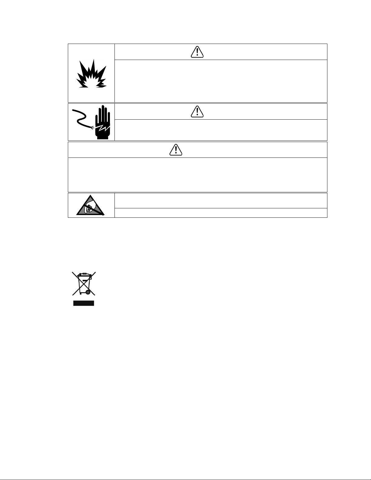
Warnings and Cautions
• READ this manual BEFORE operating or servicing this equipment and FOLLOW these
instructions carefully.
• SAVE this manual for future reference.
WARNING
FOR CONTINUED PROTECTION AGAINST SHOCK HAZARD CONNECT THE AC VERSION OF THE
HARSH AND JUNCTION BOX ENCLOSURES TO PROPERLY GROUNDED OUTLET ONLY. DO NOT
REMOVE THE GROUND PRONG.
WARNING
WHEN THIS EQUIPMENT IS INCLUDED AS A COMPONENT PART OF A SYSTEM, THE
RESULTING DESIGN MUST BE REVIEWED BY QUALIFIED PERSONNEL WHO ARE FAMILIAR
WITH THE CONSTRUCTION AND OPERATION OF ALL COMPONENTS IN THE SYSTEM AND THE
POTENTIAL HAZARDS INVOLVED. FAILURE TO OBSERVE THIS PRECAUTION COULD RESULT IN
BODILY HARM AND/OR PROPERTY DAMAGE.
WARNING
ENSURE THAT THE POWER CONNECTION TO THE IND131 OR IND331 TERMINAL MATCHES
THE SPECIFIED OPERATING VOLTAGE OF THAT TERMINAL. REFER TO THE DATA LABEL OF THE
TERMINAL FOR THE OPERATING VOLTAGE. CONNECTING THE INCORRECT POWER SOURCE
TO THE TERMINAL COULD RESULT IN DAMAGE TO OR DESTRUCTION OF THE EQUIPMENT
AND/OR BODILY HARM.
WARNING
THE IND131, IND131xx, IND331 AND IND331xx TERMINALS ARE NOT INTRINSICALLY
SAFE. DO NOT USE WITHIN AREAS CLASSIFIED AS HAZARDOUS DIVISION 1 OR ZONES
0/1/20/21 BECAUSE OF COMBUSTIBLE OR EXPLOSIVE ATMOSPHERES. FAILURE TO
COMPLY WITH THIS WARNING COULD RESULT IN BODILY HARM AND/OR PROPERTY
DAMAGE.
WARNING
IF THE KEYBOARD, DISPLAY LENS OR ENCLOSURE IS DAMAGED ON AN IND131xx OR
IND331xx TERMINAL THAT IS USED IN A DIVISION 2 OR ZONE 2/22 AREA, THE DEFECTIVE
COMPONENT MUST BE REPAIRED IMMEDIATELY. REMOVE POWER IMMEDIATELY AND DO
NOT REAPPLY POWER UNTIL THE DISPLAY LENS, KEYBOARD OR ENCLOSURE HAS BEEN
REPAIRED OR REPLACED BY QUALIFIED SERVICE PERSONNEL. FAILURE TO DO SO COULD
RESULT IN BODILY HARM AND/OR PROPERTY DAMAGE.
WARNING
IND131xx AND IND331xx TERMINALS USED IN A DIVISION 2 OR ZONE 2/22 ENVIRONMENT
MUST BE INSTALLED AND MAINTAINED PER THE SPECIAL CONDITIONS LISTED IN CHAPTER
2 OF THE IND131xx AND IND 331xx DIVISION 2 INSTALLATION MANUAL (64068795)
WITHOUT EXCEPTION. FAILURE TO DO SO COULD RESULT IN BODILY HARM AND/OR
PROPERTY DAMAGE.
WARNING
METTLER TOLEDO ASSUMES NO RESPONSIBILITY FOR CORRECT INSTALLATION OF THIS
EQUIPMENT WITHIN A DIVISION 2 OR ZONE 2/22 AREA. THE INSTALLER MUST BE
FAMILIAR WITH ALL DIVISION 2 OR ZONE 2/22 WIRING AND INSTALLATION
REQUIREMENTS.
WARNING
THE IND131XX AND IND331XX TERMINALS HAVE BEEN APPROVED BY FM (US AND
CANADA) WITH A TEMPERATURE RATING OF T5 (100˚ C) FOR USE IN HAZARDOUS
ENVIRONMENTS. THEY HAVE BEEN CERTIFIED BY KEMA (ATEX AND IECEx) WITH A
TEMPERATURE RATING OF T5 (100˚ C) FOR GAS ENVIRONMENTS AND A T RATING OF
100°C FOR DUST ENVIRONMENTS. THEY MUST NOT BE USED IN AREAS WHERE THE AUTO
IGNITION TEMPERATURE OF THE HAZARDOUS MATERIAL IS BELOW THIS RATING.
WARNING
NON-APPROVED MODELS OF THE IND131 AND IND331 TERMINAL THAT ARE NOT
FACTORY-LABELED AS DIVISION 2 OR ZONE 2/22 APPROVED MUST NOT BE INSTALLED
INTO A DIVISION 2 OR ZONE 2/22 ENVIRONMENT.
WARNING
Warnings and Cautions
IN ORDER TO INSTALL THE IND131xx OR IND331xx TERMINAL UTILIZING THE U.S. OR
CANADIAN FM APPROVAL, METTLER TOLEDO CONTROL DRAWING 72238303R MUST BE
FOLLOWED WITHOUT EXCEPTION. IN ORDER TO INSTALL THE CATEGORY 3 MARKED
IND131xx OR IND331xx TERMINAL UTILIZING THE EUROPEAN ATEX APPROVAL, THE TYPE
EXAMINATION CERTIFICATE KEMA 10ATEX0097 X, DRAWING 72246295R AND ALL LOCAL
REGULATIONS MUST BE FOLLOWED WITHOUT EXCEPTION. IN ORDER TO INSTALL THE
IND131xx OR IND331xx TERMINAL UTILIZING THE iECEx APPROVAL, THE CERTIFICATE OF
CONFORMITY IECEx KEM 10.0060X AND ALL LOCAL REGULATIONS MUST BE FOLLOWED
WITHOUT EXCEPTION. FAILURE TO DO SO COULD RESULT IN BODILY HARM AND/OR
PROPERTY DAMAGE.
WARNING
THE INTERNAL DISCRETE I/O RELAY OPTION (#72225753 OR #72225757) MUST NOT BE
USED IN A TERMINAL INSTALLED IN AN AREA CLASSIFIED AS DIVISION 2 OR ZONE 2/22.
FAILURE TO COMPLY WITH THIS WARNING COULD RESULT IN BODILY HARM AND/OR
PROPERTY DAMAGE.
WARNING
THE CC-LINK PLC OPTION (#30059622) MUST NOT BE USED IN A TERMINAL INSTALLED
IN AN AREA CLASSIFIED AS DIVISION 2 OR ZONE 2/22 (IND131xx/IND331xx). FAILURE TO
COMPLY WITH THIS WARNING COULD RESULT IN BODILY HARM AND/OR PROPERTY
DAMAGE.
WARNING
THE CONTROLNET™ PLC OPTION (64057423) MUST NOT BE USED IN AC VERSIONS OF
IND131 AND IND331 TERMINALS. FAILURE TO COMPLY WITH THIS WARNING COULD
RESULT IN EQUIPMENT DAMAGE AND/OR BODILY HARM.
WARNING
In conformance with the European Directive 2002/96/EC on Waste Electrical and Electronic
ONLY THE DC POWERED VERSIONS OF THE DIN, PANEL-MOUNT AND J-BOX ENCLOSURES
OF THE IND131xx AND IND331xx TERMINALS HAVE BEEN APPROVED FOR USE IN
DIVISION 2 AND ZONE 2/22 ENVIRONMENTS. THE HARSH ENCLOSURE IND331 DC
POWERED TERMINAL AND ALL AC POWERED VERSIONS OF THE IND131 AND IND331
TERMINALS DO NOT HAVE A DIVISION 2 OR ZONE 2/22 APPROVAL AND MUST NOT BE
INSTALLED IN DIVISION 2 ENVIRONMENTS OR IN ZONE 2/22 ENVIRONMENTS.
WARNING
DISCONNECT ALL POWER TO THIS UNIT BEFORE INSTALLING, SERVICING, OR CLEANING.
FAILURE TO DO SO COULD RESULT IN BODILY HARM AND/OR PROPERTY DAMAGE.
CAUTION
BEFORE CONNECTING/DISCONNECTING ANY INTERNAL ELECTRONIC COMPONENTS OR INTERCONNECTING
WIRING BETWEEN ELECTRONIC EQUIPMENT ALWAYS REMOVE POWER AND WAIT AT LEAST THIRTY (30)
SECONDS BEFORE ANY CONNECTIONS OR DISCONNECTIONS ARE MADE. FAILURE TO OBSERVE THESE
PRECAUTIONS COULD RESULT IN DAMAGE TO OR DESTRUCTION OF THE EQUIPMENT AND/OR BODILY HARM.
NOTICE
OBSERVE PRECAUTIONS FOR HANDLING ELECTROSTATIC SENSITIVE DEVICES.
Disposal of Electrical and Electronic Equipment
Equipment (WEEE) this device may not be disposed of in domestic waste. This also applies
to countries outside the EU, per their specific requirements.
Please dispose of this product in accordance with local regulations at the collecting point
specified for electrical and electronic equipment.
If you have any questions, please contact the responsible authority or the distributor from
which you purchased this device.
Should this device be passed on to other parties (for private or professional use), the
content of this regulation must also be related.
Thank you for your contribution to environmental protection.

64067480 | 11 | 05/2018
METTLER TOLEDO IND131/131xx/IND331/331xx Installation Manual
1
Contents
1 Introduction ................................................................................. 1-1
1.1. Overview ...................................................................................... 1-1
1.1.1. Standard Features ............................................................................................... 1-1
1.2. Terminal Versions ......................................................................... 1-2
1.3. Specifications ............................................................................... 1-3
1.4. Use in Hazardous Areas ................................................................. 1-6
1.5. Inspection and Contents Checklist ................................................... 1-6
1.6. Model Identification ....................................................................... 1-7
1.7. Physical Dimensions ..................................................................... 1-8
1.8. Main PCB .................................................................................. 1-11
1.9. Scale Base ................................................................................. 1-11
1.10. Options ...................................................................................... 1-11
1.10.1. COM2 Serial Port ............................................................................................... 1-11
1.10.1.1. Modbus RTU .................................................................................................................. 1-12
1.10.2. Discrete I/O ....................................................................................................... 1-12
1.10.3. PLC Interfaces ................................................................................................... 1-12
1.10.3.1. Analog Output ................................................................................................................ 1-12
1.10.3.2. A-B RIO ......................................................................................................................... 1-12
1.10.3.3. CC-Link ......................................................................................................................... 1-13
1.10.3.4. ControlNet ..................................................................................................................... 1-13
1.10.3.5. EtherNet/IP and Modbus TCP ........................................................................................... 1-13
1.10.3.6. DeviceNet ...................................................................................................................... 1-13
1.10.3.7. PROFIBUS DP ................................................................................................................ 1-14
1.10.4. SD Memory Option ............................................................................................ 1-14
1.11. Display and Keyboard ................................................................. 1-14
1.11.1. Display Layout .................................................................................................. 1-15
1.11.2. Front Panel Keys ............................................................................................... 1-15
2. Installation .................................................................................. 2-1
2.1. Opening the Enclosures ................................................................. 2-2
2.1.1. IND131 DIN and IND331 Panel-mount ................................................................. 2-2
2.1.2. IND131 J-Box..................................................................................................... 2-3
2.1.3. IND131 J-Box, Updated ....................................................................................... 2-3
2.1.4. IND331 Harsh .................................................................................................... 2-4
2.2. Mounting the Terminals ................................................................. 2-4
2.2.1. IND131 DIN Module ............................................................................................ 2-4
2.2.2. IND331 Panel Mount ........................................................................................... 2-6
2.2.3. Direct Mounting ................................................................................................... 2-7
2.2.4. Remote Mounting ................................................................................................ 2-8
2.2.5. IND131 J-Box................................................................................................... 2-11
2.2.6. IND331 Harsh Enclosure ................................................................................... 2-11

2
METTLER TOLEDO IND131/131xx/IND331/331xx Installation Manual
64067480 | 11 | 05/2018
2.2.6.1. Desktop Mounting .......................................................................................................... 2-11
2.2.6.2. Harsh Enclosure Wall Mounting ....................................................................................... 2-12
2.3. Installing Cables and Connectors .................................................. 2-14
2.3.1. Ferrite ............................................................................................................... 2-14
2.3.2. Cable Glands .................................................................................................... 2-15
2.3.2.1. Positions and Assignments ............................................................................................. 2-15
2.3.2.2. Shield Termination.......................................................................................................... 2-16
2.3.2.3. Sealing the Gland ........................................................................................................... 2-17
2.4. Main Board Wiring Connections .................................................... 2-18
Contents
2.4.1. Power Connection ............................................................................................. 2-19
2.4.1.1. AC Powered Units ........................................................................................................... 2-19
2.4.1.2. DC Powered Units .......................................................................................................... 2-20
2.4.2. Load Cell Connections ....................................................................................... 2-20
2.4.2.1. Load Cell System Resistance ........................................................................................... 2-21
2.4.2.2. DIN, Panel-mount and Harsh Enclosures .......................................................................... 2-21
2.4.2.3. Junction-Box Enclosures ................................................................................................. 2-22
2.4.3. COM1 Serial Port Connections ............................................................................ 2-26
2.4.4. Panel Mount Display Wiring ............................................................................... 2-27
2.4.5. Wiring Connections for Options ........................................................................... 2-28
2.4.5.1. COM2 Connections......................................................................................................... 2-28
2.4.5.2. Discrete I/O (Relay) Connections ...................................................................................... 2-29
2.4.5.3. Discrete I/O (Solid State) Connections ............................................................................... 2-32
2.4.5.4. Analog Output Connections ............................................................................................. 2-34
2.4.5.5. Allen Bradley RIO ........................................................................................................... 2-35
2.4.5.6. CC-Link Interface ............................................................................................................ 2-35
2.4.5.7. ControlNet Interface ........................................................................................................ 2-37
2.4.5.8. DeviceNet ...................................................................................................................... 2-39
2.4.5.9. Ethernet / IP and Modbus TCP Interface ............................................................................. 2-40
2.4.5.10. PROFIBUS DP ................................................................................................................ 2-41
2.5. Main PCB Switch Settings ............................................................ 2-44
2.5.1. Metrology Approval ............................................................................................ 2-44
2.5.2. Master Reset ..................................................................................................... 2-45
2.5.3. Firmware Flash ................................................................................................. 2-45
2.5.4. Reset Calibration ............................................................................................... 2-45
2.5.5. Factory Test Mode ............................................................................................. 2-45
2.6. Closing the Enclosure .................................................................. 2-45
2.6.1. DIN and Panel Mount ........................................................................................ 2-45
2.6.2. Junction Box..................................................................................................... 2-46
2.6.2.1. Original Version ............................................................................................................. 2-46
2.6.2.2. Updated Version ............................................................................................................. 2-47
2.6.3. Harsh Environment Enclosure ............................................................................. 2-47
2.7. Capacity Label Instructions ........................................................... 2-48
2.8. Metrological Sealing .................................................................... 2-49
64067480 | 11 | 05/2018
METTLER TOLEDO IND131/IND131x/IND331/IND331xx Installation Manual
1-1
This chapter covers
1 Introduction
DIV 2 AND ZONE 2/22 INSTALLATION
IF YOU WISH TO INSTALL THE IND131xx OR IND331xx TERMINAL IN A DIVISION 2 OR ZONE 2/22 AREA, REFER
TO THE DIVISION 2 AND ZONE 2/22 INSTALLATION INSTRUCTIONS INCLUDED ON THE RESOURCE CD
PROVIDED WITH THE TERMINAL. FAILURE TO COMPLY WITH THE INSTRUCTIONS PROVIDED THERE COULD
RESULT IN BODILY HARM AND/OR PROPERTY DAMAGE.
The IND131, IND131xx, IND331 and IND331xx industrial scale terminals provide a
• Overview
• Terminal Versions
• Specifications
• Use in Hazardous Areas
• Inspection and Contents
Checklist
• Model Identification
• Physical Dimensions
• Main PCB
• Scale Bases
• Options
•
Display and Keyboard
compact but flexible solution to a variety of weighing needs. Configured in a variety
of enclosure types, these terminals are at home in virtually any industrial
environment. They are optimized for ease of integration into existing weighing
systems, and their modular construction makes for simplicity of maintenance.
Innovative use of Secure Data (SD) Memory technology permits quick, simple
replacement of a terminal, complete with all its calibration and configuration settings.
Both 2mv/V and 3mv/V load cells are supported without the need for any
configuration change. Measurement and control applications are enhanced with an
ultra-fast A/D conversion rate, patented TraxDSP™ digital filtering technology, and
discrete I/O update rate of 50 Hz. The IND131, IND131xx, IND331 and IND331xx
deliver precision measurement data from grams to tons in a single cost effective
package.
Whether communicating weight data to a process PLC or providing a serial output of
data to a printer, the terminals offer solutions for a wide range of applications.
1.1. Overview
1.1.1. Standard Features
• Modular design, multiple mounting methods
• Supports one analog load cell platform (The DC version supports up to four 350 ohm load
cells in legal for trade applications globally. The AC version supports up to eight 350 ohm
load cells in legal for trade applications in the US. The AC version in Europe and the rest of
the world supports up to four for legal for trade applications and maximum eight 350 ohm
load cells in non-legal for trade applications.)
• Ability to position the IND331 panel-mount display remotely from the DIN terminal module
• Organic LED (OLED) displays for crisp readability in all light conditions
• One serial port for asynchronous, bidirectional communication and print output
• Powered by either 85–264 V AC or 24 V DC (selected by model)

1-2
METTLER TOLEDO IND131/IND131x/IND331/IND331xx Installation Manual
64067480 | 11 | 05/2018
• Support for the following option boards:
COM2 and Discrete I/O interface (includes Modbus RTU protocol)
Choice of one PLC interface:
o 4-20mA Analog Output
®
o Allen Bradley RIO
o CC-Link
o ControlNet™ (for DC version only)
o DeviceNet™
o Ethernet/IP
Introduction
• Front panel key access to basic weighing functions – zero, tare, clear and print
• Latching target control to provide one- or two-speed feeding control with the press of a start
o Modbus TCP
®
o PROFIBUS
DP
button
• Rate calculation used for comparator source or communicated to a PLC
• Comparators - simple coincidence setpoints for comparison of weight or rate with absolute
target values or ranges
• Selectable unit of measure including grams, kilograms, pounds, tons
• Backup and restore of configuration and calibration settings, using SD memory device or
InSite™ PC tool
• TraxEMT™ performance monitoring and recording
• CalFREE™ calibration without test weights
• Scale calibration via A-B RIO, CC-Link, ControlNet, DeviceNet, Ethernet/IP, Modbus RTU and
Modbus TCP, and PROFIBUS interfaces.
• Models IND131xx and IND331xx are certified for use within hazardous (explosive) areas
classified as Division 2 or Zone 2 or 22.
1.2. Terminal Versions
The terminals are available in the following versions:
• IND131 DIN rail mount, AC power
• IND131 DIN rail mount, 24 VDC power
• IND131xx DIN rail mount, 24 VDC power, Division 2 and Zone 2/22 certified
• IND331 Panel-mount, AC power
• IND331 Panel-mount, 24 VDC power
• IND331xx Panel-mount, 24 VDC power, Division 2 and Zone 2/22 certified
• IND331 Harsh, AC power

64067480 | 11 | 05/2018
METTLER TOLEDO IND131/IND131x/IND331/IND331xx Installation Manual
1-3
• IND331 Harsh, 24 VDC power
Enclosure Type
Dimensions (w × h × d)
Shipping Weight
• IND131 Junction Box, AC power
• IND131 Junction Box, 24 VDC power
• IND131xx Junction Box, 24 VDC power, Division 2 and Zone 2/22 certified
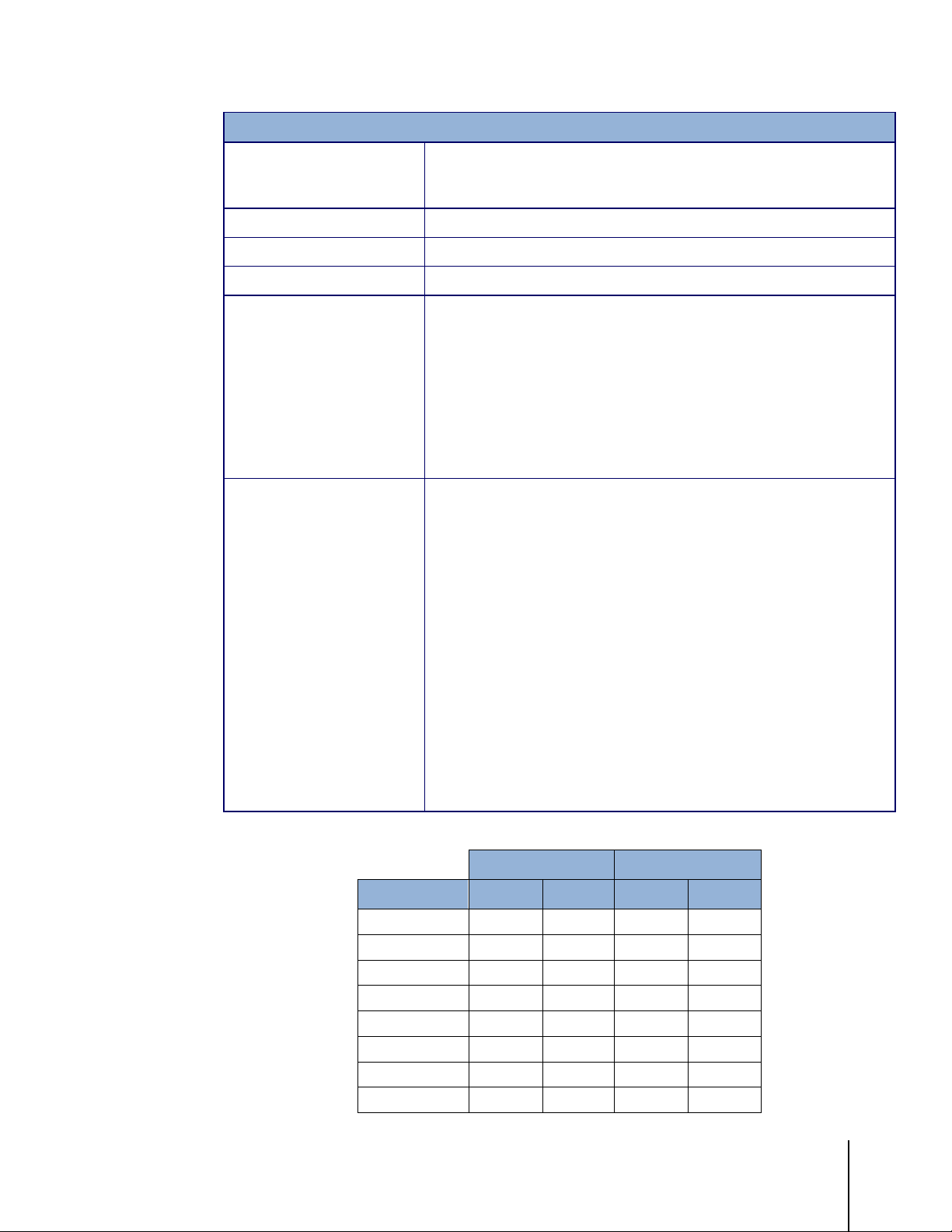
1.3. Specifications
The terminals conform to the specifications listed in Table 1-1.
Table 1-1: Terminal Specifications
IND131 and IND331 Specifications
IND131 DIN rail-mount: plastic housing with operator interface
IND331 Panel-mount: Stainless steel front panel with operator interface.
Plastic rear chassis that can be mounted to the display or remotely DIN rail
mounted.
IND331 Harsh: Stainless steel desk top or wall mount enclosure including
operator interface.
IND131 J-Box: Stainless steel enclosure including internal board for
summing four load cells.
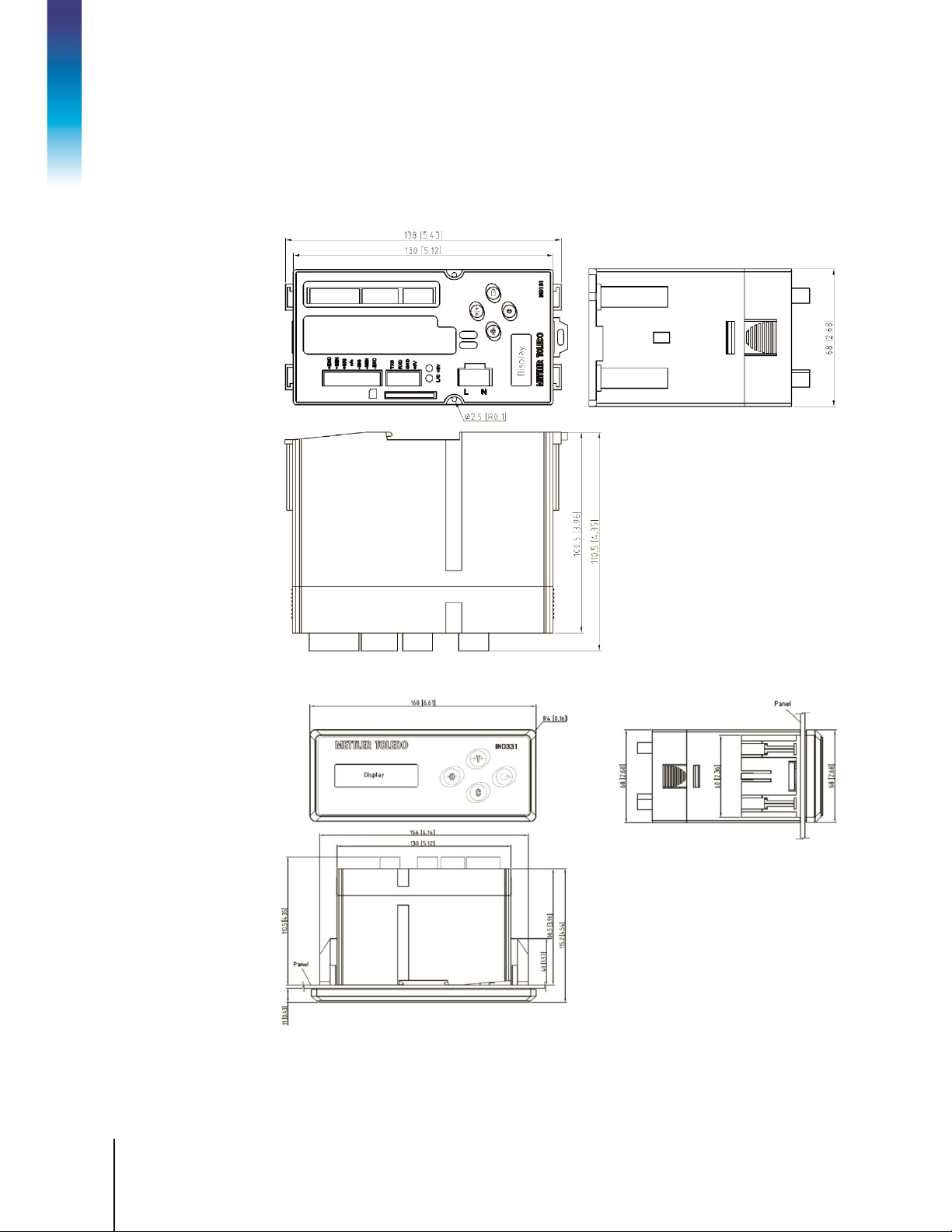
IND131 DIN module: 68 mm × 138 mm × 111 mm
(2.7 in. × 5.4 in. × 4.4 in.)
IND331 Panel-mount:
Front panel: 168 mm × 68 mm × 12 mm
(6.6 in. × 2.7 in. × 0.5 in.)
Rear chassis: 156 mm x 68 mm x 111 mm
(6.1 in. x 2.7 in. x 4.4 in.)
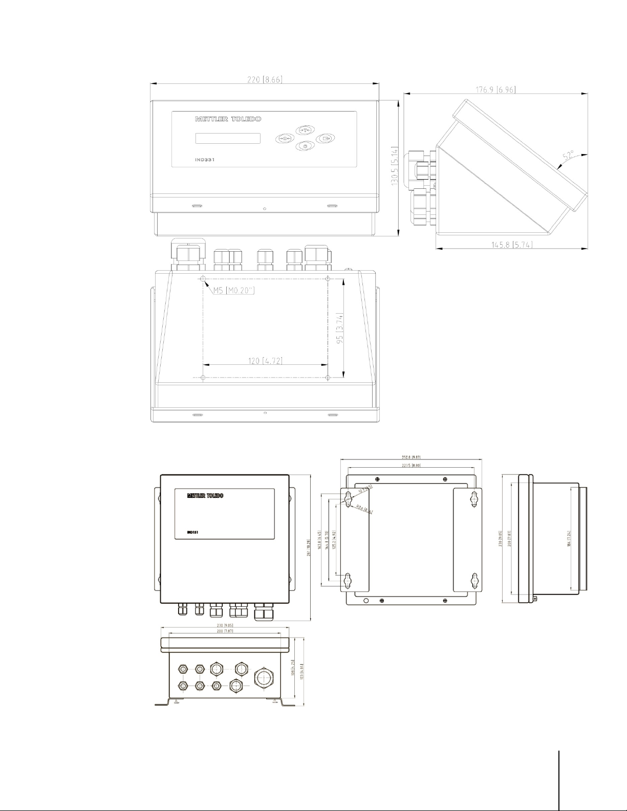
IND331 Harsh: 220 mm x 131 mm x 177 mm
(8.7 in. x 5.2 in. x 7.0 in.)
IND131 J-Box: 251 mm x 261 mm x 123 mm
(9.9 in. x 10.3 in. x 4.8 in.) Original design.
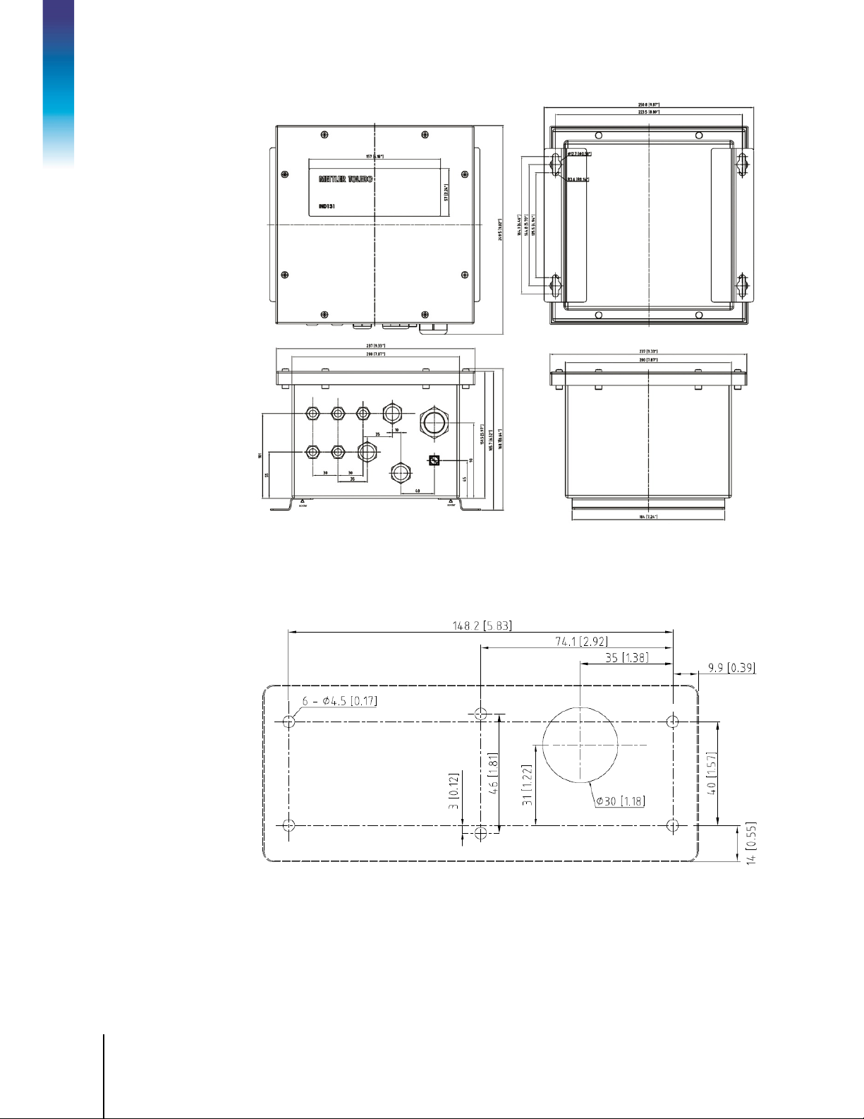
IND131 J-Box: 251 mm x 261 mm x 169 mm
(9.9 in. x 10.3 in. x 6.6 in.) Updated design.
IND131 DIN: 1 kg (2.2 lb)
IND331 Panel: 1.5 kg (3.3 lb)
IND331 Harsh: 3 kg (6.5 lb)
IND131 J-Box: 5.5 kg (12.1 lb)

1-4
METTLER TOLEDO IND131/IND131x/IND331/IND331xx Installation Manual
64067480 | 11 | 05/2018
Environmental Protection
Operating Environment
Hazardous Areas
Power
Power Consumption
Display
Weight Display
Scale Types
Number of Cells
Number of Scales
IND131 and IND331 Specifications
IND131/IND131xx DIN: IP20, Type 1
IND131 J-Box: IP69K
IND131xx J-Box: IP65
IND331/IND331xx Panel: IP65, Type 4x and12
IND331 Harsh: IP66
The terminal (all enclosure types) can be operated at temperatures ranging
from −10° to 40° C (14° to 104° F) at 10% to 95% relative humidity,
non-condensing.
Introduction
The standard IND131/IND331 terminal cannot be operated in areas
classified as Hazardous because of combustible or explosive atmospheres
in those areas. Special models IND131xx and IND331xx are designed for
use within Division 2 or Zone 2/22 areas. None of the IND131/331 family
of terminals is designed for use within Division 1 or Zone 0/1/20/21 areas.
Contact an authorized METTLER TOLEDO representative for information
about hazardous area applications.
AC version: Operates at 100 -- 240 VAC, 49–61 Hz
DC version: Operates from 18 to 36 VDC
All DC versions and AC versions of the DIN and panel-mount models
provide a terminal strip for power connections.
AC versions of the harsh environment and junction box models include a
power cord configured for the country of use.
Note: When an IND131xx or IND331xx terminal is installed into an area
classified as Division 2 or zone 2/22, special AC wiring requirements must
be met. Refer to document 64068795 Division 2 and Zone 2/22
Installation Guide. Provisions must be made to prevent transient
disturbances of more than 40% from the DC voltage supplied to the
IND131xx and IND331xx terminals.
Refer to Table 1-2 and Table 1-3
Green OLED including weight display, weight units, gross/net indication
and graphic symbols for motion and center of zero. Also used for
programming. Update rate of 10 updates per second.
IND131: 5.6 mm (0.22 in) high weight display
IND331: 12 mm (0.47 in) high weight display
Maximum displayed resolution of 100,000 divisions.
Analog load cells
DC Version: Up to four 350-ohm load cells (2 or 3 mv/V)
AC Version:
One
Up to eight 350-ohm load cells (2 or 3 mv/V), approved in the US.
Up to four for legal for trade applications in Europe and the rest of the
world, eight maximum in non-legal for trade applications.
64067480 | 11 | 05/2018
METTLER TOLEDO IND131/IND131x/IND331/IND331xx Installation Manual
1-5
IND131 and IND331 Specifications
Analog/Digital Update Rates
Load Cell Excitation Voltage
Minimum Sensitivity
Keypad
Communications
Approvals
Internal analog: 366 Hz
Target Comparison: 50 Hz;
PLC Interface: 20 Hz
5 V DC
0.1 microvolts
4 keys; polyester overlay (PET) with polycarbonate display lens
Serial Interfaces
Standard: One serial port (COM1) RS-232, 300 to 115,200 baud
Optional Serial Port: (COM2) RS-232/485, 300 to 115,200 baud
Protocol
Serial Inputs:, ASCII commands for CTPZ (Clear, Tare, Print, Zero), SICS
(most level 0 and level 1 commands)
Serial Outputs: Continuous, Extended continuous, Demand (limited
formats) or SICS. Optional COM2 provides Modbus RTU.
Weights and Measures
USA: NTEP Class III/IIIL,10,000d - CoC 09-051
Canada: Class III - 10,000d; Class IIIHD - 20,000d;
AM-5744
Europe: Class III, 6000 e - TC7600
Gravimetric Filling (MID) – T10261
Catchweighing (MID) – T10262
OIML: Class III, 6000 e - R76/2006-NL1-09.26
Product Safety
UL, cUL, CE Note: When an IND131xx or IND331xx terminal is installed
into an area classified as Division 2 or zone 2/22, special AC wiring
requirements must be met. Refer to document 64068795 Division 2 and
Zone 2/22 Installation Guide. Provisions must be made to prevent
transient disturbances of more than 40% from the DC voltage supplied to
the IND131xx and IND331xx terminals.
Table 1-2: IND131, IND331 Power Consumption (AC Source)
Input Voltage I (mA) P (W) I (mA) P (W)
85V/50 Hz 73 3.3 79 3.5
110 V/50 Hz 58 3.3 63 3.5
240 V/50 Hz 28 3.3 30 3.6
264 V/50 Hz 27 3.4 28 3.6
85 V/60 Hz 70 3.3 75 3.5
110 V/60 Hz 56 3.3 60 3.5
240 V/60 Hz 27 3.4 30 3.6
264 V/60 Hz 27 3.5 28 3.8
IND131 IND331
1-6
METTLER TOLEDO IND131/IND131x/IND331/IND331xx Installation Manual
64067480 | 11 | 05/2018
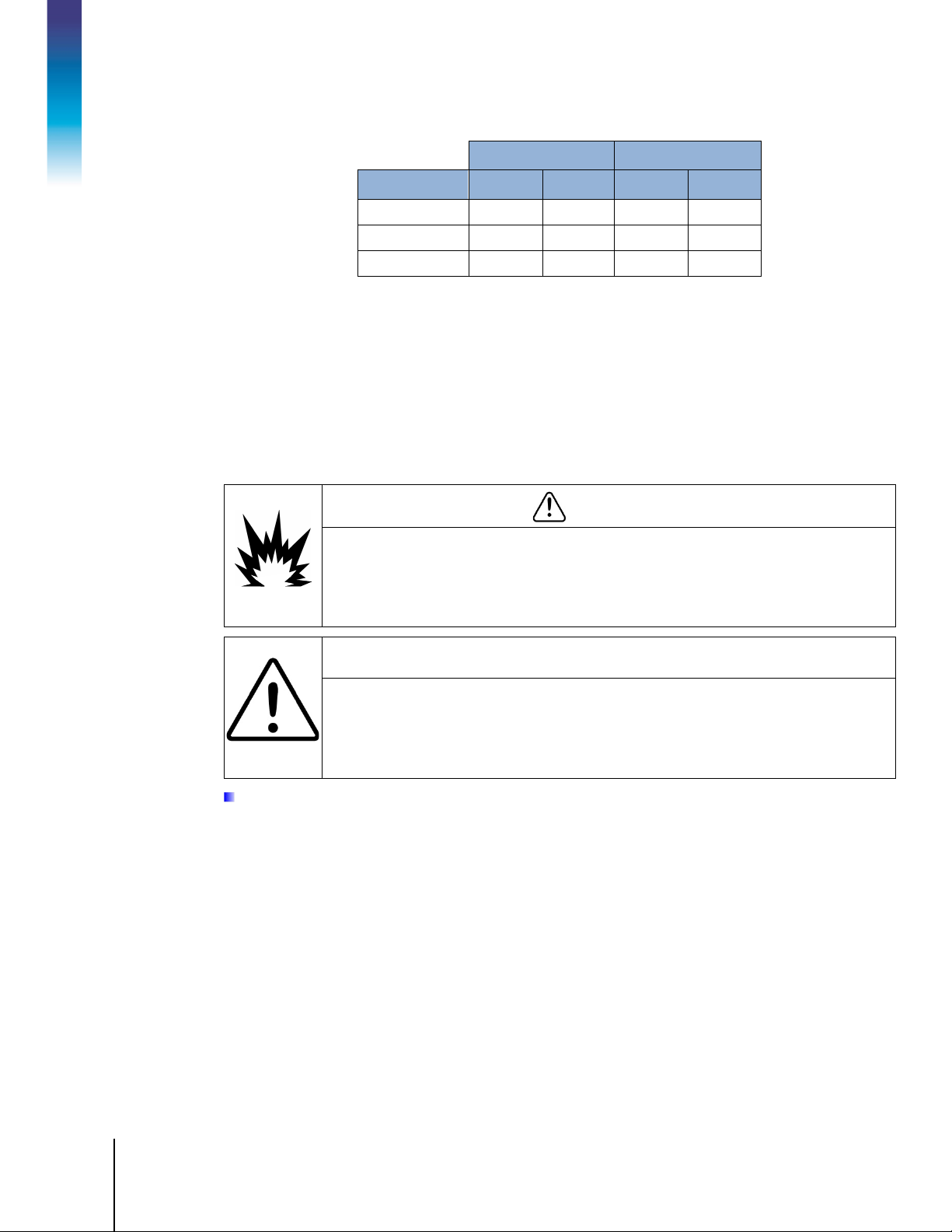
Table 1-3: IND131, IND331 Power Consumption (DC Source)
Input Voltage I (mA) P (W) I (mA) P (W)
18VDC (min) 158 2.84 170 3.06
24 VDC 120 2.88 130 3.12
36 VDC (max) 84 3.02 90 3.24
Values shown are with internal COM2/DIO option and Analog Output option installed and
load cell input loaded with 4 x 350Ω load cells.
Introduction
1.4. Use in Hazardous Areas
Standard versions of the IND131 and IND331 terminals are not certified for use within hazardous
(explosive) areas. Specially marked terminals (models IND131xx and IND331xx) are FM and
KEMA certified for use in hazardous areas classified as Division 2 or Zone 2/22.
DO NOT USE THE STANDARD IND131 OR IND331 TERMINALS IN AREAS CLASSIFIED AS
HAZARDOUS BECAUSE OF COMBUSTIBLE OR EXPLOSIVE ATMOSPHERES. SPECIAL MODELS
(IND131xx AND IND331xx) ARE AVAILABLE FOR THESE APPLICATIONS. CONTACT AN
AUTHORIZED METTLER TOLEDO REPRESENTATIVE FOR INFORMATION ABOUT HAZARDOUS
AREA APPLICATIONS.
IND131 IND331
WARNING
DIV 2 AND ZONE 2/22 INSTALLATION
IF YOU WISH TO INSTALL THE IND131xx OR IND331xx TERMINAL IN A DIVISION 2 OR ZONE
2/22 AREA, REFER TO THE DIVISION 2 AND ZONE 2/22 INSTALLATION INSTRUCTIONS
INCLUDED ON THE RESOURCE CD PROVIDED WITH THE TERMINAL. FAILURE TO COMPLY
WITH THE INSTRUCTIONS PROVIDED THERE COULD RESULT IN BODILY HARM AND/OR
PROPERTY DAMAGE.
Note: When an IND131xx or IND331xx terminal is installed into an area classified as Division 2 or zone
2/22, special AC wiring requirements must be met. Refer to document 64068795 Division 2 and Zone
2/22 Installation Guide.
1.5. Inspection and Contents Checklist
Verify the contents and inspect the package immediately upon delivery. If the shipping container is
damaged, check for internal damage and file a freight claim with the carrier if necessary. If the
container is not damaged, remove the terminal from its protective package, noting how it was
packed, and inspect each component for damage.
If shipping the terminal is required, it is best to use the original shipping container. The terminal
must be packed correctly to ensure its safe transportation.
The package should include:
64067480 | 11 | 05/2018
METTLER TOLEDO IND131/IND131x/IND331/IND331xx Installation Manual
1-7
• IND131, IND131xx, IND331 or IND331xx
• Installation manual
Terminal
• Note: Panel-mount model includes DIN
housing, panel display, mounting brackets
and barrel nuts.
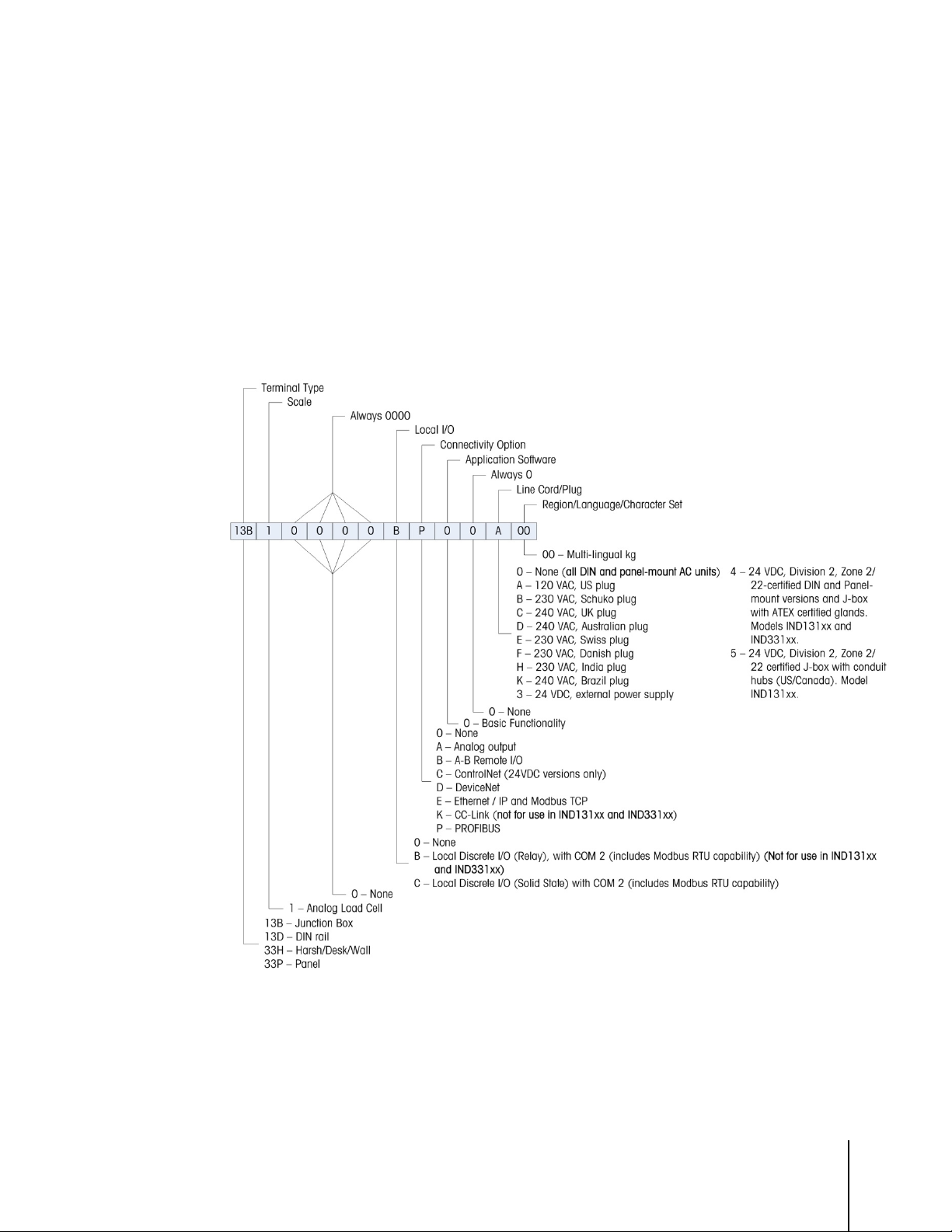
1.6. Model Identification
The IND131/IND331 model number, factory number and serial number are located on the data
plate of the terminal. Refer to Figure 1-1 to verify the configuration of the IND131/IND331 terminal.
• Resource CD (includes all required
documents and manuals)
• Bag of miscellaneous parts, depending on
terminal configuration
Figure 1-1: IND131/IND331 Model Identification Numbers
1-8
METTLER TOLEDO IND131/IND131x/IND331/IND331xx Installation Manual
64067480 | 11 | 05/2018
1.7. Physical Dimensions
The physical dimensions of each of the IND131 and IND331 enclosures are shown in the following
five Figures in mm and [inches].
Introduction
Figure 1-2: IND131 DIN Rail Mount Enclosure Dimensions
Figure 1-3: IND331 Panel Mount Enclosure Dimensions
64067480 | 11 | 05/2018
METTLER TOLEDO IND131/IND131x/IND331/IND331xx Installation Manual
1-9
Figure 1-4: IND331 Harsh Enclosure Dimensions
Figure 1-5: Original IND131 Junction Box Enclosure Dimensions
1-10
METTLER TOLEDO IND131/IND131x/IND331/IND331xx Installation Manual
64067480 | 11 | 05/2018
Introduction
Figure 1-6: Updated IND131 Junction Box Enclosure Dimensions
Figure 1-7 shows the measurements for the drilled holes required to mount the Panel Mount
enclosure.
Figure 1-7: IND331 Panel Mount Drill Template

64067480 | 11 | 05/2018
METTLER TOLEDO IND131/IND131x/IND331/IND331xx Installation Manual
1-11
1.8. Main PCB
4-20mA Analog Output
A-B RIO
CC-Link
ControlNet
DeviceNet
Ethernet/IP
ModbusTCP
PROFIBUS DP
The IND131/IND331 terminal’s main printed circuit board (PCB) provides the analog load cell
scale interface, as well as the COM1 RS-232 serial port.
The main board also contains the power input connection (for either AC or DC supply, depending
on the model), display interfaces (one each for the larger IND331 and smaller IND131 displays), 6
position DIP switch and bus connectors for the PLC and COM2/DIO option boards.
Two LEDs are provided to indicate the operational status of the terminal and a memory card socket
is mounted to the under-side of the PCB to support the optional SD memory.
1.9. Scale Base
The IND131/IND331 terminals support analog scale bases and provide 5 volts of excitation to drive
analog load cells.
A six wire load cell connection is provided with sense lines to help maintain accuracy as the load
cell cable resistance changes with temperature variations.
1.10. Options
The following options are available for the IND131/IND331:
• COM2/DIO (relay output)
One RS-232/485 serial COM port
Internal, discrete I/O (2 inputs and 4 outputs)
─ Inputs are optically isolated solid state and switch selectable as either active or passive
─ Output relays provide one normally open contact per relay
This option not for use with the IND131xx or IND331xx terminal
COM2/DIO (solid state output)
•
One RS-232/485 serial COM port
Internal, discrete I/O (2 inputs and 4 outputs)
─ Inputs are optically isolated solid state and switch selectable as either active or passive
─ Outputs are solid state open collector
•
Programmable Logic Control (PLC) interfaces, including:
1.10.1. COM2 Serial Port
This optional port provides RS-232 and RS-485 communication at rates from 300 to 115.2k baud.
The port is bidirectional and can be configured for various functions such as demand output,
1-12
METTLER TOLEDO IND131/IND131x/IND331/IND331xx Installation Manual
64067480 | 11 | 05/2018
continuous output, SICS host communications, Modbus RTU and ASCII command input (C, T, P,
Z).
1.10.1.1. Modbus RTU
Modbus RTU is a serial communications protocol published by Modicon in 1979 for use with its
programmable logic controllers (PLCs). It is a standard serial communications protocol in industry.
The RTU format follows the commands/data with a cyclic redundancy check checksum as an error
check mechanism to ensure the reliability of data. Modbus RTU is the most common
implementation available for Modbus. Most Modbus devices communicate over a serial EIA-485
physical layer but RS-232 is also supported.
1.10.2. Discrete I/O
Introduction
The discrete I/O interface option is available with dry-contact or solid state relay outputs. The relay
contacts will switch up to 30 volts DC or 250 volts AC at 1A. The solid state outputs will switch up
to 30 volts DC at 350mA maximum.
The inputs are switch selectable as either active (for simple pushbutton control) or passive (for
connection to PLCs or other devices that supply their own power for the inputs).
1.10.3. PLC Interfaces
IND131 and IND331 interface options include 4-20mA Analog Output, A-B RIO, CC-Link,
ControlNet, DeviceNet, Ethernet/IP, Modbus TCP and PROFIBUS DP. Additional details about each of
these interfaces can be found in the IND131/IND331 PLC Interface Manual, provided on the
documentation CD.
1.10.3.1. Analog Output
The Analog Output option provides a 4-20mA analog signal corresponding to the gross or net
weight or the rate The analog signal is isolated and requires that the connected device have a
maximum internal resistance of 500 ohms.
Two solid state error outputs are provided to indicate out of range and error conditions.
1.10.3.2. A-B RIO
The A-B RIO option enables data exchange by bi-directional communications using the Discrete
Data Transfer mode. The IND131/IND331 terminals provide new information for the PLC
approximately 20 times per second. This communication is a high-speed, real-time message
interface between the terminal and the PLC for process control. Division, integer, and floating point
values are supported. The A-B RIO interface does not support Block Transfer mode.
WARNING
THE INTERNAL DISCRETE I/O RELAY OPTION (#72225753 OR #72225757) MUST NOT BE USED
IN A TERMINAL INSTALLED IN AN AREA CLASSIFIED AS DIVISION 2 OR ZONE 2/22. FAILURE TO
COMPLY WITH THIS WARNING COULD RESULT IN BODILY HARM AND/OR PROPERTY DAMAGE.
64067480 | 11 | 05/2018
METTLER TOLEDO IND131/IND131x/IND331/IND331xx Installation Manual
1-13
1.10.3.3. CC-Link
CC-Link is a network that uses dedicated cables to connect distributed modules such as I/O
modules, intelligent function modules, and a special function module, enabling them to be
controlled by the PLC CPU. The CC-Link option board runs as a remote device station. It is designed
to connect to a field network using the CC-Link protocol.
1.10.3.4. ControlNet
ControlNet is an open industrial network designed for cyclic data exchange. The protocol operates
in cycles, known as NUTs, where NUT stands for Network Update Time. Each NUT has two phases,
the first phase is dedicated to scheduled traffic, where all nodes with scheduled data are guaranteed
a transmission opportunity. The second phase is dedicated to unscheduled traffic.
WARNING
THE CC-LINK PLC OPTION (#30059622) MUST NOT BE USED IN A TERMINAL INSTALLED IN AN
AREA CLASSIFIED AS DIVISION 2 OR ZONE 2/22. FAILURE TO COMPLY WITH THIS WARNING
COULD RESULT IN BODILY HARM AND/OR PROPERTY DAMAGE.
WARNING
THE CONTROLNET™ PLC OPTION (64057423) MUST NOT BE USED IN AC VERSIONS OF IND131
AND IND331 TERMINALS. FAILURE TO COMPLY WITH THIS WARNING COULD RESULT IN
EQUIPMENT DAMAGE AND/OR BODILY HARM.
One feature of ControlNet is support for fully redundant network cables.
1.10.3.5. EtherNet/IP and Modbus TCP
The IND131/IND331 terminals support communications of the EtherNet/IP or Modbus TCP interface
options, using a common interface.
EtherNet / IP utilizes commercial, off-the-shelf EtherNet hardware (for example, switches and
routers). It uses the proven Control and Information Protocol (CIP) to provide control, configuration
and data collection capability.
Modbus TCP protocol is a messaging structure that is used to establish master-slave/client-server
communication between intelligent devices. The protocol can be used in multiple master-slave
applications to monitor and program devices; to communicate between intelligent devices and
sensors and instruments; and to monitor field devices using PCs and HMIs.
1.10.3.6. DeviceNet
DeviceNet is an RS-485 based network utilizing CAN chip technology. This network was created for
bit and byte-level devices. The network can be configured to run up to 500Kbits per second
depending on cabling and distances. Messages are limited to 8 unfragmented bytes. The network
can include up to 64 nodes including the master, commonly called the scanner.
1-14
METTLER TOLEDO IND131/IND131x/IND331/IND331xx Installation Manual
64067480 | 11 | 05/2018
1.10.3.7. PROFIBUS DP
The terminal communicates to a PROFIBUS-DP master according to DIN 19 245. PROFIBUS is an
open, RS-485 digital communication system with a wide range of applications, particularly in the
fields of factory and process automation. PROFIBUS is designed for use in fast, time-critical
applications. Additional specifications can be found in PROFIBUS International documents. A
maximum of 126 devices (masters or slaves) can be connected to a bus.
1.10.4. SD Memory Option
An optional SD Memory card provides a medium on which to extract and save the configuration
and calibration settings of the terminal. These can then be restored to the terminal or loaded to a
Introduction
different terminal. This feature can be used to clone the setup of one terminal then transfer it to other
units, which minimizes the chance of error in setting up a new configuration.
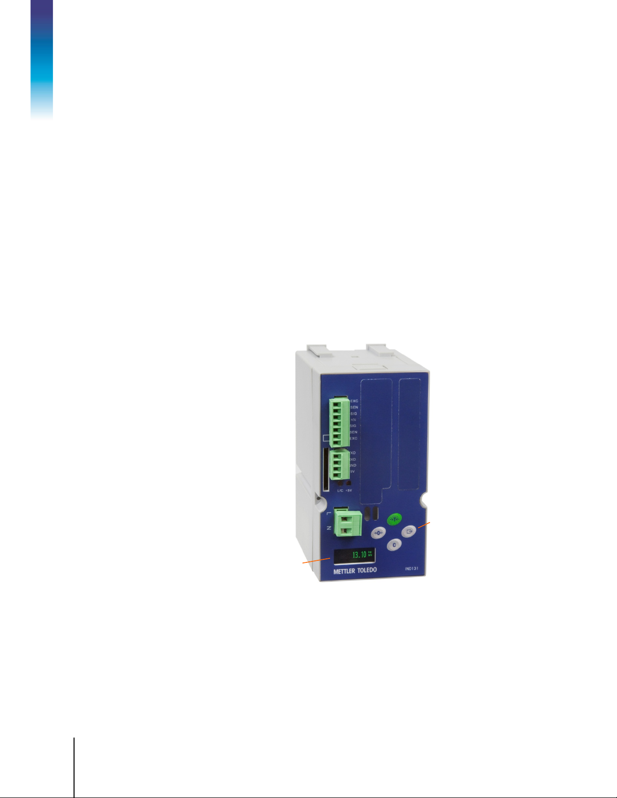
1.11. Display and Keyboard
The IND131 terminal has an Organic LED (OLED) graphic type display. The IND131 DIN model is
shown in Figure 1-8. The same module is used internally in the IND131 Junction Box model.
OLED display
Figure 1-8: IND131 Front Panel Layout
Scale function
and setup menu
navigation
buttons
64067480 | 11 | 05/2018
METTLER TOLEDO IND131/IND131x/IND331/IND331xx Installation Manual
1-15
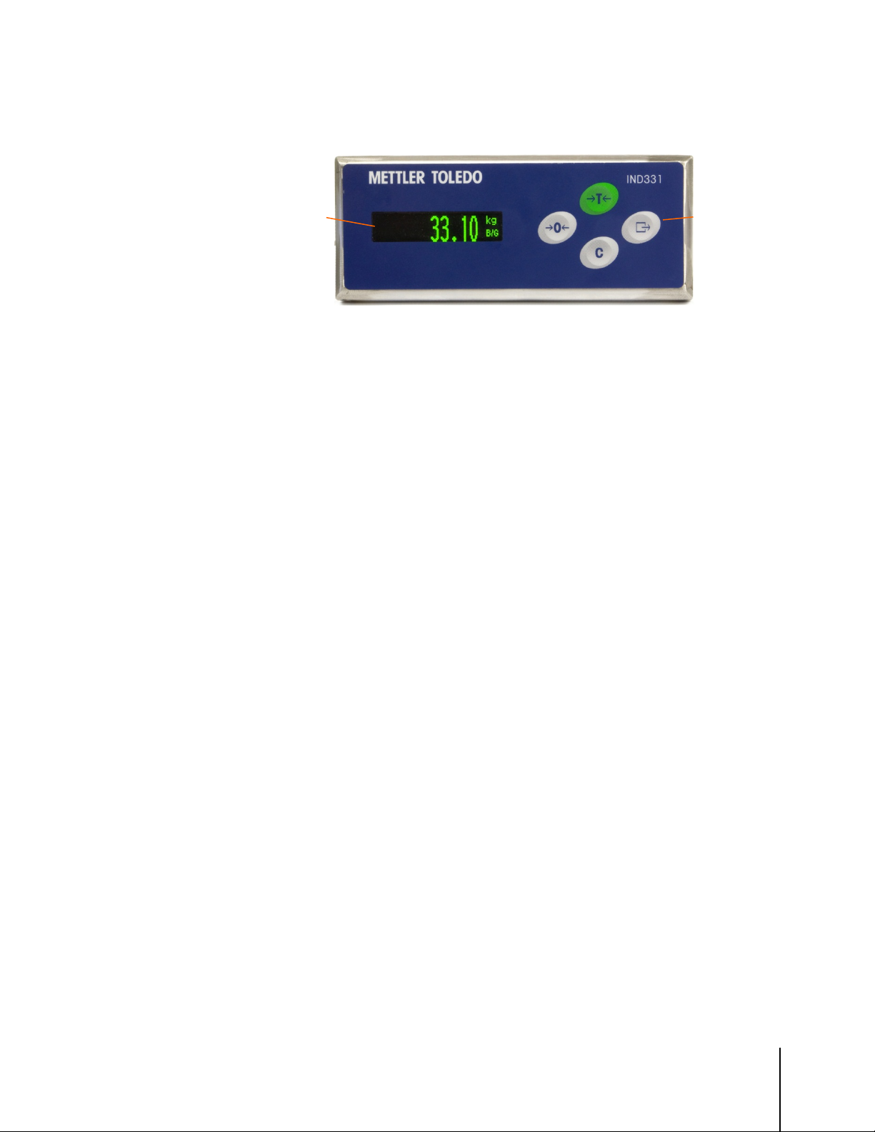
The panel-mount and harsh models of the IND331 (Figure 1-9) include a larger graphic OLED
display.
OLED display
1.11.1. Display Layout
During normal operation, the IND131 and IND331 displays show the Gross or Net weight, together
with the weight units and the weight legend. Graphic symbols are used to indicate center of zero
and motion. For display operation during setup, refer to Chapter 3,
1.11.2. Front Panel Keys
Four dedicated scale function keys are located to the right of the display. These provide the interface
to zero or tare the scale, to clear a tare, and to initiate a print. The same keys are used to enter the
setup menu, to navigate and select setup elements, and to enter values in setup as described in
Chapter 3,
Configuration.
Scale function
and setup menu
navigation
buttons
Figure 1-9: IND331 Front Panel Layout
Configuration.
64067480 | 11 | 05/2018
METTLER TOLEDO IND131/IND131x/IND331/IND331xx Installation Manual
2-1
This chapter covers
2. Installation
This chapter provides installation instructions for the IND131 and IND331
• Opening the Enclosures
• Mounting the Terminals
• Installing Cables and
Connectors
• Main Board Wiring Connections
• PCB Switch Settings
• Capacity Label Instructions
terminals. Please read this chapter thoroughly before beginning installation.
DIV 2 AND ZONE 2/22 INSTALLATION
IF YOU WISH TO INSTALL THE IND131xx OR IND331xx TERMINAL INTO A DIVISION 2 OR
ZONE 2/22 AREA, REFER TO THE DIVISION 2 AND ZONE 2/22 INSTALLATION INSTRUCTIONS
INCLUDED ON THE DOCUMENTATION CD PROVIDED WITH THE TERMINAL. FAILURE TO
COMPLY WITH THE INSTRUCTIONS PROVIDED THERE COULD RESULT IN BODILY HARM
AND/OR PROPERTY DAMAGE.
DO NOT INSTALL, DISCONNECT OR PERFORM ANY SERVICE ON THIS EQUIPMENT BEFORE
THE AREA IN WHICH THE TERMINAL IS LOCATED HAS BEEN SECURED AS NON-HAZARDOUS
BY PERSONNEL AUTHORIZED TO DO SO BY THE RESPONSIBLE PERSON AT THE CUSTOMER’S
SITE.
WARNING
WARNING
IND131xx AND IND331xx TERMINALS USED IN A DIVISION 2 OR ZONE 2/22 ENVIRONMENT
MUST BE INSTALLED AND MAINTAINED PER THE SPECIAL CONDITIONS LISTED IN CHAPTER 2
OF THE DIVISION 2 AND ZONE 2/22 INSTALLATION MANUAL INCLUDED ON THE RESOURCE
CD WITHOUT EXCEPTION. FAILURE TO DO SO COULD RESULT IN BODILY HARM AND/OR
PROPERTY DAMAGE.
WARNING
METTLER TOLEDO ASSUMES NO RESPONSIBILITY FOR CORRECT INSTALLATION OF THIS
EQUIPMENT WITHIN A DIVISION 2 OR ZONE 2/22 AREA. THE INSTALLER MUST BE FAMILIAR
WITH ALL DIVISION 2 OR ZONE 2/22 WIRING AND INSTALLATION REQUIREMENTS.
2-2
METTLER TOLEDO IND131/IND131x/IND331/IND331xx Installation Manual
64067480 | 11 | 05/2018
2.1. Opening the Enclosures
Procedures for opening the various configurations of the IND131 and IND331 terminals differ, and
are shown in the following sections.
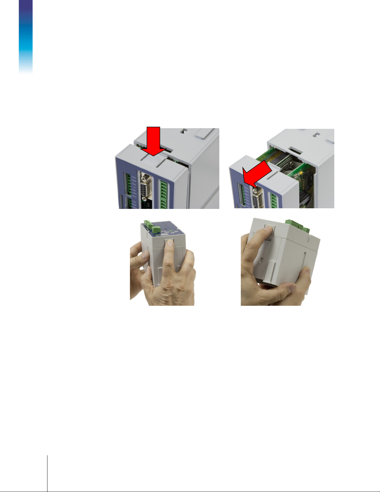
2.1.1. IND131 DIN and IND331 Panel-mount
The front of the DIN enclosure is attached to the rear housing by two snap in place tabs. Both tabs
must be released simultaneously before the front can be slid out of the housing.
Installation
Figure 2-1: Opening the DIN and Panel-mount Enclosures
64067480 | 11 | 05/2018
METTLER TOLEDO IND131/IND131x/IND331/IND331xx Installation Manual
2-3
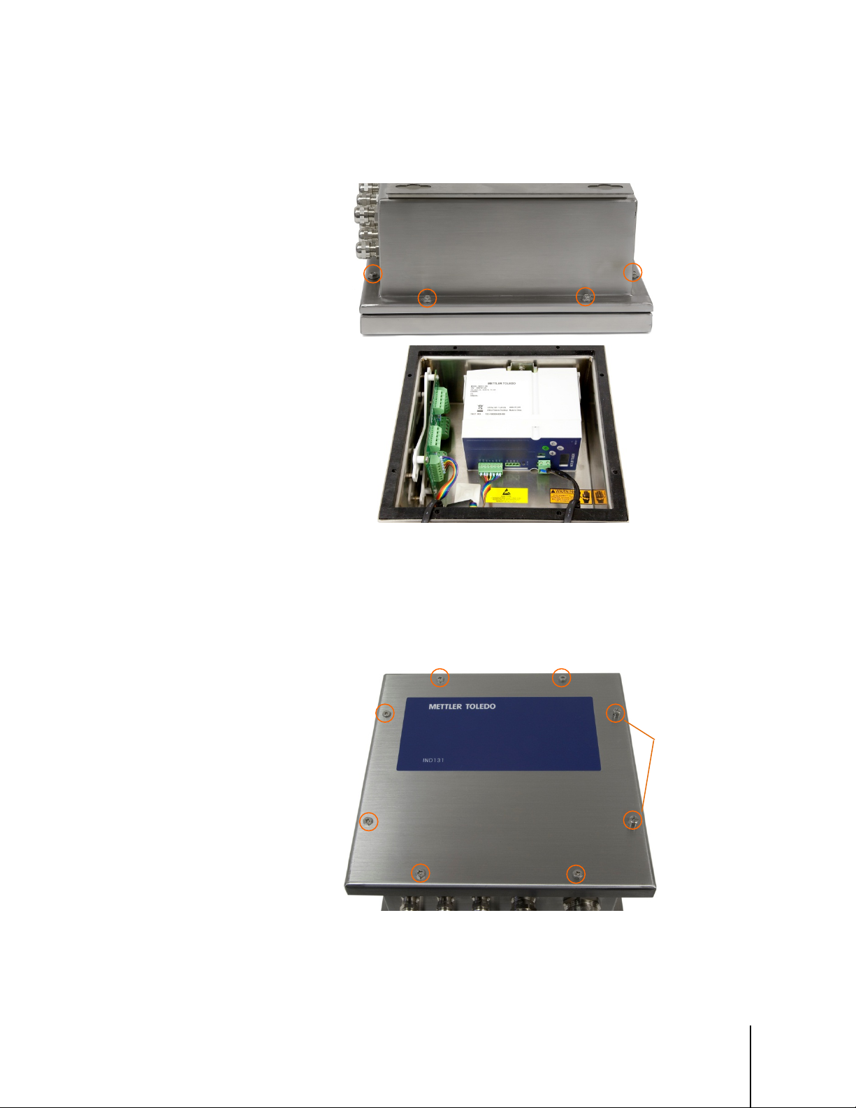
2.1.2. IND131 J-Box
The front cover of the J-Box enclosure is secured with eight (8) screws, four of which are visible in
Figure 2-2. All eight screws must be removed to open the enclosure.
Figure 2-2: J-Box Enclosure
2.1.3. IND131 J-Box, Updated
The front cover of the updated J-Box enclosure is secured with the eight (8) screws indicated in
Figure 2-3. All eight screws must be removed to open the enclosure. Note the location, at right, of
the two screws used to seal the enclosure.
When replacing the cover, the screws should be tightened to 1.5 N-m (12 lbf-in).
Sealing screws
Figure 2-3: J-Box Enclosure, Updated
2-4
METTLER TOLEDO IND131/IND131x/IND331/IND331xx Installation Manual
64067480 | 11 | 05/2018
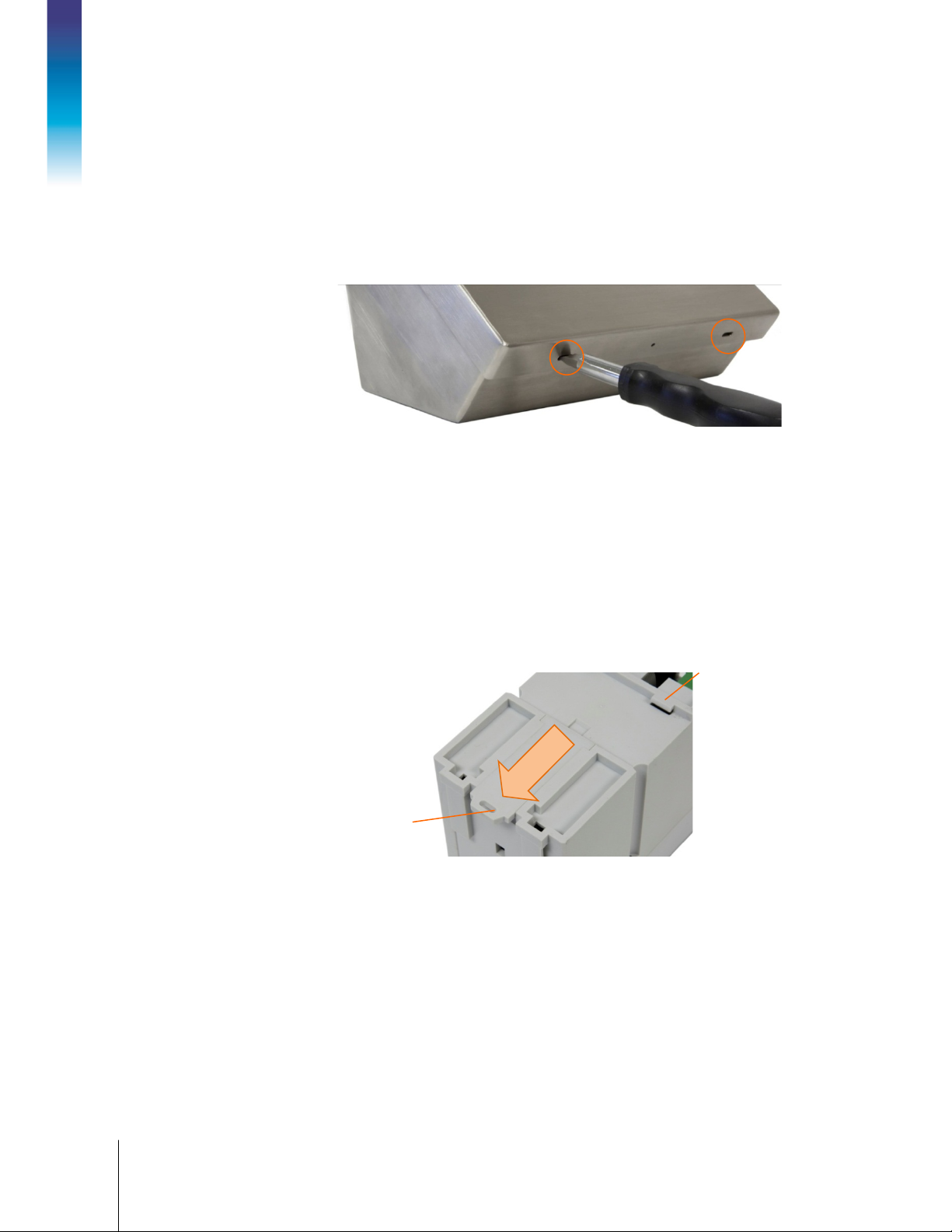
2.1.4. IND331 Harsh
To open the harsh enclosure, use a flat blade screwdriver. Push the blade into each of the two slots
in the cover (indicated in Figure 2-4) to compress the spring clip until the cover pops up. When
both corners are free, press the cover upward until it clears the front edge of the housing. Then,
press it backward until it unlatches the two remaining spring clips. Lift it carefully off the enclosure
and swing it forward. The cover is attached to the enclosure by two strain relief/grounding cables,
and is connected to the main board by the video/keyboard harness (see Figure 2-21).
Installation
Figure 2-4: Opening the IND331 Harsh Enclosure
2.2. Mounting the Terminals
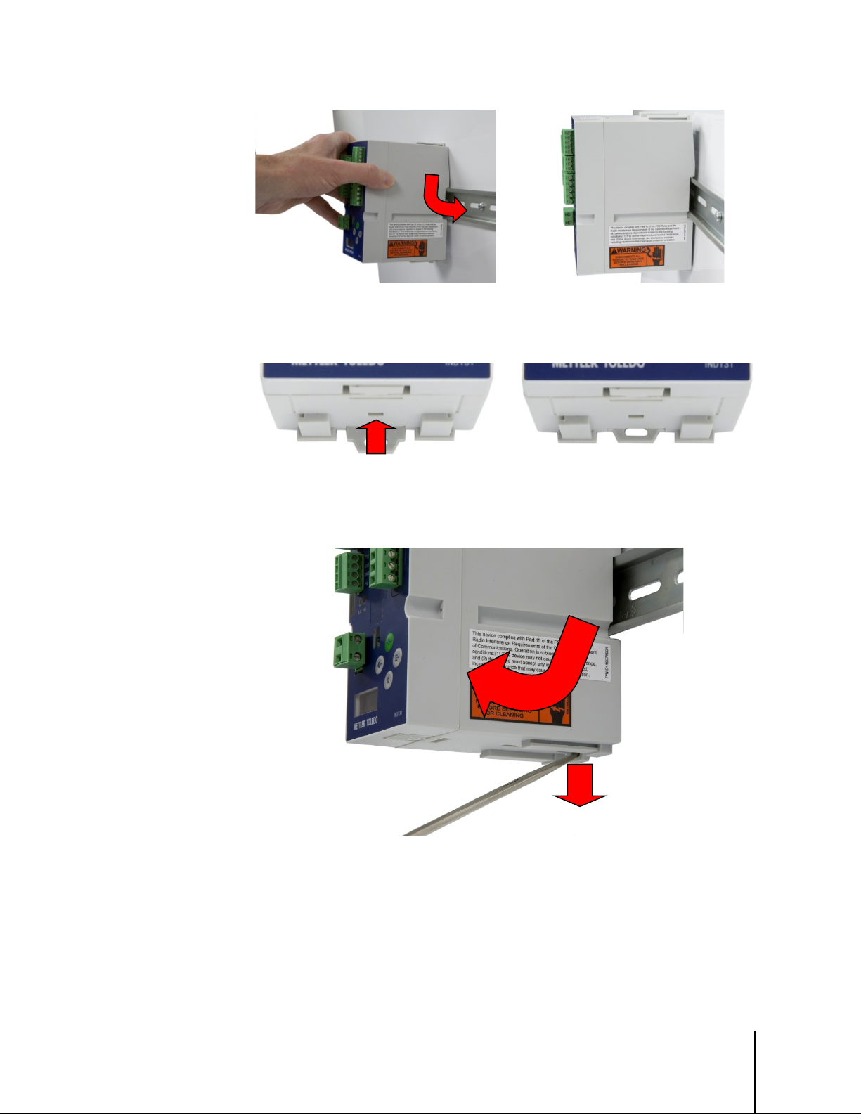
2.2.1. IND131 DIN Module
This model is designed to mount to a 35mm DIN rail. Follow the sequence as shown in Figure 2-5
through Figure 2-7.
First, ensure that the mounting tab is unlocked.
Locking tab
Next, place the back of the IND131 against the DIN rail, with the retaining tabs hooked over one
edge. One tab is indicated in Figure 2-5. With the tabs engaged, press down to seat the module on
the rail (Figure 2-6).
DIN rail
retaining tab
Figure 2-5: DIN Module Locking Tab
64067480 | 11 | 05/2018
METTLER TOLEDO IND131/IND131x/IND331/IND331xx Installation Manual
2-5
Figure 2-6: DIN Module Mounting – Engaging Tabs (left) and Seating on Rail (right)
Finally, press up on the locking tab to secure the module to the DIN rail.
Figure 2-7: DIN Module Mounting 3
To remove the module from the DIN rail, use a screwdriver to pull the tab down to its unlocked
position, pull the bottom of the module outward, then lift the module off.
2
1
Figure 2-8: Removing Module from DIN Rail
2-6
METTLER TOLEDO IND131/IND131x/IND331/IND331xx Installation Manual
64067480 | 11 | 05/2018
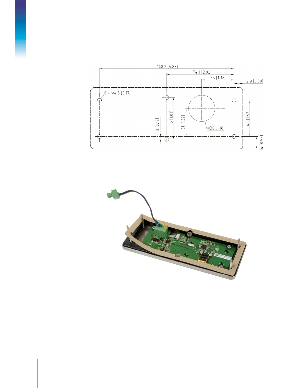
2.2.2. IND331 Panel Mount
To mount the IND331 to a panel, six screw holes and one larger hole for the display cable must be
made (Figure 2-9).
Installation
Figure 2-9: Panel Mounting Template
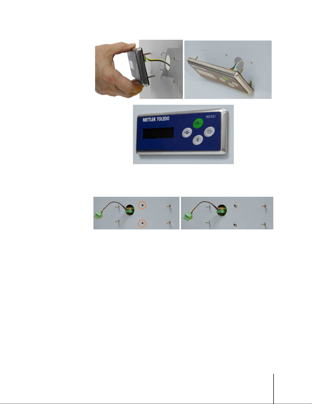
Next, mount the IND331 operator interface to the panel. First, peel off the backing paper (shown
partly removed in Figure 2-10) from the adhesive surface of the gasket. Feed the keyboard/video
harness through the larger hole in the panel (Figure 2-11).
Figure 2-10: IND331 Operator Interface
64067480 | 11 | 05/2018
METTLER TOLEDO IND131/IND131x/IND331/IND331xx Installation Manual
2-7
Figure 2-11: Mounting the Operator Interface
From the back of the panel, install two screws to retain the operator interface. Tighten the screws to
1.5 N-m (12 lbf-in).
Figure 2-12: Fastening Operator Interface in Position
2.2.3. Direct Mounting
The standard communication harness between the panel-mount display operator interface
assembly and the rear housing is approximately 9 cm (3.5 in.) in length and is designed to permit
the rear housing to mount directly to the back of the operator interface panel. This installation is
described in the Direct Mounting section below, and illustrated in Figure 2-13 and Figure 2-14.
For applications where there is insufficient clearance for the rear housing to be mounted directly
behind the front panel, or to mount the rear housing to a DIN rail separate from the display, remote
mounting of the rear housing is supported. The short cable between the operator interface and the
rear housing can be replaced with a cable that extends the distance as far as 15m (50 ft). Remote
mounting of the rear housing is described in the Remote Mounting section below and shown in
Figure 2-18, Figure 2-19 and Figure 2-20.
 Loading...